WO2014167629A1 - 操舵制御装置および操舵制御方法 - Google Patents
操舵制御装置および操舵制御方法 Download PDFInfo
- Publication number
- WO2014167629A1 WO2014167629A1 PCT/JP2013/060634 JP2013060634W WO2014167629A1 WO 2014167629 A1 WO2014167629 A1 WO 2014167629A1 JP 2013060634 W JP2013060634 W JP 2013060634W WO 2014167629 A1 WO2014167629 A1 WO 2014167629A1
- Authority
- WO
- WIPO (PCT)
- Prior art keywords
- steering
- assist torque
- vehicle
- speed
- steering assist
- Prior art date
Links
Images


Classifications
-
- B—PERFORMING OPERATIONS; TRANSPORTING
- B62—LAND VEHICLES FOR TRAVELLING OTHERWISE THAN ON RAILS
- B62D—MOTOR VEHICLES; TRAILERS
- B62D5/00—Power-assisted or power-driven steering
- B62D5/04—Power-assisted or power-driven steering electrical, e.g. using an electric servo-motor connected to, or forming part of, the steering gear
- B62D5/0457—Power-assisted or power-driven steering electrical, e.g. using an electric servo-motor connected to, or forming part of, the steering gear characterised by control features of the drive means as such
- B62D5/046—Controlling the motor
- B62D5/0463—Controlling the motor calculating assisting torque from the motor based on driver input
-
- B—PERFORMING OPERATIONS; TRANSPORTING
- B62—LAND VEHICLES FOR TRAVELLING OTHERWISE THAN ON RAILS
- B62D—MOTOR VEHICLES; TRAILERS
- B62D5/00—Power-assisted or power-driven steering
- B62D5/04—Power-assisted or power-driven steering electrical, e.g. using an electric servo-motor connected to, or forming part of, the steering gear
- B62D5/0457—Power-assisted or power-driven steering electrical, e.g. using an electric servo-motor connected to, or forming part of, the steering gear characterised by control features of the drive means as such
- B62D5/046—Controlling the motor
- B62D5/0466—Controlling the motor for returning the steering wheel to neutral position
Definitions
- the present invention relates to a steering control device that assists the steering of the driver.
- the handle return torque is generated by the motor in order to improve the handle return characteristic when the handle is released at a low vehicle speed.
- a function of a target return speed with respect to a predetermined steering angle is selected according to the average feed speed and the vehicle speed, and the assist force is generated so that the return speed of the steering wheel becomes the calculated target return speed.
- the drive control of the means is performed.
- the average feed speed is calculated from the deviation between the steering angle at the start of feed steering and the steering angle at the end of feed steering and the elapsed time.
- the target return speed is changed by feed steering.
- the steering of the steering wheel is determined from the steering torque and the steering speed, and the output of the steering wheel return control is set to zero when the steering is determined. This prevents an increase in steering torque when the steering wheel is held.
- the magnitude of the state quantity indicating the turning state of the vehicle when the handle is released or when the handle is turned back for example, the magnitude of the steering angle when the handle is released. Accordingly, the target return speed and return torque could not be adjusted appropriately. Therefore, when the feed speed is the same, there is a problem that it takes time for the steering wheel to return to the neutral position if the steering angle when the hand is released is large.
- the target return speed is set so that the target return speed is larger than the steering angle as in the above-mentioned Patent Document 1
- the steering wheel is neutral. Since the road surface reaction torque acting in the direction of returning to the position increases, both the road surface reaction torque and the return torque act, and the actual steering speed may increase rapidly.
- an increase in steering torque can be suppressed at the time of steering determination, the return torque increases when return steering is started, which may give the driver a sense of discomfort.
- the present invention has been made to solve the above-described problems, and can provide a suitable steering assist torque regardless of the position of the steering wheel when the steering wheel is turned back or when the steering wheel is released.
- the object is to provide a control device and the like.
- the present invention relates to an actuator that applies a steering assist torque to a steering system of a vehicle, a vehicle turning state detection unit that detects a state quantity indicating the turning state of the vehicle, and a steering holding determination unit that determines a steering holding state of the steering system. And a storage unit that stores the state quantity detected by the vehicle turning state detection unit as a state determination amount at the time of the steering determination when the steering determination unit determines that the state is the steering holding state,
- a steering control device or the like comprising: a steering assist torque calculating unit that calculates the steering assist torque based on an absolute value; and an actuator control unit that controls the actuator according to the calculated steering assist torque.
- the present invention it becomes possible to change the steering assist torque according to the magnitude of the state quantity at the time of steering determination, and it is possible to perform suitable steering regardless of the position of the steering wheel when the steering wheel is turned back or when the steering wheel is released. Auxiliary torque can be obtained, and thus a suitable steering wheel return and a suitable steering feeling can be realized.
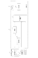
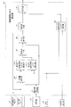
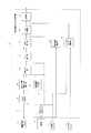
- FIG. 1 is a diagram showing an example of the configuration of a steering control device according to the present invention.
- the left and right steered wheels 3 are steered according to the rotation of the steering shaft 2 connected to the handle 1.
- the steering wheel 1 is provided with a steering angle sensor 4 for detecting a steering angle.
- a torque sensor 5 is disposed on the steering shaft 2 and detects a steering torque acting on the steering shaft 2.
- the motor 6 is connected to the steering shaft 2 via the speed reduction mechanism 7, and the steering assist torque generated by the motor 6 can be applied to the steering shaft 2.
- the vehicle speed is detected by a vehicle speed sensor 8.
- the current flowing through the motor 6 is detected by a current sensor 9.
- the voltage between the terminals of the motor 6 is detected by the voltage sensor 10.
- the control unit 11 calculates, for example, a steering assist torque generated by the motor 6 and controls a current of the motor 6 necessary for generating the steering assist torque.
- the control unit 11 is provided with a memory including a ROM and a RAM described later.
- a microcomputer (CPU), a current driver for driving a motor current (flowing a desired current), and the like are provided.
- the control unit 11 includes a steering determination unit 22 configured by a microcomputer, a steering assist torque calculator 24, a storage unit 23, a current driver 12, and a memory (device) M.
- a vehicle turning state detector 21 including a steering angle sensor 4, a vehicle speed sensor 8, and a torque sensor 5 are connected to the control unit 11.
- the storage device 23 writes and reads necessary data to and from the memory M that is a storage medium.
- step S ⁇ b> 1 the steering angle is detected using the steering angle sensor 4 as the vehicle turning state detector 21. That is, in this embodiment, the steering angle is used as a state quantity indicating the turning state of the vehicle.
- step S2 the steering determination unit 22 determines whether or not the steering state of the vehicle steering system, that is, whether or not the steering wheel 1 remains at a substantially constant steering angle.
- the steering angle detected by the vehicle turning state detector 21 is used, the steering speed is calculated from the steering angle, and a situation where the magnitude of the steering speed is smaller than a predetermined steering speed threshold is determined as the holding state. .
- step S3 in the storage device 23, the detected value of the vehicle turning state detector 21 when the steering determination unit 22 determines that the steering state is maintained is stored in the memory M as the state determination amount at the time of steering determination. That is, in this embodiment, the steering angle detected by the steering angle sensor 4 when the steering determination unit 22 determines that the steering is held is stored in the memory M as the steering determination steering angle (first stored value). .
- a predetermined storage value is stored in the memory M in advance as the initial value of the steering angle at the time of the steering determination in the period until the steering determination unit 22 determines the steering state for the first time.
- the predetermined stored value is set to zero.
- the storage device 23 updates and stores the stored state value at the time of the steering determination, which is stored when the steering determination unit 22 newly determines that the steering state is maintained.
- the steerage determination unit 22 sets the state amount at the time of steerage determination to a predetermined second stored value when certain conditions are met even when the steerage determination unit 22 has not newly determined the steered state. Update and remember. For example, even when the predetermined second stored value is set to zero and the steering speed is larger than the steering speed threshold, if the steering angle is equal to or less than a predetermined zero determination threshold that can determine that the steering angle is nearly zero, the steering The state quantity at the time of determination is set to zero, updated to the second stored value, and stored.
- step 4 the steering assist torque calculator 24 calculates the magnitude of the state quantity at the time of holding determination, that is, the absolute value of the steering angle at the time of holding determination, and based on the absolute value of the steering angle at the time of holding determination, Calculate steering assist torque.
- FIG. 4 A block diagram of the steering assist torque calculator 24 is shown in FIG. 4, and an operation flowchart is shown in FIG. The operation shown in the operation flowchart is repeatedly executed at a control period of a predetermined time.
- a steering angle is used as an input signal used by the steering assist torque calculator 24.
- the steering assist torque calculator 24 includes an absolute value calculator 31, a state quantity corrector 32, a first target steering speed setter 33, a second target steering speed setter 34, a weighter 35, and a gain correction.
- step S ⁇ b> 21 the absolute value calculator 31 calculates the magnitude of the state quantity at the time of steering determination. That is, the absolute value of the state quantity at the time of steering determination is calculated. In this embodiment, the absolute value of the steering-holding determination steering angle stored in the memory by the storage unit 23 is calculated. In step S22, the state quantity corrector 32 corrects the steering angle based on the absolute value of the state quantity at the time of holding determination, and calculates the corrected steering angle. As a specific correction method, processing shown in the following formula (1) is performed.
- ⁇ h steering angle
- ⁇ n a preset reference steering angle
- absolute value of the steering angle at the time of holding judgment
- ⁇ h1 Steering angle after correction.
- ⁇ n may be stored in advance in a memory and used.
- Formula (1) represents that the steering angle corresponding to the case where the absolute value
- step S23 the first target steering speed setting unit 33 sets the first target steering speed corresponding to the corrected steering angle.
- first target steering speed information for a steering angle from zero to a reference steering angle is stored in advance in the memory M as map information.
- a first target steering speed d ⁇ ref1 corresponding to the corrected steering angle ⁇ h1 is calculated.
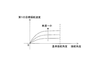
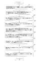
- FIG. 6 An example of the map information of the first target steering speed information is shown in FIG.
- the target steering speed is stored in the memory according to the vehicle speed Vel, and the first target steering speed is set according to the corrected steering angle and the vehicle speed.
- the three curves in FIG. 6 indicate the first target steering speed for each of three types of vehicle speeds (the vehicle speed decreases from bottom to top) with respect to the steering angle from zero to the reference steering angle.
- the first target steering speed has a characteristic that the target steering speed increases as the steering angle increases. As the vehicle speed increases, the first target steering speed decreases.
- the first target steering speed may be set as a function as shown in the following equation (2).
- step S24 the second target steering speed setting unit 34 sets the second target steering speed d ⁇ ref2 corresponding to the corrected steering angle.
- the second target steering speed information for the steering angle from zero to the reference steering angle is stored in advance in the memory M as map information.
- a second target steering speed d ⁇ ref2 corresponding to the corrected steering angle ⁇ h1 is calculated.
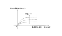
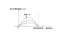
- FIG. 7 An example of the map information of the second target steering speed information is shown in FIG.
- the target steering speed is stored in the memory according to the vehicle speed Vel
- the second target steering speed is set according to the corrected steering angle and the vehicle speed. .
- the three curves in FIG. 7 indicate the second target steering speed for each of three types of vehicle speeds (the vehicle speed decreases from bottom to top) with respect to the steering angle from zero to the reference steering angle.
- the second target steering speed is a characteristic that initially increases as the steering angle increases at the same vehicle speed, but then decreases after reaching the maximum target steering speed.
- the second target steering speed may be set as a function as in the following equation (3).
- step S22 the steering angle input to the map is corrected.
- the horizontal axis steering angle set in advance in the map information is used. That is, the steering angle from zero to the reference steering angle may be corrected. This corrects the input signal to be calculated according to the magnitude of the state quantity at the time of steering determination, and calculates the steering assist torque based on the corrected input signal.
- the weighting unit 35 calculates the third target steering speed by weighting the first target steering speed and the second target steering speed based on the absolute value
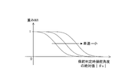
- An example of the weight W1 used in the weighter 35 is shown in FIG.
- Data relating to such a weight W1 is stored in advance in the memory M, for example.
- the data in FIG. 8 is stored in advance in the memory M, for example.
- the weight W1 is set to 1, and the weight W1 is set to approach 0 as the absolute value of the steering angle during steering determination increases.
- W1 is changed according to the vehicle speed.
- the three curves in FIG. 8 indicate the respective weights at three types of vehicle speeds (the vehicle speed decreases from left to right). When compared with the same steering angle during steering determination, the weight W1 increases as the vehicle speed decreases.
- the third target steering speed d ⁇ ref3 is calculated by Expression 4.
- D ⁇ ref3 W1 ⁇ d ⁇ ref1 + (1-W1) ⁇ d ⁇ ref2 (4)
- the third target steering speed d ⁇ ref3 is mainly set at the first target steering speed d ⁇ ref1, and the absolute value of steering angle at steering determination
- is large, the third target steering speed d ⁇ ref3 is set mainly at the second target steering speed d ⁇ ref2. For example, if W1 0.5, the third target steering speed d ⁇ ref3 is a target return speed obtained by averaging the first target steering speed d ⁇ ref1 and the second target steering speed d ⁇ ref2.
- the weight W1 is a weight that continuously changes from 0 to 1, but using a switch (not shown) or by comparing the steering angle at the time of holding determination with a predetermined threshold, One of the first target steering speed d ⁇ ref1 and the second target steering speed d ⁇ ref2 may be selected and the third target steering speed d ⁇ ref3 may be set according to the steering angle at the time of steering determination.
- step S26 the gain corrector 36 sets a correction gain based on the absolute value
- the target steering speed d ⁇ ref4 is calculated.
- An example of the correction gain W2 used in the gain corrector 36 is shown in FIG. Such data relating to the correction gain W2 is stored in advance in the memory M, for example.
- the correction gain W2 is set to increase as the absolute value of the steering angle during steering determination
- the fourth target steering speed d ⁇ ref4 is calculated by the following equation (5).
- step S27 the sign corrector 37 sets the sign of the fourth target steering speed d ⁇ ref4 from the sign of the steering angle, and sets it as the fifth target steering speed d ⁇ ref5.
- the target steering speed is preferably set to the neutral position when the handle 1 is released and when the steering wheel 1 is turned back (when the steering wheel is returned to a neutral position from a certain steering angle). Therefore, the sign of the target steering speed is set to be opposite to the sign of the steering angle.
- step S28 the steering speed calculator 38 calculates the steering speed d ⁇ act from the steering angle ⁇ h. That is, the steering speed is calculated by differentiating the steering angle detected by the steering angle sensor 4. The steering speed may be calculated by differentiating the rotation angle of the motor 6 and then considering the reduction ratio of the speed reduction mechanism 7. Further, the steering speed may be estimated from the induced voltage of the motor 6 (obtained from the voltage sensor 10) or the like.
- step S29 the steering assist torque 1 is calculated in the speed controller 39 so that the steering speed follows the fifth target steering speed d ⁇ ref5.
- the steering assist torque 1 (Ta1) is calculated by multiplying the deviation between the target steering speed d ⁇ ref5 and the steering speed d ⁇ act by the feedback gain Kp.
- Ta1 Kp ⁇ (d ⁇ ref5-d ⁇ act) (6)
- the steering assist torque 1 (Ta1) is limited in magnitude after the calculation result of the above formula (6).
- the size is greater than or equal to the threshold Ta1_max.
- Ta1_max is set to a magnitude that allows the driver to steer the steering wheel 1 by resisting the steering assist torque 1 (Ta1).
- step S30 the steering assist torque 2 calculator 40 calculates the steering assist torque 2 based on at least the steering torque.
- the relationship between the vehicle speed Vel and the steering assist torque 2 with respect to the steering torque is stored in the memory M in advance, and the steering torque from the torque sensor 5 and the vehicle speed Vel from the vehicle speed sensor 8 are stored. Accordingly, steering assist torque 2 (Ta2) is set.
- step S31 the adder 41 adds the steering assist torque 1 (Ta1) and the steering assist torque 2 (Ta2), and finally calculates the steering assist torque generated by the motor 6.
- step S4 after the steering assist torque finally generated by the motor 6 is calculated by the steering assist torque calculator 24 as described above in step S4, the steering calculated by the motor 6 in the current driver 12 in step S5.
- the current of the motor 6 is driven so as to generate the auxiliary torque. That is, current control of the motor 6 is performed. Actually, the current control of the motor 6 is performed so that the steering assist torque calculated through the speed reduction mechanism 7 is transmitted to the steering system.
- the steering angle ⁇ h is corrected based on, for example, the absolute value
- the first target steering speed ⁇ dref1 The second target steering speed ⁇ dref2 is set by a predetermined second steering angle-target steering speed conversion when the angle is large.
- first and second target steering speeds ⁇ dref1 and ⁇ dref2 are weighted W1, and the first target steering speed ⁇ dref1 is large in the region where the absolute value of the steering angle at the time of the holding determination is small, and the second target steering speed is large in the region.
- the third target steering speed ⁇ dref3 is set by weighting and adding ⁇ dref2 to be main.
- the third target steering speed ⁇ dref3 is further corrected by a correction gain W2 that increases as the absolute value of the steering angle at the time of steering determination increases, so that the fourth target steering speed ⁇ dref4 is set and further converted to an opposite sign.
- a fifth target steering speed ⁇ dref5 is set.
- the difference between the fifth target steering speed ⁇ dref5 and the steering speed d ⁇ act calculated from the steering angle ⁇ h is multiplied by the feedback gain Kp, and the steering assist torque 1 (Ta1) is set so as to follow the fifth target steering speed ⁇ dref5. Ask. Then, the steering assist torque generated by the motor 6 is calculated by adding the steering assist torque 1 (Ta1) and the steering assist torque 2 (Ta2) obtained from the assist map (FIG. 10) based on the vehicle speed and the steering torque.
- the weighting unit 35 is configured to weight the first target steering speed d ⁇ ref1 and the second target steering speed d ⁇ ref2 based on the absolute value of the steering angle at the time of holding determination, the third target steering speed d ⁇ ref3 is calculated. It is possible to set an appropriate target steering speed according to the turning state during the return steering.
- the first target steering speed d ⁇ ref1 selected in the region where the steering angle at the time of the steering holding determination is small is the target steering speed that is not zero after the release, so that the road surface reaction force torque is small and the handle 1 returns to the neutral position.
- the handle 1 can be returned to the neutral position even in a region where there is not.
- the switchback steering is performed from the region where the steering angle at the time of holding determination is small, the gradient of the assist map shown in FIG. 10 is small and the steering assist torque 2 (Ta2) is small, so the first target steering is performed.
- the steering assist torque 1 (Ta1) set by the speed d ⁇ ref1 is easily transmitted to the driver. Since the first target steering speed d ⁇ ref1 has a characteristic that the target steering speed increases as the steering angle increases, the steering torque of the driver smoothly decreases as the steering angle decreases, and a suitable steering feeling is obtained. Can be realized.
- the target steering speed can be set to zero or near zero.
- the steering assist torque 1 (Ta1) for suppressing the steering speed, and it is possible to suppress a rapid increase in the return speed when the hand is released.
- the target steering speed is near zero and the steering speed is also near zero. Therefore, the steering assist torque 1 (Ta1) becomes small and the driver's steering torque is not changed. Therefore, a suitable steering feeling can be realized.
- the target steering speed gradually increases from near zero, so that a sudden increase in the return torque can be prevented, a smooth change in the steering torque can be realized, and a suitable steering feeling can be obtained. Can do.
- an appropriate target steering speed 1 can be set even when switching back from the intermediate steering angle. That is, it is possible to set an appropriate target steering speed in all the steering regions, and thus to set an appropriate steering assist torque.
- the correction gain W2 is set based on the absolute value of the steering angle at the time of holding determination, the third target steering speed d ⁇ ref3 is corrected based on the correction gain, and the fourth target steering speed d ⁇ ref4. Therefore, it is possible to adjust the magnitude of the target steering speed in accordance with the steering angle when the hand is released.
- the time to return to the neutral position can be adjusted according to the steering angle at the time of releasing, for example, from releasing from a large steering angle to releasing to a neutral position by releasing from a small steering angle.
- a suitable return of the handle 1 can be realized by making the times substantially equal. That is, according to the configuration of this embodiment, it is possible to obtain a suitable steering assist torque with respect to the handle position when the handle is turned back or when the handle is released. Feeling can be realized.
- this method it is necessary to have target steering speed information or set a function corresponding to each of the steering angle magnitudes at the time of holding determination, and the amount of memory increases.
- the speed controller 39 can guarantee a state where the driver can always steer by limiting the steering assist torque 1 (Ta1) to a magnitude that allows the driver to resist and steer the steering wheel 1. it can.
- the steering determination unit 22 is a predetermined zero that can be determined as a situation in which the steering angle is substantially near zero even in a situation where the steering speed is greater than the steering speed threshold (a situation in which the steering angle is almost zero). If the steering angle is equal to or less than the threshold for determination), the steering angle at the time of holding determination is updated to the stored value 2 with the steering angle being set to zero, so that the steering wheel 1 is returned to the neutral position by switchback steering. When the additional steering is performed, the steering angle can be set to zero and the target steering speed can be set to zero. As a result, it is possible to prevent the target steering speed from being set to be greater than zero during additional steering, and to suppress an increase in the driver's steering torque.
- the steering angle detected by the steering state detector (vehicle turning state detector) 21 is used as the signal used by the steering determination unit 22, but the present invention is not limited to this.
- the rotation angle and rotation speed of the motor 6 can be used.
- the vehicle turning state detector 21 includes a sensor 4a that detects each of the factors, and a calculation unit 4b that calculates a desired factor such as a steering angle from the detection signal from the sensor. And the desired number (hereinafter the same).
- the same input signal used by the steering assist torque calculator 24 and the state quantity detected by the vehicle turning state detector 21 are used.
- the state quantity corrector 32 can easily carry out the state quantity enlargement / reduction correction and reduce the calculation load.
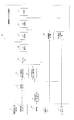
- FIG. FIG. 11 is a block diagram of the steering assist torque calculator in Embodiment 2 of the present invention
- FIG. 12 is an operation flowchart of the steering assist torque calculator.
- Other parts are basically the same as those of the above embodiment.
- the steering angle is used as an input signal used in the steering assist torque calculator.
- a first steering assistance torque 1 setting device 33_2 instead of the first target steering speed setting device 33 and the second target steering speed setting device 34, a first steering assistance torque 1 setting device 33_2, A second steering assist torque 1 setter 34_2 is provided. Further, the steering speed calculator 38 and the speed controller 39 are not included.
- step S23_2 the first steering assist torque 1 (Ta1-1) corresponding to the corrected steering angle ⁇ h1 is set by the first steering assist torque 1 setting device 33_2.
- the first steering assist torque 1 setter 33_2 information of the first steering assist torque 1 with respect to the steering angle from zero to the reference steering angle is stored in advance in the memory M as map information.
- An example of the map information of the first steering assist torque 1 is shown in FIG. Then, the first steering assist torque 1 corresponding to the corrected steering angle ⁇ h1 is calculated.
- the map information of the first steering assist torque 1 is stored in the memory M according to the vehicle speed, and the first steering assist torque 1 (Ta1-1) is determined according to the corrected steering angle and the vehicle speed.
- the steering assist torque 1 is set.
- the three curves in FIG. 13 indicate the first steering assist torque 1 with respect to the steering angle from zero to the reference steering angle at three types of vehicle speeds (the vehicle speed decreases from bottom to top).
- the first steering assist torque 1 has a characteristic that the steering assist torque 1 increases as the steering angle increases. As the vehicle speed increases, the first steering assist torque 1 has a characteristic of decreasing. Similar to the above-described embodiment, the first steering assist torque 1 may be set as a function instead of the map information.
- step S24_2 the second steering assist torque 1 setting unit 34_2 sets the second steering assist torque 1 (Ta1-2) corresponding to the corrected steering angle.
- information of the second steering assist torque 1 with respect to the steering angle from zero to the reference steering angle is stored in advance in the memory M as map information.
- An example of the map information of the second steering assist torque 1 is shown in FIG. Then, the second steering assist torque 1 corresponding to the corrected steering angle ⁇ h1 is calculated.
- the map information of the second steering assist torque 1 is stored in the memory M in accordance with the vehicle speed, and the second steering assist torque 1 (Ta1-2) in accordance with the corrected steering angle and vehicle speed.
- the steering assist torque 1 is set.
- the three curves in FIG. 14 indicate the second steering assist torque 1 with respect to the steering angle from zero to the reference steering angle at three types of vehicle speeds (the vehicle speed decreases from bottom to top).
- the second steering assist torque 1 has a characteristic of decreasing as the vehicle speed increases.
- the second steering assist torque 1 has a characteristic that increases at the beginning as the steering angle increases at the same vehicle speed, but then decreases after reaching the maximum steering assist torque. Similar to the above embodiment, the second steering assist torque 1 may be set as a function instead of the map information.
- step S22 the steering angle input to the map is corrected.
- the horizontal axis steering angle set in advance in the map information instead of the steering angle. That is, the steering angle from zero to the reference steering angle may be corrected.
- step S25_2 the weighter 35 learns the first steering assist torque 1 (Ta1-1) and the second based on the absolute value
- the steering assist torque 1 (Ta1-2) is weighted to calculate the third steering assist torque 1 (Ta1-3).
- step S26_2 the gain corrector 36 sets a correction gain on the basis of the absolute value
- the steering assist torque 1 (Ta1-3) is corrected, and the fourth steering assist torque 1 (Ta1-4) is calculated.
- step S27_2 the sign corrector 37 sets the sign of the fourth steering assist torque 1 (Ta1-4) from the sign of the steering angle ⁇ h in accordance with step S27 of the above embodiment, and the fifth steering The auxiliary torque is 1 (Ta1-5).
- the fifth steering assist torque 1 (Ta1-5) becomes the steering assist torque 1Ta1.
- the target steering speed is intended to suitably return the handle to the neutral position when the handle 1 is released and turned back.
- the auxiliary torque 1 is set so that the sign of the auxiliary torque 1 is reversed.
- step S30 the steering assist torque 2 calculator 40 calculates the steering assist torque 2 (Ta2) based on at least the steering torque from the torque sensor 5 according to the assist map of FIG. 10, for example, following step S30 of the above embodiment. To do.
- step S31 the adder 41 adds the fifth steering assist torque 1 (Ta1) and the steering assist torque 2 (Ta2), and finally calculates the steering assist torque generated by the motor 6.
- step S4 the steering assist torque finally generated by the motor 6 is calculated by the steering assist torque calculator 24.
- the current driver 12 drives the current of the motor 6 so that the motor 6 generates the steering assist torque.
- the first steering assist torque 1 is used in a corresponding manner. And the second steering assist torque 1 is set. Then, third to fifth steering assist torques 1 corresponding to the third to fifth target steering speeds are respectively set by corresponding methods.
- the fifth steering assist torque 1 becomes the steering assist torque 1 (Ta1) of the first embodiment, and the steering assist torque 2 (Ta2) is added to calculate the steering assist torque generated by the motor 6.
- step S28 and step S29 are not required and the calculation load of the CPU can be reduced as compared with the first embodiment.
- the embodiment The same effect as 1 can be obtained.
- the first steering assist torque 1 (Ta1-1) and the second steering assist torque 1 (Ta1-2) are weighted based on the absolute value of the steering angle at the time of holding determination, and the third steering is performed. Since the auxiliary torque 1 (Ta1-3) is calculated, it is possible to set an appropriate steering auxiliary torque 1 according to the turning state at the time of the return steering.
- the first steering assist torque 1 (Ta1-1) selected in the region where the steering angle at the time of the steering holding determination is small is the target steering speed is not zero after the release, the road surface reaction force torque is small and the handle 1 It is possible to return the handle 1 to the neutral position even in a region where the valve does not return to the neutral position. Further, when the switchback steering is performed from the region where the steering angle at the time of the steering holding determination is small, the gradient of the assist map shown in FIG. 10 is small and the steering assist torque 2 (Ta2) is a small region.
- the steering assist torque 1 (Ta1) which is the fifth steering assist torque 1 set by the torque 1 (Ta1-1), is easily transmitted to the driver. Since the first steering assist torque 1 (Ta1-1) has a characteristic that increases as the steering angle increases, the steering torque of the driver smoothly decreases as the steering angle decreases, and a suitable steering fee is achieved. A ring can be realized.
- the second steering assist torque 1 (Ta1-2) selected in the region where the steering angle at the time of holding determination is large can be set to zero or near zero when released.
- the steering assist torque 1 is set to near zero, so that a suitable steering feeling can be realized without changing the steering torque of the driver.
- the target steering speed gradually increases from near zero, so that a sudden increase in the return torque can be prevented, a smooth change in the steering torque can be realized, and a suitable steering feeling can be obtained. Can do.
- the gain corrector 36 sets the correction gain W2 based on the absolute value of the steering angle at the time of the holding determination, corrects the third steering assist torque 1 (Ta1-3) based on the correction gain, Since the steering assist torque 1 (Ta1-4) is calculated, the magnitude of the steering assist torque 1 can be adjusted according to the steering angle when the hand is released. As a result, the time to return to the neutral position can be adjusted according to the steering angle at the time of releasing, for example, from releasing from a large steering angle to releasing to a neutral position by releasing from a small steering angle.
- a suitable return of the handle 1 can be realized by making the times substantially equal. That is, with the configuration of this embodiment, it is possible to obtain a suitable steering assist torque regardless of the position of the handle when the handle is turned back or when the handle is released. Feeling can be realized.
- the corrected steering corrected by the state quantity corrector 32 based on the magnitude of the steering angle at the time of holding determination. Since the steering assist torque 1 corresponding to the angle ⁇ h1 is set, the memory amount of the steering assist torque 1 information can be greatly reduced. When this method is not used, it is necessary to have information on the steering assist torque 1 or to set a function corresponding to each of the steering angle at the time of holding determination, and the amount of memory increases.
- the steering determination unit 22 is a predetermined zero that can be determined as a situation in which the steering angle is substantially near zero even in a situation where the steering speed is greater than the steering speed threshold (a situation in which the steering angle is almost zero). If the steering angle is equal to or less than the threshold for determination), the steering angle at the time of holding determination is updated to the stored value 2 with the steering angle being set to zero, so that the steering wheel 1 is returned to the neutral position by switchback steering. When the steering is increased, the steering angle can be set to zero and the steering assist torque 1 can be set to zero. As a result, it is possible to prevent the steering assist torque 1 from being set to be larger than zero at the time of additional steering, thereby preventing an increase in the driver's steering torque.
- the steering angle sensor 4 is used as the vehicle turning state detector 21, and the steering angle sensor 4 is also used as an input signal used by the steering assist torque calculator 24, but instead of the steering angle sensor 4.
- Another state quantity indicating the turning state of the vehicle may be used.
- the yaw rate detected by the yaw rate sensor provided in the vehicle is used as an input signal used by the vehicle turning state detector 21 and the steering assist torque calculator 24.
- the yaw rate is used (although the steering angle may cause an offset amount for straight traveling, a steering assist torque for returning may be generated). If this is the case, the steering assist torque for returning is not generated because the yaw rate is near zero. As a result, the steering torque fluctuation of the driver does not occur, and there is an effect that a suitable steering feeling can be realized.
- lateral acceleration of the vehicle road reaction force torque acting on the left and right steered wheels 3, or steering torque may be used.
- road reaction force torque acting on the left and right steered wheels 3, or steering torque may be used.
- Lateral acceleration, road reaction force torque, and steering torque are state quantities related to torque that attempts to return the handle 1 to the neutral position.
- the torque that attempts to return the handle 1 to the neutral position when the steering angle is large is large. In a large region, the steering assist torque for returning can be set small.
- the steering assist torque for returning can be set large. As a result, it is possible to obtain a suitable steering assist torque regardless of the position of the handle when the handle is turned back or when the handle is released. As a result, a suitable handle return and a suitable steering feeling can be realized.
- the vehicle yaw rate, lateral acceleration, road surface reaction torque acting on the left and right steered wheels 3, and the steering torque are state quantities indicating the turning state of the vehicle.
- the amount of change decreases as the angle increases. Therefore, when the side slip angle increases and the vehicle becomes unstable while traveling on a slippery road surface, the amount of change in these state quantities becomes small. Therefore, if the side slip angle increases while running on a slippery road surface, the state amount at the time of holding judgment is set smaller than when the side slip angle is small and the vehicle is running stably, and the steering assist torque The ratio of the first steering assist torque 1 at 1 increases. As a result, the steering assist torque 1 for returning the handle 1 to the neutral point at the start of switching back or at the time of releasing the hand is generated, so that the steering for returning the handle 1 to the neutral point for stabilizing the vehicle is facilitated. .
- FIG. FIG. 15 is a block diagram of the control unit, which is the main part of the steering control device according to Embodiment 3 of the present invention, and FIG. 16 is an operation flowchart of the control unit. Other parts are basically the same as those of the above embodiment.
- this embodiment as compared with the first embodiment, instead of the steering angle sensor 4, another state quantity indicating the turning state of the vehicle is used as the vehicle turning state detector 21.
- the vehicle turning state detector 21 includes the yaw rate sensor 4 c and the steering angle sensor 4 is separately provided.
- step S1_3 the yaw rate is detected by using the yaw rate sensor 4c as the vehicle turning state detector 21. That is, in this embodiment, the yaw rate is used as a state quantity indicating the turning state of the vehicle.
- step S2_3 the steering determination unit 22 determines whether or not the steering system of the vehicle steering system, that is, whether or not the steering wheel 1 remains at a substantially constant steering angle.
- the steering angle detected by the steering angle sensor 4 is used, the steering speed is calculated from the steering angle, and the situation where the magnitude of the steering speed is smaller than a predetermined steering speed threshold is determined as the holding state.
- step S3_3 in the storage device 23, the detected value of the vehicle turning state detector 21 when the steering determination unit 22 determines that the steering state is maintained is stored in the memory M as the state determination amount at the time of steering determination. That is, in this embodiment, the yaw rate at the time when the steering determination device 22 determines that the steering is held is stored in the memory M as the steering determination yaw rate.
- step S4_3 the steering assist torque calculator 24 calculates the magnitude of the state quantity at the time of holding determination, that is, the absolute value of the yaw rate at the time of holding determination, and assists the steering based on the absolute value of the yaw rate at the holding determination. Calculate the torque.
- a block diagram of the steering assist torque calculator 24 is shown in FIG.
- the difference from the first embodiment is that the steering state detector (vehicle turning state detector) 21 is a yaw rate sensor (not shown in FIG. 17), and the state quantity corrector 32 uses the vehicle speed. is there.
- a steering angle is used as an input signal used by the steering assist torque calculator 24 as an input signal used by the steering assist torque calculator 24, a steering angle is used.
- the steering angle ⁇ h is corrected based on the absolute value
- the steering determination state quantity is the yaw rate
- the steering angle corresponding to the steering determination yaw rate is calculated from the vehicle speed and the steering determination yaw rate, and the steering angle is maintained. Steering angle at the time of determination
- the steering angle used in the first target steering speed setting device 33 and the second target steering speed setting device 34 can be corrected using the above equation (1). That is, the corrected steering angle ⁇ h1 is obtained.
- the yaw rate sensor 4c that indicates the turning state of the vehicle is used instead of the steering angle sensor 4 as the vehicle turning state detector 21 of the first embodiment.
- the other parts are basically the same. Note that the use of the yaw rate sensor 4c is applicable to other embodiments.
- the effects described in the first embodiment can be obtained, and when the vehicle is traveling straight on a traveling road surface having a cross gradient, the yaw rate is near zero when the yaw rate is used. Therefore, since the yaw rate at the time of the steering holding determination is not offset, the correction gain W2 set by the gain corrector 36 is reduced, and the steering assist torque for returning is not generated. As a result, the steering torque fluctuation of the driver does not occur, and an effect that a suitable steering feeling can be realized is obtained.
- the yaw rate sensor 4c is used as the vehicle turning state detector 21, but this is not a limitation. It is possible to use another state quantity indicating the turning state of the vehicle. For example, lateral acceleration of the vehicle, road surface reaction force torque acting on the left and right steered wheels 3, or steering torque may be used. With this configuration, it is possible to appropriately adjust the steering assist torque for returning the steering wheel 1 according to the lateral acceleration, the road surface reaction force torque, and the steering torque according to the turning state of the vehicle. A suitable steering wheel return and a suitable steering feeling can be realized.
- Lateral acceleration, road reaction force torque, and steering torque are state quantities related to torque that attempts to return the handle 1 to the neutral position.
- the torque that attempts to return the handle 1 to the neutral position when the steering angle is large is large.
- the steering assist torque for returning can be set small.
- the steering assist torque for returning can be set large.
- the vehicle yaw rate, lateral acceleration, road surface reaction torque acting on the left and right steered wheels 3, and the steering torque are state quantities indicating the turning state of the vehicle.
- the amount of change decreases as the angle increases. Therefore, when the side slip angle increases and the vehicle becomes unstable while traveling on a slippery road surface, the amount of change in these state quantities becomes small. Therefore, if the side slip angle increases while running on a slippery road surface, the state amount at the time of holding judgment is set smaller than when the side slip angle is small and the vehicle is running stably, and the steering assist torque The ratio of the first steering assist torque 1 at 1 increases. As a result, the steering assist torque 1 for returning the handle 1 to the neutral point at the start of switching back or at the time of releasing the hand is generated, so that the steering for returning the handle 1 to the neutral point for stabilizing the vehicle is facilitated. .
- Embodiment 2 Although this embodiment demonstrated the difference compared with Embodiment 1, this embodiment is combined with Embodiment 2 and a steering state detector (vehicle turning state detector) 21 is used. It is naturally possible to use another state quantity indicating the turning state of the vehicle, such as a yaw rate sensor.
- a steering state detector vehicle turning state detector
- the steering state detector vehicle turning state detector 21
- a plurality of state quantities indicating the turning state of the vehicle may be used.
- the yaw rate has a characteristic that the amount of change decreases as the side slip angle of the steered wheels increases. Therefore, when running on a slippery road surface, if the side slip angle increases and the amount of change in the yaw rate decreases, the relationship between the steering angle at the time of holding judgment and the yaw rate at the time of holding judgment changes, and the side slip angle becomes If it is large, the ratio of the yaw rate at the time of steering determination to the steering angle at the time of steering determination will be small.
- FIG. FIG. 18 is a block diagram of a steering assist torque calculator according to Embodiment 4 of the present invention
- FIG. 19 is an operation flowchart of the steering assist torque calculator.
- Other parts are basically the same as those of the above embodiment.
- this embodiment has a configuration in which the steering assist torque 2 is corrected by the steering assist torque calculator 24 based on the magnitude of the state-keeping determination state quantity.
- the steering angle sensor 4 (see FIG. 2) is used to detect the steering angle. That is, in this embodiment, the steering angle is used as a state quantity indicating the turning state of the vehicle.
- the magnitude of the state quantity at the time of holding determination that is, the absolute value of the steering angle at the time of holding determination is calculated, and the steering is performed based on the absolute value of the steering angle at the time of holding determination. Calculate the auxiliary torque.
- An operation flowchart of the steering assist torque calculator 24 is shown in FIG.
- the steering assist torque calculator 24 uses steering torque as an input signal.
- step S21 of FIG. 19 the absolute value calculator 31 calculates the absolute value
- step S30_4 the steering assist torque 3 calculator 42 calculates the steering assist torque 2 based on at least the steering torque. For example, as shown in the assist map shown in FIG. 10, the steering assist torque 2 for the vehicle speed and the steering torque is stored in the memory M in advance, and the steering assist torque 2 is set according to the steering torque and the vehicle speed.
- step S31_4 the steering assist torque 3 calculator 42 sets the correction gain W2 based on the absolute value
- the correction gain W2 is the same as that shown in FIG.
- the correction gain W2 is set based on the absolute value
- the final steering assist torque is used.
- the effect of this embodiment will be described on the assumption that the driver increases the steering wheel 1 from the neutral position, turns it back at a certain steering angle, and returns the steering wheel 1 to the neutral position.
- the steering assist torque 2 is set according to the steering torque using the assist map shown in FIG. 10, the steering assist torque is a direction in which the driver's steering torque is reduced.
- the steering angle at the time of the steering holding determination is close to zero, and the correction gain W2 is substantially zero. Therefore, when the steering angle is increased from the neutral position, the same steering assist torque 2 as that of the prior art is used. Is calculated as Next, in the case of steering for turning back at a certain steering angle and returning the handle 1 to the neutral position, a steering angle at the time of holding determination that is not zero is set, and a correction gain W2 that is not zero is set. As a result, the steering assist torque 2, which is larger than the conventional technology, is calculated as the steering assist torque.
- the steering assist torque 3 calculator 42 is configured to calculate the steering assist torque 2 based on the steering torque, but this is not restrictive.
- the steering assist torque calculated by the conventional steering control device may be corrected by the magnitude (absolute value) of the steering angle at the time of holding determination.
- the steering assist torque calculated by the conventional steering control device can be suitably set with respect to the steering angle when the steering wheel 1 is turned back or the steering angle when the handle 1 is released, so that a suitable steering feeling can be obtained. realizable.
- the steering angle is used as the state determination at the time of the steering holding.
- the present invention is not limited to this.
- a configuration using another state quantity indicating the turning state of the vehicle may be used.
- the correction gain W2 is set according to the road surface reaction force torque at the time of steering determination using the road surface reaction torque.
- the road surface reaction force torque has a characteristic that the amount of change is saturated as the side slip angle of the steered wheels increases. Therefore, when the vehicle is traveling on a slippery road surface, when the side slip angle is increased and the road surface reaction torque is saturated, the correction gain W2 is set to be small, so that the steering assist torque 2 is set to be excessive. Can be prevented.
- the configuration in which two target steering speed setters or two steering assist torque 1 setters are provided is shown, but this is not a limitation.
- a configuration with only one unit may be used, and a configuration without the weighting unit 35 may be used.
- the adjustment range of the steering assist torque is limited, the calculation load can be reduced, and the magnitude of the steering assist torque can be adjusted based on the state amount at the time of steering determination.
- three or more target steering speed setting devices or steering assist torque 1 setting devices may be provided. As a result, it is possible to finely adjust the steering assist torque according to the position of the steering wheel when the steering wheel is turned back or when the steering wheel is released. As a result, a suitable steering wheel return and a suitable steering feeling can be realized.
- the motor 6 and the speed reduction mechanism 7 constitute an actuator
- the vehicle turning state detector 21 constitutes a vehicle turning state detection unit
- the steerage determination unit 22 constitutes a steerage determination unit
- a storage unit 23 and a memory M Constitutes a storage unit 23
- a steering assist torque calculator 24 constitutes a steering assist torque calculator
- the vehicle speed sensor 8 constitutes a vehicle speed detector
- the current driver 12 constitutes an actuator controller.
- the first steering assist torque setting information includes the first target steering speed or the first steering assist torque
- the second steering assist torque setting information includes the second target steering speed or the second steering assist torque.
- the reference steering assist torque is the steering assist torque 2.
- the first to fifth target steering speeds correspond to the target return speed.
- the steering control device and the like according to the present invention can be applied to various steering devices and have the same effects.
- Steering assist torque calculator 31 Absolute value calculator, 32 State quantity corrector, 33 First target Steering speed setter, 33_2, first steering assist torque 1 setter, 34 second target steering speed setter, 34_2, second steering assist torque 1 setter, 35 weighter, 36 gain corrector, 37 sign corrector , 38 Steering speed calculator, 39 Speed controller, 40 Steering assist torque 2 calculator, 41 Adder, 42 Steering assist torque 3 calculator.
Landscapes
- Engineering & Computer Science (AREA)
- Chemical & Material Sciences (AREA)
- Combustion & Propulsion (AREA)
- Transportation (AREA)
- Mechanical Engineering (AREA)
- Steering Control In Accordance With Driving Conditions (AREA)
- Power Steering Mechanism (AREA)
Abstract
Description
このような操舵制御装置においては、目標戻り速度を送り操舵によって変更する。
そのため、送り速度が同じである場合、手放し時の操舵角度が大きいと、ハンドルが中立位置に戻るまでに時間がかかるという課題があった。
また、保舵判定時は操舵トルクの増加を抑えられるが、戻し操舵を開始した時に戻しトルクが増加し、運転者に違和感を与えるおそれがある。
図1はこの発明による操舵制御装置の構成の一例を示す図である。ハンドル1に連結したステアリング軸2の回転に応じて左右の転舵輪3が転舵される。ハンドル1には、操舵角度を検出する操舵角度センサ4が配置されている。ステアリング軸2には、トルクセンサ5が配置され、ステアリング軸2に作用する操舵トルクを検出する。モータ6は減速機構7を介してステアリング軸2に連結しており、モータ6が発生する操舵補助トルクをステアリング軸2に付与することができる。車両の車速は車速センサ8で検出する。またモータ6に流れる電流は電流センサ9で検出する。モータ6の端子間電圧は電圧センサ10で検出する。
記憶器23は、保舵判定器22が新たに保舵状態と判定した時、記憶していた保舵判定時状態量を更新し、記憶する。
ステップS22では、状態量補正器32において、操舵角度を保舵判定時状態量の絶対値に基づいて補正し、補正後の操舵角度を演算する。具体的な補正の方法として、下記式(1)に示す処理を実施する。
θh:操舵角度、
θn:予め設定した基準操舵角度、
|θs|:保舵判定時操舵角度の絶対値、
θh1:補正後の操舵角度
である。θnは予めメモリに記憶しておいて、これを使用してもよい。
式(1)は、保舵判定時操舵角度の絶対値|θs|を基準操舵角度θnに一致するように縮小・拡大補正した場合に対応する操舵角度を演算することを表している。
すなわち、この実施の形態の構成により、ハンドルを切返した時やハンドルを手放しした時のハンドル位置に対して、好適な操舵補助トルクを得ることができ、ひいては、好適なハンドル戻しや、好適な操舵フィーリングが実現できる。
上記のような場合、図2に示すように、車両旋回状態検出器21は上記各ファクタを検出するセンサ4aと、該センサからの検出信号から操舵角度等の所望のファクタを演算する演算部4bとを、所望の数含む(以下同様)。
この発明の実施の形態2における操舵補助トルク演算器のブロック図を図11に、操舵補助トルク演算器の動作フローチャートを図12に示す。その他の部分は上記実施の形態のものと基本的に同じである。この実施の形態では、操舵補助トルク演算器で用いる入力信号として、操舵角度を用いる。
なお上記実施の形態と同様に、マップ情報でなく、関数として第1の操舵補助トルク1を設定してもよい。
なお上記実施の形態と同様に、マップ情報でなく、関数として第2の操舵補助トルク1を設定してもよい。
すなわち、この実施の形態の構成により、ハンドルを切返した時やハンドルを手放しした時のハンドル位置によらず、好適な操舵補助トルクを得ることができ、ひいては、好適なハンドル戻しや、好適な操舵フィーリングが実現できる。
例えば、車両旋回状態検出器21、および操舵補助トルク演算器24で用いる入力信号として、車両に備えたヨーレートセンサが検出したヨーレートを用いる。この構成により、ハンドル1の戻しのための操舵補助トルクを、切り戻し開始時のヨーレート、または、手放し開始時のヨーレートに応じて適切に調整することが可能となり、ひいては、好適なハンドル戻しや、好適な操舵フィーリングが実現できる。また、横断勾配がある走行路面を直進走行している場合、(操舵角度は直進走行のためにオフセット量が生じるため、戻しのための操舵補助トルクが発生するおそれがあるが、)ヨーレートを用いた場合は、ヨーレートが零付近であるため、戻しのための操舵補助トルクが発生しない。その結果、運転者の操舵トルク変動が生じず、好適な操舵フィーリングが実現できる効果がある。
この発明の実施の形態3における操舵制御装置の要部である制御ユニットのブロック図を図15に、制御ユニットの動作フローチャートを図16に示す。その他の部分は上記実施の形態のものと基本的に同じである。この実施の形態では、実施の形態1と比較して、車両旋回状態検出器21として操舵角度センサ4の代わりに、車両の旋回状態を示す別の状態量を用いた構成となっている。
この発明の実施の形態4における操舵補助トルク演算器のブロック図を図18に、操舵補助トルク演算器の動作フローチャートを図19に示す。その他の部分は上記実施の形態のものと基本的に同じである。この実施の形態は、上記実施の形態1~3と比較して、操舵補助トルク演算器24において、保舵判定時状態量の大きさに基づいて、操舵補助トルク2を補正する構成である。
例えば、1個だけ備えた構成とし、重み付け器35を備えない構成としてもよい。この場合、操舵補助トルクの調整範囲は限定されるが、演算負荷が軽減でき、また、保舵判定時状態量による、操舵補助トルクの大きさを調整することが可能となる。
また3個以上の目標操舵速度設定器または操舵補助トルク1設定器を備えてもよい。その結果、ハンドルを切返した時やハンドルを手放しした時のハンドル位置に応じて、より細やかな操舵補助トルク調整が可能となり、ひいては、好適なハンドル戻しや、好適な操舵フィーリングが実現できる。
また第1の操舵補助トルク設定情報が第1の目標操舵速度または第1の操舵補助トルクからなり、第2の操舵補助トルク設定情報が第2の目標操舵速度または第2の操舵補助トルクからなり、基準操舵補助トルクが操舵補助トルク2からなる。第1~5の目標操舵速度が目標戻し速度に相当する。
Claims (12)
- 車両の操舵系に操舵補助トルクを付与するアクチュエータと、
前記車両の旋回状態を示す状態量を検出する車両旋回状態検出部と、
操舵系の保舵状態を判定する保舵判定部と、
前記保舵判定部が保舵状態と判定したときに、前記車両旋回状態検出部が検出した状態量を保舵判定時状態量として記憶する記憶部と、
前記保舵判定時状態量の絶対値に基づいて前記操舵補助トルクを演算する操舵補助トルク演算部と、
演算された操舵補助トルクに従って前記アクチュエータを制御するアクチュエータ制御部と、
を備えたことを特徴とする操舵制御装置。 - 前記操舵補助トルク演算部は、入力信号を前記保舵判定時状態量の大きさに応じて補正し、補正後の入力信号に基づいて操舵補助トルクを演算することを特徴とする請求項1に記載の操舵制御装置。
- 前記操舵補助トルク演算部は、少なくとも、保舵判定時の操舵角度が小さい時に影響を与える第1の操舵補助トルク設定情報と大きい時に影響を与える第2の操舵補助トルク設定情報とを予め備え、前記第1の操舵補助トルク設定情報および第2の操舵補助トルク設定情報を前記保舵判定時状態量に応じて選択または重み付けして操舵補助トルクを演算することを特徴とする請求項1または2に記載の操舵制御装置。
- 前記記憶部は、前記保舵判定部が保舵状態と判定していない場合においても、操舵角度がほぼ零付近である状況と判定可能な所定の零判定用閾値以下であれば、保舵判定時状態量を所定値に更新することを特徴とする請求項1から3までのいずれか1項に記載の操舵制御装置。
- 前記車両の車速を検出する車速検出部を備え、
前記操舵補助トルク演算部は、前記車速検出部で検出した車速に基づいて操舵補助トルクを演算することを特徴とする請求項1から4までのいずれか1項に記載の操舵制御装置。 - 前記操舵補助トルク演算部は、操舵補助トルクの大きさを、運転者が操舵補助トルクに抵抗して操舵系を操舵できる大きさである所定値以下に制限することを特徴とする請求項1から5までのいずれか1項に記載の操舵制御装置。
- 前記車両旋回状態検出部が、前記操舵系の操舵角度を検出することを特徴とする請求項1から6までのいずれか1項に記載の操舵制御装置。
- 前記車両旋回状態検出部が、前記操舵系の操舵トルク、前記車両の横加速度、前記車両の路面反力トルクのうちの少なくとも1つを検出することを特徴とする請求項1から6までのいずれか1項に記載の操舵制御装置。
- 前記車両旋回状態検出部が、前記車両のヨーレートを検出することを特徴とする請求項1から6までのいずれか1項に記載の操舵制御装置。
- 前記操舵補助トルク演算部は、
前記操舵角度に対応した目標戻し速度を演算し、演算した目標戻し速度に操舵系の操舵速度が追従するように操舵補助トルクを演算することを特徴とする請求項7に記載の操舵制御装置。 - 前記操舵補助トルク演算部が、操舵トルクと車速に従って決まる基準操舵補助トルクを演算し、演算した前記操舵補助トルクで前記基準操舵補助トルクを補正した操舵補助トルクを出力する、
ことを特徴とする請求項1から10までのいずれか1項に記載の操舵制御装置。 - 車両の旋回状態を示す状態量を検出する工程と、
操舵系の保舵状態を判定する工程と、
保舵状態と判定したときの前記状態量を保舵判定時状態量として記憶する工程と、
前記保舵判定時状態量の絶対値に基づいて操舵補助トルクを演算する工程と、
前記車両の操舵系に演算された前記操舵補助トルクを付与するようにアクチュエータを制御する工程と、
を備えたことを特徴とする操舵制御方法。
Priority Applications (5)
| Application Number | Priority Date | Filing Date | Title |
|---|---|---|---|
| EP13882023.8A EP2985207B1 (en) | 2013-04-08 | 2013-04-08 | Steering control device, and steering control method |
| CN201380075403.6A CN105102301B (zh) | 2013-04-08 | 2013-04-08 | 转向控制装置及转向控制方法 |
| PCT/JP2013/060634 WO2014167629A1 (ja) | 2013-04-08 | 2013-04-08 | 操舵制御装置および操舵制御方法 |
| US14/768,096 US9896122B2 (en) | 2013-04-08 | 2013-04-08 | Steering control device, and steering control method |
| JP2015510976A JP5951116B2 (ja) | 2013-04-08 | 2013-04-08 | 操舵制御装置および操舵制御方法 |
Applications Claiming Priority (1)
| Application Number | Priority Date | Filing Date | Title |
|---|---|---|---|
| PCT/JP2013/060634 WO2014167629A1 (ja) | 2013-04-08 | 2013-04-08 | 操舵制御装置および操舵制御方法 |
Publications (1)
| Publication Number | Publication Date |
|---|---|
| WO2014167629A1 true WO2014167629A1 (ja) | 2014-10-16 |
Family
ID=51689066
Family Applications (1)
| Application Number | Title | Priority Date | Filing Date |
|---|---|---|---|
| PCT/JP2013/060634 WO2014167629A1 (ja) | 2013-04-08 | 2013-04-08 | 操舵制御装置および操舵制御方法 |
Country Status (5)
| Country | Link |
|---|---|
| US (1) | US9896122B2 (ja) |
| EP (1) | EP2985207B1 (ja) |
| JP (1) | JP5951116B2 (ja) |
| CN (1) | CN105102301B (ja) |
| WO (1) | WO2014167629A1 (ja) |
Cited By (1)
| Publication number | Priority date | Publication date | Assignee | Title |
|---|---|---|---|---|
| JP2018095222A (ja) * | 2016-12-16 | 2018-06-21 | 株式会社ショーワ | 電動パワーステアリング装置 |
Families Citing this family (17)
| Publication number | Priority date | Publication date | Assignee | Title |
|---|---|---|---|---|
| JP6260818B2 (ja) * | 2014-02-18 | 2018-01-17 | 株式会社ジェイテクト | 電動パワーステアリング装置 |
| JP6323395B2 (ja) * | 2015-05-29 | 2018-05-16 | トヨタ自動車株式会社 | 電動パワーステアリング装置 |
| JP2017039466A (ja) * | 2015-08-21 | 2017-02-23 | 株式会社東海理化電機製作所 | 車両用操作装置 |
| KR102350043B1 (ko) * | 2015-11-20 | 2022-01-12 | 주식회사 만도 | 자동 조향 제어 시스템 및 방법 |
| JP6352956B2 (ja) * | 2016-01-26 | 2018-07-04 | 株式会社Subaru | 車両の制御装置及び車両の制御方法 |
| US9969426B2 (en) * | 2016-06-01 | 2018-05-15 | GM Global Technology Operations LLC | Systems and methods for variable steering assist-II |
| JP2018069998A (ja) * | 2016-10-31 | 2018-05-10 | 株式会社ジェイテクト | 車両用姿勢制御装置 |
| US20180222518A1 (en) * | 2017-02-08 | 2018-08-09 | Peter Joseph Hill | Curve and terrain responsive steering system |
| US10569651B2 (en) * | 2017-05-15 | 2020-02-25 | Baidu Usa Llc | Speed control and steering control assistant based on pitch status and roll status of autonomous driving vehicle |
| CN107128354B (zh) * | 2017-05-19 | 2019-06-18 | 北京新能源汽车股份有限公司 | 一种转向控制方法、装置及汽车 |
| CN110758548B (zh) * | 2018-07-27 | 2021-06-18 | 比亚迪股份有限公司 | 转向助力控制方法、车辆、服务器、存储介质及系统 |
| KR102621533B1 (ko) * | 2018-11-26 | 2024-01-05 | 현대자동차주식회사 | 차량 조향 시스템의 제어 장치 및 제어 방법 |
| WO2020130479A1 (ko) * | 2018-12-19 | 2020-06-25 | 주식회사 만도 | 조향 제어 장치와 조향 제어 방법, 및 조향 장치 |
| CN113474236B (zh) * | 2019-02-19 | 2024-01-12 | 日本精工株式会社 | 车辆用转向装置 |
| JP7197413B2 (ja) * | 2019-03-25 | 2022-12-27 | トヨタ自動車株式会社 | 操舵制御システム |
| DE102019206980B4 (de) * | 2019-05-14 | 2023-06-22 | Volkswagen Aktiengesellschaft | Verfahren und Lenkungssteuergerät zum Ermitteln einer Stellgröße für das Einstellen eines Servolenkmoments bei einem Fahrzeuglenksystem |
| JP2021011190A (ja) * | 2019-07-05 | 2021-02-04 | 株式会社Subaru | 車両の操舵支援装置 |
Citations (5)
| Publication number | Priority date | Publication date | Assignee | Title |
|---|---|---|---|---|
| JPH10264833A (ja) | 1997-03-25 | 1998-10-06 | Toyota Motor Corp | 操舵制御装置 |
| JP2005162105A (ja) * | 2003-12-04 | 2005-06-23 | Toyota Motor Corp | 操舵制御装置 |
| JP2007118839A (ja) * | 2005-10-31 | 2007-05-17 | Nsk Ltd | 電動パワーステアリング装置の制御装置 |
| JP2012166769A (ja) | 2011-02-17 | 2012-09-06 | Jtekt Corp | 電動パワーステアリング装置 |
| JP2013014271A (ja) * | 2011-07-05 | 2013-01-24 | Toyota Motor Corp | 操舵装置及び操舵制御装置 |
Family Cites Families (30)
| Publication number | Priority date | Publication date | Assignee | Title |
|---|---|---|---|---|
| JP3314866B2 (ja) * | 1997-09-13 | 2002-08-19 | 本田技研工業株式会社 | 車両用操舵装置 |
| JPH11198844A (ja) * | 1998-01-19 | 1999-07-27 | Nissan Motor Co Ltd | 操舵力制御装置 |
| JP4231910B2 (ja) * | 2000-04-25 | 2009-03-04 | 日産自動車株式会社 | 車線維持装置 |
| US6736604B2 (en) * | 2001-06-18 | 2004-05-18 | Unisia Jkc Steering Systems Co., Ltd. | Control apparatus of variable displacement pump for power steering apparatus |
| US6695092B2 (en) * | 2002-03-04 | 2004-02-24 | Delphi Technologies, Inc. | Steering actuator system |
| JP3960266B2 (ja) * | 2003-05-28 | 2007-08-15 | トヨタ自動車株式会社 | 車輌用操舵制御装置 |
| JP2005041283A (ja) * | 2003-07-24 | 2005-02-17 | Hitachi Unisia Automotive Ltd | 操舵制御装置 |
| JP4411514B2 (ja) * | 2003-09-08 | 2010-02-10 | 株式会社ジェイテクト | 電動パワーステアリング装置 |
| US6970777B2 (en) * | 2003-11-26 | 2005-11-29 | Nissan Motor Co., Ltd. | Automotive lane deviation prevention apparatus |
| JP4304604B2 (ja) * | 2004-02-16 | 2009-07-29 | 株式会社デンソー | 車両の電動パワーステアリング装置 |
| JP3889758B2 (ja) * | 2004-09-10 | 2007-03-07 | 三菱電機株式会社 | ステアリング制御装置 |
| JP4349309B2 (ja) * | 2004-09-27 | 2009-10-21 | 日産自動車株式会社 | 車両用操舵制御装置 |
| EP2256019B1 (en) * | 2005-01-14 | 2013-06-05 | NSK Ltd. | Control apparatus for electric power steering apparatus |
| JP4725132B2 (ja) * | 2005-03-01 | 2011-07-13 | 日産自動車株式会社 | 操舵制御装置 |
| JP5011757B2 (ja) * | 2005-08-02 | 2012-08-29 | 日産自動車株式会社 | 車両用操舵装置 |
| JP4876634B2 (ja) * | 2006-03-01 | 2012-02-15 | 日産自動車株式会社 | 車両用操舵制御装置 |
| JP4853053B2 (ja) * | 2006-03-03 | 2012-01-11 | 日産自動車株式会社 | 車両用操舵制御装置 |
| US7363135B2 (en) * | 2006-06-27 | 2008-04-22 | Gm Global Technology Operations, Inc. | Steering haptic feedback system for vehicle active safety |
| JP4287452B2 (ja) * | 2006-09-12 | 2009-07-01 | 本田技研工業株式会社 | 車両の自動操舵装置 |
| JP4997472B2 (ja) * | 2007-01-09 | 2012-08-08 | 株式会社ジェイテクト | 電動パワーステアリング装置 |
| JP4420036B2 (ja) * | 2007-02-05 | 2010-02-24 | 日産自動車株式会社 | 車両用操舵制御装置 |
| EP2017162B1 (en) * | 2007-07-19 | 2013-06-12 | Nissan Motor Co., Ltd. | In-lane running support system, automobile and in-lane running support method |
| EP2020361B1 (en) * | 2007-08-02 | 2012-06-27 | Nissan Motor Co., Ltd. | Vehicle steering control apparatus |
| JP2009061878A (ja) * | 2007-09-05 | 2009-03-26 | Toyota Motor Corp | 走行制御装置 |
| JP5012925B2 (ja) * | 2010-02-08 | 2012-08-29 | 株式会社デンソー | 車両用運動制御装置 |
| JP5221600B2 (ja) * | 2010-06-30 | 2013-06-26 | トヨタ自動車株式会社 | 車両用操舵装置 |
| CN103228522B (zh) * | 2010-11-29 | 2016-05-25 | 日产自动车株式会社 | 车辆及其转向操纵控制方法 |
| WO2013114429A1 (ja) * | 2012-01-31 | 2013-08-08 | トヨタ自動車株式会社 | 車両の操舵制御装置 |
| JP5620951B2 (ja) * | 2012-07-27 | 2014-11-05 | 富士重工業株式会社 | 車両のパワーステアリング制御装置 |
| CN104995079B (zh) * | 2013-01-11 | 2017-03-22 | 日产自动车株式会社 | 转向控制装置、转向控制方法 |
-
2013
- 2013-04-08 CN CN201380075403.6A patent/CN105102301B/zh not_active Expired - Fee Related
- 2013-04-08 US US14/768,096 patent/US9896122B2/en active Active
- 2013-04-08 WO PCT/JP2013/060634 patent/WO2014167629A1/ja active Application Filing
- 2013-04-08 JP JP2015510976A patent/JP5951116B2/ja not_active Expired - Fee Related
- 2013-04-08 EP EP13882023.8A patent/EP2985207B1/en not_active Not-in-force
Patent Citations (5)
| Publication number | Priority date | Publication date | Assignee | Title |
|---|---|---|---|---|
| JPH10264833A (ja) | 1997-03-25 | 1998-10-06 | Toyota Motor Corp | 操舵制御装置 |
| JP2005162105A (ja) * | 2003-12-04 | 2005-06-23 | Toyota Motor Corp | 操舵制御装置 |
| JP2007118839A (ja) * | 2005-10-31 | 2007-05-17 | Nsk Ltd | 電動パワーステアリング装置の制御装置 |
| JP2012166769A (ja) | 2011-02-17 | 2012-09-06 | Jtekt Corp | 電動パワーステアリング装置 |
| JP2013014271A (ja) * | 2011-07-05 | 2013-01-24 | Toyota Motor Corp | 操舵装置及び操舵制御装置 |
Cited By (1)
| Publication number | Priority date | Publication date | Assignee | Title |
|---|---|---|---|---|
| JP2018095222A (ja) * | 2016-12-16 | 2018-06-21 | 株式会社ショーワ | 電動パワーステアリング装置 |
Also Published As
| Publication number | Publication date |
|---|---|
| JPWO2014167629A1 (ja) | 2017-02-16 |
| EP2985207A1 (en) | 2016-02-17 |
| US20150375777A1 (en) | 2015-12-31 |
| CN105102301B (zh) | 2017-09-22 |
| EP2985207A4 (en) | 2017-01-11 |
| EP2985207B1 (en) | 2018-05-23 |
| JP5951116B2 (ja) | 2016-07-13 |
| CN105102301A (zh) | 2015-11-25 |
| US9896122B2 (en) | 2018-02-20 |
Similar Documents
| Publication | Publication Date | Title |
|---|---|---|
| JP5951116B2 (ja) | 操舵制御装置および操舵制御方法 | |
| JP5971426B2 (ja) | 電動パワーステアリング装置 | |
| US9623901B2 (en) | Steering control device | |
| WO2014128818A1 (ja) | 車両用操舵制御装置及び車両用操舵制御方法 | |
| US9449235B2 (en) | Steering control device | |
| US9365237B2 (en) | Steering control device | |
| JP4341665B2 (ja) | 車両操舵制御装置 | |
| WO2014162769A1 (ja) | 電動パワーステアリング装置 | |
| US9550524B2 (en) | Steering control device | |
| WO2014167630A1 (ja) | 操舵制御装置および操舵制御方法 | |
| WO2018051838A1 (ja) | 車両制御装置、車両制御方法および電動パワーステアリング装置 | |
| EP2119616B1 (en) | Steering device for vehicle | |
| WO2016167256A1 (ja) | ステアリング装置 | |
| JP5434383B2 (ja) | 電動パワーステアリング装置 | |
| JP5245905B2 (ja) | 車線維持支援装置及び車線維持支援方法 | |
| JP5028960B2 (ja) | 電動パワーステアリング装置 | |
| JP2007125944A (ja) | 電動パワーステアリング装置の制御装置 | |
| JP2005262926A (ja) | 車両用操舵装置 | |
| JP2009113512A (ja) | 電動パワーステアリング装置の制御装置 | |
| JP2008149887A (ja) | 電動パワーステアリング装置 | |
| JP4715446B2 (ja) | 電動パワーステアリング装置の制御装置 | |
| JP2017124762A (ja) | 電動パワーステアリング装置 | |
| JP4517810B2 (ja) | 車両用操舵制御装置 | |
| JP2006282067A (ja) | 車両用操舵制御装置 | |
| JP5347499B2 (ja) | 車両制御装置及び車両制御方法 |
Legal Events
| Date | Code | Title | Description |
|---|---|---|---|
| WWE | Wipo information: entry into national phase |
Ref document number: 201380075403.6 Country of ref document: CN |
|
| 121 | Ep: the epo has been informed by wipo that ep was designated in this application |
Ref document number: 13882023 Country of ref document: EP Kind code of ref document: A1 |
|
| ENP | Entry into the national phase |
Ref document number: 2015510976 Country of ref document: JP Kind code of ref document: A |
|
| WWE | Wipo information: entry into national phase |
Ref document number: 14768096 Country of ref document: US |
|
| WWE | Wipo information: entry into national phase |
Ref document number: 2013882023 Country of ref document: EP |
|
| NENP | Non-entry into the national phase |
Ref country code: DE |