WO2014156763A1 - 金属空気電池 - Google Patents
金属空気電池 Download PDFInfo
- Publication number
- WO2014156763A1 WO2014156763A1 PCT/JP2014/057119 JP2014057119W WO2014156763A1 WO 2014156763 A1 WO2014156763 A1 WO 2014156763A1 JP 2014057119 W JP2014057119 W JP 2014057119W WO 2014156763 A1 WO2014156763 A1 WO 2014156763A1
- Authority
- WO
- WIPO (PCT)
- Prior art keywords
- interconnector
- layer
- positive electrode
- electrode layer
- metal
- Prior art date
- Legal status (The legal status is an assumption and is not a legal conclusion. Google has not performed a legal analysis and makes no representation as to the accuracy of the status listed.)
- Ceased
Links
Images
Classifications
-
- H—ELECTRICITY
- H01—ELECTRIC ELEMENTS
- H01M—PROCESSES OR MEANS, e.g. BATTERIES, FOR THE DIRECT CONVERSION OF CHEMICAL ENERGY INTO ELECTRICAL ENERGY
- H01M12/00—Hybrid cells; Manufacture thereof
- H01M12/04—Hybrid cells; Manufacture thereof composed of a half-cell of the fuel-cell type and of a half-cell of the primary-cell type
- H01M12/06—Hybrid cells; Manufacture thereof composed of a half-cell of the fuel-cell type and of a half-cell of the primary-cell type with one metallic and one gaseous electrode
-
- H—ELECTRICITY
- H01—ELECTRIC ELEMENTS
- H01M—PROCESSES OR MEANS, e.g. BATTERIES, FOR THE DIRECT CONVERSION OF CHEMICAL ENERGY INTO ELECTRICAL ENERGY
- H01M12/00—Hybrid cells; Manufacture thereof
- H01M12/08—Hybrid cells; Manufacture thereof composed of a half-cell of a fuel-cell type and a half-cell of the secondary-cell type
-
- Y—GENERAL TAGGING OF NEW TECHNOLOGICAL DEVELOPMENTS; GENERAL TAGGING OF CROSS-SECTIONAL TECHNOLOGIES SPANNING OVER SEVERAL SECTIONS OF THE IPC; TECHNICAL SUBJECTS COVERED BY FORMER USPC CROSS-REFERENCE ART COLLECTIONS [XRACs] AND DIGESTS
- Y02—TECHNOLOGIES OR APPLICATIONS FOR MITIGATION OR ADAPTATION AGAINST CLIMATE CHANGE
- Y02E—REDUCTION OF GREENHOUSE GAS [GHG] EMISSIONS, RELATED TO ENERGY GENERATION, TRANSMISSION OR DISTRIBUTION
- Y02E60/00—Enabling technologies; Technologies with a potential or indirect contribution to GHG emissions mitigation
- Y02E60/10—Energy storage using batteries
Definitions
- the present invention relates to a metal-air battery.
- Japanese Patent Application Laid-Open No. 2012-104273 discloses a substantially cylindrical metal-air battery in which a negative electrode is disposed on the outer periphery and a porous positive electrode is disposed on the inner periphery.
- JP-A-9-289045 discloses a cylindrical air battery having a nickel net as a current collector.
- an alkaline electrolyte is used, and in a metal-air battery having a porous positive electrode layer, in addition to preventing leakage of the electrolyte from the positive electrode layer, a high alkali resistance is required in the current collector of the positive electrode layer. . Further, since oxygen is generated in the positive electrode layer during charging, the current collector of the positive electrode layer needs to prevent deterioration due to oxygen. Therefore, there is a need for a technique for easily preventing leakage of the electrolyte while suppressing deterioration of the current collector in a metal-air battery using an alkaline electrolyte.
- the present invention is directed to a metal-air battery, and an object of the present invention is to easily prevent leakage of the electrolyte while suppressing deterioration of the current collector in a metal-air battery using an alkaline electrolyte.
- a metal-air battery according to the present invention includes a negative electrode layer, a porous positive electrode layer facing the negative electrode layer, an electrolyte layer disposed between the negative electrode layer and the positive electrode layer and containing an alkaline electrolyte.
- An interconnector formed on the surface of the positive electrode layer opposite to the surface in contact with the electrolyte layer, formed of an alkali-resistant ceramic, and having liquid repellency with respect to the electrolyte solution, A liquid repellent layer that covers the surface provided with the interconnector together with the interconnector.
- leakage of the electrolyte can be easily prevented by the interconnector and the liquid repellent layer while suppressing deterioration of the interconnector.
- the ceramic forming the interconnector has a conductivity of 1 Siemens per centimeter or more.
- the liquid-repellent layer provides fluororesin fine particles on the surface of the positive electrode layer on which the interconnector is provided, and is at a temperature lower by 100 ° C. than the melting point of the fine particles, Moreover, a porous structure is formed by firing at a processing temperature not higher than 70 ° C. higher than the melting point.
- the liquid-repellent layer covers the edge portion of the interconnector, thereby preventing the electrolyte from leaking more reliably.
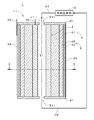
- FIG. 1 is a diagram showing a configuration of a metal-air battery 1 according to an embodiment of the present invention.
- the main body 11 of the metal-air battery 1 has a substantially cylindrical shape centered on the central axis J1, and FIG. 1 shows a cross section of the main body 11 including the central axis J1.
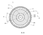
- 2 is a cross-sectional view of the body 11 of the metal-air battery 1 taken along the line II-II in FIG.
- the metal-air battery 1 is a secondary battery including a positive electrode layer 2, a negative electrode layer 3, and an electrolyte layer 4, and the negative electrode layer 3 extends from the central axis J ⁇ b> 1 toward the outside in the radial direction.
- the electrolyte layer 4 and the positive electrode layer 2 are arranged concentrically in order.
- the negative electrode layer 3 (also referred to as a metal electrode) is a cylindrical porous member centered on the central axis J1, and is made of a metal such as magnesium (Mg), aluminum (Al), zinc (Zn), iron (Fe), etc. Or an alloy containing any one of the metals.
- the negative electrode layer 3 is made of zinc and has a cylindrical shape with an outer diameter of 11 millimeters (mm) and an inner diameter of 5 mm when fully charged.
- a negative electrode current collecting terminal 33 is connected to the end of the negative electrode layer 3 in the direction of the central axis J1.
- a space 31 hereinafter referred to as “filling portion 31” surrounded by the inner surface of the negative electrode layer 3 is filled with an electrolytic solution (also referred to as an electrolyte solution).
- the electrolyte layer 4 surrounding the periphery of the negative electrode layer 3 is provided outside the negative electrode layer 3.
- the electrolyte layer 4 has a cylindrical porous member 41, and the inner surface of the porous member 41 faces the outer surface of the negative electrode layer 3. It is preferable that a gap of about 0.5 mm is provided between the negative electrode layer 3 and the porous member 41.
- the electrolyte layer 4 communicates with the filling portion 31 through the pores of the porous negative electrode layer 3, and the porous member 41 is also filled with the electrolytic solution.
- the porous member 41 is formed of ceramic, metal, inorganic material, organic material, or the like, and is preferably a sintered body (that is, integrally molded) of highly insulating ceramic such as alumina, zirconia, or hafnia. . From the viewpoint of preventing an increase in the distance between the negative electrode layer 3 and the positive electrode layer 2 described later while ensuring a certain degree of mechanical strength, the thickness of the porous member 41 is 0.5 mm or more and 4 mm or less. Is preferred.
- the electrolytic solution in the present embodiment is a high-concentration alkaline aqueous solution (for example, an 8M (mol / L) potassium hydroxide (KOH) aqueous solution), and is obtained by saturating zinc oxide as necessary.
- the positive electrode layer 2 (also called an air electrode) includes a porous positive electrode conductive layer 22.
- the positive electrode conductive layer 22 is formed (laminated) on the outer surface of the porous member 41 in the electrolyte layer 4 and has a cylindrical shape.
- the positive electrode conductive layer 22 of the positive electrode layer 2 faces the negative electrode layer 3, and the electrolyte layer 4 containing an electrolytic solution is disposed between the positive electrode conductive layer 22 and the negative electrode layer 3.
- a positive electrode catalyst is supported on the outer surface of the positive electrode conductive layer 22 to form a positive electrode catalyst layer 23.
- An interconnector 24 formed of an alkali-resistant ceramic is provided on a part of the outer surface of the positive electrode catalyst layer 23. The thickness of the interconnector 24 is, for example, about 30 to 300 micrometers ( ⁇ m).
- a positive electrode current collecting terminal 25 is connected to the interconnector 24. Details of the interconnector 24 will be described later.
- a porous layer made of a material having water repellency is formed as a liquid repellent layer 29 in a region not covered with the interconnector 24 on the outer surface of the positive electrode catalyst layer 23.
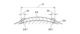
- both end portions 241 hereinafter referred to as “edge portions 241”
- both end portions 241 hereinafter referred to as “edge portions 241”
- the positive electrode conductive layer 22 preferably does not contain carbon (the same applies to the interconnector 24).
- the positive electrode conductive layer 22 is conductive. It is a porous thin conductive film mainly formed of a perovskite oxide (for example, LSCF (LaSrCoFeO 3 )). Such a positive electrode conductive layer 22 is formed by coating the outer surface of the porous member 41 with a perovskite oxide by a slurry coating method, and then baking it.
- the positive electrode conductive layer 22 may be formed by a hydrothermal synthesis method, CVD (Chemical Vapor Deposition), PVD (Physical Vapor Deposition), or the like.
- the positive electrode catalyst layer 23 is formed by a catalyst that promotes oxygen reduction reaction, for example, manganese (Mn), nickel (Ni), metal oxide such as cobalt (Co) and LSMF (LaSrMnFeO 3), LSMCF ( LaSrMnCoFeO Examples of the catalyst include perovskite oxides such as 3 ).
- the positive electrode catalyst layer 23 is coated with a perovskite oxide on the outer surface of the positive electrode conductive layer 22 by a slurry coating method, then baked, and further manganese dioxide (MnO 2 ) or the like by a hydrothermal synthesis method. Is preferentially supported.
- the formation of the positive electrode catalyst layer 23 may be performed by a CVD method, a PVD method, or the like.
- the metal-air battery 1 forms an interface between air and the electrolyte near the porous positive electrode catalyst layer 23.
- disk-shaped blocking members 51 are fixed to both end surfaces (upper end surface and lower end surface in FIG. 1) of the negative electrode layer 3, the electrolyte layer 4, and the positive electrode layer 2 in the central axis J1 direction.
- the A through hole 511 is provided in the center of each closing member 51, and the through hole 511 opens toward the filling portion 31.
- the liquid repellent layer 29 and the closing member 51 prevent the electrolyte solution in the main body 11 from leaking outside from the through hole 511.
- the supply / recovery unit 6 includes an electrolytic solution storage tank and a pump, and recovers the electrolytic solution in the filling unit 31 to the storage tank at a flow rate (volume per unit time) indicated by a control unit (not shown). At the same time, the electrolytic solution in the storage tank can be supplied to the filling unit 31 at the same flow rate.
- the electrolytic solution can be circulated between the filling unit 31 and the storage tank of the supply and recovery unit 6.
- the supply and recovery unit 6 is provided with a filter, and unnecessary substances contained in the electrolytic solution are removed by the filter when the electrolytic solution is circulated.
- the central axis J1 of the main body 11 is parallel to the vertical direction (gravity direction), and the through hole 511 connected to the recovery pipe 62 is a through hole connected to the supply pipe 61. It is located vertically below 511.
- the supply pipe 61 and the recovery pipe 62 are provided with a supply valve and a recovery valve (not shown). In normal operation in this operation example, the electrolyte solution is circulated at a constant flow rate.
- the supply valve and the recovery valve can be regarded as a part of the supply recovery unit 6.
- the central axis J1 of the metal-air battery 1 does not necessarily need to be parallel to the vertical direction.
- the metal-air battery 1 may be arranged so that the central axis J1 is parallel to the horizontal direction.
- the negative current collector terminal 33 and the positive current collector terminal 25 are electrically connected via a load (for example, a lighting fixture).
- the metal contained in the negative electrode layer 3 is oxidized to generate metal ions, and the electrons are supplied to the positive electrode layer 2 via the negative electrode current collector terminal 33, the load, the positive electrode current collector terminal 25, and the interconnector 24.
- oxygen in the air that has passed through the liquid repellent layer 29 is reduced by the electrons supplied from the negative electrode layer 3 and is eluted into the electrolyte as hydroxide ions (OH ⁇ ).
- the oxygen reduction reaction is promoted by the positive electrode catalyst.
- the electrolytic solution is circulated by the supply and recovery unit 6, and the electrolytic solution (hereinafter also referred to as “lower through-hole 511”) in the vicinity of the lower through-hole 511.
- the electrolytic solution (hereinafter also referred to as “lower through-hole 511”) in the vicinity of the lower through-hole 511.
- Most of the electrolyte solution is in the filling portion 31, but the electrolyte solution in the negative electrode layer 3 and the electrolyte layer 4 is also slightly contained.) Is recovered from the through hole 511.
- a part of the electrolytic solution supplied into the filling portion 31 from the upper through hole 511 (hereinafter also referred to as “upper through hole 511”) passes through the pores of the negative electrode layer 3 to the electrolyte layer 4 ( It also diffuses into the porous member 41).
- the electrolyte solution from the supply and recovery unit 6 is also mixed in the electrolyte layer 4.
- the electrolyte contained in the electrolyte layer 4 is gradually replaced with the electrolyte in the storage tank of the supply and recovery unit 6.
- the operation of sequentially collecting a predetermined amount of electrolyte from the lower through-hole 511 and supplying the same amount of electrolyte from the upper through-hole 511 may be repeated.
- the electrolytic solution contained in the electrolyte layer 4 is replaced with the electrolytic solution in the storage tank of the supply and recovery unit 6 while discharging or charging.
- the electrolyte solution in the main body 11 is exchanged (mixing of the deteriorated electrolyte solution and a new electrolyte solution) while discharging or charging.
- the electrolytic solution in the main body 11 may be exchanged by stopping discharging or charging.
- the electrolytic solution may be supplied from the lower through-hole 511 into the filling portion 31 and the electrolytic solution may be recovered from the upper through-hole 511. In this case, the metal-air battery 1 can be reliably filled with the electrolytic solution.
- the interconnector 24 is formed by firing ceramic particles such as metal oxide having alkali resistance and high conductivity.
- the ceramic forming the interconnector 24 preferably has a conductivity of 1 Siemens per centimeter (S / cm) or more (eg, 10,000 S / cm or less) at room temperature (27 ° C.).
- An example is a perovskite oxide represented by LaSrCrFeO 3 .
- the perovskite oxide represented by ABO 3 La is used for the A site, and a part thereof is partially substituted with Sr, Ca, Ba or the like as required, and further, Co, Mn is used for the B site.
- the ceramic include those using Cr, Cr, Ni, and the like, and partially using Fe as necessary.
- the interconnector 24 is required to be dense, and particles having a relatively small particle diameter are used for forming the interconnector 24.
- the average particle diameter of the ceramic particles is preferably 5 ⁇ m or less (for example, 0.01 ⁇ m or more), whereby a dense (not porous) interconnector 24 in which pores between the particles are filled in high-temperature firing. Can be easily formed.
- the interconnector 24 can be formed using a doctor blade method, a rolling method, a pressing method, a casting method, an ink jet method, a slurry coating method, a printing method, or the like.
- a slurry is prepared by adding ceramic particles, which are raw materials for the interconnector 24, to a solution in which alcohol, a dispersant and a binder are mixed, and a positive electrode layer 2 is formed on the outer surface.
- the porous member 41 (hereinafter referred to as “target member”) is immersed in the slurry stored in the container.
- interconnector 24 is formed on the outer side surface of the target member, cap members are attached to both end surfaces of the target member, and a region other than the region where the interconnector 24 is to be formed is formed by masking tape or the like. Covered.
- an interconnector may be formed on the plate-shaped target member.
- ethanol or the like can be used as the alcohol, and not only pure ethanol but also a mixed solvent containing ethanol as a main ingredient may be used.
- a mixed solvent containing ethanol as a main ingredient may be used.
- an organic solvent which does not easily volatilize is preferable.
- 2- (2-n-butoxyethoxy) ethyl acetate or the like can be used.
- An example of the binder is ethyl cellulose, and the addition amount is preferably 2.5 to 7.0 mass percent (wt%). The viscosity of the slurry is adjusted by the amount of ceramic particles added and the amount of binder added.
- the amount of ceramic particles added to the solution is preferably 20 to 40 wt%.
- the addition amount of the ceramic particles is less than 20 wt%, the ceramic particles applied by one dipping are reduced, and depending on the thickness of the interconnector 24, it is necessary to repeat dipping and drying many times.
- the amount of ceramic particles added is more than 40 wt%, the ceramic particles applied by one immersion increase, but the yield may be lowered due to cracks during drying.
- the viscosity of the slurry is preferably 100 to 500 centipoise (cP).
- cP centipoise
- the viscosity of the slurry is lower than 100 cP, fewer ceramic particles are applied in one immersion, and depending on the thickness of the interconnector 24, it is necessary to repeat the immersion and drying many times.
- the viscosity of the slurry is higher than 500 cP, more ceramic particles are applied by one dipping, but the yield may be lowered due to cracks during drying.
- the target member coated with the slurry is dried at a temperature in the range of room temperature to 40 ° C. for 30 minutes or more, and then dried at a temperature in the range of 60 to 100 ° C. for 90 minutes or more, thereby removing the solvent. .
- a slurry layer having a desired thickness (mainly a ceramic particle layer and hence referred to as “ceramic particle layer” hereinafter) is formed.
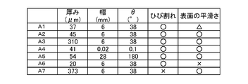
- the thickness of the ceramic particle layer is preferably 30 to 300 ⁇ m. When the thickness of the ceramic particle layer is less than 30 ⁇ m, the resistance in the interconnector 24 increases and the smoothness of the surface of the interconnector 24 decreases.
- the yield may be lowered due to cracking during firing described later.
- the binder is removed by baking at a high temperature, and the slurry application and baking are repeated a plurality of times. May be.
- the interconnector 24 is formed in an angle range of 0.1 ° or more and 180 ° or less around the center axis (center axis J1 of the metal-air battery 1) of the target member.
- the ceramic particle layer is preferably formed in consideration of the change in size due to the above. That is, as shown in FIG. 2, an angle ⁇ formed by two lines connecting one end and the other end of the interconnector 24 and the central axis J1 in the circumferential direction around the central axis J1 is (0.1 ° ⁇ ⁇ ⁇ 180 °) is preferable. In the more preferable interconnector 24, (0.1 ° ⁇ ⁇ ⁇ 60 °) is satisfied.
- the angle ⁇ is preferably 10 ° or more. From the viewpoint of securing an effective area (area for taking in air) of the positive electrode layer 2, the angle ⁇ is preferably small.
- the diameter of the target member is, for example, 10 mm or more and 300 mm or less, and is 16 mm in the present embodiment.
- the ceramic particle layer having such a width can be formed by an inkjet method, a screen printing method, or the like.
- the firing temperature of the target member is, for example, 1000 to 1500 ° C., and the holding time of the firing temperature is preferably about 1 to 5 hours. Since the firing conditions vary depending on the type of ceramic particles, the average particle diameter, and the like, the conditions for obtaining the dense interconnector 24 are appropriately selected.
- water repellent material is applied to the outer surface of the target member by a wet method such as a slurry coating method or a spray coating method.
- water repellent materials include polytetrafluoroethylene (PTFE), tetrafluoroethylene / perfluoroalkyl vinyl ether copolymer (PFA), tetrafluoroethylene / hexafluoropropylene copolymer (FEP), tetrafluoroethylene / hexa At least of fluoropropylene / perfluoroalkyl vinyl ether copolymer (EPE), polychloro-trifluoroethylene (PCTFE), tetrafluoroethylene-ethylene copolymer (ETFE) and chlorotrifluoroethylene-ethylene copolymer (ECTFE) Fluorine resin fine particles (fluorine fine particles) including one can be used.
- a dispersion (dispersion) is prepared by dispersing the fluororesin fine particles together with a surfactant in a liquid dispersion medium.
- the viscosity of the dispersion is adjusted by adding polyethylene oxide as a thickener to the dispersion.
- the amount of fluororesin fine particles added is preferably 10 to 40 wt%. When the addition amount of the fluororesin fine particles is less than 10 wt%, the amount of the fluororesin fine particles is insufficient and the uniform liquid repellent layer 29 is not formed, and the water pressure resistance is lowered.
- the addition amount of the thickener is preferably 0 to 4 wt%.
- the viscosity of the dispersion becomes too high, and the liquid repellent layer 29 is likely to be cracked or peeled off.
- the uniformity is lowered.
- the liquid repellent layer becomes thick and the gas permeability is lowered.
- the viscosity of the dispersion is preferably 1 to 1000 cP, more preferably 5 to 500 cP.
- a nonionic polymer having a molecular weight of 1000 or more is used as the surfactant.
- the nonionic polymer surfactant preferably has a small influence on the dispersibility of the fluororesin fine particles.
- One or a mixture of two or more of amines and polyoxyethylene alkyl alkanolamides are included in the dispersion as the nonionic polymer surfactant.
- dispersion layer a dispersion layer
- the dispersion does not necessarily need to contain a nonionic polymer surfactant.
- the dispersion may contain a cationic surfactant or an anionic surfactant in addition to the nonionic polymer surfactant.
- liquid repellent layer 29 is formed on the outer surface of the cylindrical target member on which the interconnector 24 is formed, cap members are attached to both end surfaces of the target member.
- a central portion (a portion excluding the edge portion 241) is covered with a masking tape or the like.
- the edge part 241 of the interconnector 24 is in an exposed state.
- the target member is immersed in the dispersion stored in the container, and the dispersion adheres to the region excluding the interconnector 24 and the edge portion 241 of the interconnector 24 on the outer surface of the target member.
- the main surface opposite to the surface on which the interconnector 24 is formed is also covered with a masking tape or the like.
- the target member on which the dispersion layer is formed is further dried at, for example, 80 ° C. after drying at around room temperature.
- the drying time in the vicinity of room temperature is a time that does not cause dripping, and is, for example, about 30 minutes.
- the drying at 80 ° C. is for evaporating the moisture contained in the target member as slowly as possible, and it is possible to dry at a temperature lower than 80 ° C. over a longer time.
- the drying time at 80 ° C. is preferably 2 hours or more.
- the firing of the target member after the drying treatment may be performed at a processing temperature not less than 100 ° C. lower than the melting point of the fluororesin fine particles and not higher than 70 ° C. higher than the melting point of the fluororesin fine particles. preferable.
- the processing temperature (firing temperature) is not less than 100 ° C. lower than the melting point of the fluororesin fine particles, the time required from the start of heating to the fusion of the fluororesin fine particles can be relatively short, The time required for manufacturing the liquid repellent layer 29 can be shortened.
- the treatment temperature is not higher than 70 ° C. higher than the melting point of the fluororesin fine particles, the porous structure can be easily controlled to obtain a desired average pore diameter.
- the liquid-repellent layer 29 is formed as a porous structure by applying fine particles of fluororesin on the surface of the positive electrode layer 2 on which the interconnector 24 is provided and firing.
- the melting point is 260 ° C.
- the treatment temperature is preferably 160 ° C. or more and 330 ° C. or less.
- the fluororesin is PTFE
- the melting point thereof is 327 ° C.
- the treatment temperature is preferably 227 ° C. or higher and 397 ° C. or lower.
- the melting point of PFA is 310 ° C
- the melting point of PCTFE is 220 ° C
- the melting point of ETFE is 270 ° C
- the melting point of ECTFE is 245 ° C
- the melting point of the material is A processing temperature within the temperature range is employed.
- the treatment temperature is more preferably at least 80 ° C.
- the temperature is lower than the melting point of the fine particles by 60 ° C. and lower than the temperature higher by 50 ° C. than the melting point of the fluororesin fine particles.
- the temperature increase rate in the baking treatment is within a range of 0.1 to 10 ° C. per minute (that is, 0.1 to 10 ° C./min).
- the rate of temperature increase is greater than 10 ° C./min, there is a risk that cracking or peeling will occur and the yield will be lowered.
- the rate of temperature increase is less than 0.1 ° C./min, the firing process takes excessive time. More preferably, the temperature rising rate is 0.5 to 5 ° C./min.
- the width of the entire interconnector 24 in the width direction is defined as the direction connecting both ends of the interconnector 24 in the circumferential direction (see FIG. 3 is 6 mm, the width in the width direction in which the liquid repellent layer 29 overlaps each edge portion 241 of the interconnector 24 (an arrow with a symbol W in FIG. 3). And is hereinafter referred to as “overlap width”) is preferably 0.1 mm or more and 2.9 mm or less, and more preferably 0.5 mm or more and 2.5 mm or less.
- the ratio of the width in which the liquid repellent layer 29 overlaps the interconnector 24 to the entire width of the interconnector 24 is (0.03 ⁇ (2W /A) ⁇ 0.97) is preferable, and (0.17 ⁇ (2 W / A) ⁇ 0.83) is more preferable.
- the overlap width W is smaller than 0.1 mm (that is, ((2 W / A) ⁇ 0.03))
- the liquid repellent is caused by the pressure from the inside applied to the interface between the liquid repellent layer 29 and the interconnector 24.
- the layer 29 may be peeled off.
- the overlap width W is larger than 2.9 mm (that is, ((2 W / A)> 0.97)), it is difficult to connect the positive electrode current collector terminal 25 to the interconnector 24.
- the entire width of the interconnector 24 is preferably 2.7 mm or less, and more preferably 2 mm or less.
- the value of (2W / A) preferably satisfies ((2W / A) ⁇ 0.90), and more preferably satisfies ((2W / A) ⁇ 0.67).
- the interconnector 24 formed of an alkali-resistant ceramic is provided on the surface of the porous positive electrode layer 2 opposite to the surface in contact with the electrolyte layer 4. It is done. Furthermore, a liquid repellent layer 29 having liquid repellency with respect to the electrolytic solution is provided on the surface of the positive electrode layer 2 on which the interconnector 24 is provided, and covers the surface together with the interconnector 24.
- the liquid repellent layer 29 covers the edge portion 241 of the interconnector 24, leakage of the electrolyte can be prevented more reliably.
- the processing for winding and fixing the nickel mesh or the like becomes complicated.
- the interconnector 24 as a current collector, the manufacturing process of the metal-air battery 1 can be simplified, and the manufacturing cost of the metal-air battery 1 can be reduced.
- the positive electrode layer 2 is disposed outside the negative electrode layer 3, and the interconnector 24 is formed on the outer surface of the positive electrode layer 2.
- the interconnector 24 can be formed easily.
- the effective area for taking air into the metal-air battery 1 can be increased.
- the degree of freedom in selecting the material used as the liquid repellent layer 29 is increased. be able to.
- a cylindrical porous alumina support (corresponding to the porous member 41) having an outer diameter of 16 mm, an inner diameter of 12 mm, and a length of 70 mm was prepared, and a perovskite oxide LaSrMnCoFeO 3 (on the outer surface of the porous alumina support).
- a perovskite oxide LaSrMnCoFeO 3 (on the outer surface of the porous alumina support).
- the positive electrode catalyst layer 23) was prepared by a slurry coating method to prepare a target member.
- the target member is used for the evaluation of the interconnector (and the liquid repellent layer), the layer corresponding to the positive electrode conductive layer 22 is omitted.
- the average pore diameter of the target member is 2.5 ⁇ m, and the nitrogen (N 2 ) gas permeation amount is 2500 m 3 / (m 2 ⁇ h ⁇ atm).
- an angle ⁇ (see FIG. 2) that satisfies (0.1 ° ⁇ ⁇ ⁇ 180 °) and a length in the central axis direction of 60 mm (interconnector 24 is formed).
- Masking tape was affixed to the area excluding the planned area.
- the target member was immersed in the slurry stored in the container for 1 minute, and subsequently dried at 35 ° C. for 30 minutes and at 80 ° C. for 90 minutes. After repeating the above operation a plurality of times, the masking tape was peeled off and baked at 1300 ° C. for 4 hours to form an interconnector on the target member.
- samples B1 to B27 were prepared. Samples B1 to B27 were evaluated for the gas permeation performance of the liquid repellent layer by a nitrogen gas permeation test, the water pressure resistance performance of the liquid repellent layer by a water pressure resistance test, and the presence or absence of cracks / peeling of the liquid repellent layer by visual observation.
- the gas permeability is less than 30 m 3 / (m 2 ⁇ h ⁇ atm) ⁇ , 30 m 3 / (m 2 ⁇ h ⁇ atm) or more and less than 100 m 3 / (m 2 ⁇ h ⁇ atm) ⁇ , 100 m 3 / ( m 2 ⁇ h ⁇ atm) or more and less than 200 m 3 / (m 2 ⁇ h ⁇ atm) is given as ⁇ , and 200 m 3 / (m 2 ⁇ h ⁇ atm) or more as ⁇ .
- Samples B1 to B21 had good gas permeation performance and water pressure resistance, and neither cracking nor peeling occurred.
- sample B22 since the concentration of the fluorine compound (FEP) was low, the water pressure resistance was low.
- sample B23 the gas permeation performance was low due to the high concentration of the fluorine compound.
- sample B24 since the firing temperature was too low, both the gas permeation performance and the water pressure resistance performance were low.
- sample B25 the firing temperature was too high, so the water pressure resistance was low.
- sample B26 since the overlap width W was too small, peeling occurred and the water pressure resistance was lowered.
- Sample B27 is satisfactory in performance and appearance, but is not preferable because the overlap width W is too large.
- the conditions at the time of producing the samples B1 to B21 are preferable.
- the conditions at the time of producing the samples B22 to B27 may be used.
- the metal-air battery 1 can be variously modified.
- the metal-air battery 1 does not necessarily have a cylindrical shape.
- the metal-air battery 1 may have a polygonal cross section perpendicular to the central axis J1.
- the negative electrode layer 3 is not limited to a cylindrical shape, and may be a cylindrical shape.
- the positive electrode layer 2 and the negative electrode layer 3 may be plate-shaped.
- the interconnector 24 and the liquid repellent layer 29 are on the main surface opposite to the main surface in contact with the electrolyte layer 4 in the positive electrode layer 2. Is provided.
- the interconnector 24 formed of alkali-resistant ceramic can be used in various metal-air batteries.
Landscapes
- Engineering & Computer Science (AREA)
- Manufacturing & Machinery (AREA)
- Chemical & Material Sciences (AREA)
- Chemical Kinetics & Catalysis (AREA)
- Electrochemistry (AREA)
- General Chemical & Material Sciences (AREA)
- Hybrid Cells (AREA)
- Connection Of Batteries Or Terminals (AREA)
Abstract
Description
2 正極層
3 負極層
4 電解質層
24 インターコネクタ
29 撥液層
241 エッジ部
Claims (4)
- 金属空気電池であって、
負極層と、
前記負極層に対向する多孔質の正極層と、
前記負極層と前記正極層との間に配置されるとともにアルカリ性の電解液を含む電解質層と、
前記正極層において前記電解質層に接する面とは反対側の面上に設けられ、耐アルカリ性を有するセラミックにて形成されるインターコネクタと、
前記電解液に対する撥液性を有し、前記正極層の前記インターコネクタが設けられた面を前記インターコネクタと共に覆う撥液層と、
を備える。 - 請求項1に記載の金属空気電池であって、
前記インターコネクタを形成する前記セラミックが、1ジーメンス毎センチメートル以上の導電率を有する。 - 請求項1または2に記載の金属空気電池であって、
前記撥液層が、フッ素樹脂の微粒子を前記正極層の前記インターコネクタが設けられた面上に付与し、前記微粒子の融点よりも100℃だけ低い温度以上、かつ、前記融点よりも70℃だけ高い温度以下の処理温度にて焼成することにより、多孔質構造として形成される。 - 請求項1ないし3のいずれかに記載の金属空気電池であって、
前記撥液層が、前記インターコネクタのエッジ部を覆う。
Priority Applications (2)
| Application Number | Priority Date | Filing Date | Title |
|---|---|---|---|
| JP2015508317A JP6259815B2 (ja) | 2013-03-29 | 2014-03-17 | 金属空気電池 |
| US14/779,206 US9899654B2 (en) | 2013-03-29 | 2014-03-17 | Metal-air battery |
Applications Claiming Priority (2)
| Application Number | Priority Date | Filing Date | Title |
|---|---|---|---|
| JP2013071051 | 2013-03-29 | ||
| JP2013-071051 | 2013-03-29 |
Publications (1)
| Publication Number | Publication Date |
|---|---|
| WO2014156763A1 true WO2014156763A1 (ja) | 2014-10-02 |
Family
ID=51623744
Family Applications (1)
| Application Number | Title | Priority Date | Filing Date |
|---|---|---|---|
| PCT/JP2014/057119 Ceased WO2014156763A1 (ja) | 2013-03-29 | 2014-03-17 | 金属空気電池 |
Country Status (3)
| Country | Link |
|---|---|
| US (1) | US9899654B2 (ja) |
| JP (1) | JP6259815B2 (ja) |
| WO (1) | WO2014156763A1 (ja) |
Cited By (1)
| Publication number | Priority date | Publication date | Assignee | Title |
|---|---|---|---|---|
| WO2016152338A1 (ja) * | 2015-03-24 | 2016-09-29 | 日立造船株式会社 | 金属空気電池 |
Families Citing this family (1)
| Publication number | Priority date | Publication date | Assignee | Title |
|---|---|---|---|---|
| KR102429170B1 (ko) * | 2017-09-04 | 2022-08-03 | 현대자동차주식회사 | 리튬 공기 배터리 장치 |
Citations (6)
| Publication number | Priority date | Publication date | Assignee | Title |
|---|---|---|---|---|
| JPH0950828A (ja) * | 1995-08-04 | 1997-02-18 | Matsushita Electric Ind Co Ltd | 角形空気電池 |
| JPH11191440A (ja) * | 1997-12-26 | 1999-07-13 | Sony Corp | 空気極及びこれを用いた空気電池 |
| JP2006142275A (ja) * | 2004-10-21 | 2006-06-08 | Matsushita Electric Ind Co Ltd | 酸素透過膜、酸素透過シート、およびこれらを含む電池 |
| WO2011152464A1 (ja) * | 2010-06-04 | 2011-12-08 | 日立造船株式会社 | 金属空気電池 |
| JP2011253789A (ja) * | 2010-06-04 | 2011-12-15 | Hitachi Zosen Corp | 金属空気電池 |
| JP2013222610A (ja) * | 2012-04-17 | 2013-10-28 | Hitachi Zosen Corp | 金属空気電池 |
Family Cites Families (7)
| Publication number | Priority date | Publication date | Assignee | Title |
|---|---|---|---|---|
| US3554810A (en) | 1967-04-12 | 1971-01-12 | Solomon Zaromb | Metal-oxygen power source |
| JP4009786B2 (ja) | 1996-04-23 | 2007-11-21 | 東芝電池株式会社 | 円筒型空気電池 |
| JP4537292B2 (ja) * | 2005-08-29 | 2010-09-01 | 株式会社日立製作所 | 円筒形燃料電池 |
| US20070141440A1 (en) * | 2005-12-21 | 2007-06-21 | General Electric Company | Cylindrical structure fuel cell |
| KR100922350B1 (ko) * | 2007-10-09 | 2009-10-19 | 삼성에스디아이 주식회사 | 이차 전지 및 전지 모듈 |
| US8338025B2 (en) * | 2010-08-09 | 2012-12-25 | Siemens Aktiengesellschaft | Self-sealed metal electrode for rechargeable oxide-ion battery cells |
| WO2013161253A1 (en) * | 2012-04-25 | 2013-10-31 | Hitachi Zosen Corporation | Functional porous material, metal-air battery, and method for manufacturing functional porous material |
-
2014
- 2014-03-17 WO PCT/JP2014/057119 patent/WO2014156763A1/ja not_active Ceased
- 2014-03-17 US US14/779,206 patent/US9899654B2/en not_active Expired - Fee Related
- 2014-03-17 JP JP2015508317A patent/JP6259815B2/ja not_active Expired - Fee Related
Patent Citations (6)
| Publication number | Priority date | Publication date | Assignee | Title |
|---|---|---|---|---|
| JPH0950828A (ja) * | 1995-08-04 | 1997-02-18 | Matsushita Electric Ind Co Ltd | 角形空気電池 |
| JPH11191440A (ja) * | 1997-12-26 | 1999-07-13 | Sony Corp | 空気極及びこれを用いた空気電池 |
| JP2006142275A (ja) * | 2004-10-21 | 2006-06-08 | Matsushita Electric Ind Co Ltd | 酸素透過膜、酸素透過シート、およびこれらを含む電池 |
| WO2011152464A1 (ja) * | 2010-06-04 | 2011-12-08 | 日立造船株式会社 | 金属空気電池 |
| JP2011253789A (ja) * | 2010-06-04 | 2011-12-15 | Hitachi Zosen Corp | 金属空気電池 |
| JP2013222610A (ja) * | 2012-04-17 | 2013-10-28 | Hitachi Zosen Corp | 金属空気電池 |
Cited By (5)
| Publication number | Priority date | Publication date | Assignee | Title |
|---|---|---|---|---|
| WO2016152338A1 (ja) * | 2015-03-24 | 2016-09-29 | 日立造船株式会社 | 金属空気電池 |
| JP2016181400A (ja) * | 2015-03-24 | 2016-10-13 | 日立造船株式会社 | 金属空気電池 |
| CN107408745A (zh) * | 2015-03-24 | 2017-11-28 | 日立造船株式会社 | 金属空气电池 |
| CN107408745B (zh) * | 2015-03-24 | 2019-10-11 | 日立造船株式会社 | 金属空气电池 |
| US10505171B2 (en) | 2015-03-24 | 2019-12-10 | Hitachi Zosen Corporation | Metal-air battery |
Also Published As
| Publication number | Publication date |
|---|---|
| JP6259815B2 (ja) | 2018-01-10 |
| JPWO2014156763A1 (ja) | 2017-02-16 |
| US9899654B2 (en) | 2018-02-20 |
| US20160072114A1 (en) | 2016-03-10 |
Similar Documents
| Publication | Publication Date | Title |
|---|---|---|
| JP6602773B2 (ja) | 電気化学素子、固体酸化物形燃料電池セル、およびこれらの製造方法 | |
| US9634323B2 (en) | Electrode, metal-air battery, and electrode manufacturing method | |
| WO2011152464A1 (ja) | 金属空気電池 | |
| JP2016066616A (ja) | 電気化学素子、固体酸化物形燃料電池セル、およびこれらの製造方法 | |
| JP5904854B2 (ja) | 金属空気電池 | |
| CN104704665A (zh) | 电极组件及其制备方法 | |
| JP6562739B2 (ja) | 電極および金属空気二次電池 | |
| JP5773699B2 (ja) | 金属空気電池 | |
| JP6250551B2 (ja) | 機能性多孔体の製造方法 | |
| JPWO2016043315A1 (ja) | 電気化学素子、固体酸化物形燃料電池セル、およびこれらの製造方法 | |
| JP6588716B2 (ja) | 金属空気電池 | |
| CN105593413B (zh) | 用于使材料层沉积到燃料电池或电解池的金属支承体上的方法 | |
| JP6259815B2 (ja) | 金属空気電池 | |
| JP2012104273A (ja) | 金属空気電池 | |
| JP6596213B2 (ja) | 金属空気電池 | |
| JP6068228B2 (ja) | セパレータ、金属空気二次電池およびセパレータの製造方法 | |
| JP6166929B2 (ja) | 金属空気二次電池 | |
| JP2017208197A (ja) | 金属空気二次電池 | |
| JP2016162700A (ja) | 燃料電池用アノードおよび燃料電池単セル | |
| JP2015185235A (ja) | 電極および二次電池 | |
| WO2016080115A1 (ja) | 金属空気電池 | |
| JP2015188870A (ja) | 二酸化マンガン担持方法、多孔質セラミック部材および金属空気二次電池 | |
| JP2019207885A (ja) | 金属空気電池 |
Legal Events
| Date | Code | Title | Description |
|---|---|---|---|
| 121 | Ep: the epo has been informed by wipo that ep was designated in this application |
Ref document number: 14772862 Country of ref document: EP Kind code of ref document: A1 |
|
| ENP | Entry into the national phase |
Ref document number: 2015508317 Country of ref document: JP Kind code of ref document: A |
|
| WWE | Wipo information: entry into national phase |
Ref document number: 14779206 Country of ref document: US |
|
| NENP | Non-entry into the national phase |
Ref country code: DE |
|
| 122 | Ep: pct application non-entry in european phase |
Ref document number: 14772862 Country of ref document: EP Kind code of ref document: A1 |