WO2014156164A1 - モータ駆動装置のサーボ調整方法 - Google Patents
モータ駆動装置のサーボ調整方法 Download PDFInfo
- Publication number
- WO2014156164A1 WO2014156164A1 PCT/JP2014/001769 JP2014001769W WO2014156164A1 WO 2014156164 A1 WO2014156164 A1 WO 2014156164A1 JP 2014001769 W JP2014001769 W JP 2014001769W WO 2014156164 A1 WO2014156164 A1 WO 2014156164A1
- Authority
- WO
- WIPO (PCT)
- Prior art keywords
- function
- index
- command
- stiffness
- setting
- Prior art date
Links
Images


Classifications
-
- H—ELECTRICITY
- H02—GENERATION; CONVERSION OR DISTRIBUTION OF ELECTRIC POWER
- H02P—CONTROL OR REGULATION OF ELECTRIC MOTORS, ELECTRIC GENERATORS OR DYNAMO-ELECTRIC CONVERTERS; CONTROLLING TRANSFORMERS, REACTORS OR CHOKE COILS
- H02P23/00—Arrangements or methods for the control of AC motors characterised by a control method other than vector control
- H02P23/14—Estimation or adaptation of motor parameters, e.g. rotor time constant, flux, speed, current or voltage
-
- H—ELECTRICITY
- H02—GENERATION; CONVERSION OR DISTRIBUTION OF ELECTRIC POWER
- H02P—CONTROL OR REGULATION OF ELECTRIC MOTORS, ELECTRIC GENERATORS OR DYNAMO-ELECTRIC CONVERTERS; CONTROLLING TRANSFORMERS, REACTORS OR CHOKE COILS
- H02P6/00—Arrangements for controlling synchronous motors or other dynamo-electric motors using electronic commutation dependent on the rotor position; Electronic commutators therefor
- H02P6/04—Arrangements for controlling or regulating the speed or torque of more than one motor
Definitions
- the present invention relates to a servo adjustment method in a motor drive device that controls a servo motor.
- the current motor drive system has external commands for servo motors.
- various automatic adjustment functions are installed.
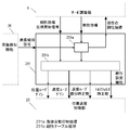
- FIG. 33 is a block diagram of a conventional motor drive device.
- the basic function to drive and control the motor is composed of single line blocks connected by solid lines in FIG.
- the command selection unit 21 selects either an internal position command or an external position command output by a test operation function 211 described later, and outputs the selected position command to the command response setting unit 22.
- the command response setting unit 22 performs a filter calculation process on the selected position command, and then outputs the filtered position command to the position speed control unit 23.
- the position speed control unit 23 performs a feedback control calculation represented by PID (proportional, integral, derivative) control from the post-filter position command and the motor position information from the encoder 4 so that the position deviation becomes zero. Output a correct torque command.
- PID proportional, integral, derivative
- the load characteristic compensator 24 performs a scaling process to absorb the influence of the inertia according to the total inertia of the motor 3 and the load 5 with respect to the torque command output from the position / speed controller 23, thereby reducing the load inertia. Absorb the difference. Further, a compensation torque command is generated by estimating the friction torque of the motor 3 and the load 5 from the motor position information from the encoder 4 and adding in advance.
- the resonance suppression unit 25 obtains the result of passing through a notch filter or low-pass filter process for removing a specific frequency component from the compensated torque command so as not to excite vibration caused by the resonance characteristics of the motor 3 and the load 5. Output as torque command.
- the motor 3 is controlled so as to output the torque according to the filtered torque command through the current control and the power circuit (not shown) that receive the filtered torque command.
- the movement of the motor 3 is transmitted to the connected load 5 and the encoder 4, and is fed back to the motor drive device 92 as motor position information through the encoder 4.
- the trial operation function 211 generates a positive and negative reciprocating operation pattern of a certain amount with a triangular wave having an acceleration / deceleration with a certain inclination inside the motor driving device 92 as disclosed in Patent Document 1, for example. More generally, parameters such as a movement amount, maximum speed, acceleration time, deceleration time, and stop time are set in the motor drive device 92 from the outside.
- the test operation function 211 is a function for automatically calculating a command pattern in real time by NC (numerical control) calculation processing built in the motor drive device 92 and generating an internal position command for every fixed period.
- the operation of the command selection unit 21 can also be specified from the test run function 211 by transmitting additional information requesting the selection of the internal position command to the command selection unit 21 together with the internal position command.
- the command response setting function 221 gives, for example, one index called a stiffness value from the outside of the motor drive device 92 and determines the responsiveness of the position command from a table built in the motor drive device 92 as disclosed in Patent Document 2. Determine the cutoff frequency of the prefilter. More generally, the motor drive device 92 is instructed to give finer frequency characteristics by the filter time constant or attenuation ratio of the first-order lag or second-order lag, or the transient of time response such as the rise time, delay time, and overshoot amount. One or a plurality of command response indicators, such as a shape indicating a characteristic, are input. The command response setting function 221 automatically sets one or more parameters of the command response setting unit 22 so that the input / output relationship of the command response setting unit 22 matches the command response index as much as possible.
- the stiffness setting function 231 uses one parameter representing servo stiffness as an index, and multiplies it by a fixed ratio to set the speed proportional gain, speed integral gain, and position proportional gain in conjunction with each other. To do. Further, as described in Patent Document 2 described above, the gain setting of the position / speed control unit may be determined from a table corresponding to the stiffness value. In general, the stiffness setting function 231 inputs one or more stiffness indices, and sets one or more parameters of the position / speed control unit 23 so that the disturbance response of the position / speed control unit 23 matches the stiffness index as much as possible. Set automatically.
- the load characteristic measurement function 241 uses least square estimation from the torque command after filtering to the motor 3, the motor position information from the encoder 4, and the speed / acceleration that is a high-order difference thereof. To automatically estimate the load characteristics.
- the load-related characteristics include friction characteristics such as total inertia of the motor 3 and the load 5, a biased load torque that always works constant, a dynamic friction torque that depends on the operation direction, and a viscous friction torque that is proportional to the operation speed. .
- the load characteristic compensation unit 24 by reflecting the estimation result on the load characteristic compensation unit 24 in real time, the same responsiveness specified by the command response index and the stiffness index can be obtained regardless of what load 5 is connected. Can be made.
- the adaptive filter function 251 automatically adjusts the parameters of the resonance suppression unit 25 so that the high-frequency component extracted from the motor speed is as close to 0 as possible by an adaptive algorithm using a recursive notch filter, as described in Patent Document 4, for example. To do.
- the adaptive filter function 251 extracts a vibration component from the torque command, extracts a vibration component from the difference from the model response, further has a plurality of adaptive filters, and not only the notch frequency but also the width and depth.
- There are variations such as automatically adjusting the sheath Q value.
- the vibration component caused by the resonance characteristics of the motor 3 and the load 5 is extracted by some method, and the filter parameter of the resonance suppression unit 25 is automatically adjusted by an adaptive algorithm that minimizes the difference from the reference input. .
- the oscillation detection function 26 extracts fluctuations from the motor position information from the encoder 4, and compares the threshold value, determines the duration, and the like to oscillate the motor 3 and the load 5. Detect state. When oscillation is detected, the oscillation detection information is transmitted to the stiffness setting function 231 described above, and a stiffness value that narrows the frequency bandwidth of the feedback loop is selected to automatically suppress oscillation.
- the evaluation index measurement function 27 receives input / output data such as the position command output of the command selection unit 21, the motor position output of the encoder 4, and the torque command output of the load characteristic compensation unit 24 as disclosed in Patent Document 7, for example. Measure and store periodically. It is a function for calculating, displaying, and accumulating evaluation values from input / output data corresponding to evaluation indexes such as settling time, overshoot, and torque fluctuation. In any case, it is an important aspect of this function to compress data from a huge amount of motor control information that can be acquired in real time into a small number of evaluation indexes that are more meaningful.
- test run function 211 can be used not only for servo adjustment but also for various purposes such as origin search at the time of mechanism assembly, aging for operation confirmation, and evacuation operation during maintenance work. For this reason, in the trial run function 211, the amount of movement, speed, and acceleration can be customized.
- the operations required for servo adjustment differ from step to step, and knowledge about servo adjustment and various automatic adjustment functions is required to select this operation.
- the command response setting function 221 can shorten the settling time in the positioning control (PTP control) and the tracking error in the trajectory control (CP control) as the command response index increases, but the discrete response of the external position command can be reduced. Restrictions are imposed by the computerization and command resolution settings. In addition, the command response index may be lowered in consideration of machine vibration due to the rigidity of the device itself to which the motor 3 and the load 5 are fixed. This judgment requires understanding of the host device and experience in actual operation. It becomes.
- the rigidity setting function 231 also improves the disturbance suppression characteristics as the rigidity index is increased, and the follow-up error in the CP control can also be reduced.
- how much the rigidity index can be increased greatly depends on the stability of the feedback control of the position / speed control unit 23. For this reason, knowledge about control theory is essential for optimal adjustment.
- the setting of the position / velocity control unit 23, the total inertia of the load characteristic compensation unit 24, and the resonance suppression unit 25 is not set in the correct order, the feedback stability is impaired, and the responsiveness specified by the stiffness index is obtained. Absent. Furthermore, in the worst case, it may become unstable and oscillate.
- the control theory not also know-how regarding the servo adjustment procedure becomes important.
- the load characteristic measurement function 241 is a convenient function that automatically adjusts the total inertia and friction compensation of the load characteristic compensator 24, but is not suitable for applications in which the load characteristic changes sharply.
- Least squares estimation is always enabled for articulated robots, pick and place devices that are subject to large load fluctuations due to direct drive, etc., and devices whose total inertia varies periodically with cam drive. It is not appropriate.
- friction compensation is also not useful for estimating the offset load torque with a single motor because the direction of gravity changes in an articulated robot.
- load characteristic estimation based on the least squares method which is a premise for compensation, is also affected by errors due to operation patterns and nonlinear characteristics. Therefore, knowledge and experience of system identification are required to obtain an optimal estimated value.
- the adaptive filter function 251 automatically adjusts the filter setting of the resonance suppression unit 25, but it is usually assumed that the resonance characteristics do not change sharply.
- the motor that drives the joint close to the fixed side has a resonance characteristic that changes depending on the posture, and therefore it is not appropriate to use the adaptive filter function 251.
- the adaptive filter may malfunction, and it is very risky to always make it effective even with current technology. In that sense, a case-by-case response to the site and the actual product is necessary.
- the oscillation detection function 26 is a convenient function for servo adjustment in which the setting is frequently changed and the operation is tested. However, when the operation is performed during actual operation, the behavior of the load changes thereafter. For this reason, it is necessary to take care in operation that is limitedly effective in situations where oscillation is expected to some extent, such as during servo adjustment.
- the evaluation index measurement function 27 does not affect the basic function for controlling the motor. However, depending on the evaluation index, there are cases where certain restrictions are imposed on the setting of the command pattern and the basic function in order to obtain a correct measurement result.
- the positioning settling time in the PTP control is defined as from the time when the external position command stops to the time when the motor position enters the positioning completion range. However, if the index or stiffness index is low and the next external position command change starts before the motor position enters the positioning complete range, naturally the positioning settling time cannot be measured. Unless the meaning of the evaluation index and the measurement method of the evaluation index measurement function are understood, the result of servo adjustment cannot be determined correctly.
- the motor drive device of the present invention has one of the following five basic functions for motor control.
- the first basic function is a command selection unit that inputs an external position command and an internal position command input from the host device and outputs either as a post-selection position command.
- the second basic function is a command response setting unit that inputs a post-selection position command, performs a filtering process to remove a specific frequency band, and outputs a post-filter position command.
- the third basic function is a position speed control unit that receives the post-filter position command and the motor position information from the encoder and generates a torque command such that the deviation between them is zero.
- the fourth basic function is a load characteristic correction unit that receives the torque command, multiplies the estimated motor and load inertia values, adds the estimated friction torque values of the load, and generates a post-compensation torque command.
- the fifth basic function is a resonance suppression unit that performs a filtering process to remove a specific frequency band from the compensated torque command and outputs the filtered torque command.
- the motor drive device of the present invention includes any of the following seven automatic adjustment functions.
- the first automatic adjustment function is a test operation function that automatically generates an internal position command in accordance with an operation pattern specified by the servo adjustment unit.
- the second automatic adjustment function is a command response setting function that automatically sets the filter characteristics of the command response setting unit in accordance with a command response index specified by the servo adjustment unit.
- the third automatic adjustment function is a rigidity setting function that automatically sets the parameters of the position / speed control unit in accordance with the stiffness index specified by the servo adjustment unit and the oscillation detection signal notified from the oscillation detection function.
- the fourth automatic adjustment function can enable / disable the load characteristic measurement from the servo adjustment unit and enable / disable the reflection of the load characteristic estimation result individually.
- the filtered torque command of the resonance control unit and the motor from the encoder This is a load characteristic measurement function that automatically measures load characteristics from position information and automatically sets a load characteristic compensation unit according to the measurement result.
- the fifth automatic adjustment function is an adaptive filter function that can set the adaptive operation validity / invalidity and the adaptive filter mode from the servo adjustment unit, and automatically set the filter characteristics of the resonance suppression unit according to the adaptive filter mode when valid. .
- the sixth automatic adjustment function enables you to set the oscillation detection enable / disable and oscillation detection level from the servo adjustment unit, automatically measures the oscillation state from the position information from the encoder, and automatically oscillates in conjunction with the stiffness setting function Oscillation detection function to suppress.
- the seventh automatic adjustment function is an evaluation index measurement function that can set a positioning completion range from the servo adjustment unit and automatically measures various evaluation indices from a post-filter position command, motor position information, post-filter torque command, and the like.
- the initial setting step 1 the load characteristic measurement and the command pattern determination 2 are determined, the stiffness index maximum value is determined, and the stiffness index is supported.
- Step 3 for storing the setting of the resonance suppression unit,
- Step 4 for storing the evaluation index for the designated operation by combining the stiffness index and the command response index, and Step 5 for obtaining the final adjustment result from the evaluation index according to the search condition.
- the configuration has one of five steps.
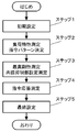
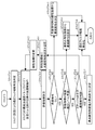
- FIG. 1 is a flowchart showing each step of a servo adjustment method for a motor drive device according to Embodiment 1 of the present invention.
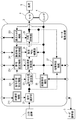
- FIG. 2 is a block diagram of the motor driving apparatus according to the first embodiment.
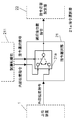
- FIG. 3 is a diagram showing a detailed configuration of the command selection unit in the first embodiment.
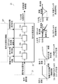
- FIG. 4 is a diagram showing a detailed configuration of the command response setting unit in the first embodiment.
- FIG. 5 is a diagram illustrating a detailed configuration of the position / speed control unit according to the first embodiment.
- FIG. 6 is a diagram illustrating a detailed configuration of another example of the position / speed control unit according to the first embodiment.
- FIG. 7 is a diagram showing a detailed configuration of the load characteristic compensator in the first embodiment.
- FIG. 1 is a flowchart showing each step of a servo adjustment method for a motor drive device according to Embodiment 1 of the present invention.
- FIG. 2 is a block diagram of the motor driving apparatus according to the first embodiment
- FIG. 8 is a diagram showing a detailed configuration of the resonance suppression unit in the first embodiment.
- FIG. 9A is a diagram showing a detailed configuration of the trial operation function in the first embodiment.
- FIG. 9B is a diagram illustrating a command pattern generation example of the command generation unit of the test operation function in the first embodiment.
- FIG. 10 is a diagram showing a detailed configuration of the command response setting function in the first embodiment.
- FIG. 11A is a diagram showing a detailed configuration of a stiffness setting function in the first exemplary embodiment.
- FIG. 11B is a diagram showing an example of a stiffness table of the stiffness setting function in the first exemplary embodiment.
- FIG. 12A is a diagram showing a detailed configuration of the load characteristic measurement function in the first embodiment.
- FIG. 12B is a diagram for explaining a method of deriving an estimated value by the least square estimation process in the first embodiment.
- FIG. 13 is a diagram showing a detailed configuration of the adaptive filter function in the first embodiment.
- FIG. 14 is a diagram showing a detailed configuration of the oscillation detection function in the first embodiment.
- FIG. 15 is a diagram showing a detailed configuration of the evaluation index measurement function in the first embodiment.
- FIG. 16 is a diagram of the operation screen in step 1 of servo adjustment according to the second embodiment of the present invention.
- FIG. 17 is a flowchart showing the procedure of step 1 of servo adjustment in the second embodiment.
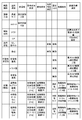
- FIG. 18 is a diagram showing an initial condition determination table in step 1-3 in the second embodiment.
- FIG. 19 is a diagram of the operation screen in step 2 of servo adjustment according to the third embodiment of the present invention.
- FIG. 20 is a flowchart showing the procedure of step 2 of servo adjustment in the third embodiment.
- FIG. 21A is an operation pattern diagram in step 2 of servo adjustment in the third exemplary embodiment.
- FIG. 21B is another operation pattern diagram in step 2 of servo adjustment in the third exemplary embodiment.
- FIG. 22 is a diagram of an operation screen in step 3 of servo adjustment according to the fourth embodiment of the present invention.
- FIG. 23 is a flowchart showing the procedure of step 3 of servo adjustment in the fourth embodiment.
- FIG. 24A is an operation pattern diagram in step 3 of servo adjustment in the fourth embodiment.
- FIG. 24A is an operation pattern diagram in step 3 of servo adjustment in the fourth embodiment.
- FIG. 24B is an operation pattern diagram as another example in step 3 of servo adjustment in the fourth exemplary embodiment.
- FIG. 24C is an operation pattern diagram as still another example in step 3 of servo adjustment in the fourth exemplary embodiment.
- FIG. 25 is a diagram of an operation screen in step 4 of servo adjustment according to the fifth embodiment of the present invention.
- FIG. 26 is a flowchart showing the procedure of step 4 of servo adjustment in the fifth embodiment.
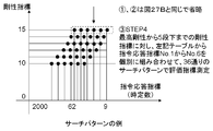
- FIG. 27A is a diagram showing a search pattern table in step 4-1 in the fifth embodiment.
- FIG. 27B is a diagram showing combinations of search patterns in the fifth embodiment.
- FIG. 27C is a diagram showing another combination of search patterns in the fifth embodiment.
- FIG. 28A is an operation diagram at the time of command response measurement in the fifth exemplary embodiment.
- FIG. 28B is an operation diagram at the time of command response measurement in the fifth exemplary embodiment.
- FIG. 28C is an operation diagram at the time of command response measurement in the fifth exemplary embodiment.
- FIG. 29 is a diagram showing an operation screen in step 5 of servo adjustment according to the sixth embodiment of the present invention.
- FIG. 30 is a flowchart showing the procedure of step 5 of servo adjustment in the sixth embodiment.
- FIG. 31 shows a recommended condition table in step 5-1 in the sixth embodiment.
- FIG. 32 is a diagram of a fine adjustment screen in step 5-3 in the sixth embodiment.
- FIG. 33 is a block diagram of a conventional motor driving device.
- FIG. 1 is a flowchart showing each step of a servo adjustment method for a motor drive device according to Embodiment 1 of the present invention.
- FIG. 2 is a block diagram of the motor drive device according to Embodiment 1 of the present invention.
- FIG. 3 to FIG. 15 are diagrams showing a detailed configuration in each block of the motor drive device.
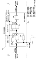
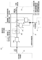
- the motor drive device 2 shown in FIG. 2 has the same outline as that of FIG. 33 in each block, but the input / output to / from the outside of the automatic adjustment function is connected to the servo adjustment unit 6, and control from the servo adjustment unit 6 This is different from the motor drive device 92 shown in FIG. That is, in the present embodiment, the automatic adjustment function of the motor drive device 2 can be collectively controlled by the servo adjustment unit 6.
- the command selection unit 21 receives an internal position command and a command selection signal output from a test run function 211 described later. Then, the command selection unit 21 selects either the external position command or the internal position command based on the command selection signal by the command selector 21a, and is the position command after selection to the command response setting unit 22. Outputs position command after selection.
- the command response setting unit 22 inputs the position command after selection output from the command selection unit 21, performs various filter processes on the position command, and outputs the filtered result as a result.
- the post-filter position command is output as the position command.
- the command response setting unit 22 includes a moving average filter 22a, a first-order lag filter 22b, a second-order filter 22c, and a vibration suppression filter 22d as filter processing.
- the moving average filter 22a performs moving average processing for the number of moving averages specified from a command response setting function 221 described later.
- the first-order lag filter 22b has a step response characteristic of a command response time constant.
- the secondary filter 22c has frequency characteristics defined by the secondary filter frequency and the attenuation ratio.
- the damping filter 22d has a frequency characteristic defined by a damping frequency and a depth.
- FIG. 4 also shows an example of the step response and frequency characteristics of these filters.
- the position / speed control unit 23 receives motor position information from the encoder 4 connected to the motor 3 to be driven, together with the position command after filtering, and a torque command that makes these deviations zero. Is output.
- the position / speed control unit 23 shown in FIG. 5 includes a position proportional process 23a, a speed detection process 23e, a speed proportional process 23b, a speed integration process 23c, a torque filter process 23d, and a speed feedforward process 23f. Yes.
- the position proportional processing 23a multiplies the position deviation by a position loop gain designated by a stiffness setting function 231 described later, and outputs the result.
- the speed detection process 23e detects a motor speed corresponding to the actual speed based on, for example, a difference with respect to the motor position information, a differential calculation, or the like.
- the speed proportional process 23b multiplies the speed deviation by a speed loop gain designated from the stiffness setting function 231 and outputs the result.
- the speed integration process 23c performs speed integration based on a speed loop integration time constant designated by the stiffness setting function 231 and outputs the result.
- the torque filter process 23d applies a first-order lag filter having a torque filter time constant designated by the stiffness setting function 231 to the internal torque command, and outputs the result.
- the speed feedforward process 23f performs a process such as a difference with respect to the filtered position command and outputs the result.
- the position / speed control unit 23 shown in FIG. 5 calculates a position deviation which is a difference between the post-filter position command and the motor position information, and performs position proportional processing 23a on the position deviation to obtain a speed command. . Further, the speed detection process 23e obtains a motor speed corresponding to the actual speed of the motor. Next, a speed deviation, which is the difference between the speed command and the motor speed, is calculated, the speed proportional process 23b and the speed integration process 23c are performed on the speed deviation, and these outputs are added to obtain an internal torque. Get a directive. The internal torque command is subjected to a filter process by the torque filter process 23d to obtain an output torque command. In order to improve responsiveness, the result obtained through the speed feedforward process 23f may be added to the speed command.
- FIG. 6 is a block diagram showing another embodiment of the position / speed control unit 23, and the configuration of FIG. 6 includes processing for generating each command information in a feed-forward manner.
- the position / velocity control unit 23 shown in FIG. 6 includes a feedforward command generation processing 23h and a torque feedforward processing 23g in addition to the processing shown in FIG.
- the feedforward command generation process 23h performs a process combining a first-order difference or a second-order difference and a filter process with respect to the post-filter position command.
- the position / speed control unit 23 shown in FIG. 6 performs the position proportional processing 23a, the speed detection processing 23e, the speed proportional processing 23b, the speed integration, which are the same as those in FIG. A process 23c and a torque filter process 23d are provided.
- a position proportional process 23a is performed on the position deviation to obtain a speed command. Further, the output of the speed feed forward process 23f is added to the speed command. Then, the motor speed is obtained by the speed detection process 23e. Next, a speed deviation, which is the difference between the speed command and the motor speed, is calculated, the speed proportional process 23b and the speed integration process 23c are performed on the speed deviation, and these outputs are added to obtain an internal torque. Get a directive. Further, the output of the torque feed forward process 23g is added to the internal torque command. The internal torque command is subjected to a filter process by the torque filter process 23d to obtain an output torque command.
- the load characteristic compensator 24 performs various types of processing on the torque command, thereby performing a possible friction compensation.
- the load characteristic compensation unit 24 includes an inertia correction process 24a, an offset load compensation process 24b, a dynamic friction compensation process 24c, and a viscous friction compensation process 24d.
- the inertia correction process 24 performs a process of multiplying the torque command by an inertia estimated value designated by a load characteristic measurement function 241 described later. In this way, the inertia correction process 24 performs a scaling process in accordance with the total inertia of the motor 3 and the load 5. Thereby, the difference of the motor equivalent inertia which is different by various loads 5 is absorbed.
- the load characteristic compensation unit 24 compensates for the uneven load by adding the estimated load value specified by the load characteristic measuring function 241 to the torque command.
- the dynamic friction compensation process 24c calculates the motor speed from the motor position information from the encoder 4, and adds or subtracts the estimated dynamic friction value to the torque command according to the motor speed direction.
- the dynamic friction compensation processing 24c performs compensation for dynamic friction by performing such processing.
- the viscous friction compensation process 24d multiplies the motor speed by the estimated value of the viscous friction coefficient and adds it to the torque command.
- the viscous friction compensation processing 24d performs compensation for viscous friction by performing such processing.
- the load characteristic compensator 24 performs friction compensation that can be assumed by these processes, thereby improving the responsiveness and reducing the difference in response depending on the operation direction and speed.
- the load characteristic compensation unit 24 outputs the result of performing various load characteristic compensations as described above as a torque command after compensation.
- the motor speed information used for dynamic friction compensation and viscous friction compensation follows the speed command as long as the position / speed control unit 23 operates. For this reason, if a speed command that can be calculated from a difference in position command or the like is used instead of the motor speed, the compensation value may be stabilized because it is not affected by load fluctuations.
- the resonance suppression unit 25 performs a filtering process to remove specific frequency components so as not to excite vibrations caused by resonance characteristics with the load 5 connected to the motor 3.
- the resonance suppression unit 25 includes a secondary filter 25a and a first notch filter 25c, a second notch filter 25d, a third notch filter 25e, and a fourth notch filter 25f as a plurality of notch filter processes.
- the secondary filter 25a performs a filter process specified by a secondary filter frequency and an attenuation ratio specified by an adaptive filter function 251 described later.
- each notch filter performs notch filter processing for attenuating a specific frequency band with the notch filter frequency / width / depth specified by the adaptive filter function 251.
- the resonance suppression unit 25 outputs the filtered output as a post-filter torque command that is a post-filter torque command.
- FIG. 8 also shows an example of the step response and frequency characteristics of these filters.
- the voltage / current to the motor 3 is controlled by current control or a power circuit (not shown) so that the output torque of the motor 3 changes according to the post-filter torque command, and the load 5 connected to the motor 3 operates. Will do.
- the test run function 211 receives information on operation patterns such as movement amount, maximum speed, acceleration / deceleration time, and control signals such as a servo-on signal and a test run operation start signal from the servo adjustment unit 6.
- the internal position command and the command selection signal are output to the command selection unit 21.
- the test run function 211 includes a command generation unit 211a and a command selection signal generation unit 211b.
- the command generation unit 211a automatically generates an operation pattern using information about the operation pattern input from the servo adjustment unit 6, and outputs an internal position command based on the operation pattern.
- the command selection signal generation unit 211b selects an internal position command to the command selection unit 21 when a motor energization state (not shown) or a trial operation start signal is turned on.
- a command selection signal for instructing to output is output.
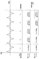
- FIG. 9B is a diagram illustrating an example of command pattern generation by the command generation unit 211a.
- FIG. 9B shows a method of generating the speed triangular wave pattern shown in the upper part of FIG. 9B or the speed trapezoidal wave pattern shown in the lower part from the movement amount X and the acceleration / deceleration time tacc.
- the speed triangular wave pattern is selected.
- the maximum value of the speed increases.
- Vmax is reached, a speed trapezoidal wave pattern is generated thereafter.
- the internal position command generated by the command generation unit 211a is also output to the servo adjustment unit 6 as monitor information.
- the command response setting function 221 is a command response index for starting the reflection of the command response index to the command response setting unit 22 from the servo adjustment unit 6 as the command response index. Input the reflection start signal.
- the command response setting function 221 performs processing such as specifying the filter processing conditions of the command response setting unit 22 based on these input information and signals.
- the command response setting function 221 includes a moving average time setting process 221a, a command response time constant setting process 221b, a secondary filter setting process 221c, and a vibration suppression filter setting process 221d.
- the moving average time setting process 221a outputs the moving average number of times by dividing the moving average time by the calculation period of the moving average filter 22a in the command response setting unit 22 when the command response index reflection start signal is on. To do.
- the attenuation ratio of the secondary filter is fixed to 1, and the frequency of the secondary filter is a value obtained by dividing the reciprocal of the time constant of the command response index by 2 ⁇ .
- the command response time constant setting process 221b sets a command response time constant of the first-order lag filter 22b having a step response characteristic of the command response time constant.
- the damping filter setting process 221d sets the depth of the damping frequency of the damping filter 22d defined by the damping frequency and the depth. All of these may not be calculated in the command response setting function 221, and may be set from a first-order lag smoothing time constant or a vibration suppression frequency / depth setting, which are manual setting parameters (not shown).
- the command response index may be a single value such as a command response cut-off frequency, a form that indicates the entire frequency characteristics such as a filter time constant or attenuation ratio of a primary delay or a secondary delay, or a rise time or delay time. There is a form that indicates transient characteristics such as an overshoot amount.
- the command response index may be set by various combinations thereof, and the filter characteristics of the command response setting unit 22 may be automatically set so that the input / output relationship of the entire command response setting unit 22 matches the command response index as much as possible.
- the stiffness setting function 231 inputs a stiffness index from the servo adjustment unit 6, and outputs a parameter set to the position / speed control unit 23 with reference to the stiffness table.
- the rigidity setting function 231 includes an automatic oscillation suppression process 231a and a rigidity table process 231b.
- the automatic oscillation suppression processing 231a normally outputs the stiffness index from the servo adjustment unit 6 as it is to the stiffness table processing 231b.
- the stiffness table processing 231b refers to the stiffness table and outputs a parameter set to the position / speed control unit 23 when the stiffness index reflection start signal from the servo adjustment unit 6 is on. In this stiffness table, the stiffness index takes 32 values from 0 to 31, and the greater the stiffness index value, the higher the disturbance suppression characteristic of the position / speed control unit 23.
- FIG. 11B shows an example of such a rigidity table.
- the stiffness table processing 231b outputs such parameter sets of position loop gain, speed loop gain, speed integration time constant, and torque filter time constant.
- the automatic oscillation suppression processing 231a When an oscillation detection signal input from an oscillation detection function 26, which will be described later, is turned on, the automatic oscillation suppression processing 231a performs rigidity with high stability until the oscillation stops instead of the stiffness index from the servo adjustment unit 6. Automatically select an indicator. Since the denominator of the disturbance suppression characteristic of the position / velocity control unit 23 is directly related to the stability of the feedback control as it is, in this example, if the stiffness index is set to a lower value, the overall gain can be lowered and the stability can be increased. . At the time of oscillation detection, the command response index may be lowered in accordance with the decrease of the stiffness index.
- the automatic oscillation suppression processing 231a outputs the current stiffness index to the servo adjustment unit 6 so that the stiffness index can be lowered on the servo adjustment unit 6 side for recovery after oscillation detection.
- the stiffness index includes an index related to the entire frequency response from disturbance torque to motor speed, and an index related to steady characteristics such as speed fluctuation rate and jitter. Like these indexes, a stiffness index generally related to disturbance suppression characteristics is input, and the parameter set of the position / speed control unit 23 is automatically set so that the input / output relationship of the position / speed control unit 23 matches the stiffness index as much as possible. Also good.
- a configuration example has been described in which a stiffness table in which an internal parameter is uniquely determined from a stiffness index is used, as in the configuration of FIG. 11A.
- a stiffness table in which an internal parameter is uniquely determined from a stiffness index is used, as in the configuration of FIG. 11A.
- the stiffness index in the development from the stiffness index to the parameter set of the position / speed control unit 23, only the relationship between one internal parameter and the stiffness index is defined, and the others are calculated from the ratio between the internal parameters. Conceivable.
- various automatic setting methods such as determining not only the rigidity index but also the setting of the load characteristic compensation unit 24 and the setting of the resonance suppression unit 25 and determining internal parameters from a calculation formula including a plurality of parameters are considered. It is done.
- the load characteristic measurement function 241 roughly includes a least square estimation process 241a that is a load characteristic measurement process itself, and other processes that automatically set the load characteristic compensation unit 24 according to the measurement result. Divided into
- the least square estimation process 241a is based on the difference between the torque command that has been pre-processed and smoothed from the torque command after filtering from the resonance suppression unit 25 and the motor position information from the encoder 4, and the motor speed, Further, the motor acceleration is calculated based on the difference.
- the least square estimation process 241a performs a least square estimation process so that the difference between the information on the actual motion and the output of the load model is minimized, and estimates an inertia estimated value, an offset load estimated value, a dynamic friction estimated value, and a viscous friction coefficient estimated. Output the value.
- the least square estimation process 241a qualitatively represents an approximate straight line that minimizes the sum of the squares of the distances from each point based on a scatter diagram of motor acceleration and torque command or motor speed and torque command.
- the estimated value is derived from the slope and intercept.
- the inertia ratio is the slope of the approximate straight line between the motor acceleration and the torque command, as shown in the upper diagram of FIG.
- the estimated value of the viscous friction coefficient is obtained from the slope of the approximate straight line between the motor speed and the torque command, as shown in the lower diagram of FIG.
- the estimated load value and the estimated dynamic friction value are obtained by calculating approximate straight lines of the motor speed and the torque command when the motor speed is positive and when the motor speed is negative, respectively.
- B average value and dynamic friction estimated value can be calculated from 1 ⁇ 2 of the difference between intercepts a, b.
- an individual estimated value reflection permission signal is given from the servo adjustment unit 6 for each estimated value. For example, when only the inertia estimated value is to be updated, only the reflection permission signal to the inertia estimated value reflecting process 241b is turned on, and the others are turned off. When it is desired to update the estimated friction value, conversely, the reflection permission to the estimated estimated value reflecting process 241c, the estimated dynamic friction value reflecting process 241d, and the estimated viscous friction coefficient reflecting value 241e corresponding to three estimated values other than the inertia estimated are permitted. Turn on the signal.
- the normal estimated value is output to the load characteristic compensator 24 as it is, but may be corrected with a certain ratio or offset value.
- the estimated value reflection permission signal is off, it is conceivable to hold the current setting of the load characteristic compensation unit 24, or to clear it to 0, or to preset it with a shipment set value or a default value.
- the adaptive filter function 251 receives the adaptive processing start signal from the servo adjustment unit 6 and sets each filter of the resonance suppression unit 25 so as to suppress the resonance vibration.
- the adaptive filter function 251 includes adaptive filter processing 251a, secondary filter setting processing 251b, and first to fourth notch filter setting processing 251c, 251d, 251e, and 251f.
- the adaptive filter processing 251a inputs motor position information from the encoder 4 when the adaptive processing start signal from the servo adjustment unit 6 is turned on. This is subjected to pre-processing such as differential processing for speed conversion and band-pass filter processing for extracting fluctuation components, and output to a variable filter and a coefficient update algorithm.
- the variable filter has the same characteristics as the notch filter of the resonance suppression unit 25, and its output is obtained by attenuating a specific frequency band.
- the frequency characteristic of the variable filter is automatically adjusted by a coefficient update algorithm corresponding to the adaptive filter mode designated by the servo adjustment unit 6 so that the difference between this and the normative input becomes zero.
- the third notch filter setting process 251e and the fourth notch filter setting process 251f apply the frequency characteristics of the variable filter to the frequencies, widths, and depths of the third notch filter and the fourth notch filter, respectively. Furthermore, the adaptive filter mode specified by the servo adjustment unit 6 can also specify the timing and conversion method of the third notch filter setting process 251e and the fourth notch filter setting process 251f.
- the two notch filters are automatically adjusted, but the first notch filter setting process 251c and the second notch filter setting process 251d may be controlled to automatically adjust all four.
- the characteristics of the secondary filter can also be automatically adjusted by changing the frequency characteristics of the variable filter and controlling the secondary filter setting processing 251b.
- three filter characteristics that are not automatically adjusted can be changed with manually set parameters (not shown).
- the adaptive filter processing 251a outputs an adaptive result such as the frequency, width, and depth of the variable filter to the servo adjustment unit 6.
- an adaptive result such as the frequency, width, and depth of the variable filter
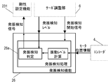
- the oscillation detection function 26 detects the oscillation by inputting the motor position information from the encoder 4 to the oscillation detection processing 26a when the oscillation detection start signal from the servo adjustment unit 6 is turned on. The process to start is started.
- the oscillation detection function 26 extracts the motor fluctuation, calculates the vibration level in the same manner as the adaptive filter, and detects the oscillation state of the motor 3 and the load 5 based on the comparison with the oscillation detection level designated by the servo adjustment unit 6.
- an oscillation detection signal is turned on and transmitted to the stiffness setting function 231 described above, and a stiffness index in a direction in which oscillation is suppressed is selected.
- the oscillation detection may use any information as long as it is an index related to vibration. For example, even if oscillation is detected by torque command, position command, disturbance torque estimated value, load position information, sound information by a microphone, acceleration information of the motor 3 or load 5 by an acceleration sensor, torque / pressure information by a load cell, etc. Good.
- the evaluation index measurement function 27 inputs the motor position information from the encoder 4, the post-selection position command from the command selection unit 21, and the post-filter torque command from the resonance suppression unit 25. Then, the evaluation index measurement function 27 inputs the measurement thresholds such as the positioning completion range, the maximum torque limit, and the vibration detection level from the servo adjustment unit 6 and responds to the control signals such as the measurement start signal, the number of measurements, and the maximum stop time. Then, various evaluation indexes are output to the servo adjustment unit 6.
- evaluation index itself and its calculation method are various, for example, a list of example items that become evaluation indices such as positioning settling time is given in FIG. As shown in FIG. 15, the evaluation indices include positioning settling time and command time. Further, a method for calculating these evaluation indexes will be described below with reference to FIG.
- the deviation (position deviation) between the position command after selection and the motor position information from the encoder 4 is calculated from the servo adjustment unit 6. It can be measured in the time until it is within the positioning complete range.
- the command time can be defined as the time during which the position command after selection from the command selection unit 21 is changing, and the tact can be defined as the period after the position command after selection changes first and then stops. . Further, the tact may be limited to the elapse of the maximum stop time from the servo adjustment unit 6 after the post-selection position command is stopped.
- the overshoot amount can be defined as the maximum / minimum position deviation between tacts in the direction opposite to the direction of the position command after selection.
- the positioning completion output signal turns on when the position deviation enters the positioning completion range and turns off when the position deviation is out of the range, but the number of changes in the INP signal between tacts can be used as an index for positioning settling. The number of INP changes may be limited after the position command is stopped.
- the command speed and the motor speed can be calculated from the difference between the position command after selection from the command selection unit 21 and the motor position information from the encoder 4.
- the torque command is the post-filter torque command from the resonance suppression unit 25, and the position deviation is the deviation between the post-selection position command and the motor position information from the encoder 4. If the maximum and minimum values between these tacts are used as evaluation indexes, a considerable part of the inter-tact movement can be grasped. With respect to the torque command, an effective value is obtained from the square root square between the tacts, and this is a very useful evaluation index for selecting the capacity of the motor and the motor driving device.
- the index relating to the torque can be used for determining the maximum acceleration pattern in step 2 by comparison with the maximum torque limit from the servo adjustment unit 6.
- evaluation index measurement function 27 it is an important aspect of the evaluation index measurement function 27 to compress the data of a large amount of motor control information that can be acquired in real time into a small number of evaluation indexes that are more meaningful by using a certain algorithm.
- FIG. 1 shows a flowchart of the servo adjustment steps of the present embodiment for the basic function for driving and controlling the motor shown in FIG. 2 and the automatic adjustment function described above.
- this embodiment it is assumed that the following servo adjustment steps are implemented in the servo adjustment unit 6 of FIG.
- the servo adjustment step according to the present embodiment includes one of the following five steps.
- Step 1 is an initial setting and is executed before Step 2 to Step 5.
- information related to the controlled object is input, and initial conditions and valid / invalid selection of functions for the adjustment steps after step 2 are selected.
- Step 2 measures load characteristics. Step 2 is executed before Step 3 to Step 5, and after setting various functions, the test run function is operated in an operation pattern in which the least square estimation of load characteristic measurement works appropriately, and an optimum estimation result is obtained. In addition, an operation pattern of the trial operation function is given to the adjustment steps after step 3.
- Step 3 is a step for adjusting the stiffness setting function, and is executed before Step 4 and Step 5.
- Step 3 increases the stiffness index while utilizing the adaptive filter function, and searches for the maximum stiffness that is the upper limit of the stiffness index.
- index change after step 4 is provided.
- Step 4 is a step for measuring the command response. Step 4 is executed before step 5, and based on the maximum stiffness of step 3, a search pattern is generated by combining the stiffness index and the command response index, and the evaluation index is measured and stored by the evaluation index measurement function.
- Step 5 is executed last, and a combination of the stiffness index and the command response index is extracted from the evaluation index of Step 4 according to some recommended conditions representing the characteristics required by the user and presented. Further, after the selection, after fine adjustment and trial operation are repeated, there is a step of storing the final adjustment result in the motor drive device.
- the load characteristic measurement function is first operated in step 2 through step 2 to step 4, and the load characteristic compensation unit is set based on the measurement result.
- the necessary test operation pattern is automatically determined in the measurement after step 2 in a state where the influence of the load that varies greatly depending on the use conditions is suppressed.
- step 3 initial setting necessary for determining the maximum value of the stiffness index is performed, and a trial operation operation linked with step 2 is performed. Thereby, the determination of the stiffness index maximum value and the setting of the resonance suppression unit corresponding to the stiffness index can be stored.
- step 4 a search pattern combining a plurality of stiffness indicators and a plurality of command response indicators is determined from the maximum stiffness specified in step 3, and the evaluation indicators are measured for all combinations of search patterns.
- This is a configuration to memorize.
- servo adjustment is performed in the order from step 2 to step 4
- adjustment can be performed as a flow in which each step is linked. Thus, even an operator who does not have detailed knowledge of servo adjustment can perform each step. An appropriate adjustment result can be obtained simply by executing the above in order.
- step 2 to step 4 during the period in which the test operation is valid, the oscillation detection function 26 is enabled, and the rigidity index is lowered for the oscillation detection due to an unexpected situation, and the servo adjustment can be continued.
- the evaluation index measurement function 27 has a function of measuring and recording evaluation indexes for all operations.
- the adjustment result by the same servo adjustment step can be indicated by the same evaluation index. For this reason, servo adjustment with strong personality is eliminated, and even an operator having no knowledge of servo adjustment can obtain a highly accurate adjustment result.
- the measurement record of the evaluation index can also be used for analysis when an abnormality occurs in the servo adjustment step. Furthermore, it is also effective to record the evaluation index periodically and use it for analysis such as secular change and life prediction from the change of the index.
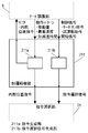
- the motor drive device includes the command selection unit 21, the command response setting unit 22, the position / speed control unit 23, the load characteristic compensation unit 24, and the resonance suppression unit 25. It has one of the basic functions of motor control. Further, the motor driving apparatus includes a test run function 211, a command response setting function 221, a rigidity setting function 231, a load characteristic measurement function 241, an adaptive filter function 251, an oscillation detection function 26, and an evaluation index measurement function 27. One of the seven automatic adjustment functions.
- the servo adjustment method includes step 1 for initial setting, step 2 for performing load characteristic measurement and command pattern determination, a stiffness index maximum value, and a resonance suppression unit corresponding to the stiffness index. Step 3 for storing the setting, step 4 for storing the evaluation index for the designated operation by combining the stiffness index and the command response index, and step 5 for obtaining the final adjustment result from the evaluation index according to the search condition One of them.
- the first embodiment is configured as described above, an operator who does not have detailed knowledge of servo adjustment at each step of servo adjustment can perform appropriate adjustment by simply executing the five steps in order. The result can be obtained.
- FIG. 16 is a diagram showing an operation screen of the servo adjustment step 1 in the second embodiment.
- Adjustment guideline selection includes information on search methods, control objectives, whether there are load fluctuations, whether the target device emphasizes responsiveness or stability, and what mechanism the target device has.
- a combo box is available for selection. As measurement conditions, the positioning completion width, oscillation detection level, and maximum torque limit can be entered numerically in the edit box.
- Step 2 After completing a series of initial settings, you can proceed to Step 2 by pressing the “Next” button at the bottom right.
- the current step is displayed at the top, and the progress of the servo adjustment step can be confirmed.
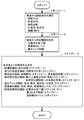
- FIG. 17 is a flowchart showing the procedure of step 1 of servo adjustment in the present embodiment.
- Step 1-1 is executed before Step 1-3, and various adjustment pointers are selected using the adjustment pointer setting block on the operation screen. Examples of combo box items are given in the decision table below.
- Another adjustment guideline may be generated internally from a plurality of adjustment guidelines.
- Step 1-2 is executed before Step 1-3, and various measurement threshold values are set using the measurement condition setting block on the operation screen. Between the measurement condition on the screen and the measurement threshold, scaling such as constant unit conversion and sign inversion, and offset processing such as addition of a predetermined value may be performed. Step 1-1 and step 1-2 may be set in any order together with the operation screen.
- Step 1-3 determines the initial conditions required in the following steps based on the settings from the operation screen.
- the initial conditions set here include the following items. That is, the number of trial operation functions used in steps 2 to 4, the initial command response of the command response setting function used in step 2 and the initial rigidity of the rigidity setting function, and the minimum load characteristic measurement function used in step 2 There are validity / invalidity of the square estimation function, and whether or not the load characteristic measurement result used in step 4 is reflected in the load characteristic compensator. Also, the adaptive filter function used in step 3 is enabled / disabled, the operation mode is set, the oscillation detection function used in steps 2 to 5 is enabled / disabled, and the oscillation detection level is used. The positioning completion range and maximum torque limit of the evaluation index measurement function to be used are set. These are set based on the initial condition determination table described later at the timing of pressing the “Next” button, which indicates the transition to Step 2 as the next step.
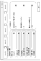
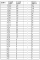
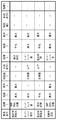
- FIG. 18 shows an initial condition determination table in step 1-3 in the second embodiment.
- the search method has two items, high speed search and full search.
- high speed search is selected, the number of trials of the trial operation function 211 is smaller than in the case of full search, and higher speed search is possible.
- PTP control there are two items for control purposes: PTP control and CP control.
- PTP control since the positioning settling time is generally a target, the measurement threshold value is set as it is in the positioning completion range of the evaluation index measurement function 27.
- CP control since an index for positioning settling time is not required, the positioning completion range may be a fixed value.
- responsiveness and stability items There are three responsiveness and stability items: emphasis on responsiveness, balance, and stability. These determine the validity / invalidity of the adaptive filter function 251 and the maximum torque limit of the evaluation index measurement function 27.
- the resonance suppression unit 25 is appropriately set by the adaptive filter function 251
- the maximum stiffness that is the maximum value of the stiffness index can be increased, and the disturbance suppression characteristics are improved.
- the stability is lowered in the sense of robustness, they are in a trade-off relationship.
- the motor is often operated with an operation pattern that is close to the characteristics of the motor. Therefore, if the operation pattern in the gain adjustment step is also set to high acceleration / deceleration, matching with the result in actual operation is improved.
- the validity / invalidity of the adaptive filter is specified by adjustment guidelines for both load fluctuation and responsiveness / stability. If these contradict, the rule is determined so that the invalid side is given priority, for example.
- the initial command response index of the command response setting function 221 determines the initial command response index of the command response setting function 221 and the initial stiffness index of the stiffness setting function 231.
- the measurement time can be shortened by initializing a higher command response index or rigidity index.
- the lower the rigidity assumed from the mechanism the lower the command response index and the rigidity index are initialized, thereby avoiding oscillation detection in the trial operation in step 2.
- the oscillation detection in the rigidity measurement in step 3 can be reduced by changing the maximum rigidity limit by the mechanism.
- the operation mode setting of the adaptive filter function 251 is changed according to the mechanism (rigidity), thereby stabilizing the operation of the adaptive filter function 251 based on prior information. That is, for example, the high rigidity mode has a narrow notch width and a deep notch depth for high rigidity, the low rigidity mode has a wide notch width and a shallow notch depth for low rigidity, and has intermediate characteristics between the two for medium rigidity.
- the operation of the adaptive filter function 251 is stabilized by, for example, selecting the medium rigidity mode.
- the oscillation detection level of the oscillation detection function 26 is determined according to the mechanism (rigidity).
- Oscillation detection accuracy can be improved by multiplying the setting under measurement conditions by a multiplier according to the mechanism (rigidity) or by setting a measurement threshold value held in a table.
- the vibration detection level used in step 3 is one that ends the stiffness search before detecting the normal oscillation, and is set to a value lower than the oscillation detection level. In this example, calculation is performed by multiplying a constant less than 1 by the oscillation detection level.
- Step 1-1 Step 1-1
- Step 1-2 Step 1-3
- Step 1-3 the order of Step 1-1, Step 1-2, and Step 1-3 may be changed unless the order is specified.
- step 1-1 or step 1-2 may be performed first.
- step 1 of the servo adjustment method of the present embodiment includes the number of trial operation function trials, the initial command response index of the command response setting function, the initial stiffness index and maximum stiffness limit of the stiffness setting function, and the load characteristic measurement function.
- step 1 of the present embodiment includes a search method, a control purpose, a load variation, an index of responsiveness / stability, a qualitative adjustment guideline such as a mechanism and rigidity of a load to be controlled, a positioning completion range,
- a quantitative measurement threshold such as an oscillation detection level and a maximum torque limit is input, and the initial condition is output from a combination thereof.
- the initial setting and valid / invalid of each automatic adjustment function used for servo adjustment can be performed with condition settings easy to understand for the user.
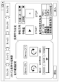
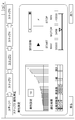
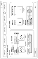
- FIG. 19 is a diagram showing an operation screen in step 2 of servo adjustment in the third embodiment.
- the left half is an operation range setting block for setting an operation range by the trial operation function.
- the right half is a load characteristic measurement block for measuring load characteristics. It has a combo box for setting the moving direction / moving amount, and a START / STOP button for starting / stopping measurement of load characteristics.
- the load characteristic measurement results are in the form of inertia ratio, unbalanced load, dynamic friction, viscous friction coefficient, etc., and displayed in a list as shown in the lower right of the figure, the load characteristic measurement results can be seen and useful in real time.
- Step 3 When the load characteristic measurement is completed and satisfied with the measurement result, you can proceed to Step 3 by pressing the “Next” button at the bottom right. If the result is unsatisfactory at this point, the measurement result can be discarded and the process can be returned to step 1 by pressing the start button again to measure again or by pressing the “return” button at the lower left.
- FIG. 20 is a flowchart showing the procedure of step 2 of servo adjustment in the present embodiment.
- Step 2-1 is executed before the trial operation of Step 2-4, and the initial command response index set in Step 1 is set in the command response setting function 221 and the initial stiffness index is set in the stiffness setting function 231.
- Initialize indicator and command response indicator This step has the effect of shortening the measurement time and avoiding oscillation during the test run.
- Step 2-2 is executed before the trial operation of Step 2-4, and in order to invalidate the adaptive filter function 251, the adaptive processing start signal is turned off, and all the notch filters of the resonance suppression unit are invalidated (the input signal is To the setting of “through”.
- This step ensures that the load characteristic measurement is performed with a low stiffness index that can be driven without a notch filter. For this reason, the effect of making the load characteristic measurement result less susceptible to the resonance characteristic of the motor 3 and the load 5 and the adaptation result of the adaptive filter function 251 can be obtained.
- Step 2-3 is executed before the trial operation of Step 2-4, sets the oscillation detection level set in Step 1 to the oscillation detection function 26, and turns on the oscillation detection start signal to enable the oscillation detection processing.
- the stiffness setting is automatically lowered by the oscillation automatic suppression processing in cooperation with the stiffness setting function 231, and the servo adjustment step can be continued.
- the stiffness setting is lowered, it is also effective to automatically lower the initial stiffness setting on the servo adjustment unit 6 side and smoothly perform the recovery after the oscillation is stopped.
- Step 2-4 is executed before the trial run operation of Step 2-7, and the motor energization is started through the control signal to the trial run function 211 with the Servo ON / Servo OFF button in the operation range setting block on the operation screen.
- the range that can be operated by servo adjustment is set by actually moving the motor with the operation button. After the operation range is set, if the motor is moved to the operation start position, a movement direction and a movement amount that can operate within the operation range are selected.
- This operable range setting is preferably set as wide as possible because it is effective even when command reselection is performed in step 4. Further, if the operation range is sufficiently wide, the trial operation may be repeatedly started while changing the operation start position with the same movement amount and the same movement direction.
- Step 2-5 is executed before the trial operation of Step 2-7, and at the timing when the START button is pressed, the load characteristic measurement start signal is turned on in order to validate the load characteristic measurement function 241. If there is a reason to invalidate the load characteristic measurement in step 1, such as when the load fluctuation of the adjustment policy is selected as steep, the load characteristic measurement start signal may remain off. In that case, step 2 is performed only to set the maximum acceleration pattern.
- Step 2-6 is executed before the trial run operation in Step 2-7, and the test run operation pattern that satisfies the minimum acceleration among the constraint conditions (speed, acceleration, operation time, etc.) under which the load characteristic measurement function 241 can operate at the minimum is set.
- the test run function 211 is initialized. An example of setting the operation pattern of the test run function 211 from the operation acceleration and the movement amount in Step 2-6 and Step 2-7 will be described in detail with reference to FIGS. 21A and 21B.
- Step 2-7 a trial operation start signal is sent to the trial operation function 211 for the number of trials set in Step 1 with the current operation pattern (travel amount, maximum speed, acceleration / deceleration time), and the trial operation for the number of trials is performed. Do. If the load characteristic measurement function 241 is enabled in step 2-5, the load characteristic measurement result can be obtained by this operation. Since load characteristic measurement results can be obtained for each acceleration setting, all of these may be stored.
- step 2-8 every time the trial run operation in step 2-7 is completed, the evaluation index measurement by the evaluation index measurement function 27 is performed.
- the maximum torque in Step 2-10 it is necessary to measure at least one evaluation index related to the torque command such as the torque command maximum / minimum value and the torque command effective value.
- step 2-9 it is confirmed whether or not the oscillation detection function 26 started in step 2-3 has detected oscillation during the trial run operation in step 2-7.
- an oscillation detection signal is sent to the stiffness setting function 231. Therefore, the operation of lowering the stiffness index in step 2-9-1 is automatically performed, and the oscillation state is avoided.
- the process proceeds to step 2-6, and the measurement is performed again from the minimum acceleration of the load characteristic measurement with a lower and more stable initial stiffness index.
- Step 2-10 determines whether the evaluation index related to the measured torque command exceeds the maximum torque limit specified in Step 1 as a result of Step 2-8.
- the load characteristic measurement function 241 can obtain a more accurate result as the motion acceleration is higher. Therefore, if the maximum torque limit is not reached in step 2-10, the acceleration of the trial operation is increased in step 2-10-1, and the operation pattern of the trial operation function 211 is reset. Perform the test run again. Thereby, an accurate load characteristic measurement result can be obtained with a plurality of acceleration settings.
- step 2-11 when the index related to the torque command exceeds the maximum torque limit in step 2-10, the current movement amount, maximum speed, and acceleration / deceleration time are set to the maximum acceleration of the trial operation function 211 used in step 3 and subsequent steps. Store as a pattern. Accordingly, an operation pattern that can be driven within the maximum torque limit can be obtained according to the load characteristics of the load 5.
- step 2-12 if the index related to the torque command exceeds the maximum torque limit in step 2-10, the reflection of the estimated value is permitted according to whether the load characteristic measurement result specified in step 1 is reflected in the load characteristic compensator.
- the load characteristic compensator 24 By manipulating the signal, part or all of the load characteristic measurement result is set in the load characteristic compensator 24. Since the estimated inertia value greatly affects the stability of the control system, it is better to set it to the result measured last in step 2.
- the offset load estimated value, dynamic friction estimated value, and viscous friction estimated value are also affected by the command pattern and command response measurement conditions, and are reset in step 4. Therefore, this setting is not essential.
- step 2-13 after step 2-12 is completed, if the load characteristic measurement function 241 is valid in step 2-5, the load characteristic measurement start signal is turned off and invalidated. Under the condition that the command response index and the rigidity index in step 3 are high, vibration due to resonance characteristics may occur. Further, in the command reselection in step 4, there is a possibility that an operation pattern that is not suitable for load characteristic measurement may be selected. In any case, the load characteristic measurement result is not stable and the accuracy tends to deteriorate. For this reason, it is important to disable the load characteristic measurement function 241 in step 2-13.
- step 2 may be changed unless the order is specified.
- step 2-1 to step 2-3 may be performed first as long as the test run operation is not started. There is no problem even if the order of Step 2-11 and Step 2-12 is changed.
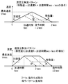
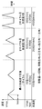
- 21A and 21B are operation pattern diagrams in step 2 of servo adjustment in the present embodiment.
- the minimum acceleration required for the measurement of the load characteristic measurement function 241 is 1000 [r / min / s]
- the movement amount is two rotations
- the movement direction is a positive / negative reciprocation pattern as shown in FIG. 21A.
- the movement amount is four rotations, and two examples of the unidirectional movement pattern in the positive direction ⁇ the positive direction are given.
- acceleration 4000 [r / min / s], acceleration / deceleration time 0.173 [s], and maximum speed 693 [r / min].
- the acceleration / deceleration time decreases instead of increasing the maximum speed. If the maximum speed exceeds the maximum measurement allowable by the motor 3 or the load 5, the measurement may be terminated. Also, when the operation time required for the measurement by the load characteristic measurement function 241 cannot be secured, it is better to end the measurement in the same manner.
- step 2 of the servo adjustment method of the present embodiment the load characteristic measurement function is operated according to the valid / invalid setting of the load characteristic measurement function specified in step 1, and the test operation function is performed within the set operation range.
- the motor is operated for the number of trials specified in step 1.
- this step 2 is a structure which sets a load characteristic compensation part from the load characteristic measurement result measured while changing operation
- this step 2 includes a configuration in which the initial stiffness index specified in step 1 is set in the stiffness setting function and the initial command response index is set in the command response setting function before the trial operation function is validated.
- this step 2 includes a configuration in which the adaptive filter function and the notch filter of the resonance suppression unit are disabled unconditionally before the test operation function is enabled.
- the oscillation detection function is validated at the oscillation detection level specified in step 1 before the trial operation function is validated, and if oscillation is detected during the trial operation, this is notified to the stiffness setting function.
- This step 2 includes a configuration in which the load characteristic is measured again from the beginning after the stiffness index is lowered to suppress oscillation.
- this step 2 the test operation is started from the minimum acceleration to which the load characteristic measurement function can be applied, and the evaluation index is measured while increasing the acceleration.
- this step 2 includes the structure which sets the load characteristic measurement result at the time of the evaluation parameter
- this step 2 starts the test operation from the minimum acceleration to which the load characteristic measurement function can be applied, and measures the evaluation index while increasing the acceleration.
- This step 2 includes a configuration in which the highest acceleration pattern at the time when the evaluation index related to the torque command reaches the maximum torque limit specified in step 1 is used as the operation pattern of the trial operation function in step 3.
- the initial setting necessary for the load characteristic measurement is performed in cooperation with step 1, and the maximum acceleration pattern of the test operation function necessary in the subsequent steps is automatically set. And accurate load characteristic measurement results can be obtained.
- FIG. 22 is a diagram showing an operation screen of the servo adjustment step 3 in the fourth embodiment.
- this screen has only a stiffness measurement block, and those that can be operated from the screen include a start / pause (START) button, an emergency stop (STOP) button, and a step for searching for the maximum stiffness. Only the number of trials for each stiffness index in FIG. Other than that, the servo adjustment unit 6 displays the current stiffness indicator displayed by the stiffness setting function 231 and its bar graph representation, the adaptation result of the adaptive filter function 251, and the current internal command position returned by the test operation function 211 with respect to the operation range. It does not affect the motor operation.
- STOP start / pause
- STOP emergency stop
- Step 4 When the rigidity measurement is completed and satisfied with the measurement result, you can proceed to Step 4 by pressing the “Next” button at the bottom right. If the result is unsatisfactory at this time, the measurement can be discarded by returning to step 2 by pressing the start button again or by pressing the “return” button at the lower left.
- FIG. 23 is a flowchart showing the procedure of step 3 of servo adjustment in the present embodiment.
- Step 3-1 sets the adaptive filter mode from the servo adjustment unit 6 when the adaptive filter function 251 is enabled by the designation in Step 1 before starting the search for the maximum rigidity in Step 3-2.
- the adaptive processing start signal is turned on.
- enabling the adaptive filter function 251 can increase the maximum rigidity and increase the possibility of obtaining a better adjustment result.
- the adaptive filter function 251 is used while being disabled, so that the influence due to the fluctuation of the resonance characteristics can be minimized.
- Step 3-2 is the current stiffness index, and the trial run operation with the maximum acceleration pattern determined in Step 2 is performed for the number of trials specified in Step 1.
- the adaptive filter function 251 is enabled in step 3-1, the adaptive filter processing works, and the notch filter setting of the resonance suppression unit 25 may be changed during operation according to the adaptive filter mode. In that case, since the evaluation index related to vibration in step 3-3 may change, the trial run operation in step 3-2 may be performed again from the beginning.
- step 3-3 every time the test operation in step 3-2 is completed, the evaluation index measurement function 27 measures the evaluation index related to vibration.
- the evaluation index measurement function 27 measures the evaluation index related to vibration.
- the vibration level described in the evaluation index measurement function 27 in FIG. 15 can be used for this purpose.
- the number of INP changes can be used as an evaluation index related to vibration.
- step 3-4 it is confirmed whether the oscillation detection function 26 activated after step 2 is not detecting oscillation during the trial run operation in step 3-2.
- an oscillation detection signal is sent to the stiffness setting function 231. Therefore, the operation of lowering the stiffness index is automatically performed, and the oscillation state is avoided.
- the process immediately proceeds to step 3-4-1, and the search is terminated with the low rigidity index taking a certain margin as the maximum rigidity from the rigidity index at the time of oscillation detection, and the process proceeds to step 3-8.
- step 3-5 as a result of step 3-3, it is determined whether or not the evaluation index relating to the measured vibration exceeds the vibration detection level designated in step 1.
- the oscillation detection function 26 works when a considerably large vibration is usually generated. Therefore, the servo adjustment can be continued with more peace of mind by stopping the rigidity search at a vibration level lower than this. Therefore, if the evaluation index related to vibration exceeds the vibration detection level in step 3-5, the process immediately proceeds to step 3-5-1, and the search is ended with the value immediately before the current stiffness index as the maximum stiffness, Move on to step 3-8.
- step 3-6 when the test run operation in step 3-2 is completed without detecting the oscillation in step 3-3 and the vibration detection in step 3-4, the current stiffness is set to the maximum stiffness limit specified in step 1. Determine if the indicator is reached.
- This maximum stiffness limit value depends only on the mechanism (rigidity) of the adjustment policy in the second embodiment, but the capacity of the motor 3 being used, the capacity of the motor driving device 2, and the previous step 2 It may be based on the measurement result of the load characteristic measurement function 241 or the adaptation result of the adaptive filter function 251.
- step 3-6 If the maximum stiffness limit is not reached in step 3-6, the current setting of the resonance suppression unit 25 is stored in a storage area (not shown) in association with the current stiffness index in step 3-6-1. If the adaptive filter function 251 is activated in step 3-1, the setting of the resonance suppression unit 25 may be different for each stiffness. This recording is utilized in step 4 described later.
- Step 3-6-2 is executed after Step 3-6-1, a one-step rigidity index is set in the rigidity setting function 231, and the trial operation is executed again in Step 3-2.
- the loop from step 3-2 to step 3-6 ends with the determination of any one of steps 3-4 to 3-6 at a finite number of times.
- Step 3-7 is executed when the maximum rigidity limit is reached in Step 3-6, the current rigidity index, that is, the maximum rigidity limit is set to the maximum rigidity, the search is terminated, and the process proceeds to Step 3-8.
- Step 3-8 is executed at the end of Step 3, and when the adaptive filter function 251 is enabled in Step 3-1, the adaptive adjustment start signal is turned off by the servo adjustment unit 6 to turn off the adaptive filter.
- the function 251 is invalidated.
- the setting of the resonance suppression unit 25 at this time is usually the last adaptation result. However, if the stiffness index is different from the maximum stiffness, such as when oscillation is detected at step 3-4, when vibration is detected at step 3-5, or when the stiffness index is lowered in preparation for execution of step 4, The resonance suppression unit 25 needs to be set in the resonance suppression unit setting corresponding to the stiffness index stored in Step 3-6-1.
- step 3 may be changed unless the order is specified.
- step 3-4 and step 3-5 can be interchanged.
- 24A, 24B, and 24C are operation pattern diagrams in step 3 of servo adjustment in the present embodiment.
- case 1 in FIG. 24A and when oscillation is detected in step 3-4 case 2 in FIG. 24B and when the vibration detection level is exceeded in step 3-5 are shown. It is shown in the operation pattern diagram as case 3 of 24C.
- the trial run operation of the maximum acceleration pattern determined in step 2 starts in step 3-2 from the stiffness index 11 in step 2. Since the oscillation detection in step 3-4 and the vibration detection level excess in step 3-5 are not detected every two trials, the stiffness indicator in step 3-6-2 is reached until the maximum stiffness limit is reached in step 3-6. Go up one by one. During this time, the adaptive filter function 251 is enabled, and the settings of the third notch filter and the fourth notch filter of the resonance suppression unit 25 change each time the stiffness index increases. The setting of the resonance suppression unit 25 is stored as a set with the current stiffness index in step 3-6-1. When the trial run operation for the number of trials is completed with the maximum stiffness limit 15, the determination in step 3-6 becomes YES, the maximum stiffness is set to 15 in step 3-7, and step 3 ends.
- the change in the resonance suppression unit 25 setting of the case 1 is not described, but it is assumed that the same operation is performed.
- the oscillation detection function 26 detects oscillation and the oscillation detection signal is turned on in step 3-4 when the second operation is started with the stiffness indicator 14. is doing.
- the stiffness index is lowered to 8 to indicate that the oscillation is stopped.
- the routine proceeds to step 3-4-1, where the maximum stiffness is set to the stiffness 12 taking a two-step margin from the stiffness index 14 at the time of oscillation detection, and step 3 is completed.
- a setting for the resonance suppression unit 25 corresponding to the stiffness 12 at the same time a frequency of 1200 Hz, a width of 2, and a depth of 0 may be set for the third notch filter.
- the change in the setting of the resonance suppression unit 25 is recorded.
- the evaluation index related to vibration is measured by the evaluation index measurement function 27, and when the trial operation of the rigidity index 14 before reaching the maximum rigidity limit is completed in step 3-6, the vibration of step 3-5 is completed. Since the index related to exceeds the vibration detection level, the maximum rigidity is set to the immediately preceding rigidity index 13 in Step 3-5-1, and Step 3 is completed.
- the resonance suppression unit 25 corresponding to the stiffness index 13 may be set at the same time.
- step 3 of the servo adjustment method of the present embodiment the trial run operation of the number of trials specified in step 1 is performed with the maximum acceleration pattern of step 2.
- step 3 the stiffness index is increased until the maximum stiffness limit specified in step 1 is reached.
- the stiffness index reaches the maximum stiffness limit specified in step 1, the maximum stiffness is determined based on this. It is a configuration.
- this step 3 includes a configuration in which the adaptive filter function specified in step 1 is set to be valid / invalid before starting the test operation, and the adaptive filter function is invalidated after the maximum stiffness is determined.
- this step 3 includes a configuration in which the set value of the resonance suppression unit immediately before raising the stiffness index is stored in association with the current stiffness setting.
- this step 3 includes a configuration in which, when oscillation is detected during the test operation, the maximum stiffness is determined based on the stiffness index at the time of oscillation detection.
- this step 3 includes a configuration in which, when the evaluation index related to vibration exceeds the vibration detection level specified in step 1 during the test operation, the maximum rigidity is determined based on the immediately preceding rigidity index.
- step 3 of the servo adjustment the initial setting necessary for determining the maximum stiffness is performed in cooperation with step 1, the test operation operation in cooperation with step 2 is performed, and the maximum stiffness is determined. And the setting of the resonance suppression part corresponding to a rigidity parameter
- FIG. 25 is a diagram showing an operation screen of servo adjustment step 4 in the fifth embodiment.
- the left half is a command selection block, and includes radio buttons for selecting an operation in accordance with the internal position command by the same trial operation function 211 as in Step 3 and an operation in accordance with the external position command.
- the trial operation function 211 is invalidated and the command selection signal to the command selection unit 21 is switched to the external position command side. If the internal position command is selected, the current test operation function is continued.
- the setting of the maximum acceleration pattern determined in step 2 is displayed in the screen movement amount, maximum speed, and acceleration / deceleration time.
- the test run setting is set according to the operation pattern required by the user for the device. It is possible to change.
- the motor can be moved with the positive / negative direction moving button.
- the right half is a command response measurement block that controls command response measurement with the selected position command.
- the command response measurement is started by pressing the measurement / pause button (START).
- the positioning index, the overshoot amount, the vibration level, and the number of INP changes are displayed on the screen in real time.
- Step 5 When the command response measurement is complete and the measurement result is satisfied, you can proceed to Step 5 by pressing the “Next” button at the bottom right. If the result is not satisfactory at this point, the measurement can be discarded by pressing the start button again or by pressing the “return” button at the lower left to return to step 3.
- FIG. 26 is a flowchart showing the procedure of step 4 of servo adjustment in the present embodiment.
- step 4-1 before starting the command response measurement in step 4-4, a search pattern combining a plurality of stiffness indicators and command response indicators is determined based on the maximum stiffness specified in step 3. This search pattern will be described in detail with reference to FIGS. 27A, 27B, and 27C.
- step 4-2 before the command response measurement is started in step 4-4, the load characteristic measurement function is set in step 2 according to whether or not the load characteristic measurement result set in step 1 is reflected in the load characteristic compensator 24.
- the estimated load characteristic value measured at 241 is applied to the load characteristic compensation unit 24.
- the result estimated by the maximum acceleration pattern in step 2 may be applied, or the calculation result is calculated from the average or maximum / minimum value of the measurement result, or depending on the operation pattern selected in step 4 You may decide.
- step 4-3 before starting the command response measurement in step 4-4, the command selection block on the operation screen is operated to reselect the command.
- step 4-4 command response measurement is started by pressing the measurement / pause button (START) in the command response measurement block on the operation screen.
- STT measurement / pause button
- step 4-5 before actually performing the operation in step 4-7, the combination of the stiffness index and the command response index is changed according to the search pattern determined in step 4-1. Then, the command response setting function 221 sets the command response setting unit 22 according to the command response index, and the stiffness setting function 231 sets the position / speed control unit 23 according to the stiffness index.
- step 4-6 before actually performing the operation in step 4-7, the resonance suppression unit 25 stored in step 3 corresponding to the stiffness index set in step 4-5 is reflected. Note that it is desirable to change the stiffness index setting in step 4-5 and the resonance suppression unit 25 setting in this step as simultaneously as possible.
- this flowchart is divided into different steps, the reflection timing for actual control may be aligned with a synchronization function (not shown) on the motor drive device 2 side.
- step 4-7 the motor is operated for the number of trials according to the command selected in step 4-3.
- step 4-8 the evaluation index in each operation is measured by the evaluation index measurement function 27 from the motor operation in step 4-7.
- the evaluation index here is settling time related to positioning accuracy, overshoot amount, number of INP changes, vibration level, and the like. If the storage capacity is not limited, as many evaluation indexes as possible should be collected.
- the measurement result is stored in a storage area (not shown) in association with the search pattern.
- step 4-9 it is determined whether all searches by all search patterns have been completed. If the full search has not been completed yet, the process returns to step 4-5 to change the combination of the stiffness index / command response index again. When the full search is completed, step 4 is ended.
- steps 4-1 to 4-3 may be performed in any order before the command response measurement is started in step 4-4.
- FIG. 27A is a diagram showing a search pattern table in step 4-1 in the present embodiment.
- step 4-1 the command response index No. 1 to No. Choose 6.
- the rigidity index six kinds are selected from the maximum rigidity to the five-level lower rigidity index including the maximum rigidity.
- the command response measurement is performed while changing 36 patterns in combination as a search pattern in order in step 4-5. Naturally, the number of combinations of search patterns may be increased or decreased as necessary depending on the balance between measurement accuracy and measurement time.
- This combination is arranged so as to be arranged in a grid when the rigidity index is taken on the vertical axis and the command response index is taken on the horizontal axis as shown in FIGS. 27B and 27C.
- the combination of the stiffness index and the command response index is not limited to this example, and the corresponding command response index No. is referred to by referring to the search pattern table for each stiffness. 1 to No. 6 can also be selected. In this case, the grid is distorted into a parallelogram.
- 28A, 28B, and 28C are operation diagrams at the time of command response measurement in the present embodiment.
- step 4-5 the stiffness index is set to 10 which is the lowest value (5 steps below the maximum stiffness 15), and the command response index is set. No. 1 of 22 is selected.
- step 4-6 the resonance suppression unit 25 setting corresponding to the stiffness index 10 is simultaneously reflected. (In this example, both the third notch and the fourth notch are invalid).
- step 4 of the servo adjustment method of the present embodiment a search pattern combining a plurality of stiffness indicators and a plurality of command response indicators is determined from the maximum stiffness specified in step 3. Furthermore, this step 4 uses the command response setting function and the stiffness setting function to change the command response index and the stiffness index in order, and the trial run function of the number of trials set by step 1 with the maximum acceleration pattern of step 2 Make it work. And this step 4 is the structure which measures and memorize
- this step 4 includes a configuration for reflecting the resonance suppression unit setting for each stiffness index stored in step 3 to the resonance suppression unit when the stiffness index is changed.
- this step 4 includes a configuration having a command reselection step instead of operating the motor with the trial operation function of the number of trials set by step 1 with the maximum acceleration pattern of step 2.
- this command reselection step is a configuration for changing the operation pattern of the trial operation function or selecting the operation based on the external position command.
- this step 4 includes a configuration for measuring at least a settling time, an overshoot amount, a vibration level, and the number of positioning completion output signal changes as evaluation indexes.
- this step 4 includes a configuration in which friction compensation of the load characteristic compensation function is enabled when friction compensation is selected in step 1.
- step 4 of servo adjustment initial setting necessary for command response measurement is performed in cooperation with step 1 and step 2, and the search pattern is determined and selected from the result of step 3 It is possible to obtain an evaluation index measurement result in the commanded operation.
- FIG. 29 is a diagram showing an operation screen in step 5 of servo adjustment in the sixth embodiment.
- the left half is a recommended setting selection block, and recommended conditions can be selected with a combo box.
- This is the one that optimizes a specific evaluation index such as “priority for settling time” or “no overshoot”, or the one that specifies the target value such as “overshoot specification” or “settling time specification”, and selects the closest index,
- a specific evaluation index such as “priority for settling time” or “no overshoot”
- the target value such as “overshoot specification” or “settling time specification”
- selects the closest index There are conditions such as “high rigidity setting” where a certain restriction is added to the rigidity index.
- the combination of the stiffness index and the command response index having the highest priority is selected from the evaluation index measurement result measured in step 4 under the constraint condition and the rearrangement condition corresponding to the recommended condition.
- the evaluation index measurement result in step 4 is also displayed.
- the right half is a test operation block, and when the test start (START) button is pressed, the motor operates for the number of trials according to the command selected in step 4.
- the evaluation index measurement function 27 is activated and performs measurement for the number of trials.
- the measurement result is displayed in real time in the test result in the lower right, and comparison with the measurement result in step 4 in the lower left and changes in the evaluation index due to fine adjustment can be confirmed.
- the servo adjustment step can be completed by pressing the “Next” button at the lower right.
- the final adjustment result and the measurement results in all the steps so far may be stored in the motor drive device 2 or the servo adjustment unit 6. If the result is not satisfactory at this point, the recommended condition can be selected again to obtain another final result, or the “return” button at the lower left can be pressed to discard the recommended result and return to step 4.
- FIG. 30 is a flowchart showing the procedure of step 5 of servo adjustment in the present embodiment.
- step 5-1 first select the recommended conditions from the recommended setting selection block on the operation screen. Details of the recommended conditions will be described in detail with reference to FIG.
- the recommended condition may be selected from the combo box as described above, or the evaluation index may be displayed graphically and selected graphically. Further, a combination of a search pattern command response indicator and a stiffness indicator may be directly specified. In short, any method is acceptable as long as it is a method of selecting one or more candidates from the search pattern.
- step 5-2 the command response index and the stiffness index of the search pattern with the highest priority are selected as the final adjustment results from the evaluation index measurement result in step 4 according to the recommended condition selected in step 5-1. If the recommended condition includes a rearrangement condition, the second and subsequent candidates in the priority order may be displayed.
- step 5-3 fine adjustment of parameters for basic functions of motor control is performed on the final adjustment result selected in step 5-2.
- a fine adjustment button By pressing a fine adjustment button on the operation screen, a fine adjustment screen described in detail in FIG. 32 is activated.
- step 5-4 the motor operation with the command selected in step 4 is performed by pressing the test start (START) button in the test operation block on the operation screen.
- STT test start
- step 5-5 the evaluation index remeasured by the evaluation index measurement function 27 is displayed for each motor operation in step 5-4.
- the change can be easily understood.
- step 5-6 it is determined whether the control target has been achieved with the final adjustment results described above. If the target has not been achieved, the process returns to the selection of the recommended conditions in step 5-1, and the final adjustment result is selected and tested. repeat.
- step 5-7 when the control target is achieved in step 5-6, all the automatic adjustment functions of the motor drive device 2 are invalidated, and step 5 ends.
- the trial run function 211 which is an activation type function, is set to a state in which an external position command is accepted after being invalidated.
- the command response setting function 221 and the stiffness setting function 231 turn off the reflection start signal so that the command response index and the stiffness index are not reflected in the actual command response setting unit 22 and the position / speed control unit 23.
- step 5 may be changed unless the order is specified.
- step 5-1 to step 5-3 may be repeated any number of times in any order before the motor is driven in step 5-4.
- FIG. 31 is a diagram showing a recommended condition table in step 5-1 in the present embodiment.
- Recommended conditions include “Settling time priority”, “Overshoot designation”, “Settling time designation”, and “High rigidity setting” written in the leftmost column.
- two constraint conditions or rearrangement conditions are defined in this example.
- the recommended condition “priority for settling time” is described in the processing 1 from the “INP crack count” for the number of trials indicated in the index 1 column from among a plurality of evaluation indices for the number of trials for each search pattern.
- the calculated “maximum” value is calculated, and a combination of the search pattern command response index and the stiffness index having the “minimum” value described in condition 1 is selected.
- a condition not described in the constraint value or constraint condition column is referred to as a rearrangement condition, and prioritization is performed according to the magnitude of the value. If a plurality of items in the same order appear as a result of the prioritization of the index 1, the index 2 is determined only for those.
- the “average” value described in the processing 2 is calculated from the “settling time” for the number of trials indicated in the index 2 column, and the search has the “minimum” value described in the condition 2.
- a combination of pattern command response index and stiffness index is selected. Thereafter, the selection continues as long as defined as index 3, index 4,.
- index 3 index 4
- the priority order is not determined by the defined conditions, it is possible to define a condition that always determines the priority order uniquely, such as a combination of “command response index is minimum” and “stiffness index is minimum”. Good.
- the process 1 is changed from the “overshoot amount” for the number of trials indicated in the index 1 column from the plurality of evaluation indices for the number of trials for each search pattern. Calculate the marked “maximum” value.
- a search pattern having a value of “target value” and “below” described in constraint value 1 and constraint condition 1 is selected.
- the conditions described in the constraint value and constraint condition columns are referred to herein as constraint conditions, and combinations of search response command response indices and stiffness indices that do not satisfy the conditions are excluded from the final candidates.
- the target value of the constraint value can be changed on the operation screen in step 5, it can be customized and the degree of freedom will increase. In addition, it is possible to guarantee that at least one final adjustment result is selected by not including the constraint condition in the recommended condition selected by default.
- FIG. 32 is a diagram showing a fine adjustment screen in step 5-3 in the present embodiment.
- Parameters related to the basic motor functions are listed on the fine adjustment screen, but the effects expected by changing the parameters, such as shortening the settling time and reducing the overshoot amount, and guidance on the adjustment direction are added with arrows. . Further, as the initial value, the value of the final adjustment result according to the recommended condition selected in step 5-1 is displayed. When obtaining an effect such as suppression of tip vibration, an estimated value of the vibration frequency may be separately displayed together with a parameter related to vibration suppression control of the command response setting unit 22.
- the fine adjustment screen may be displayed from the beginning, or may be switched alternately with the test operation by switching with a tab. It is also possible to adjust with a name corresponding to the purpose of adjustment such as shortening the settling time or reducing the overshoot amount instead of the parameter name.
- step 5 of the servo adjustment method of the present embodiment the recommended condition is selected, and from the evaluation index measurement result in step 4, the stiffness index having the evaluation index with the highest priority specified by the recommended condition is selected. A combination of command response indicators is selected as a final adjustment result.
- this step 5 includes a configuration in which the recommended condition includes a constraint condition that must be satisfied and a sort condition that can be sorted by the magnitude of the value.
- step 5 after selecting the recommended conditions, the command response index and the stiffness index of the final adjustment result are set using the command response setting function and the stiffness setting function.
- This step 5 includes a configuration in which the evaluation index can be re-measured by operating the motor by the same method and operation pattern as in step 4.
- this step 5 includes a configuration in which from the selection of the recommended condition to the remeasurement of the evaluation index is repeated until the remeasured evaluation index reaches the control target.
- this step 5 includes a configuration having a function of finely adjusting the parameters of the basic function after selecting the final adjustment result from the recommended conditions.
- this step 5 includes a configuration that disables all automatic adjustment functions after outputting the final adjustment result.
- the final adjustment result can be obtained from the measurement result of step 4 according to the recommended conditions. Further, by changing the recommended conditions, finely adjusting the parameters of the basic function, and driving again with the same command operation as in step 4, a further optimal adjustment result can be obtained.
- the servo adjustment method of the motor drive device of the present invention has a configuration having any one of the five steps described above.
- the present invention provides a means by which such an arrangement enables an operator who does not have detailed knowledge of servo adjustment to obtain an appropriate adjustment result.
- the servo adjustment method described in the present invention has been described as being implemented by the servo adjustment unit 6, this can be achieved through a communication interface (not shown) provided in the motor driving device 2, a personal computer or console provided with corresponding communication means, etc. It may be mounted on another device.
- the communication interface include RS232, RS485, USB communication, Ethernet (registered trademark) connection, Bluetooth (registered trademark) communication, and wireless connection means such as a wireless LAN.
- the servo adjustment method of the motor drive device of the present invention can obtain an appropriate adjustment result by simply executing the five steps in order even for an operator who does not have detailed knowledge of servo adjustment. For this reason, it is useful as a method of adjusting a servo motor control system including a control object including a motor and a controller that controls the control object.
Landscapes
- Engineering & Computer Science (AREA)
- Power Engineering (AREA)
- Control Of Electric Motors In General (AREA)
- Control Of Position Or Direction (AREA)
- Feedback Control In General (AREA)
Priority Applications (4)
| Application Number | Priority Date | Filing Date | Title |
|---|---|---|---|
| KR1020157023003A KR102157281B1 (ko) | 2013-03-29 | 2014-03-27 | 모터 구동 장치의 서보 조정 방법 |
| CN201480019438.2A CN105103437B (zh) | 2013-03-29 | 2014-03-27 | 电动机驱动装置的伺服调整方法 |
| EP14773581.5A EP2980986B1 (en) | 2013-03-29 | 2014-03-27 | Servo adjustment method for motor drive device |
| JP2015508079A JPWO2014156164A1 (ja) | 2013-03-29 | 2014-03-27 | モータ駆動装置のサーボ調整方法 |
Applications Claiming Priority (2)
| Application Number | Priority Date | Filing Date | Title |
|---|---|---|---|
| JP2013071715 | 2013-03-29 | ||
| JP2013-071715 | 2013-03-29 |
Publications (1)
| Publication Number | Publication Date |
|---|---|
| WO2014156164A1 true WO2014156164A1 (ja) | 2014-10-02 |
Family
ID=51623176
Family Applications (1)
| Application Number | Title | Priority Date | Filing Date |
|---|---|---|---|
| PCT/JP2014/001769 WO2014156164A1 (ja) | 2013-03-29 | 2014-03-27 | モータ駆動装置のサーボ調整方法 |
Country Status (5)
| Country | Link |
|---|---|
| EP (1) | EP2980986B1 (zh) |
| JP (2) | JPWO2014156164A1 (zh) |
| KR (1) | KR102157281B1 (zh) |
| CN (1) | CN105103437B (zh) |
| WO (1) | WO2014156164A1 (zh) |
Cited By (11)
| Publication number | Priority date | Publication date | Assignee | Title |
|---|---|---|---|---|
| JP2016111897A (ja) * | 2014-12-10 | 2016-06-20 | ファナック株式会社 | 実験モード解析を用いたフィルタ自動調整機能を有するサーボ制御装置 |
| JP2016159367A (ja) * | 2015-02-26 | 2016-09-05 | ファナック株式会社 | ロボットの動作モードを自動的に切替えるロボット制御装置 |
| JP2017162412A (ja) * | 2016-03-11 | 2017-09-14 | オムロン株式会社 | モータ制御装置、モータ制御方法、プログラム、および記録媒体 |
| JP2018152990A (ja) * | 2017-03-13 | 2018-09-27 | ファナック株式会社 | サーボモータ制御装置、及び、サーボモータ制御システム |
| JP2019196925A (ja) * | 2018-05-08 | 2019-11-14 | 横河電機株式会社 | データ生成装置及びデータ生成システム |
| JP2020030558A (ja) * | 2018-08-21 | 2020-02-27 | オムロン株式会社 | 設定支援装置 |
| JP2020030557A (ja) * | 2018-08-21 | 2020-02-27 | オムロン株式会社 | 設定支援装置 |
| US10583558B2 (en) | 2017-01-17 | 2020-03-10 | Fanuc Corporation | Robot control device |
| CN111492319A (zh) * | 2017-12-19 | 2020-08-04 | 三木普利(日本)有限公司 | 设计辅助设备、设计辅助方法以及设计辅助程序 |
| WO2023195293A1 (ja) * | 2022-04-07 | 2023-10-12 | パナソニックIpマネジメント株式会社 | モータ駆動装置のサーボ調整方法、プログラム及びモータ駆動装置のサーボ調整装置 |
| RU2812783C1 (ru) * | 2023-07-24 | 2024-02-02 | Публичное акционерное общество "Россети Сибирь" | Датчик высокочастотных сигналов устройства селективного определения поврежденного присоединения и расстояния от подстанции до места возникновения однофазного замыкания на землю в распределительных сетях 6-35 кв |
Families Citing this family (24)
| Publication number | Priority date | Publication date | Assignee | Title |
|---|---|---|---|---|
| JP6154435B2 (ja) * | 2015-07-09 | 2017-06-28 | ファナック株式会社 | 制御系のオンライン自動調整状況を表示する機能を有するサーボ制御装置 |
| US10033319B2 (en) | 2015-09-01 | 2018-07-24 | Rockwell Automation Technologies, Inc. | Method for tuning a motor drive using frequency response |
| CN106707814A (zh) * | 2016-12-14 | 2017-05-24 | 南京熊猫电子股份有限公司 | 一种165kg六轴重载机器人伺服电机参数调整方法 |
| JP6646025B2 (ja) * | 2017-09-15 | 2020-02-14 | ファナック株式会社 | 制御装置及び機械学習装置 |
| CN111655185B (zh) * | 2017-12-11 | 2023-12-05 | 威博外科公司 | 机器人臂的主动反向驱动 |
| US10786317B2 (en) | 2017-12-11 | 2020-09-29 | Verb Surgical Inc. | Active backdriving for a robotic arm |
| JP7013836B2 (ja) * | 2017-12-15 | 2022-02-01 | オムロン株式会社 | 制御装置 |
| JP7014094B2 (ja) * | 2018-08-21 | 2022-02-01 | オムロン株式会社 | 設定支援装置 |
| JP7014095B2 (ja) * | 2018-08-21 | 2022-02-01 | オムロン株式会社 | 設定支援装置 |
| JP6856591B2 (ja) * | 2018-09-11 | 2021-04-07 | ファナック株式会社 | 制御装置、cnc装置及び制御装置の制御方法 |
| CN109338607A (zh) * | 2018-10-11 | 2019-02-15 | 浙江众邦机电科技有限公司 | 一种缝纫机的电机重载控制方法、装置、介质、设备 |
| CN109145522B (zh) * | 2018-10-29 | 2023-04-07 | 苏州科技大学 | 基于可扩缩式动态性能评价函数的进给系统伺服优化方法 |
| KR102215752B1 (ko) * | 2018-12-27 | 2021-02-17 | 서울대학교산학협력단 | Ai 기반 노치 필터의 파라미터 설정 장치 및 방법 |
| CN113260928A (zh) * | 2019-01-11 | 2021-08-13 | 欧姆龙株式会社 | 控制装置 |
| JP7099386B2 (ja) * | 2019-03-28 | 2022-07-12 | 株式会社島津製作所 | 材料試験機、及び、材料試験機の制御方法 |
| JP7386001B2 (ja) * | 2019-06-13 | 2023-11-24 | 株式会社日立産機システム | サーボモータ制御装置 |
| JP7238673B2 (ja) * | 2019-07-30 | 2023-03-14 | ブラザー工業株式会社 | 数値制御装置及び制御方法 |
| KR102146496B1 (ko) * | 2020-02-05 | 2020-08-21 | 파워코리아 주식회사 | 블루투스 양방향 통신방식의 자기진단 정밀제어 동기발전기 |
| TWI718959B (zh) * | 2020-06-08 | 2021-02-11 | 東元電機股份有限公司 | 馬達負載即時調整系統及其方法 |
| CN112713867A (zh) * | 2020-12-31 | 2021-04-27 | 深圳市雷赛软件技术有限公司 | 陷波器的配置方法及装置、陷波器 |
| KR20220127596A (ko) * | 2021-03-11 | 2022-09-20 | 삼성전자주식회사 | 서보 모터를 포함하는 전자 장치 및 서보 모터 제어 방법 |
| CN113655759B (zh) | 2021-08-18 | 2022-10-18 | 哈尔滨工业大学 | 用于伺服系统刚度整定的方法及装置、伺服系统 |
| CN114326613B (zh) * | 2021-12-16 | 2024-05-28 | 深圳市汇川技术股份有限公司 | 安全门调试方法、装置、设备及介质 |
| CN114509247B (zh) * | 2021-12-30 | 2023-10-20 | 南京埃斯顿自动化股份有限公司 | 一种垂直轴负载的机械特性分析方法 |
Citations (10)
| Publication number | Priority date | Publication date | Assignee | Title |
|---|---|---|---|---|
| JPH03169284A (ja) * | 1989-11-24 | 1991-07-22 | Hitachi Ltd | モータ駆動制御装置 |
| JPH05346359A (ja) | 1992-06-16 | 1993-12-27 | Matsushita Electric Ind Co Ltd | 負荷イナーシャ測定装置 |
| JPH06319284A (ja) | 1992-12-10 | 1994-11-15 | Matsushita Electric Ind Co Ltd | サーボモータの制御パラメータ調整装置及び調整方法 |
| JP2004274976A (ja) | 2003-03-12 | 2004-09-30 | Matsushita Electric Ind Co Ltd | 電動機の制御装置 |
| JP2005168166A (ja) | 2003-12-02 | 2005-06-23 | Matsushita Electric Ind Co Ltd | 負荷特性演算装置及びモータ制御装置 |
| JP2007034781A (ja) * | 2005-07-28 | 2007-02-08 | Fuji Electric Fa Components & Systems Co Ltd | 位置決め制御装置の制御パラメータ調整方法 |
| JP2007336792A (ja) | 2006-05-18 | 2007-12-27 | Matsushita Electric Ind Co Ltd | サーボモータの制御装置 |
| WO2008087893A1 (ja) | 2007-01-17 | 2008-07-24 | Panasonic Corporation | サーボモータの制御装置および制御方法 |
| WO2009096169A1 (ja) | 2008-01-29 | 2009-08-06 | Panasonic Corporation | モータ制御特性評価装置およびモータ制御特性の提示方法 |
| JP2011244668A (ja) * | 2010-05-21 | 2011-12-01 | Omron Corp | プログラム、記録媒体、サーボモータの制御パラメータ調整方法、開発支援装置、サーボシステムの開発システム |
Family Cites Families (5)
| Publication number | Priority date | Publication date | Assignee | Title |
|---|---|---|---|---|
| JP3246572B2 (ja) * | 1993-01-25 | 2002-01-15 | 株式会社安川電機 | 電動機駆動系の負荷定数測定方法 |
| US6844693B2 (en) * | 2002-03-29 | 2005-01-18 | Matsushita Electric Industrial Co., Ltd. | Position control apparatus for motor |
| JP4353717B2 (ja) * | 2002-03-29 | 2009-10-28 | パナソニック株式会社 | 電動機の位置制御装置 |
| JP4831527B2 (ja) * | 2006-06-28 | 2011-12-07 | 株式会社安川電機 | 電圧形インバータ装置およびその運転方法 |
| JP5623757B2 (ja) * | 2010-02-23 | 2014-11-12 | 山洋電気株式会社 | モータの制御方法及び装置 |
-
2014
- 2014-03-27 EP EP14773581.5A patent/EP2980986B1/en active Active
- 2014-03-27 WO PCT/JP2014/001769 patent/WO2014156164A1/ja active Application Filing
- 2014-03-27 CN CN201480019438.2A patent/CN105103437B/zh active Active
- 2014-03-27 JP JP2015508079A patent/JPWO2014156164A1/ja active Pending
- 2014-03-27 KR KR1020157023003A patent/KR102157281B1/ko active IP Right Grant
-
2018
- 2018-10-18 JP JP2018196943A patent/JP6664107B2/ja active Active
Patent Citations (10)
| Publication number | Priority date | Publication date | Assignee | Title |
|---|---|---|---|---|
| JPH03169284A (ja) * | 1989-11-24 | 1991-07-22 | Hitachi Ltd | モータ駆動制御装置 |
| JPH05346359A (ja) | 1992-06-16 | 1993-12-27 | Matsushita Electric Ind Co Ltd | 負荷イナーシャ測定装置 |
| JPH06319284A (ja) | 1992-12-10 | 1994-11-15 | Matsushita Electric Ind Co Ltd | サーボモータの制御パラメータ調整装置及び調整方法 |
| JP2004274976A (ja) | 2003-03-12 | 2004-09-30 | Matsushita Electric Ind Co Ltd | 電動機の制御装置 |
| JP2005168166A (ja) | 2003-12-02 | 2005-06-23 | Matsushita Electric Ind Co Ltd | 負荷特性演算装置及びモータ制御装置 |
| JP2007034781A (ja) * | 2005-07-28 | 2007-02-08 | Fuji Electric Fa Components & Systems Co Ltd | 位置決め制御装置の制御パラメータ調整方法 |
| JP2007336792A (ja) | 2006-05-18 | 2007-12-27 | Matsushita Electric Ind Co Ltd | サーボモータの制御装置 |
| WO2008087893A1 (ja) | 2007-01-17 | 2008-07-24 | Panasonic Corporation | サーボモータの制御装置および制御方法 |
| WO2009096169A1 (ja) | 2008-01-29 | 2009-08-06 | Panasonic Corporation | モータ制御特性評価装置およびモータ制御特性の提示方法 |
| JP2011244668A (ja) * | 2010-05-21 | 2011-12-01 | Omron Corp | プログラム、記録媒体、サーボモータの制御パラメータ調整方法、開発支援装置、サーボシステムの開発システム |
Cited By (18)
| Publication number | Priority date | Publication date | Assignee | Title |
|---|---|---|---|---|
| US9465381B2 (en) | 2014-12-10 | 2016-10-11 | Fanuc Corporation | Servo control device having automatic filter adjustment function based on experimental modal analysis |
| JP2016111897A (ja) * | 2014-12-10 | 2016-06-20 | ファナック株式会社 | 実験モード解析を用いたフィルタ自動調整機能を有するサーボ制御装置 |
| JP2016159367A (ja) * | 2015-02-26 | 2016-09-05 | ファナック株式会社 | ロボットの動作モードを自動的に切替えるロボット制御装置 |
| JP2017162412A (ja) * | 2016-03-11 | 2017-09-14 | オムロン株式会社 | モータ制御装置、モータ制御方法、プログラム、および記録媒体 |
| US10583558B2 (en) | 2017-01-17 | 2020-03-10 | Fanuc Corporation | Robot control device |
| JP2018152990A (ja) * | 2017-03-13 | 2018-09-27 | ファナック株式会社 | サーボモータ制御装置、及び、サーボモータ制御システム |
| US10452049B2 (en) | 2017-03-13 | 2019-10-22 | Fanuc Corporation | Servomotor control device, and servomotor control system |
| CN111492319A (zh) * | 2017-12-19 | 2020-08-04 | 三木普利(日本)有限公司 | 设计辅助设备、设计辅助方法以及设计辅助程序 |
| JP7044327B2 (ja) | 2018-05-08 | 2022-03-30 | 横河電機株式会社 | データ生成システム |
| CN112154312A (zh) * | 2018-05-08 | 2020-12-29 | 横河电机株式会社 | 数据生成装置及数据生成系统 |
| JP2019196925A (ja) * | 2018-05-08 | 2019-11-14 | 横河電機株式会社 | データ生成装置及びデータ生成システム |
| CN112154312B (zh) * | 2018-05-08 | 2022-07-08 | 横河电机株式会社 | 数据生成装置及数据生成系统 |
| JP2020030557A (ja) * | 2018-08-21 | 2020-02-27 | オムロン株式会社 | 設定支援装置 |
| JP2020030558A (ja) * | 2018-08-21 | 2020-02-27 | オムロン株式会社 | 設定支援装置 |
| JP7119761B2 (ja) | 2018-08-21 | 2022-08-17 | オムロン株式会社 | 設定支援装置 |
| JP7119760B2 (ja) | 2018-08-21 | 2022-08-17 | オムロン株式会社 | 設定支援装置 |
| WO2023195293A1 (ja) * | 2022-04-07 | 2023-10-12 | パナソニックIpマネジメント株式会社 | モータ駆動装置のサーボ調整方法、プログラム及びモータ駆動装置のサーボ調整装置 |
| RU2812783C1 (ru) * | 2023-07-24 | 2024-02-02 | Публичное акционерное общество "Россети Сибирь" | Датчик высокочастотных сигналов устройства селективного определения поврежденного присоединения и расстояния от подстанции до места возникновения однофазного замыкания на землю в распределительных сетях 6-35 кв |
Also Published As
| Publication number | Publication date |
|---|---|
| CN105103437B (zh) | 2018-05-15 |
| EP2980986A4 (en) | 2016-08-17 |
| KR102157281B1 (ko) | 2020-09-17 |
| KR20150134323A (ko) | 2015-12-01 |
| EP2980986A1 (en) | 2016-02-03 |
| JP2019037129A (ja) | 2019-03-07 |
| CN105103437A (zh) | 2015-11-25 |
| JPWO2014156164A1 (ja) | 2017-02-16 |
| JP6664107B2 (ja) | 2020-03-13 |
| EP2980986B1 (en) | 2019-12-18 |
Similar Documents
| Publication | Publication Date | Title |
|---|---|---|
| JP6664107B2 (ja) | モータ駆動装置のサーボ調整方法およびモータ駆動装置のサーボ調整を行うサーボ調整装置 | |
| JP5810283B2 (ja) | モータ駆動装置 | |
| KR101597084B1 (ko) | 모터 구동 장치 | |
| JP2017084104A (ja) | 学習制御器の自動調整を行う機能を有するサーボ制御装置 | |
| EP2985907B1 (en) | Motor drive device | |
| US20200133226A1 (en) | Output device, control device and method of outputting learning parameter | |
| CN107196581B (zh) | 用于微调伺服马达的控制装置、方法及计算机可读介质 | |
| US11029650B2 (en) | Machine learning device, control system, and machine learning method | |
| JP4524123B2 (ja) | モータ制御装置の制御パラメータ算出方法 | |
| JP2014204622A (ja) | モータ駆動装置 | |
| EP3076260B1 (en) | Device and method for assisting in design improvement work for mechanical device | |
| US10969755B2 (en) | Semi-automatic, interactive tool to identify physical parameters of a mechanical load | |
| JP5316424B2 (ja) | モータ制御装置 | |
| JP5191506B2 (ja) | モータ制御装置の制御パラメータ算出方法、この方法をコンピュータに実行させるプログラム、及びこのプログラムを記録した記録媒体 | |
| JP7156184B2 (ja) | パラメータ調整方法 | |
| JPH01213701A (ja) | 自己増殖型制御装置および同型制御方法,ならびに同制御装置で使用される増殖型コントローラ,その動作方法,その制御方法およびスーパーバイザ | |
| JP2004118635A (ja) | サーボ機構 |
Legal Events
| Date | Code | Title | Description |
|---|---|---|---|
| WWE | Wipo information: entry into national phase |
Ref document number: 201480019438.2 Country of ref document: CN |
|
| 121 | Ep: the epo has been informed by wipo that ep was designated in this application |
Ref document number: 14773581 Country of ref document: EP Kind code of ref document: A1 |
|
| ENP | Entry into the national phase |
Ref document number: 2015508079 Country of ref document: JP Kind code of ref document: A |
|
| WWE | Wipo information: entry into national phase |
Ref document number: 2014773581 Country of ref document: EP |
|
| ENP | Entry into the national phase |
Ref document number: 20157023003 Country of ref document: KR Kind code of ref document: A |
|
| NENP | Non-entry into the national phase |
Ref country code: DE |