WO2014156152A1 - 燃料電池スタック - Google Patents
燃料電池スタック Download PDFInfo
- Publication number
- WO2014156152A1 WO2014156152A1 PCT/JP2014/001754 JP2014001754W WO2014156152A1 WO 2014156152 A1 WO2014156152 A1 WO 2014156152A1 JP 2014001754 W JP2014001754 W JP 2014001754W WO 2014156152 A1 WO2014156152 A1 WO 2014156152A1
- Authority
- WO
- WIPO (PCT)
- Prior art keywords
- cell stack
- opening
- fuel cell
- manifold
- groove
- Prior art date
Links
Images


Classifications
-
- H—ELECTRICITY
- H01—ELECTRIC ELEMENTS
- H01M—PROCESSES OR MEANS, e.g. BATTERIES, FOR THE DIRECT CONVERSION OF CHEMICAL ENERGY INTO ELECTRICAL ENERGY
- H01M8/00—Fuel cells; Manufacture thereof
- H01M8/24—Grouping of fuel cells, e.g. stacking of fuel cells
- H01M8/241—Grouping of fuel cells, e.g. stacking of fuel cells with solid or matrix-supported electrolytes
-
- H—ELECTRICITY
- H01—ELECTRIC ELEMENTS
- H01M—PROCESSES OR MEANS, e.g. BATTERIES, FOR THE DIRECT CONVERSION OF CHEMICAL ENERGY INTO ELECTRICAL ENERGY
- H01M8/00—Fuel cells; Manufacture thereof
- H01M8/02—Details
- H01M8/0202—Collectors; Separators, e.g. bipolar separators; Interconnectors
- H01M8/0267—Collectors; Separators, e.g. bipolar separators; Interconnectors having heating or cooling means, e.g. heaters or coolant flow channels
-
- H—ELECTRICITY
- H01—ELECTRIC ELEMENTS
- H01M—PROCESSES OR MEANS, e.g. BATTERIES, FOR THE DIRECT CONVERSION OF CHEMICAL ENERGY INTO ELECTRICAL ENERGY
- H01M8/00—Fuel cells; Manufacture thereof
- H01M8/04—Auxiliary arrangements, e.g. for control of pressure or for circulation of fluids
- H01M8/04007—Auxiliary arrangements, e.g. for control of pressure or for circulation of fluids related to heat exchange
-
- H—ELECTRICITY
- H01—ELECTRIC ELEMENTS
- H01M—PROCESSES OR MEANS, e.g. BATTERIES, FOR THE DIRECT CONVERSION OF CHEMICAL ENERGY INTO ELECTRICAL ENERGY
- H01M8/00—Fuel cells; Manufacture thereof
- H01M8/24—Grouping of fuel cells, e.g. stacking of fuel cells
- H01M8/241—Grouping of fuel cells, e.g. stacking of fuel cells with solid or matrix-supported electrolytes
- H01M8/2418—Grouping by arranging unit cells in a plane
-
- H—ELECTRICITY
- H01—ELECTRIC ELEMENTS
- H01M—PROCESSES OR MEANS, e.g. BATTERIES, FOR THE DIRECT CONVERSION OF CHEMICAL ENERGY INTO ELECTRICAL ENERGY
- H01M8/00—Fuel cells; Manufacture thereof
- H01M8/24—Grouping of fuel cells, e.g. stacking of fuel cells
- H01M8/2465—Details of groupings of fuel cells
- H01M8/2483—Details of groupings of fuel cells characterised by internal manifolds
-
- Y—GENERAL TAGGING OF NEW TECHNOLOGICAL DEVELOPMENTS; GENERAL TAGGING OF CROSS-SECTIONAL TECHNOLOGIES SPANNING OVER SEVERAL SECTIONS OF THE IPC; TECHNICAL SUBJECTS COVERED BY FORMER USPC CROSS-REFERENCE ART COLLECTIONS [XRACs] AND DIGESTS
- Y02—TECHNOLOGIES OR APPLICATIONS FOR MITIGATION OR ADAPTATION AGAINST CLIMATE CHANGE
- Y02E—REDUCTION OF GREENHOUSE GAS [GHG] EMISSIONS, RELATED TO ENERGY GENERATION, TRANSMISSION OR DISTRIBUTION
- Y02E60/00—Enabling technologies; Technologies with a potential or indirect contribution to GHG emissions mitigation
- Y02E60/30—Hydrogen technology
- Y02E60/50—Fuel cells
Definitions
- This disclosure relates to a manifold piping structure of a fuel cell stack.
- the fuel cell generates electric power and heat simultaneously by electrochemically reacting a fuel gas containing hydrogen and an oxidant gas such as air containing oxygen. Therefore, fuel cells can be classified into various types according to the fuel used and the constituent materials. One of them is a polymer electrolyte fuel cell using a polymer electrolyte membrane.
- the fuel cell stack is provided with a supply port and a discharge port for fuel gas, oxidant gas, and cooling fluid on the end face.
- These supply ports / discharge ports are connected to piping for sending fuel gas and oxidant gas from the outside to the unit cell and piping for flowing a cooling fluid for recovering the generated heat.
- These pipes are integrally formed as manifold pipes.
- Patent Document 1 proposes a manifold piping structure in which three pipes are integrated to improve sealing performance.
- FIG. 8 shows a partially exploded view of the fuel cell stack 91 having the manifold piping structure described in Patent Document 1.
- the manifold structure includes a plurality of pipes 92 and a plate-like member 93 made of resin or metal having higher strength than the pipes 92, and the pipes 92 and the plate-like members 93 are integrally formed of resin or the like. This is fixed to the end plate 94 with bolts 95. The sealing member is securely held by the reinforcing member 96 fitted into the end plate 94 and the high-strength plate member 93.
- the plate-like member is integrated and continuous in each pipe in order to ensure the sealing performance, and there is no contrivance in the heat insulation performance that insulates the fluid flowing in the adjacent pipes. It will never be done.
- the present disclosure solves the above-described conventional problems, and aims to improve heat insulation between fluids flowing in adjacent pipes in a fuel cell stack including a manifold pipe integrated by connecting a plurality of pipes.
- the fuel cell stack of the present disclosure has the following characteristics.
- a plurality of single cells are stacked, and have a first flow path and a second flow path that communicate with each other in the stacking direction of the single cells and that are open at least on one end surface in the stacking direction.
- a manifold pipe connected to the opening of the first flow path and the opening of the second flow path, and the manifold pipe is connected to the opening of the first flow path via a seal member.
- the pipe for connection, the second connection pipe connected to the opening of the second flow path via the seal member, the first connection pipe and the second connection pipe are connected and arranged on the end face of the cell stack.
- a seal contact surface with which the seal member contacts is provided around each of the first connection pipe and the second connection pipe on the first surface of the plate member on the cell stack side.
- Seal around the first connection pipe A groove or a first surface and a second surface are formed on the first surface of the plate member or the second surface on the back surface side of the first surface between the surface and the seal contact surface around the second connection pipe.
- a fuel cell stack is provided in which an opening therethrough is formed.
- FIG. 3 is an exploded view of a unit cell in the fuel cell stack according to the first embodiment.
- the perspective view which looked at the manifold piping in the fuel cell stack of Embodiment 1 from the piping side The perspective view which looked at the manifold piping in the fuel cell stack of Embodiment 1 from the bottom face side
- (c) Bottom view of manifold piping The perspective view which looked at the manifold piping which showed the other example of the opening part in the manifold piping of the fuel cell stack of Embodiment 1 from the front side
- Partially exploded perspective view of a fuel cell stack according to Embodiment 2 of the present disclosure Partially exploded view of a fuel cell stack having a conventional manifold piping structure described in Patent Document 1
- a plurality of single cells are stacked, and have a first flow path and a second flow path that communicate with each other in the stacking direction of the single cells and that are opened at least on one end face in the stacking direction.
- a manifold pipe connected to the opening of the first flow path and the opening of the second flow path, and the manifold pipe is connected to the opening of the first flow path via a seal member.
- the pipe for connection, the second connection pipe connected to the opening of the second flow path via the seal member, the first connection pipe and the second connection pipe are connected and arranged on the end face of the cell stack.
- a seal contact surface with which the seal member contacts is provided around each of the first connection pipe and the second connection pipe on the first surface of the plate member on the cell stack side.
- Seal around the first connection pipe A groove or a first surface and a second surface are formed on the first surface of the plate member or the second surface on the back surface side of the first surface between the surface and the seal contact surface around the second connection pipe.
- a fuel cell stack is provided in which an opening therethrough is formed.
- the groove portion is formed on the first surface or the second surface of the plate-like member so as to extend from one end edge to the other end edge.
- a fuel cell stack is provided.
- the fuel cell stack according to the first or second aspect wherein a groove and an opening are formed in the plate-like member, and the opening is connected to the groove.
- the fuel cell stack according to the third aspect is provided, in which the opening has a long hole shape along the formation direction of the groove.
- the fuel cell stack according to any one of the first to fourth aspects, wherein a groove is formed on the first surface on the cell stack side in the plate-like member.
- the fuel cell stack according to any one of the first to fifth aspects, wherein a width at the opening edge of the groove is larger than a width at the bottom surface.
- the fuel cell stack according to any one of the first to sixth aspects, wherein the manifold pipe is formed of an insulating resin material.
- FIG. 1 is a partially exploded perspective view of a fuel cell stack 1 according to Embodiment 1 of the present disclosure.
- the fuel cell stack 1 includes a manifold pipe 11 disposed on one side of the cell stack 10, a current collector plate 12 and an end plate 4 stacked on both sides of the cell stack 10, and bolts and nuts. (Not shown) to be configured.
- the fastening method may be other than bolt fastening such as belt fastening.
- the cell stack 10 is formed by stacking the unit cells 13 in about 2 to 200 stages according to the required output.
- FIG. 2 shows an exploded view of the unit cell 13.
- the cell 13 includes an MEA (electrode electrolyte membrane assembly) 14 and a separator 16 provided with a gas seal 15.
- the gas seal 15 and the separator 16 may be separate.
- the MEA 14 is formed by providing a catalyst layer on both sides of the polymer electrolyte membrane and overlapping a gas diffusion layer on the outside thereof (not shown).
- the polymer electrolyte membrane is composed of a cation exchange resin that selectively transports hydrogen ions
- the catalyst layer is composed mainly of carbon powder supporting a metal having a catalytic function such as platinum. Yes.
- the gas diffusion layer has a function of having both the breathability of the reaction gas (fuel gas and oxidant gas) and the conductivity of electrons.
- the catalyst and the gas diffusion layer may be described as electrodes.
- the separator 16 of the unit cell 13 is disposed outside the MEA 14, and a flow path 17 is formed on both surfaces thereof.
- a flow path 17 formed on the inner surface (MEA 14 side) of the separator 16 is a flow path 17 for supplying a reaction gas to the catalyst layer, and a flow path (not shown) formed on the outer surface is a cooling fluid (for example, a cooling fluid).
- a cooling fluid for example, a cooling fluid
- This is a flow path for flowing water between the cells 13.
- the heat generated by the MEA 14 can be used as thermal energy by recovering with cooling water.
- the separator 16 has conductivity and electrically connects adjacent MEAs 14 to each other in series.
- the upstream end of the reactive gas flow path 17 and the cooling water flow path formed in the separator 16 are connected to the supply port 18 and the downstream end is connected to the discharge port 19. Further, manifold holes (holes provided in the MEA) 20 are provided at the peripheral edge of the MEA 14 so as to correspond to the supply port 18 and the discharge port 19 of the separator. Therefore, when the cell stack 10 is assembled by laminating the unit cells 13 including the separator 16 and the MEA 14, the supply port 18 and the discharge port 19 of each separator 16 and the manifold hole (hole portion provided in the MEA) 20 of the MEA 14 are mutually connected. Connect and communicate.
- a fluid manifold such as a reaction gas or cooling water, that is, a communication channel in the stacking direction of the unit cells 13 and a channel that communicates with a fluid channel in each unit cell is formed.
- these reaction gas and cooling water manifolds are examples of the first flow path and the second flow path.
- the gas seal 15 of the unit cell 13 is disposed on the separator 16 so as to surround the electrode, the outer periphery of the supply port 18 and the discharge port 19.
- the gas seal 15 prevents the fuel gas and the oxidant gas from leaking out or mixing different gases.
- the cell stack 10 includes two reaction gas supply manifolds 21, two reaction gas discharge manifolds 22, one coolant supply manifold 21, and one coolant discharge manifold. 22 are formed in the stacking direction of the unit cells 13.
- One end of two reaction gas supply manifolds 21 constitutes two reaction gas supply ports 18, and two reaction gas discharge manifolds 22 constitute two reaction gas discharge ports 19.
- One end of the cooling water supply manifold 21 constitutes the cooling water supply port 18, and one end of the cooling water discharge manifold 22 constitutes the cooling water discharge port 19.
- One end face of the end face of the cell stack 10 (the outer face of the separator 16 in the unit cell 13 located on the outermost side) has two reaction gas supply ports 18 for supplying the reaction gas, and two reaction gas discharge outlets.
- a reaction gas outlet 19 is formed.
- each of the supply port 18 and the discharge port 19 opened on the end face of the cell stack 10 is an example of the opening of the first flow path and the second flow path.
- current collecting plates 12 for obtaining good electrical contact between the cell stack 10 and an external circuit are disposed between the cell stack 10 and the end plate 4 on both outer sides of the cell stack 10. .
- the current collector plate 12 is accommodated in the end plate 4 at a position that does not overlap with the positions of the reaction gas supply port 18 and the discharge port 19 and the coolant supply port 18 and the discharge port 19 provided in the cell stack 10. It is provided as follows.
- the end plate 4 is disposed further outward from the current collecting plate 12 in order to sandwich and fix the cell stack 10 and the current collecting plate 12 from both sides via bolts (not shown) as fastening means. ing.
- the end plate 4 is made of, for example, an insulating resin.
- the bolt passes through the bolt hole 23 formed in the end plate 4 and is fastened with a nut (not shown) to fix the entire fuel cell stack 1. Therefore, the end plate 4 is required to have high rigidity and a certain thickness in order to firmly and uniformly hold the entire fuel cell stack 1 from both sides.
- the end plate 4 is described as an example of a single member made of resin.
- the end plate 4 is not limited thereto.
- it may be composed of an insulating plate (insulating plate) arranged on the current collector plate 12 side and a strength holding plate (end plate) made of metal, for example, arranged on the outside thereof. May be integrated to form a laminated structure such as a two-layer structure.
- the end plate 4 on the side connected to the external pipe is provided with a reaction gas supply port 18, a cooling water supply port 18, a reaction gas discharge port 19, and a cooling water discharge port 19 provided in the cell stack 10.
- a circular through-hole 24 is provided at a corresponding position.
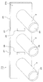
- FIG. 3 is a perspective view of the manifold piping 11 as viewed from the front side.
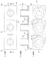
- FIG. 4 is a perspective view of the manifold piping 11 as viewed from the bottom surface side (the seal contact surface 25 side).
- 5A, 5B, and 5C are drawings showing a top view (front view), a cross-sectional view, and a bottom view (back view) of the manifold pipe 11, respectively.
- the manifold pipe 11 in the first embodiment is a plurality of pipes 2 (short) that are first and second connection pipes that can be connected to a fluid pipe outside the fuel cell stack 1. Tube) and a flange 26, which is a plate-like member that connects the respective pipes 2 into an integrated state.
- the pipe 2 is three pipes of reaction gas and cooling water, and one end of each pipe 2 is joined to the flange 26.
- the manifold pipe 11 is integrally formed by injection molding using, for example, resin. 3 to 5 exemplify cases where the respective pipes 2 are formed with the same size and the same shape, but the present invention is not limited thereto.
- each pipe 2 may be deformed such as increasing the inner diameter according to the nature and flow rate of the fluid passing through the pipe 2.
- manifold holes corresponding to the respective pipes 2 are formed on the first surface 26 a (surface on the cell stack 10 side) which is the bottom surface of the flange 26 of the manifold pipe 11. (That is, a hole in the pipe 2) 29 is provided to be opened.
- seal contact surfaces (grooves) 25 are provided around each manifold hole 29 so as to surround the entire periphery of the manifold hole 29.
- the gas seal 15 disposed on the outer periphery of the supply port 18 and the discharge port 19 on the end surface of the cell stack 10 is a groove.
- the seal contact surface 25 is contacted. Thereby, the circumference
- the first surface 26 a of the flange 26 extends between the holes of the adjacent pipes 2, that is, between the manifold holes 29 in a direction orthogonal to the arrangement direction of the pipes 2.
- a groove is provided. This groove portion divides the surrounding area of one adjacent pipe 2 and the surrounding area of the other pipe 2 on the first surface 26a of the flange 26 (that is, divides so that the surface is not continuous).
- the flange 26 is formed so as to be connected from one end edge to the other end edge. Therefore, in the first embodiment, this groove portion is referred to as a division portion 27. Further, each divided portion 27 is formed between the seal contact surfaces 25 around the adjacent pipes 2. Note that the groove-shaped dividing portion 27 of the first embodiment is opened at the edge of the flange 26.
- An opening 28 that penetrates in the thickness direction from the first surface 26 a side of the flange 26 to the second surface 26 b (the back surface side of the first surface 26 a) side is formed on the inner bottom surface of the divided portion 27 (groove portion). Is formed.
- This opening portion 28 is connected to the dividing portion 27, that is, communicated with the inner space of the groove in the dividing portion 27 and is also a part of the dividing portion 27, and has a long hole shape along the extending direction of the dividing portion 27. And is formed near the center in the extending direction.
- the dividing portion 27 has a trapezoidal cross-sectional shape in which the width at the opening edge of the groove is larger than the width at the bottom surface.
- the groove-shaped divided portion 27 is provided between the adjacent pipes 2, so that the surrounding area of one adjacent pipe 2 and the other The area around the pipe 2 can be divided. Therefore, it becomes possible to suppress heat transfer between the fluid flowing in one adjacent pipe 2 and the fluid flowing in the other pipe 2 in the vicinity of the surface on the first surface 26a side, and the heat insulation between the fluids is improved. Can be made. Such suppression of heat transfer between fluids is such that the first surface 26a is not continuous in the divided portion 27, and the cross-sectional area of the flange 26 in the heat transfer direction at the position where the divided portion 27 is provided. This can be realized by reducing the size.
- the opening part 28 which penetrates the flange 26 in the thickness direction between the adjacent pipes 2 is further formed, heat transfer between the pipes 2 can be further suppressed.
- the opening 28 is also opened on the second surface 26b side of the flange 26, heat transfer near the surface of the flange 26 on the second surface 26b side can be suppressed. Therefore, in the manifold piping 11, by providing the flange 26 with the opening 28 in addition to the dividing portion 27, heat transfer from each piping 2 to the other piping 2 can be further suppressed, and the heat insulation effect is improved. There is an effect.
- the split portion 27 is provided on the flange 26, the flatness of the seal contact surface 25 can be increased. Since the first surface 26 a of the flange 26 is divided into three plane regions by the groove-shaped dividing portion 27, the area of each plane region is smaller than the area of the entire flange 26. Therefore, the flatness of each plane area can be increased as compared with the case where the entire flange 26 is formed as one plane area. Further, in the case where the flange 26 is formed by injection molding, since the groove-shaped divided portions 27 are provided, it is possible to reduce the influence of adjacent planar regions on each other, thereby increasing the flatness. Can do.
- the flange 26 is easily deformed at the dividing portion 27, and the flatness at the time of assembling at each seal contact surface 25 is easily secured. Therefore, the sealing performance between the manifold pipe 11 and the cell stack 10 is improved.
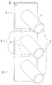
- FIG. 6 shows a manifold pipe 11 showing another example of an opening that penetrates the flange 26 in the thickness direction as a perspective view from the front side.
- the opening 28 is provided at two positions on both ends of the flange 26, not at the center. If the groove-shaped divided portion 27 is formed on the first surface 26a side (the seal contact surface 25 side) of the flange 26 so that the adjacent pipes 2 are discontinuous, in this way, in the vicinity of the center. Alternatively, the opening 28 may be provided at both end edges. However, as shown in FIGS. 3 to 5, the effect of suppressing heat transfer can be further enhanced by providing the opening 28 so as to divide the route where the adjacent pipes 2 have the shortest distance.
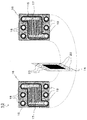
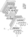
- FIG. 7 is a partially exploded perspective view of the fuel cell stack 51 according to the second embodiment of the present disclosure.
- the fuel cell stack 51 is configured by stacking current collector plates 12, manifold pipes 11, and end plates 4 on both sides of the cell stack 10 and fastening them with bolts and nuts (not shown).
- the fuel cell stack 1 supplies a reactive gas to one end surface (the front side in the figure) of the end surfaces of the cell stack 10 (the outer surface of the separator 16 in the outermost unit cell 13) 2
- One reaction gas supply port and a cooling water supply port for supplying cooling water are formed.
- the other end surface (the back side in the figure) of the end surface of the cell stack (the outer surface of the separator 16 in the outermost unit cell 13) has two reaction gas discharge ports for discharging the reaction gas, and cooling water.
- a cooling water discharge port for discharging the water is formed.
- reaction gas and cooling water which entered from the supply port of reaction gas and the supply port of cooling water flow through the inside or boundary of each unit cell, and are located on the opposite surface (illustration back side) of the cell stack 10. It is discharged from the reaction gas outlet and the cooling water outlet.
- the current collector plate 12 is provided so as to be accommodated in the end plate 4 at a position that does not overlap the positions of the supply port and discharge port of the reaction gas and the supply port and discharge port of the cooling water provided in the cell stack. Yes.
- end plates 4 on both sides have, for example, circular shapes at positions corresponding to the reaction gas supply port, the cooling water supply port, the reaction gas discharge port, and the cooling water discharge port provided in the cell stack 10.
- a through hole 24 is provided.
- reaction gas supply port 18 and the cooling water supply port 18 provided in the external piping and the cell stack 10 through the manifold piping 11.
- the reaction gas outlet 19 and the cooling water outlet 19 are connected to each other.
- a gas seal 15 is disposed around the reaction gas supply port 18, the cooling water supply port 18, the reaction gas discharge port 19, and the cooling water discharge port 19 of the cell stack 10. To be sealed.
- the current collecting plate 12 and the end plate 4 can be configured in the same shape at both ends. The effect that the number can be reduced can be obtained.
- the groove-shaped divided portion 27 formed in the flange 26 of the manifold pipe 11 extends in a direction orthogonal to the arrangement direction of the pipes 2 is described as an example. Not limited to. What is necessary is just to extend in the direction which cross
- the opening 28 is formed on the inner bottom surface of the dividing portion 27
- the dividing portion 27 and the opening 28 may be formed at different positions and not connected to each other. Even when only the groove-shaped divided portion 27 is provided and the opening portion 28 is not provided, the effect of suppressing heat transfer by the divided portion 27 can be obtained. Even if only the opening 28 is provided and the groove-shaped dividing portion 27 is not provided, the effect of suppressing heat transfer by the opening 28 can be obtained.
- the opening 28 preferably has a long hole shape extending in a direction intersecting with the arrangement direction of the pipes 2.
- the division part 27 may be provided on the second surface 26b side.
- the division part 27 may be provided on the second surface 26b side.
- seal contact surface 25 disposed so as to surround the circumference of the pipe 2 on the first surface 26a of the flange 26 is not limited to the groove-shaped form.
- the seal contact surface may be any surface that the gas seal 15 contacts, and a planar contact region that is not a groove shape may be used as the seal contact surface.
- the dividing portion 27 has a trapezoidal cross-sectional shape
- various other cross-sectional shapes may be adopted.
- the cross-sectional shape of the dividing portion 27 so that the width at the opening edge of the groove is larger than the width at the bottom surface, it is easy to perform die cutting when the flange 26 is formed by injection molding.
- stress concentration can be prevented by making the inner surface of the groove
- the cell stack 10 including the unit cell 13 and the end plate 4 is referred to as the cell stack 10.
- the end face of the cell stack 10 may be the end face of the end plate 4.
- a configuration in which the flange 26 of the manifold pipe 11 is disposed on the end surface of the cell stack 10, that is, the end surface of the end plate 4 may be adopted.
- the fuel cell stack of the present disclosure can provide a pipe structure with a high heat insulating effect as well as improved assemblability and sealability by using manifold piping. Therefore, it is considered that this fuel cell is suitable for application to a household cogeneration system or an automobile fuel cell.
Landscapes
- Life Sciences & Earth Sciences (AREA)
- Engineering & Computer Science (AREA)
- Manufacturing & Machinery (AREA)
- Sustainable Development (AREA)
- Sustainable Energy (AREA)
- Chemical & Material Sciences (AREA)
- Chemical Kinetics & Catalysis (AREA)
- Electrochemistry (AREA)
- General Chemical & Material Sciences (AREA)
- Fuel Cell (AREA)
Priority Applications (3)
| Application Number | Priority Date | Filing Date | Title |
|---|---|---|---|
| EP14774349.6A EP2860807B1 (de) | 2013-03-26 | 2014-03-26 | Brennstoffzellenstapel |
| US14/413,092 US20150288020A1 (en) | 2013-03-26 | 2014-03-26 | Fuel cell stack |
| JP2014525214A JP5613865B1 (ja) | 2013-03-26 | 2014-03-26 | 燃料電池スタック |
Applications Claiming Priority (2)
| Application Number | Priority Date | Filing Date | Title |
|---|---|---|---|
| JP2013-063452 | 2013-03-26 | ||
| JP2013063452 | 2013-03-26 |
Publications (1)
| Publication Number | Publication Date |
|---|---|
| WO2014156152A1 true WO2014156152A1 (ja) | 2014-10-02 |
Family
ID=51623165
Family Applications (1)
| Application Number | Title | Priority Date | Filing Date |
|---|---|---|---|
| PCT/JP2014/001754 WO2014156152A1 (ja) | 2013-03-26 | 2014-03-26 | 燃料電池スタック |
Country Status (4)
| Country | Link |
|---|---|
| US (1) | US20150288020A1 (de) |
| EP (1) | EP2860807B1 (de) |
| JP (1) | JP5613865B1 (de) |
| WO (1) | WO2014156152A1 (de) |
Cited By (1)
| Publication number | Priority date | Publication date | Assignee | Title |
|---|---|---|---|---|
| JP2021507108A (ja) * | 2017-12-19 | 2021-02-22 | コミッサリア ア レネルジー アトミーク エ オ ゼネルジ ザルタナテイヴ | Soec/sofc型固体酸化物スタック、圧着システム、および熱交換システムを備えるアセンブリ |
Families Citing this family (5)
| Publication number | Priority date | Publication date | Assignee | Title |
|---|---|---|---|---|
| CN108140865B (zh) * | 2015-10-06 | 2021-08-20 | 本田技研工业株式会社 | 燃料电池堆 |
| GB2561336A (en) * | 2017-03-02 | 2018-10-17 | Lg Fuel Cell Systems Inc | A high temperature fuel cell system and a sealing apparatus |
| CN108417875B (zh) * | 2018-02-09 | 2020-07-14 | 广东国鸿氢能科技有限公司 | 分配歧管和燃料电池电堆组 |
| GB2572989B (en) * | 2018-04-18 | 2020-12-30 | Intelligent Energy Ltd | Thermal managing end plate for fuel cell stack assembly |
| JP7115229B2 (ja) * | 2018-11-07 | 2022-08-09 | トヨタ自動車株式会社 | 燃料電池、燃料電池搭載装置、および燃料電池の製造方法 |
Citations (4)
| Publication number | Priority date | Publication date | Assignee | Title |
|---|---|---|---|---|
| JP2002343406A (ja) * | 2001-05-16 | 2002-11-29 | Toyota Motor Corp | 燃料電池のマニホールド |
| JP2006049129A (ja) * | 2004-08-05 | 2006-02-16 | Honda Motor Co Ltd | 燃料電池スタック |
| JP2010055892A (ja) * | 2008-08-27 | 2010-03-11 | Toyota Motor Corp | 燃料電池 |
| WO2013094454A1 (ja) * | 2011-12-21 | 2013-06-27 | 本田技研工業株式会社 | 燃料電池スタック |
Family Cites Families (3)
| Publication number | Priority date | Publication date | Assignee | Title |
|---|---|---|---|---|
| JP3363781B2 (ja) * | 1998-03-18 | 2003-01-08 | 石川ガスケット株式会社 | 複数のシール部を有する金属板ガスケット |
| JP4684585B2 (ja) * | 2004-07-14 | 2011-05-18 | 本田技研工業株式会社 | 燃料電池スタック |
| JP4820068B2 (ja) * | 2004-08-02 | 2011-11-24 | 本田技研工業株式会社 | 燃料電池スタック |
-
2014
- 2014-03-26 US US14/413,092 patent/US20150288020A1/en not_active Abandoned
- 2014-03-26 WO PCT/JP2014/001754 patent/WO2014156152A1/ja active Application Filing
- 2014-03-26 JP JP2014525214A patent/JP5613865B1/ja active Active
- 2014-03-26 EP EP14774349.6A patent/EP2860807B1/de active Active
Patent Citations (5)
| Publication number | Priority date | Publication date | Assignee | Title |
|---|---|---|---|---|
| JP2002343406A (ja) * | 2001-05-16 | 2002-11-29 | Toyota Motor Corp | 燃料電池のマニホールド |
| JP2006049129A (ja) * | 2004-08-05 | 2006-02-16 | Honda Motor Co Ltd | 燃料電池スタック |
| JP4653978B2 (ja) | 2004-08-05 | 2011-03-16 | 本田技研工業株式会社 | 燃料電池スタック |
| JP2010055892A (ja) * | 2008-08-27 | 2010-03-11 | Toyota Motor Corp | 燃料電池 |
| WO2013094454A1 (ja) * | 2011-12-21 | 2013-06-27 | 本田技研工業株式会社 | 燃料電池スタック |
Non-Patent Citations (1)
| Title |
|---|
| See also references of EP2860807A4 |
Cited By (1)
| Publication number | Priority date | Publication date | Assignee | Title |
|---|---|---|---|---|
| JP2021507108A (ja) * | 2017-12-19 | 2021-02-22 | コミッサリア ア レネルジー アトミーク エ オ ゼネルジ ザルタナテイヴ | Soec/sofc型固体酸化物スタック、圧着システム、および熱交換システムを備えるアセンブリ |
Also Published As
| Publication number | Publication date |
|---|---|
| EP2860807A4 (de) | 2015-06-24 |
| JP5613865B1 (ja) | 2014-10-29 |
| JPWO2014156152A1 (ja) | 2017-02-16 |
| EP2860807A1 (de) | 2015-04-15 |
| US20150288020A1 (en) | 2015-10-08 |
| EP2860807B1 (de) | 2016-09-14 |
Similar Documents
| Publication | Publication Date | Title |
|---|---|---|
| JP5613865B1 (ja) | 燃料電池スタック | |
| US7972741B2 (en) | Diffusion media for seal support for improved fuel cell design | |
| US7759014B2 (en) | Fuel cell having a seal member | |
| CN101483245B (zh) | 用于燃料电池的具有优化尺寸的薄膜 | |
| US20130209909A1 (en) | Fuel cell | |
| JP5593937B2 (ja) | 燃料電池装置 | |
| KR100953273B1 (ko) | 연료전지용 금속 분리판 및 이를 구비하는 연료전지 스택 | |
| JP2002343406A (ja) | 燃料電池のマニホールド | |
| JP2008218087A (ja) | 燃料電池 | |
| CN110600760B (zh) | 燃料电池单元及燃料电池组 | |
| JP7154915B2 (ja) | 燃料電池スタックのマニホールド構造 | |
| JP2007207505A (ja) | 燃料電池 | |
| US8557467B2 (en) | Fuel cell and fuel cell stack | |
| JP5206147B2 (ja) | 固体高分子型燃料電池 | |
| CN107534179B (zh) | 燃料电池堆 | |
| JP2006147258A (ja) | セパレータ及び燃料電池スタック | |
| JP5259888B1 (ja) | 高分子電解質形燃料電池 | |
| JP5443254B2 (ja) | 燃料電池 | |
| JP5740214B2 (ja) | 燃料電池 | |
| JP5332399B2 (ja) | 燃料電池用セパレータ及びそれを用いた燃料電池 | |
| JP5482488B2 (ja) | 燃料電池スタック | |
| US8652700B2 (en) | Fuel cell | |
| CN109478660B (zh) | 燃料电池 | |
| CN117766795A (zh) | 燃料电池堆 | |
| CN109524686B (zh) | 燃料电池分隔件、单体燃料电池、燃料电池电堆和极板 |
Legal Events
| Date | Code | Title | Description |
|---|---|---|---|
| ENP | Entry into the national phase |
Ref document number: 2014525214 Country of ref document: JP Kind code of ref document: A |
|
| 121 | Ep: the epo has been informed by wipo that ep was designated in this application |
Ref document number: 14774349 Country of ref document: EP Kind code of ref document: A1 |
|
| REEP | Request for entry into the european phase |
Ref document number: 2014774349 Country of ref document: EP |
|
| WWE | Wipo information: entry into national phase |
Ref document number: 14413092 Country of ref document: US Ref document number: 2014774349 Country of ref document: EP |
|
| NENP | Non-entry into the national phase |
Ref country code: DE |