US7972741B2 - Diffusion media for seal support for improved fuel cell design - Google Patents
Diffusion media for seal support for improved fuel cell design Download PDFInfo
- Publication number
- US7972741B2 US7972741B2 US11/439,359 US43935906A US7972741B2 US 7972741 B2 US7972741 B2 US 7972741B2 US 43935906 A US43935906 A US 43935906A US 7972741 B2 US7972741 B2 US 7972741B2
- Authority
- US
- United States
- Prior art keywords
- fuel cell
- seal
- cathode
- anode
- active area
- Prior art date
- Legal status (The legal status is an assumption and is not a legal conclusion. Google has not performed a legal analysis and makes no representation as to the accuracy of the status listed.)
- Expired - Fee Related, expires
Links
- 239000000446 fuel Substances 0.000 title claims abstract description 311
- 238000009792 diffusion process Methods 0.000 title claims abstract description 67
- 239000012528 membrane Substances 0.000 claims abstract description 84
- 239000012809 cooling fluid Substances 0.000 claims description 89
- 239000000376 reactant Substances 0.000 claims description 31
- 239000002131 composite material Substances 0.000 claims description 17
- 239000007789 gas Substances 0.000 description 29
- XLYOFNOQVPJJNP-UHFFFAOYSA-N water Substances O XLYOFNOQVPJJNP-UHFFFAOYSA-N 0.000 description 14
- 239000000463 material Substances 0.000 description 7
- 238000007789 sealing Methods 0.000 description 6
- UFHFLCQGNIYNRP-UHFFFAOYSA-N Hydrogen Chemical compound [H][H] UFHFLCQGNIYNRP-UHFFFAOYSA-N 0.000 description 5
- 230000003197 catalytic effect Effects 0.000 description 4
- 230000005611 electricity Effects 0.000 description 4
- QVGXLLKOCUKJST-UHFFFAOYSA-N atomic oxygen Chemical compound [O] QVGXLLKOCUKJST-UHFFFAOYSA-N 0.000 description 3
- 229920001971 elastomer Polymers 0.000 description 3
- 239000000806 elastomer Substances 0.000 description 3
- 239000003792 electrolyte Substances 0.000 description 3
- 239000001257 hydrogen Substances 0.000 description 3
- 229910052739 hydrogen Inorganic materials 0.000 description 3
- 125000004435 hydrogen atom Chemical group [H]* 0.000 description 3
- 239000000203 mixture Substances 0.000 description 3
- 239000001301 oxygen Substances 0.000 description 3
- 229910052760 oxygen Inorganic materials 0.000 description 3
- BASFCYQUMIYNBI-UHFFFAOYSA-N platinum Chemical compound [Pt] BASFCYQUMIYNBI-UHFFFAOYSA-N 0.000 description 3
- 239000007787 solid Substances 0.000 description 3
- OKTJSMMVPCPJKN-UHFFFAOYSA-N Carbon Chemical compound [C] OKTJSMMVPCPJKN-UHFFFAOYSA-N 0.000 description 2
- 239000002826 coolant Substances 0.000 description 2
- 210000004907 gland Anatomy 0.000 description 2
- 229920000554 ionomer Polymers 0.000 description 2
- 238000004519 manufacturing process Methods 0.000 description 2
- 238000000034 method Methods 0.000 description 2
- 230000008450 motivation Effects 0.000 description 2
- 239000002245 particle Substances 0.000 description 2
- 238000009825 accumulation Methods 0.000 description 1
- 230000002378 acidificating effect Effects 0.000 description 1
- 239000000853 adhesive Substances 0.000 description 1
- 230000001070 adhesive effect Effects 0.000 description 1
- 239000006227 byproduct Substances 0.000 description 1
- 229910052799 carbon Inorganic materials 0.000 description 1
- 239000011248 coating agent Substances 0.000 description 1
- 238000000576 coating method Methods 0.000 description 1
- 239000004020 conductor Substances 0.000 description 1
- 230000007423 decrease Effects 0.000 description 1
- 239000013536 elastomeric material Substances 0.000 description 1
- UQSQSQZYBQSBJZ-UHFFFAOYSA-N fluorosulfonic acid Chemical compound OS(F)(=O)=O UQSQSQZYBQSBJZ-UHFFFAOYSA-N 0.000 description 1
- 230000006870 function Effects 0.000 description 1
- 229910002804 graphite Inorganic materials 0.000 description 1
- 239000010439 graphite Substances 0.000 description 1
- 230000002209 hydrophobic effect Effects 0.000 description 1
- 238000012986 modification Methods 0.000 description 1
- 230000004048 modification Effects 0.000 description 1
- 239000002985 plastic film Substances 0.000 description 1
- 229920006255 plastic film Polymers 0.000 description 1
- 229910052697 platinum Inorganic materials 0.000 description 1
- 239000005518 polymer electrolyte Substances 0.000 description 1
- 239000012858 resilient material Substances 0.000 description 1
- 229910001220 stainless steel Inorganic materials 0.000 description 1
- 239000010935 stainless steel Substances 0.000 description 1
- 239000000126 substance Substances 0.000 description 1
Images


Classifications
-
- H—ELECTRICITY
- H01—ELECTRIC ELEMENTS
- H01M—PROCESSES OR MEANS, e.g. BATTERIES, FOR THE DIRECT CONVERSION OF CHEMICAL ENERGY INTO ELECTRICAL ENERGY
- H01M8/00—Fuel cells; Manufacture thereof
- H01M8/02—Details
- H01M8/0271—Sealing or supporting means around electrodes, matrices or membranes
- H01M8/0273—Sealing or supporting means around electrodes, matrices or membranes with sealing or supporting means in the form of a frame
-
- H—ELECTRICITY
- H01—ELECTRIC ELEMENTS
- H01M—PROCESSES OR MEANS, e.g. BATTERIES, FOR THE DIRECT CONVERSION OF CHEMICAL ENERGY INTO ELECTRICAL ENERGY
- H01M8/00—Fuel cells; Manufacture thereof
- H01M8/24—Grouping of fuel cells, e.g. stacking of fuel cells
- H01M8/241—Grouping of fuel cells, e.g. stacking of fuel cells with solid or matrix-supported electrolytes
- H01M8/242—Grouping of fuel cells, e.g. stacking of fuel cells with solid or matrix-supported electrolytes comprising framed electrodes or intermediary frame-like gaskets
-
- H—ELECTRICITY
- H01—ELECTRIC ELEMENTS
- H01M—PROCESSES OR MEANS, e.g. BATTERIES, FOR THE DIRECT CONVERSION OF CHEMICAL ENERGY INTO ELECTRICAL ENERGY
- H01M8/00—Fuel cells; Manufacture thereof
- H01M8/02—Details
- H01M8/0202—Collectors; Separators, e.g. bipolar separators; Interconnectors
- H01M8/0258—Collectors; Separators, e.g. bipolar separators; Interconnectors characterised by the configuration of channels, e.g. by the flow field of the reactant or coolant
-
- H—ELECTRICITY
- H01—ELECTRIC ELEMENTS
- H01M—PROCESSES OR MEANS, e.g. BATTERIES, FOR THE DIRECT CONVERSION OF CHEMICAL ENERGY INTO ELECTRICAL ENERGY
- H01M8/00—Fuel cells; Manufacture thereof
- H01M8/02—Details
- H01M8/0202—Collectors; Separators, e.g. bipolar separators; Interconnectors
- H01M8/0267—Collectors; Separators, e.g. bipolar separators; Interconnectors having heating or cooling means, e.g. heaters or coolant flow channels
-
- H—ELECTRICITY
- H01—ELECTRIC ELEMENTS
- H01M—PROCESSES OR MEANS, e.g. BATTERIES, FOR THE DIRECT CONVERSION OF CHEMICAL ENERGY INTO ELECTRICAL ENERGY
- H01M8/00—Fuel cells; Manufacture thereof
- H01M8/02—Details
- H01M8/0271—Sealing or supporting means around electrodes, matrices or membranes
- H01M8/0276—Sealing means characterised by their form
-
- H—ELECTRICITY
- H01—ELECTRIC ELEMENTS
- H01M—PROCESSES OR MEANS, e.g. BATTERIES, FOR THE DIRECT CONVERSION OF CHEMICAL ENERGY INTO ELECTRICAL ENERGY
- H01M8/00—Fuel cells; Manufacture thereof
- H01M8/24—Grouping of fuel cells, e.g. stacking of fuel cells
- H01M8/2465—Details of groupings of fuel cells
- H01M8/2483—Details of groupings of fuel cells characterised by internal manifolds
-
- Y—GENERAL TAGGING OF NEW TECHNOLOGICAL DEVELOPMENTS; GENERAL TAGGING OF CROSS-SECTIONAL TECHNOLOGIES SPANNING OVER SEVERAL SECTIONS OF THE IPC; TECHNICAL SUBJECTS COVERED BY FORMER USPC CROSS-REFERENCE ART COLLECTIONS [XRACs] AND DIGESTS
- Y02—TECHNOLOGIES OR APPLICATIONS FOR MITIGATION OR ADAPTATION AGAINST CLIMATE CHANGE
- Y02E—REDUCTION OF GREENHOUSE GAS [GHG] EMISSIONS, RELATED TO ENERGY GENERATION, TRANSMISSION OR DISTRIBUTION
- Y02E60/00—Enabling technologies; Technologies with a potential or indirect contribution to GHG emissions mitigation
- Y02E60/30—Hydrogen technology
- Y02E60/50—Fuel cells
Definitions
- This invention relates generally to a fuel cell stack and, more particularly, to a fuel cell stack that includes straight cathode and anode flow channels through a seal area of the fuel cells in the stack so as to reduce water accumulation in the flow channels.
- a hydrogen fuel cell is an electro-chemical device that includes an anode and a cathode with an electrolyte therebetween.
- the anode receives hydrogen gas and the cathode receives oxygen or air.
- the hydrogen gas is dissociated in the anode to generate free hydrogen protons and electrons.
- the hydrogen protons pass through the electrolyte to the cathode.
- the hydrogen protons react with the oxygen and the electrons in the cathode to generate water.
- the electrons from the anode cannot pass through the electrolyte, and thus are directed through a load to perform work before being sent to the cathode.
- PEMFC Proton exchange membrane fuel cells
- the PEMFC generally includes a solid polymer electrolyte proton conducting membrane, such as a perfluorosulfonic acid membrane.
- the anode and cathode typically include finely divided catalytic particles, usually platinum (Pt), supported on carbon particles and mixed with an ionomer.
- Pt platinum
- the catalytic mixture is deposited on opposing sides of the membrane.
- the combination of the anode catalytic mixture, the cathode catalytic mixture and the membrane define a membrane electrode assembly (MEA).
- MEAs are relatively expensive to manufacture and require certain conditions for effective operation.
- a typical fuel cell stack for a vehicle may have two hundred or more stacked fuel cells.
- the fuel cell stack receives a cathode input gas, typically a flow of air forced through the stack by a compressor. Not all of the oxygen is consumed by the stack and some of the air is output as a cathode exhaust gas that may include water as a stack by-product.
- the fuel cell stack also receives an anode hydrogen input gas that flows into the anode side of the stack.
- the fuel cell stack includes a series of bipolar plates positioned between the several MEAs in the stack, where the bipolar plates and the MEAs are positioned between two end plates.
- the bipolar plates include an anode side and a cathode side for adjacent fuel cells in the stack.
- Anode gas flow channels are provided on the anode side of the bipolar plates that allow the anode reactant gas to flow to the respective MEA.
- Cathode gas flow channels are provided on the cathode side of the bipolar plates that allow the cathode reactant gas to flow to the respective MEA.
- One end plate includes anode gas flow channels, and the other end plate includes cathode gas flow channels.
- the bipolar plates and end plates are made of a conductive material, such as stainless steel or a conductive composite. The end plates conduct the electricity generated by the fuel cells out of the stack.
- the bipolar plates also include flow channels through which a cooling fluid flows.
- the bipolar plates are made of a composite material, such as graphite, where two plate halves are separately molded and then glued together so that anode flow channels are provided at one side of one of the plate halves, cathode flow channels are provided at an opposite side of the other plate half and cooling fluid flow channels are provided between the plate halves.
- two separate plate halves are stamped and then welded together so that anode flow channels are provided at one side of one of the plate halves, cathode flow channels are provided at an opposite side of the other plate half and cooling fluid flow channels are provided between the plate halves.
- the membranes within a fuel cell need to have a certain relative humidity so that the ionic resistance across the membrane is low enough to effectively conduct protons.
- moisture from the MEAs and external humidification may enter the anode and cathode flow channels.
- the water may accumulate within the flow channels because the flow rate of the reactant gas is too low to force the water out of the channels.
- the water forms droplets that continue to expand because of the relatively hydrophobic nature of the plate material. The droplets form in the flow channels substantially perpendicular to the flow of the reactant gas.
- the flow channel is closed off, and the reactant gas is diverted to other flow channels because the channels are in parallel between common inlet and outlet manifolds. Because the reactant gas may not flow through a channel that is blocked with water, the reactant gas cannot force the water out of the channel. Those areas of the membrane that do not receive reactant gas as a result of the channel being blocked will not generate electricity, thus resulting in a non-homogenous current distribution and reducing the overall efficiency of the fuel cell. As more and more flow channels are blocked by water, the electricity produced by the fuel cell decreases, where a cell voltage potential less than 200 mV is considered a cell failure. Because the fuel cells are electrically coupled in series, if one of the fuel cells stops performing, the entire fuel cell stack may stop performing.
- a fuel cell stack typically includes a seal that extends around the active area of the stack and between the stack headers and the active area for each fuel cell to prevent gas leakage from the stack. Therefore, in order to get the cathode flow, the anode flow and the cooling fluid flow from the respective inlet header into the active area of the fuel cell, it is necessary for the flow channels to go through the seal area without affecting seal integrity.
- Typically holes are provided through the bipolar plate around the seals, which requires a bend in the flow channels so that they line up with the flow channels in the active area. This bend in the cathode and anode flow channels provided an area that water could accumulate and be trapped which had a tendency to close the flow channel and reduce the flow of reactant gas thereto. Therefore, a better technique for traversing the seal area of the fuel cell stack is needed.
- a fuel cell stack that includes straight cathode flow channels and anode flow channels through a seal area between bipolar plates in the stack.
- the fuel cell stack includes a seal that extends around the active area of the fuel cells in the stack and between the stack headers and the active area.
- the diffusion media layer on one side of the membrane is extended to provide the seal load.
- FIG. 1 is a cross-sectional view of a fuel cell stack including composite bipolar plates, according to an embodiment of the present invention
- FIG. 2 is a cross-sectional view through line 2 - 2 of the fuel cell stack shown in FIG. 1 ;
- FIG. 3 is a cross-sectional view through line 3 - 3 of the fuel cell stack shown in FIG. 1 ;
- FIG. 4 is a cross-section view through line 4 - 4 of the fuel cell stack shown in FIG. 1 ;
- FIG. 5 is a cross-sectional view through line 5 - 5 of the fuel cell stack shown in FIG. 1 ;
- FIG. 6 is a cross-sectional view through line 6 - 6 of the fuel cell stack shown in FIG. 1 ;
- FIG. 7 is a cross-sectional view through line 7 - 7 of the fuel cell stack shown in FIG. 1 ;
- FIG. 8 is a cross-sectional view of a fuel cell stack including composite bipolar plates and header seal loops, according to another embodiment of the present invention.
- FIG. 9 is a cross-sectional view through line 9 - 9 of the fuel cell stack shown in FIG. 8 ;
- FIG. 10 is a cross-sectional view through line 2 - 2 of the fuel cell stack shown in FIG. 1 , where the fuel cell stack includes composite bipolar plates and shims;
- FIG. 11 is a cross-sectional view through line 3 - 3 of the fuel cell stack shown in FIG. 1 that includes composite bipolar plates and shims;
- FIG. 12 is a cross-sectional view through line 4 - 4 of the fuel cell stack shown in FIG. 1 that includes composite bipolar plates and shims;
- FIG. 13 is a cross-sectional view through line 5 - 5 of the fuel cell stack shown in FIG. 1 that includes composite bipolar plates and shims;
- FIG. 14 is a cross-sectional view through line 6 - 6 of the fuel cell stack shown in FIG. 1 that includes composite bipolar plates and shims;
- FIG. 15 is a cross-sectional view through line 7 - 7 of the fuel cell stack shown in FIG. 1 that includes composite bipolar plates and shims;
- FIG. 16 is a cross-sectional view of a fuel cell stack including stamped bipolar plates, according to another embodiment of the present invention.
- FIG. 17 is a cross-sectional view through line 17 - 17 of the fuel cell stack shown in FIG. 16 ;
- FIG. 18 is a cross-sectional view through line 18 - 18 of the fuel cell stack shown in FIG. 16 ;
- FIG. 19 is a cross-sectional view trough line 19 - 19 of the fuel cell stack shown in FIG. 16 ;
- FIG. 20 is a cross-sectional view through line 20 - 20 of the fuel cell stack shown in FIG. 16 ;
- FIG. 21 is a cross-sectional view through line 21 - 21 of the fuel cell stack shown in FIG. 16 ;
- FIG. 22 is a cross-sectional view through line 22 - 22 of the fuel cell stack shown in FIG. 16 ;
- FIG. 23 is a cross-sectional view of a fuel cell stack including stamped bipolar plates and header seal loops, according to another embodiment of the present invention.
- FIG. 24 is a cross-sectional view through line 24 - 24 of the fuel cell stack shown in FIG. 23 ;
- FIG. 25 is a cross-sectional view through line 17 - 17 of the fuel cell stack shown in FIG. 16 , where the stack includes stamped bipolar plates and shims;
- FIG. 26 is a cross-sectional view through line 18 - 18 of the fuel cell stack shown in FIG. 16 , where the stack includes stamped bipolar plates and shims;
- FIG. 27 is a cross-sectional view through line 19 - 19 of the fuel cell stack shown in FIG. 16 , where the stack includes stamped bipolar plates and shims;
- FIG. 28 is a cross-sectional view through line 20 - 20 of the fuel cell stack shown in FIG. 16 , where the stack includes stamped bipolar plates and shims;
- FIG. 29 is a cross-sectional view through line 21 - 21 of the fuel cell stack shown in FIG. 16 , where the stack includes stamped bipolar plates and shims;
- FIG. 30 is a cross sectional view through line 22 - 22 of the fuel cell stack shown in FIG. 16 , where the stack includes stamped bipolar plates and shims;
- FIG. 31 is a cross-sectional view of a fuel cell stack including stamped bipolar plates, where the bipolar plates provide the seal for the stack, according to another embodiment of the present invention.
- FIG. 32 is a cross-sectional through line 32 - 32 of the fuel cell stack shown in FIG. 31 ;
- FIG. 33 is a cross-sectional view through line 33 - 33 of the fuel cell stack shown in FIG. 31 ;
- FIG. 34 is a cross-sectional view through line 34 - 34 of the fuel cell stack shown in FIG. 31 ;
- FIG. 35 is a cross-sectional view through line 35 - 35 of the fuel stack shown in FIG. 31 ;
- FIG. 36 is a cross-sectional view through line 36 - 36 of the fuel cell stack shown in FIG. 31 ;
- FIG. 37 is a cross-sectional view through line 37 - 37 of the fuel cell stack shown in FIG. 31 ;
- FIG. 38 is a cross-sectional view of a fuel cell stack including stamped bipolar plates and header seal loops, where the bipolar plates provide the seal for the stack, according to another embodiment of the present invention.
- FIG. 39 is a cross-sectional view through line 39 - 39 of the fuel cell stack shown in FIG. 38 ;
- FIG. 40 is a cross-sectional view through line 32 - 32 of the fuel cell stack shown in FIG. 31 , where the stack includes stamped bipolar plates and shims, and where the bipolar plates provide the seal for the stack;
- FIG. 41 is a cross-sectional view through line 33 - 33 of the fuel cell stack shown in FIG. 31 , where the stack includes stamped bipolar plates and shims, and where the bipolar plates provide the seal for the stack;
- FIG. 42 is a cross-sectional view through line 34 - 34 of the fuel cell stack shown in FIG. 31 , where the stack includes stamped bipolar plates and shims, and where the bipolar plates provide the seal for the stack;
- FIG. 43 is a cross-sectional view through line 35 - 35 of the fuel cell stack shown in FIG. 31 , where the stack includes stamped bipolar plates and shims, and where the bipolar plates provide the seal for the stack;
- FIG. 45 is a cross-sectional view through line 37 - 37 of the fuel cell stack shown in FIG. 31 , where the stack includes stamped bipolar plates and shims, and where the bipolar plates provide the seal for the stack.
- FIG. 1 is a cross-sectional view through a fuel cell 50 of a fuel cell stack 10 , where the stack 10 includes an active area 12 and composite bipolar plates.
- the stack 10 includes a cathode inlet header 14 that receives a cathode reactant gas flow and a cathode outlet header 16 that receives a cathode outlet gas flow, where the cathode gas flows through flow channels in the active area 12 .
- the stack 10 also includes an anode inlet header 18 that receives an anode reactant gas flow and an anode outlet header 20 that receives an anode exhaust gas flow, where anode flow channels extend through the active area 12 .
- the stack 10 also includes a cooling fluid inlet header 22 that receives a cooling fluid and a cooling fluid outlet header 24 that outputs the cooling fluid from the stack 10 , where the cooling fluid flows through cooling fluid channels through the active area 12 , as is well understood in the art.
- a seal 30 is provided around the perimeter of the fuel cell 50
- a seal 32 is provided between the cathode inlet header 14 and the active area 12
- a seal 34 is provided between the cathode outlet header 16 and the active area 12
- a seal 36 is provided between the anode inlet header 18 and the active area 12
- a seal 38 is provided between the anode outlet header 20 and the active area 12
- a seal loop 40 is provided around the cooling fluid inlet header 22
- a seal loop 42 is provided around the cooling fluid outlet header 24 .
- the seals can be made of any suitable elastomeric or resilient material.
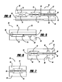
- FIG. 2 is a cross-sectional view through line 2 - 2 of the fuel cell 50 .
- the fuel cell 50 includes an anode side composite bipolar plate 52 and a cathode side composite bipolar plate 54 .
- the bipolar plates shown in the figures are bipolar plate halves in that the bipolar plate half for the adjacent fuel cell is not shown.
- the fuel cell 50 also includes an anode side diffusion media layer 56 , a cathode side diffusion media layer 58 and a membrane 60 therebetween.
- the anode side bipolar plate 52 includes anode flow channels 62 and the cathode side bipolar plate 54 includes part of cooling fluid flow channels 64 , where the other half of the cooling fluid flow channels is provided by the other plate half.
- the seal 32 is positioned in a channel 66 in the anode side bipolar plate 52 .
- the seal would be thicker and the membrane 60 would follow a curved path around the seal.
- the membrane 60 extends straight through the seal area and the cathode side diffusion media layer 58 has been extended to an outer edge of the cathode side bipolar plate 54 .
- the extended diffusion media layer 58 provides seal integrity at the cathode side of the seal area.
- cathode flow channels 68 extending from the cathode inlet header 14 to the active area 12 are straight.
- the seal area between the cathode outlet header 16 and the active area 12 would look the same.
- FIG. 3 is a cross-sectional view through line 3 - 3 of the fuel cell stack 10 showing the seal area between the anode inlet header 18 and the active area 12 of the fuel cell 50 .
- the seal 36 is narrower and the anode side diffusion media layer 56 has been extended to an outer edge of the anode side bipolar plate 52 .
- the extended diffusion media layer 56 provides seal integrity at the anode side of the seal area.
- the anode flow channels 62 extending from the header 18 to the active area 12 are straight. The seal area between the anode outlet header 20 and the active area 12 would look the same.
- FIG. 4 is a cross-sectional view through line 4 - 4 of the fuel cell stack 10 showing the seal area between the cooling fluid inlet header 22 and the active area 12 .
- the seal 30 includes cathode and anode seal halves 72 and 74 and the seal 40 includes cathode and anode seal halves 76 and 78 .
- Straight flow cooling fluid channels 64 are provided from the cooling fluid inlet header 22 to the active area 12 through the seal area.
- the cross-sectional view of the fuel cell 50 at this location would be nearly the same as some of those known in the art.
- the seal area between the cooling fluid outlet header 24 and the active area 12 would look the same.
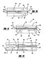
- FIG. 5 is a cross-sectional view through line 5 - 5 showing a joint sealing area between the cathode outlet header 16 and the active area 12 .
- a gap 70 may be created between the diffusion media layer 58 and the seal 30 where the diffusion media layer 58 is supporting the seal on the opposite side of the membrane 60 .
- the gap 70 itself is not a sealing issue as flow is passing through this region anyway. It may be necessary to provide a continuous surface for the seal on the opposite side of the membrane 60 to seal against.
- a filling material may be provided in the gap 70 to provide seal support.
- the filling material may be an elastometer that cures in place after the seal 30 and the diffusion media layer 58 have been positioned.
- a membrane with sub-gaskets support is sufficiently stiff, it can bridge the gap 70 without loss of seal function, and a fill material may not be required.
- An alternative solution for dealing with the gap 70 is to nest the header seal as a complete loop within a separate and continuous perimeter loop. At this location, the diffusion media layer 58 has been extended, as discussed above.
- FIG. 6 is a cross-sectional view through line 6 - 6 of the fuel cell stack 10 at an edge of the active area 12 .
- the seal 30 includes the two seal halves 72 and 74 .
- the cross-sectional view of the fuel cell 50 at this location would also be about the same as some of those known in the art.
- FIG. 7 is a cross-sectional view through line 7 - 7 of the fuel cell stack 10 at an outer edge of the cathode outlet header 16 .
- the seal 30 includes the two seal halves 72 and 74 .
- the cross-sectional view of the fuel cell 50 at this location would also be about the same as some of those known in the art.
- the diffusion media layers carry the seal load across the channels in their reactant gas inlet and outlet regions. If necessary, the diffusion media layer in the seal support region can be filled to provide additional stiffness. This allows direct channels into the active area 12 without tunnels or ports, and does not require that holes be fabricated into the plate or additional bridge inserts be provided. Eliminating the ports and tunnels in the plates will improve water management as water has been found to accumulate in these places. Further, eliminating the holes in the plates simplifies the plate fabrication. Without tunnels, only one side of the plate needs to have a hydrophilic coating applied thereto.
- both reactant gases are sealed.
- the cathode reactant gas can flow through the anode seal where there is no cathode seal, so a flow path from the cathode inlet header 14 to the cathode outlet header 16 is provided.
- the anode reactant gas flow can pass the cathode seal where there is no anode seal, so a flow path from the anode inlet header 18 to the anode outlet header 20 is provided.
- the cooling fluid flow path is independently defined from the reactant flow pattern so that the cooling fluid channels 64 can pass between the seals without affecting the sealing surface on the reactant gas sides.
- the two plate halves would be bonded together to prevent leakage of cooling fluid from between the plate halves.
- this bond is not shown as the plate halves would typically be bonded over the entire plate-to-plate interface surface to ensure low electrical contact resistance between the two bipolar plate halves.
- FIG. 8 is a cross-sectional view of a fuel cell stack 80 through a fuel cell 82 , where like elements to the fuel cell stack 10 are identified by the same reference numeral.
- the seal 32 at the cathode inlet header 14 is replaced with a seal loop 84
- the seal 34 at the cathode outlet header 16 is replaced with a seal loop 86
- the seal 36 at the anode inlet header 18 is replaced with a seal loop 88
- the seal 38 at the anode outlet header 20 is replaced with a seal loop 90 .
- FIG. 9 is a cross-sectional view through line 9 - 9 of the fuel cell stack 80 , according to an embodiment of the present invention.
- the fuel cell 82 includes an anode side bipolar plate 92 , a cathode side bipolar plate 94 , and a membrane 96 therebetween. Because the cathode side diffusion media layer 98 would extend to the edge of the header 16 , the diffusion media layer 98 is shown extending through the seal area provided by the seal loop 86 to provide the continuous seal integrity.
- shims between the seal and the membrane at the seal area.
- a separate shim could be used in this region in place of extending the diffusion media layer for seal support.
- a thicker shim about 0.1 mm
- the shim could be continuous around the seal perimeter. It may be preferable that the shims and seals be bonded to the membrane. This approach could use shims on both sides, or only on one side.
- Thinner sub-gaskets may be used on one or both sides as required to provide the desired active area edge architecture. If only one shim were used, a sub-gasket would be desired on the opposite side of the membrane if material requirements do not allow membranes and seals to have direct contact.
- a span region may be provided. This simply means that the span created by the gasket gland should be smaller than a typical channel span (0.5-1.5 mm) as the shim must provide adequate stiffness to support across a channel span. If the seals are bonded to the shims and the membrane, the seal itself will provide additional stiffness to the sealing surface as this surface would be against the plate, and not the membrane, in this configuration. Because these are shim supported rather than diffusion media supported seals, the channels in this region may be deeper at the shim because the shim is not as thick as the diffusion media layer. The channel bottom could also rise in this region to maintain channel size.
- membranes have a thin (25 ⁇ m) sub-gasket (plastic film) on both sides around the perimeter for mechanical strength and to avoid direct contact between the acidic ionomer membrane and the plate or seals.
- shims for the invention could involve using a thicker sub-gasket(s) to provide adequate stiffness to span channels and support seal loads.
- FIGS. 10-15 show cross-sectional views through a fuel cell 110 of a fuel cell stack that would be similar to the fuel stack 10 where the various headers are provided at the same location of the fuel cell stack and identified with the same reference numeral.
- FIG. 10 represents a cross-sectional view at location 2 - 2 of the fuel cell 110
- FIG. 11 represents a cross-sectional view at location 3 - 3 of the fuel cell 110
- FIG. 12 represents a cross-sectional view at location 4 - 4 of the fuel cell 110
- FIG. 13 represents a cross-sectional view through location 5 - 5 of the fuel cell 110
- FIG. 14 represents a cross-sectional view at location 6 - 6 of the fuel cell 110
- FIG. 15 represents a cross-sectional view of the fuel cell 110 at location 7 - 7 .
- FIG. 10 shows the seal area between the active area 12 of the fuel cell 110 and the cathode inlet header 14 .
- the fuel cell 110 includes an anode side bipolar plate 112 , a cathode side bipolar plate 114 and a membrane 116 therebetween.
- An anode side diffusion media layer 118 is provided between the bipolar plate 112 and the membrane 116 on the anode side and a cathode side diffusion media layer 120 is provided between the membrane 116 and the bipolar plate 114 on the cathode side.
- Anode flow channels 132 are provided in the anode side bipolar plate 112 and cooling fluid flow channels 134 are provided in the cathode side bipolar plate 114 .
- a shim 122 is provided between the membrane 116 and an anode seal 124 at the seal area and a shim 126 is provided between the membrane 116 and a raised portion 128 of the cathode side bipolar plate 114 .
- Cathode flow channels 130 extend through the raised portion 128 and provides a straight flow through the seal area to the active area 12 of the fuel cell 110 .
- the combination of the shim 126 and the raised portion 128 maintain the seal integrity of the cathode side of the fuel cell 110 at this location.
- FIG. 11 shows the seal area between the active area 12 of the fuel cell 110 and the anode inlet header 18 where the anode side bipolar plate 112 includes a raised portion 140 .
- the combination of the raised portion 140 and the shim 122 provides the structure to maintain the seal integrity at this area so that the anode flow channels 132 have a straight flow through the seal area of anode header 18 to the active area of the fuel cell 110 .
- the cathode side bipolar plate 114 includes a channel 144 in which a seal 146 is positioned.
- FIG. 12 shows shims 152 and 154 between seal halves 148 and 150 and the membrane 116 at the cooling fluid inlet header 22 .
- the cooling fluid flow channels 134 are shown in this cross-section.
- FIG. 13 shows shims 160 and 162 between the membrane 116 and seals 164 and 166 at the joint area between the cooling fluid outlet header 24 and the cathode outlet header 14 .
- FIG. 14 shows shims 170 and 172 between the membrane 116 and seal halves 174 and 176 at the outer edge of the active area of the fuel cell 110 .
- FIG. 15 shows shims 180 and 182 between seal halves 184 and 186 and the membrane 116 at an outer edge of the cathode outlet header 16 .
- FIG. 16 is a cross-sectional view of a fuel cell stack 200 through a fuel cell 202 of the stack 200 .
- the fuel cell stack 200 includes stamped bipolar plates.
- the fuel cell stack 200 includes an active area 204 , a cathode inlet header 206 , a cathode outlet header 208 , an anode inlet header 210 , an anode outlet header 212 , a cooling fluid inlet header 214 , and a cooling fluid outlet header 216 .
- the fuel cell stack 200 could include bonds that cross the seals, as is well understood to those skilled in the art.
- a seal 220 extends around an outer perimeter of the fuel cell 202 .
- a seal 222 is provided between the cathode inlet header 206 and the active area 204
- a seal 224 is provided between the cathode outlet header 208 and the active area 204
- a seal 226 is provided between the anode inlet header 210 and the active area 204
- a seal 228 is provided between the anode outlet header 212 and the active area 204
- a seal 230 is provided between the cooling fluid inlet header 214 and the active area 204
- a seal 232 is provided between the cooling fluid outlet header 216 and the active area 204 .
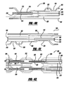
- FIG. 17 is a cross-sectional view through line 17 - 17 of the fuel cell 200 .
- the fuel cell 200 includes an anode side stamped bipolar plate 240 and a cathode side stamped bipolar plate 242 .
- the bipolar plates shown are bipolar plates halves in that the stamped bipolar plate for the adjacent fuel cell is not shown.
- the fuel cell 200 includes an anode side diffusion media layer 244 , a cathode side diffusion media layer 246 and a membrane 248 therebetween.
- the anode side bipolar plate 240 includes anode flow channels 250 and part of cooling fluid flow channels 252 , where the other half of the cooling fluid flow channels are provided by the other plate half. Plate bonds 238 are provided to bond the bipolar plates together.
- the seal 222 is provided at an outer edge of the anode side of the bipolar plate 240 . According to the invention, the seal 222 is thinner than the seal that would normally be present at this location so that the membrane 248 is straight through the seal area. Further, the cathode side diffusion media layer 246 has been extended to an outer edge of the cathode side bipolar plate 242 to provide seal integrity at the cathode side of the seal area. By extending the diffusion media 246 in this manner, cathode flow channels 254 can be straight through the seal area into the active region 204 to reduce areas where water can accumulate in the flow channels 254 . The seal area between the cathode outlet header 208 and the active area 204 would look the same.
- FIG. 18 is a cross-sectional view through line 18 - 18 of the fuel cell stack 200 showing the seal area between the anode inlet header 210 and the active area 204 of the fuel cell 202 .
- the seal 226 is reduced in thickness from the seal that would normally be provided at this location so that the membrane 248 extends straight through the seal area from the active region 204 .
- the anode side diffusion media layer 244 is extended through the seal area so that the anode flow channels 250 extend straight through the seal area for the purposes discussed above.
- the seal area between the anode outlet header 212 and the active area 204 would look the same.
- FIG. 19 is a cross-sectional view through line 19 - 19 of the fuel cell stack 200 showing the seal area between the cooling fluid inlet header 214 and the active area 204 .
- the thickness of the seals 230 and 220 are reduced so that the membrane 248 extends straight through the seal area from the cooling fluid inlet header 214 to the active area 204 .
- the seal area between the cooling fluid outlet header 216 and the active area 204 would look the same.
- FIG. 20 is a cross-sectional view through line 20 - 20 of the fuel cell stack 200 showing a joint sealing area between the cathode outlet header 208 and the active area 204 .
- the anode side diffusion media layer 246 has been extended to the seal 220 , as shown.
- a gap 264 is provided between the diffusion media layer 246 and the seal 220 , and can be filled with appropriate filling material.
- the membrane 248 extends straight through the seal area.
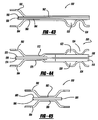
- FIG. 21 is a cross-sectional view through line 21 - 21 of the fuel cell stack 200 at an edge section of the fuel cell 202 .
- the seal 220 includes two seal halves 270 and 272 that allow the membrane 248 to extend straight through the seal area into the active area 204 .
- FIG. 22 is a cross-sectional view through line 22 - 22 of the fuel cell stack 200 at an outer edge portion of the cathode outlet header 208 .
- the seal 220 is made of the two seal halves 270 and 272 to provide the straight membrane 248 through the seal area.
- a bond is shown where the plate halves need to be sealed together to prevent cooling fluid leakages. This could be done using a welded or adhesive bond.
- the bond lines For stamped plates with elastomer seals, an option would be for the bond lines to traverse the seal glands. To ensure adequate seal support for the stamped plates, the plate halves contact each other on either side of the seal. In the cooling fluid inlet header 214 , the cooling fluid flow path is provided so that the plate halves shown by the dotted lines show this. The cooling fluid can flow through because the path is not blocked by the plates.
- the cathode seal is shown to be more inboard on both ends, but seal order with respect to the flow direction is not critical and may be defined based on other requirements.
- FIG. 23 is a cross-sectional view of a fuel cell stack 280 through a fuel cell 282 , where like elements to the fuel cell stack 200 are identified by the same reference numeral, according to another embodiment of the present invention.
- the seal 222 at the cathode inlet header 206 is replaced with a seal loop 286
- the seal 224 at the cathode outlet header 208 is replaced with a seal loop 288
- the seal 226 at the anode inlet header 210 is replaced with a seal loop 290
- the seal 228 at the anode outlet header 212 is replaced with a seal loop 292
- the seal 230 at the cooling fluid inlet header 214 is replaced with seal loops 294 and 296
- the seal 232 at the cooling fluid outlet header 216 is replaced with seal loops 298 and 300 .
- the header loops is to avoid joints, such as shown by FIG. 20 , which only appear at the corners of the reactant headers adjoining the active area, the coolant headers can be maintained without loops, as shown in FIG. 16 .
- FIG. 24 is a cross-sectional view through line 24 - 24 of the fuel cell stack 280 .
- the fuel cell 282 includes an anode side bipolar plate 302 , a cathode side bipolar plate 304 and a membrane 306 therebetween.
- a cathode side diffusion media layer 308 is shown extending through the seal area provided by the seal loop 288 to provide the continuous seal integrity.
- the outer seal loop 220 is made up of two seal halves 310 and 312 at this location.
- FIGS. 25-30 show cross-sectional views through a fuel cell 320 of a fuel cell stack that would be similar to the fuel cell stack 200 where the various headers are provided at the same location of the fuel cell stack.
- FIG. 25 represents a cross-sectional view at location 17 - 17 of the fuel cell 320
- FIG. 26 represents a cross-sectional view at location 18 - 18 of the fuel cell 320
- FIG. 27 represents a cross-sectional view at location 19 - 19 of the fuel cell 320
- FIG. 25 represents a cross-sectional view at location 17 - 17 of the fuel cell 320
- FIG. 26 represents a cross-sectional view at location 18 - 18 of the fuel cell 320
- FIG. 27 represents a cross-sectional view at location 19 - 19 of the fuel cell 320
- FIG. 25 represents a cross-sectional view at location 17 - 17 of the fuel cell 320
- FIG. 26 represents a cross-sectional view at location 18 - 18 of the fuel cell 320
- FIG. 28 represents a cross-sectional view at location 20 - 20 of the fuel cell 320
- FIG. 29 represents a cross-sectional view at location 21 - 21 of the fuel cell 320
- FIG. 30 represents a cross-sectional view at location 22 - 22 of the fuel cell 320 .
- the fuel cell 320 includes an anode side stamped bipolar plate 322 , a cathode side stamped bipolar plate 324 and a membrane 326 therebetween.
- An anode side diffusion media layer 328 is provided between the bipolar plate 322 and the membrane 326 and a cathode side diffusion media layer 330 is provided between the membrane 326 and the bipolar plate 324 .
- the anode side bipolar plate 322 defines anode side flow channels 340 and cooling fluid channels 342 .
- a shim 332 is provided between the membrane 326 and a seal 334 at the seal area and a shim 336 is provided between the membrane 326 and a raised portion 338 of the cathode side bipolar plate 324 .
- Cathode flow channels 344 extend around the raised portion 338 and provide a straight flow through the seal area to the active area of the fuel cell 320 .
- the combination of the shim 336 and the raised portion 338 maintain the seal integrity of the cathode side of the fuel cell 320 at this location.
- FIG. 26 shows a seal area between the active area of the fuel cell 320 and the anode inlet header where the anode side bipolar plate 322 includes a raised portion 346 .
- a shim 348 is provided between the raised portion 346 and the membrane 326 and a shim 350 is provided between the membrane 326 and a seal 352 .
- the combination of the raised portion 346 and the shim 348 provides the structure to maintain the seal integrity at this area so that the anode flow channels 340 have a straight line flow through the seal area from the anode inlet header to the active area of the fuel cell 320 .
- FIG. 27 shows shims 354 between the seal 220 and the anode side bipolar plate 322 , a shim 356 between the membrane 326 and the anode side bipolar plate 322 and a shim 358 between the membrane 326 and the seal 230 .
- FIG. 28 shows a shim 360 between the seal 224 and the membrane 326 and a shim 362 between the seal 220 and the membrane 326 .
- FIG. 29 shows a shim 364 between the seal 270 and the membrane 326 and a shim 366 between the membrane 326 and the seal 272 .
- FIG. 30 shows a shim 368 between the seal half 270 and the membrane 326 , and a shim 370 between the membrane 326 and the seal half 272 .
- FIG. 31 is a cross-sectional view of a fuel cell stack 380 through a fuel cell 382 .
- the fuel cell stack 380 includes stamped bipolar plates, where the plates themselves provide the seal.
- the fuel cell stack 380 includes an active area 384 , a cathode inlet header 386 , a cathode outlet header 388 , an anode inlet header 390 , an anode outlet header 392 , a cooling fluid inlet header 394 and a cooling fluid outlet header 396 .
- a seal 398 extends around the perimeter of the fuel cell 382 .
- a seal 400 is provided between the cathode inlet header 386 and the active area 384 , a seal 402 is provided between the cathode outlet header 388 and the active area 384 , a seal 404 is provided between the anode inlet header 390 and the active area 384 , a seal 406 is provided between the anode outlet header 392 and the active area 384 , a seal 408 is provided between the cooling fluid inlet header 394 and the active area 384 and a seal 410 is provided between the cooling fluid outlet header 396 and the active area 384 .
- all of the seals in this design are provided by the configuration of the bipolar plate.
- FIG. 32 is a cross-sectional view through line 32 - 32 of the fuel cell 382 .
- the fuel cell 382 includes an anode side stamped bipolar plate 420 and a cathode side stamped bipolar plate 422 .
- the fuel cell 382 also includes an anode side diffusion media layer 424 and a cathode side diffusion media layer 426 with a membrane 428 therebetween.
- the anode side bipolar plate 420 includes anode flow channels 430 and half of cooling fluid flow channels 432 , where the other half of the cooling fluid flow channels is provided by the other stamped plate half.
- the seal 400 is defined by a section of the anode side bipolar plate 420 .
- the cathode side diffusion media layer 426 is extended through the seal area opposite to the seal 400 to provide the seal integrity at this side of the membrane 428 .
- cathode flow channels 434 can extend straight through the seal area from the cathode inlet header 386 to the active area 384 so that they do not have to jog around plate components that would act to collect water.
- the seal area between the cathode outlet header 388 and the active area 384 would look the same.
- FIG. 33 is a cross-sectional view through line 33 - 33 of the fuel cell 382 showing the seal area between the anode inlet header 390 and the active area 384 of the fuel cell stack 380 .
- the anode side diffusion media layer 424 is extended at this location to provide the seal integrity at the anode side of the fuel cell 382 opposite to the seal 404 provided by the structural configuration of the bipolar plate 422 .
- the seal area between the anode outlet header 392 and the active area 384 would look the same.
- FIG. 34 is a cross-sectional view through line 34 - 34 of the fuel cell stack 380 showing the seal area between the cooling fluid inlet header 394 and the active area 384 .
- the anode side bipolar plate 420 and the cathode side bipolar plate 422 provide the seals 408 and 398 .
- the cooling fluid flow channels 432 extend through the plate in a straight flow through the seal area to the active area 384 . Because the plates 420 and 422 provide the seals in this embodiment, this brings adjacent bipolar plates into electrical contact at certain locations in the fuel cell 382 and would create an electrical short. Therefore, a non-conductive separator 438 is provided at the seal location 408 to prevent electrical shorting.
- the seal area between the cooling fluid outlet header 396 and the active area 384 would look the same.
- FIG. 35 is a cross-sectional view through line 35 - 35 at a joint sealing area between the cathode outlet header 388 and the active area 384 .
- the cathode side diffusion media layer 426 is extended at this location for the anode side bipolar plate 420 and the cathode side bipolar plate 422 define the seals 402 and 398 .
- a gap 440 between the diffusion media layer 426 and the seal portion of the plate 422 may need to be filled with a suitable material.
- FIG. 36 is a cross-sectional view at an edge section of the fuel cell 382 , and would be similar to the edge section of the known fuel cell stacks that include stamped bipolar plates with stamped seals.
- FIG. 37 is a cross-sectional view through line 37 - 37 of the fuel cell stack 380 at an outer edge of the cathode outlet header 388 .
- the seal 398 is provided by the anode side bipolar plate 420 and the cathode side bipolar plate 422 .
- FIG. 38 is a cross-sectional view of a fuel cell stack 450 through a fuel cell 452 , where like elements to the fuel cell stack 380 are identified by the same reference numeral.
- the seal 400 at the cathode inlet header 386 is replaced with a seal loop 454
- the seal 402 at the cathode outlet header 388 is replaced with a seal loop 456
- the seal 404 at the anode inlet header 390 is replaced with a seal loop 458
- the seal 406 at the anode outlet header 392 is replaced with a seal loop 460
- the seal 408 at the cooling fluid inlet header 394 is replaced with a seal loop 462
- the seal 410 at the cooling fluid outlet header 396 is replaced with a seal loop 464 .
- the header loops is to avoid joints, such as shown by FIG. 35 , which only appear at the corners of the reactant headers adjoining the active area, the coolant headers can be maintained without loops, as shown in FIG. 31 .
- FIG. 39 is a cross-sectional view through line 39 - 39 of the fuel cell stack 450 , according to another embodiment of the present invention.
- the fuel cell 452 includes an anode side bipolar plate 470 , a cathode side bipolar plate 472 and a membrane 474 therebetween. Because the cathode side diffusion media layer 476 would extend to the edge of the header 388 , the diffusion media layer 476 is shown extending through the seal area provided by the seal loop 456 to provide the continuous seal integrity.
- FIGS. 40-45 show cross-sectional views through a fuel cell 500 that would be similar to the fuel cell 382 where the various headers are provided at the same location of the fuel cell stack 380 .
- FIG. 40 represents a cross-sectional view at location 32 - 32 of the fuel cell 500
- FIG. 41 represents a cross-sectional view at location 33 - 33 of the fuel cell 500
- FIG. 42 represents a cross-sectional view at location 34 - 34 of the fuel cell 500
- FIG. 43 represents a cross-sectional view at location 35 - 35 of the fuel cell 500
- FIG. 44 represents a cross-sectional view at location 36 - 36 of the fuel cell 500
- FIG. 45 represents a cross-sectional view of the fuel cell 500 at location 37 - 37 .
- FIG. 40 shows the seal area between the active area 384 of the fuel cell 500 and the cathode inlet header 386 .
- the fuel cell 500 includes an anode side bipolar plate 502 , a cathode side bipolar plate 504 and a membrane 506 therebetween.
- An anode side diffusion media layer 508 is provided between the bipolar plate 502 and the membrane 506 and a cathode side diffusion media layer 510 is provided between the membrane 506 and the bipolar plate 504 .
- the anode side bipolar plate 502 defines anode flow channels 522 and cooling fluid flow channels 524 .
- a shim 512 is provided between the membrane 506 and a seal section 514 of the plate 502 and a shim 516 is provided between the membrane 506 and a seal section 518 .
- Cathode flow channels 520 extend through the seal area and provide a straight flow to the active area of the fuel cell 500 .
- FIG. 41 shows the seal area between the active area 384 of the fuel cell 500 and the anode inlet header 390 .
- a shim 530 is provided between a seal section 532 of the plate 502 and the membrane 506
- a shim 534 is provided between a seal section 536 of the plate 504 and the membrane 506 .
- FIG. 42 shows the seal area between the active area of the fuel cell 500 and the cooling fluid inlet header 394 .
- a shim 540 is provided between a seal section 542 of the bipolar plate 502 and a separator 538
- a shim 544 is provided between a seal section 546 of the cathode side bipolar plate 504 and the separator 538 .
- a shim 550 is provided between a seal portion 552 of the plate 502 and the membrane 506
- a shim 554 is provided between a seal section 556 and the membrane 506 .
- the cooling fluid flow channels 524 extend through the plates 502 and 504 in a straight flow though the seal area to the active area.
- FIG. 43 shows a shim 560 between a seal portion 562 of the anode side bipolar plate 502 and the membrane 506 and a shim 564 between a seal section 566 of the plate 504 of the cathode side bipolar plate 504 and the membrane 506 .
- FIG. 44 shows a shim 570 between a seal section 572 of the anode side bipolar plate 502 and a shim 574 between a seal section 576 of the cathode side bipolar plate 504 and the membrane 506 .
- FIG. 45 shows a shim 580 positioned between a seal section 582 of the anode side bipolar plate 502 and the membrane 506 , and a shim 584 positioned between a seal section 586 of the cathode side bipolar plate 504 and the membrane 506 .
Abstract
Description
Claims (24)
Priority Applications (4)
| Application Number | Priority Date | Filing Date | Title |
|---|---|---|---|
| US11/439,359 US7972741B2 (en) | 2006-05-23 | 2006-05-23 | Diffusion media for seal support for improved fuel cell design |
| DE102007023544.7A DE102007023544B4 (en) | 2006-05-23 | 2007-05-21 | Fuel cell stack with a plurality of stacked fuel cells |
| JP2007136530A JP4856006B2 (en) | 2006-05-23 | 2007-05-23 | Seal support diffusion media for improved fuel cell design |
| CNB2007101042444A CN100539286C (en) | 2006-05-23 | 2007-05-23 | The dispersive medium that is used to carry out seal support in the improved fuel cell design |
Applications Claiming Priority (1)
| Application Number | Priority Date | Filing Date | Title |
|---|---|---|---|
| US11/439,359 US7972741B2 (en) | 2006-05-23 | 2006-05-23 | Diffusion media for seal support for improved fuel cell design |
Publications (2)
| Publication Number | Publication Date |
|---|---|
| US20070275288A1 US20070275288A1 (en) | 2007-11-29 |
| US7972741B2 true US7972741B2 (en) | 2011-07-05 |
Family
ID=38622468
Family Applications (1)
| Application Number | Title | Priority Date | Filing Date |
|---|---|---|---|
| US11/439,359 Expired - Fee Related US7972741B2 (en) | 2006-05-23 | 2006-05-23 | Diffusion media for seal support for improved fuel cell design |
Country Status (4)
| Country | Link |
|---|---|
| US (1) | US7972741B2 (en) |
| JP (1) | JP4856006B2 (en) |
| CN (1) | CN100539286C (en) |
| DE (1) | DE102007023544B4 (en) |
Cited By (1)
| Publication number | Priority date | Publication date | Assignee | Title |
|---|---|---|---|---|
| US20180269505A1 (en) * | 2017-03-20 | 2018-09-20 | GM Global Technology Operations LLC | Method to actively control cell pressure drop during operation |
Families Citing this family (20)
| Publication number | Priority date | Publication date | Assignee | Title |
|---|---|---|---|---|
| JP5364278B2 (en) * | 2008-02-28 | 2013-12-11 | 日産自動車株式会社 | Fuel cell seal structure |
| US8211585B2 (en) * | 2008-04-08 | 2012-07-03 | GM Global Technology Operations LLC | Seal for PEM fuel cell plate |
| JP5438918B2 (en) * | 2008-05-22 | 2014-03-12 | 本田技研工業株式会社 | Fuel cell electrolyte / electrode structure and fuel cell |
| US8389177B2 (en) * | 2008-12-22 | 2013-03-05 | Gm Global Technology Operations | Combined subgasket and membrane support |
| US8911918B2 (en) | 2010-02-08 | 2014-12-16 | GM Global Technology Operations LLC | Hybrid seal application process |
| US8372556B2 (en) * | 2010-02-08 | 2013-02-12 | GM Global Technology Operations LLC | Conductive porous spacers for nested stamped plate fuel cell |
| US8597858B2 (en) | 2010-04-22 | 2013-12-03 | GM Global Technology Operations LLC | Electroformed bipolar plates for fuel cells |
| JP5331053B2 (en) | 2010-04-28 | 2013-10-30 | パナソニック株式会社 | Polymer electrolyte fuel cell stack |
| US8465879B2 (en) * | 2010-11-03 | 2013-06-18 | GM Global Technology Operations LLC | Reinforced fuel cell metal plate perimeter |
| US8927170B2 (en) * | 2011-05-16 | 2015-01-06 | Daimler Ag | Flow field plate for reduced pressure drop in coolant |
| US20130034801A1 (en) * | 2011-08-05 | 2013-02-07 | EnerFuel, Inc, | Bipolar plate assembly having an adjustment member |
| DE102015205295A1 (en) | 2015-03-24 | 2016-09-29 | Volkswagen Ag | Bipolar plate assembly for fuel cell and manufacturing process |
| DE102016202010A1 (en) * | 2016-02-10 | 2017-08-10 | Volkswagen Aktiengesellschaft | Bipolar plate with asymmetric sealing sections, and fuel cell stack with such |
| DE102016121614A1 (en) * | 2016-11-11 | 2018-05-17 | Audi Ag | Single cell arrangement for a fuel cell and fuel cell stack |
| DE102017201989A1 (en) * | 2017-02-08 | 2018-08-09 | Bayerische Motoren Werke Aktiengesellschaft | Separator plate with spacer element and fuel cell system |
| DE102017220354A1 (en) | 2017-11-15 | 2019-05-16 | Audi Ag | fuel cell device |
| CN109830693A (en) * | 2019-01-15 | 2019-05-31 | 安徽明天氢能科技股份有限公司 | A kind of fuel cell unipolar plate structure |
| RU2751535C2 (en) * | 2019-10-07 | 2021-07-14 | Федеральное государственное унитарное предприятие "Крыловский государственный научный центр" | Membrane-electrode fuel cell block with polymer membrane |
| CN112310433B (en) * | 2020-11-27 | 2022-12-23 | 航天氢能(上海)科技有限公司 | Sealing structure of fuel cell and assembly method of fuel cell stack |
| DE102021203983A1 (en) * | 2021-04-21 | 2022-10-27 | Cellcentric Gmbh & Co. Kg | Single cell arrangement for a fuel cell stack |
Citations (7)
| Publication number | Priority date | Publication date | Assignee | Title |
|---|---|---|---|---|
| US6017648A (en) | 1997-04-15 | 2000-01-25 | Plug Power, L.L.C. | Insertable fluid flow passage bridgepiece and method |
| US6399234B2 (en) | 1998-12-23 | 2002-06-04 | Utc Fuel Cells, Llc | Fuel cell stack assembly with edge seal |
| US20030087142A1 (en) | 2001-10-16 | 2003-05-08 | Susumu Kobayashi | Polymer electrolyte fuel cell |
| US6610435B1 (en) | 1999-09-30 | 2003-08-26 | Aisin Seiki Kabushiki Kaisha | Fuel cell with reduced gas leakage |
| US6815115B2 (en) | 2001-03-09 | 2004-11-09 | Honda Giken Kogyo Kabushiki Kaisha | Fuel cell and fuel cell stack |
| US7087339B2 (en) * | 2002-05-10 | 2006-08-08 | 3M Innovative Properties Company | Fuel cell membrane electrode assembly with sealing surfaces |
| US20100003564A1 (en) | 2003-05-01 | 2010-01-07 | Honda Motor Co., Ltd. | Fuel cell |
Family Cites Families (7)
| Publication number | Priority date | Publication date | Assignee | Title |
|---|---|---|---|---|
| US6521367B2 (en) * | 2000-12-06 | 2003-02-18 | Utc Fuel Cells, Llc | Fuel cell with an electrolyte dry-out barrier |
| JP3608741B2 (en) * | 2001-10-16 | 2005-01-12 | 松下電器産業株式会社 | Polymer electrolyte fuel cell |
| JP4739685B2 (en) * | 2003-03-14 | 2011-08-03 | パナソニック株式会社 | Polymer electrolyte fuel cell |
| WO2004088779A1 (en) | 2003-03-28 | 2004-10-14 | Honda Motor Co., Ltd. | Solid polymer fuel cell and electrode structure for the fuel cell |
| JP4109569B2 (en) * | 2003-05-01 | 2008-07-02 | 本田技研工業株式会社 | Fuel cell |
| JP4747486B2 (en) * | 2003-10-09 | 2011-08-17 | トヨタ自動車株式会社 | Fuel cell |
| JP2005268151A (en) * | 2004-03-22 | 2005-09-29 | Honda Motor Co Ltd | Fuel cell |
-
2006
- 2006-05-23 US US11/439,359 patent/US7972741B2/en not_active Expired - Fee Related
-
2007
- 2007-05-21 DE DE102007023544.7A patent/DE102007023544B4/en not_active Expired - Fee Related
- 2007-05-23 CN CNB2007101042444A patent/CN100539286C/en not_active Expired - Fee Related
- 2007-05-23 JP JP2007136530A patent/JP4856006B2/en not_active Expired - Fee Related
Patent Citations (8)
| Publication number | Priority date | Publication date | Assignee | Title |
|---|---|---|---|---|
| US6017648A (en) | 1997-04-15 | 2000-01-25 | Plug Power, L.L.C. | Insertable fluid flow passage bridgepiece and method |
| US6399234B2 (en) | 1998-12-23 | 2002-06-04 | Utc Fuel Cells, Llc | Fuel cell stack assembly with edge seal |
| US6610435B1 (en) | 1999-09-30 | 2003-08-26 | Aisin Seiki Kabushiki Kaisha | Fuel cell with reduced gas leakage |
| US6815115B2 (en) | 2001-03-09 | 2004-11-09 | Honda Giken Kogyo Kabushiki Kaisha | Fuel cell and fuel cell stack |
| US20030087142A1 (en) | 2001-10-16 | 2003-05-08 | Susumu Kobayashi | Polymer electrolyte fuel cell |
| US6790552B2 (en) * | 2001-10-16 | 2004-09-14 | Matsushita Electric Industrial Co., Ltd. | Polymer electrolyte fuel cell |
| US7087339B2 (en) * | 2002-05-10 | 2006-08-08 | 3M Innovative Properties Company | Fuel cell membrane electrode assembly with sealing surfaces |
| US20100003564A1 (en) | 2003-05-01 | 2010-01-07 | Honda Motor Co., Ltd. | Fuel cell |
Cited By (2)
| Publication number | Priority date | Publication date | Assignee | Title |
|---|---|---|---|---|
| US20180269505A1 (en) * | 2017-03-20 | 2018-09-20 | GM Global Technology Operations LLC | Method to actively control cell pressure drop during operation |
| US10186723B2 (en) | 2017-03-20 | 2019-01-22 | GM Global Technology Operations LLC | Method to actively control cell pressure drop during operation |
Also Published As
| Publication number | Publication date |
|---|---|
| DE102007023544B4 (en) | 2019-03-07 |
| JP2007329125A (en) | 2007-12-20 |
| JP4856006B2 (en) | 2012-01-18 |
| CN100539286C (en) | 2009-09-09 |
| CN101079496A (en) | 2007-11-28 |
| US20070275288A1 (en) | 2007-11-29 |
| DE102007023544A1 (en) | 2007-11-29 |
Similar Documents
| Publication | Publication Date | Title |
|---|---|---|
| US7972741B2 (en) | Diffusion media for seal support for improved fuel cell design | |
| US6607858B2 (en) | Electrochemical fuel cell stack with improved reactant manifolding and sealing | |
| US8551671B2 (en) | Fuel cell fluid sealing structure | |
| US7759014B2 (en) | Fuel cell having a seal member | |
| JP4630529B2 (en) | Fuel cell system | |
| US9178224B2 (en) | Sealing design for stamped plate fuel cells | |
| US9099693B2 (en) | Fuel cell and fuel cell separator | |
| US7790326B2 (en) | Fuel cell and separator for fuel cell | |
| JP2010040278A (en) | Electrolyte membrane-electrode assembly, and fuel cell | |
| US9034536B2 (en) | Fuel cell having voltage monitor terminal with exposed portion | |
| CN101483245B (en) | Membrane with optimized dimensions for a fuel cell | |
| JP4134731B2 (en) | Fuel cell seal structure | |
| JP5365162B2 (en) | Fuel cell | |
| JP2004207074A (en) | Fuel cell | |
| US8101314B2 (en) | Separator and fuel cell | |
| CN110600760B (en) | Fuel cell unit and fuel cell stack | |
| JP2009094046A (en) | Fuel cell | |
| JP5206147B2 (en) | Polymer electrolyte fuel cell | |
| JP2005174875A (en) | Fuel battery and its manufacturing method | |
| JP2008159291A (en) | Fuel cell stack | |
| JP2008186736A (en) | Fuel cell stack | |
| JP2001167789A (en) | High molecule electrolyte fuel cell | |
| JP3580525B2 (en) | Polymer electrolyte fuel cell | |
| JP2001126743A (en) | Polymer electrolytic fuel cell | |
| JP3496819B2 (en) | Polymer electrolyte fuel cell |
Legal Events
| Date | Code | Title | Description |
|---|---|---|---|
| AS | Assignment |
Owner name: GM GLOBAL TECHNOLOGY OPERATIONS, INC., MICHIGAN Free format text: ASSIGNMENT OF ASSIGNORS INTEREST;ASSIGNORS:GOEBEL, STEVEN G.;BEUTEL, MATTHEW J.;ROCK, JEFFREY A.;REEL/FRAME:018327/0715 Effective date: 20060517 |
|
| AS | Assignment |
Owner name: UNITED STATES DEPARTMENT OF THE TREASURY, DISTRICT Free format text: SECURITY AGREEMENT;ASSIGNOR:GM GLOBAL TECHNOLOGY OPERATIONS, INC.;REEL/FRAME:022195/0334 Effective date: 20081231 Owner name: UNITED STATES DEPARTMENT OF THE TREASURY,DISTRICT Free format text: SECURITY AGREEMENT;ASSIGNOR:GM GLOBAL TECHNOLOGY OPERATIONS, INC.;REEL/FRAME:022195/0334 Effective date: 20081231 |
|
| AS | Assignment |
Owner name: CITICORP USA, INC. AS AGENT FOR BANK PRIORITY SECU Free format text: SECURITY AGREEMENT;ASSIGNOR:GM GLOBAL TECHNOLOGY OPERATIONS, INC.;REEL/FRAME:022553/0493 Effective date: 20090409 Owner name: CITICORP USA, INC. AS AGENT FOR HEDGE PRIORITY SEC Free format text: SECURITY AGREEMENT;ASSIGNOR:GM GLOBAL TECHNOLOGY OPERATIONS, INC.;REEL/FRAME:022553/0493 Effective date: 20090409 |
|
| AS | Assignment |
Owner name: GM GLOBAL TECHNOLOGY OPERATIONS, INC., MICHIGAN Free format text: RELEASE BY SECURED PARTY;ASSIGNOR:UNITED STATES DEPARTMENT OF THE TREASURY;REEL/FRAME:023124/0519 Effective date: 20090709 Owner name: GM GLOBAL TECHNOLOGY OPERATIONS, INC.,MICHIGAN Free format text: RELEASE BY SECURED PARTY;ASSIGNOR:UNITED STATES DEPARTMENT OF THE TREASURY;REEL/FRAME:023124/0519 Effective date: 20090709 |
|
| AS | Assignment |
Owner name: GM GLOBAL TECHNOLOGY OPERATIONS, INC., MICHIGAN Free format text: RELEASE BY SECURED PARTY;ASSIGNORS:CITICORP USA, INC. AS AGENT FOR BANK PRIORITY SECURED PARTIES;CITICORP USA, INC. AS AGENT FOR HEDGE PRIORITY SECURED PARTIES;REEL/FRAME:023127/0402 Effective date: 20090814 Owner name: GM GLOBAL TECHNOLOGY OPERATIONS, INC.,MICHIGAN Free format text: RELEASE BY SECURED PARTY;ASSIGNORS:CITICORP USA, INC. AS AGENT FOR BANK PRIORITY SECURED PARTIES;CITICORP USA, INC. AS AGENT FOR HEDGE PRIORITY SECURED PARTIES;REEL/FRAME:023127/0402 Effective date: 20090814 |
|
| AS | Assignment |
Owner name: UNITED STATES DEPARTMENT OF THE TREASURY, DISTRICT Free format text: SECURITY AGREEMENT;ASSIGNOR:GM GLOBAL TECHNOLOGY OPERATIONS, INC.;REEL/FRAME:023156/0142 Effective date: 20090710 Owner name: UNITED STATES DEPARTMENT OF THE TREASURY,DISTRICT Free format text: SECURITY AGREEMENT;ASSIGNOR:GM GLOBAL TECHNOLOGY OPERATIONS, INC.;REEL/FRAME:023156/0142 Effective date: 20090710 |
|
| AS | Assignment |
Owner name: UAW RETIREE MEDICAL BENEFITS TRUST, MICHIGAN Free format text: SECURITY AGREEMENT;ASSIGNOR:GM GLOBAL TECHNOLOGY OPERATIONS, INC.;REEL/FRAME:023162/0093 Effective date: 20090710 Owner name: UAW RETIREE MEDICAL BENEFITS TRUST,MICHIGAN Free format text: SECURITY AGREEMENT;ASSIGNOR:GM GLOBAL TECHNOLOGY OPERATIONS, INC.;REEL/FRAME:023162/0093 Effective date: 20090710 |
|
| AS | Assignment |
Owner name: GM GLOBAL TECHNOLOGY OPERATIONS, INC., MICHIGAN Free format text: RELEASE BY SECURED PARTY;ASSIGNOR:UNITED STATES DEPARTMENT OF THE TREASURY;REEL/FRAME:025245/0587 Effective date: 20100420 |
|
| AS | Assignment |
Owner name: GM GLOBAL TECHNOLOGY OPERATIONS, INC., MICHIGAN Free format text: RELEASE BY SECURED PARTY;ASSIGNOR:UAW RETIREE MEDICAL BENEFITS TRUST;REEL/FRAME:025314/0901 Effective date: 20101026 |
|
| AS | Assignment |
Owner name: WILMINGTON TRUST COMPANY, DELAWARE Free format text: SECURITY AGREEMENT;ASSIGNOR:GM GLOBAL TECHNOLOGY OPERATIONS, INC.;REEL/FRAME:025327/0041 Effective date: 20101027 |
|
| FEPP | Fee payment procedure |
Free format text: PAYOR NUMBER ASSIGNED (ORIGINAL EVENT CODE: ASPN); ENTITY STATUS OF PATENT OWNER: LARGE ENTITY |
|
| AS | Assignment |
Owner name: GM GLOBAL TECHNOLOGY OPERATIONS LLC, MICHIGAN Free format text: CHANGE OF NAME;ASSIGNOR:GM GLOBAL TECHNOLOGY OPERATIONS, INC.;REEL/FRAME:025781/0001 Effective date: 20101202 |
|
| STCF | Information on status: patent grant |
Free format text: PATENTED CASE |
|
| AS | Assignment |
Owner name: GM GLOBAL TECHNOLOGY OPERATIONS LLC, MICHIGAN Free format text: RELEASE BY SECURED PARTY;ASSIGNOR:WILMINGTON TRUST COMPANY;REEL/FRAME:034184/0001 Effective date: 20141017 |
|
| FPAY | Fee payment |
Year of fee payment: 4 |
|
| MAFP | Maintenance fee payment |
Free format text: PAYMENT OF MAINTENANCE FEE, 8TH YEAR, LARGE ENTITY (ORIGINAL EVENT CODE: M1552); ENTITY STATUS OF PATENT OWNER: LARGE ENTITY Year of fee payment: 8 |
|
| FEPP | Fee payment procedure |
Free format text: MAINTENANCE FEE REMINDER MAILED (ORIGINAL EVENT CODE: REM.); ENTITY STATUS OF PATENT OWNER: LARGE ENTITY |
|
| LAPS | Lapse for failure to pay maintenance fees |
Free format text: PATENT EXPIRED FOR FAILURE TO PAY MAINTENANCE FEES (ORIGINAL EVENT CODE: EXP.); ENTITY STATUS OF PATENT OWNER: LARGE ENTITY |
|
| STCH | Information on status: patent discontinuation |
Free format text: PATENT EXPIRED DUE TO NONPAYMENT OF MAINTENANCE FEES UNDER 37 CFR 1.362 |
|
| FP | Lapsed due to failure to pay maintenance fee |
Effective date: 20230705 |