WO2014155767A1 - 油圧装置及び原動装置 - Google Patents
油圧装置及び原動装置 Download PDFInfo
- Publication number
- WO2014155767A1 WO2014155767A1 PCT/JP2013/072863 JP2013072863W WO2014155767A1 WO 2014155767 A1 WO2014155767 A1 WO 2014155767A1 JP 2013072863 W JP2013072863 W JP 2013072863W WO 2014155767 A1 WO2014155767 A1 WO 2014155767A1
- Authority
- WO
- WIPO (PCT)
- Prior art keywords
- oil
- high pressure
- filter
- pressure oil
- oil passage
- Prior art date
Links
Images
Classifications
-
- F—MECHANICAL ENGINEERING; LIGHTING; HEATING; WEAPONS; BLASTING
- F15—FLUID-PRESSURE ACTUATORS; HYDRAULICS OR PNEUMATICS IN GENERAL
- F15B—SYSTEMS ACTING BY MEANS OF FLUIDS IN GENERAL; FLUID-PRESSURE ACTUATORS, e.g. SERVOMOTORS; DETAILS OF FLUID-PRESSURE SYSTEMS, NOT OTHERWISE PROVIDED FOR
- F15B21/00—Common features of fluid actuator systems; Fluid-pressure actuator systems or details thereof, not covered by any other group of this subclass
- F15B21/04—Special measures taken in connection with the properties of the fluid
- F15B21/041—Removal or measurement of solid or liquid contamination, e.g. filtering
-
- F—MECHANICAL ENGINEERING; LIGHTING; HEATING; WEAPONS; BLASTING
- F15—FLUID-PRESSURE ACTUATORS; HYDRAULICS OR PNEUMATICS IN GENERAL
- F15B—SYSTEMS ACTING BY MEANS OF FLUIDS IN GENERAL; FLUID-PRESSURE ACTUATORS, e.g. SERVOMOTORS; DETAILS OF FLUID-PRESSURE SYSTEMS, NOT OTHERWISE PROVIDED FOR
- F15B11/00—Servomotor systems without provision for follow-up action; Circuits therefor
- F15B11/08—Servomotor systems without provision for follow-up action; Circuits therefor with only one servomotor
-
- F—MECHANICAL ENGINEERING; LIGHTING; HEATING; WEAPONS; BLASTING
- F15—FLUID-PRESSURE ACTUATORS; HYDRAULICS OR PNEUMATICS IN GENERAL
- F15B—SYSTEMS ACTING BY MEANS OF FLUIDS IN GENERAL; FLUID-PRESSURE ACTUATORS, e.g. SERVOMOTORS; DETAILS OF FLUID-PRESSURE SYSTEMS, NOT OTHERWISE PROVIDED FOR
- F15B13/00—Details of servomotor systems ; Valves for servomotor systems
- F15B13/02—Fluid distribution or supply devices characterised by their adaptation to the control of servomotors
- F15B13/025—Pressure reducing valves
-
- F—MECHANICAL ENGINEERING; LIGHTING; HEATING; WEAPONS; BLASTING
- F15—FLUID-PRESSURE ACTUATORS; HYDRAULICS OR PNEUMATICS IN GENERAL
- F15B—SYSTEMS ACTING BY MEANS OF FLUIDS IN GENERAL; FLUID-PRESSURE ACTUATORS, e.g. SERVOMOTORS; DETAILS OF FLUID-PRESSURE SYSTEMS, NOT OTHERWISE PROVIDED FOR
- F15B2211/00—Circuits for servomotor systems
- F15B2211/20—Fluid pressure source, e.g. accumulator or variable axial piston pump
- F15B2211/205—Systems with pumps
- F15B2211/20576—Systems with pumps with multiple pumps
-
- F—MECHANICAL ENGINEERING; LIGHTING; HEATING; WEAPONS; BLASTING
- F15—FLUID-PRESSURE ACTUATORS; HYDRAULICS OR PNEUMATICS IN GENERAL
- F15B—SYSTEMS ACTING BY MEANS OF FLUIDS IN GENERAL; FLUID-PRESSURE ACTUATORS, e.g. SERVOMOTORS; DETAILS OF FLUID-PRESSURE SYSTEMS, NOT OTHERWISE PROVIDED FOR
- F15B2211/00—Circuits for servomotor systems
- F15B2211/30—Directional control
- F15B2211/305—Directional control characterised by the type of valves
- F15B2211/30505—Non-return valves, i.e. check valves
-
- F—MECHANICAL ENGINEERING; LIGHTING; HEATING; WEAPONS; BLASTING
- F15—FLUID-PRESSURE ACTUATORS; HYDRAULICS OR PNEUMATICS IN GENERAL
- F15B—SYSTEMS ACTING BY MEANS OF FLUIDS IN GENERAL; FLUID-PRESSURE ACTUATORS, e.g. SERVOMOTORS; DETAILS OF FLUID-PRESSURE SYSTEMS, NOT OTHERWISE PROVIDED FOR
- F15B2211/00—Circuits for servomotor systems
- F15B2211/60—Circuit components or control therefor
- F15B2211/61—Secondary circuits
- F15B2211/611—Diverting circuits, e.g. for cooling or filtering
-
- F—MECHANICAL ENGINEERING; LIGHTING; HEATING; WEAPONS; BLASTING
- F15—FLUID-PRESSURE ACTUATORS; HYDRAULICS OR PNEUMATICS IN GENERAL
- F15B—SYSTEMS ACTING BY MEANS OF FLUIDS IN GENERAL; FLUID-PRESSURE ACTUATORS, e.g. SERVOMOTORS; DETAILS OF FLUID-PRESSURE SYSTEMS, NOT OTHERWISE PROVIDED FOR
- F15B2211/00—Circuits for servomotor systems
- F15B2211/60—Circuit components or control therefor
- F15B2211/615—Filtering means
-
- F—MECHANICAL ENGINEERING; LIGHTING; HEATING; WEAPONS; BLASTING
- F15—FLUID-PRESSURE ACTUATORS; HYDRAULICS OR PNEUMATICS IN GENERAL
- F15B—SYSTEMS ACTING BY MEANS OF FLUIDS IN GENERAL; FLUID-PRESSURE ACTUATORS, e.g. SERVOMOTORS; DETAILS OF FLUID-PRESSURE SYSTEMS, NOT OTHERWISE PROVIDED FOR
- F15B2211/00—Circuits for servomotor systems
- F15B2211/60—Circuit components or control therefor
- F15B2211/625—Accumulators
-
- F—MECHANICAL ENGINEERING; LIGHTING; HEATING; WEAPONS; BLASTING
- F15—FLUID-PRESSURE ACTUATORS; HYDRAULICS OR PNEUMATICS IN GENERAL
- F15B—SYSTEMS ACTING BY MEANS OF FLUIDS IN GENERAL; FLUID-PRESSURE ACTUATORS, e.g. SERVOMOTORS; DETAILS OF FLUID-PRESSURE SYSTEMS, NOT OTHERWISE PROVIDED FOR
- F15B2211/00—Circuits for servomotor systems
- F15B2211/80—Other types of control related to particular problems or conditions
- F15B2211/865—Prevention of failures
-
- F—MECHANICAL ENGINEERING; LIGHTING; HEATING; WEAPONS; BLASTING
- F15—FLUID-PRESSURE ACTUATORS; HYDRAULICS OR PNEUMATICS IN GENERAL
- F15B—SYSTEMS ACTING BY MEANS OF FLUIDS IN GENERAL; FLUID-PRESSURE ACTUATORS, e.g. SERVOMOTORS; DETAILS OF FLUID-PRESSURE SYSTEMS, NOT OTHERWISE PROVIDED FOR
- F15B2211/00—Circuits for servomotor systems
- F15B2211/80—Other types of control related to particular problems or conditions
- F15B2211/875—Control measures for coping with failures
- F15B2211/8757—Control measures for coping with failures using redundant components or assemblies
Definitions
- the present invention relates to a hydraulic device capable of supplying oil to both high pressure and low pressure oil passages from a common supply pump, and to a prime mover provided with the hydraulic device.
- Patent Document 1 discloses a hydraulic device capable of supplying the oil discharged from a supply pump to a high pressure oil passage and storing the pressure of the high pressure oil passage in an accumulator when the supply pump is stopped. It is done.
- the high pressure oil path which is a high pressure oil system supplied to the control device
- the high pressure oil path is clogged with impurities such as dust to deteriorate the hydraulic control performance.
- the impurities need to be removed to prevent this.
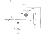
- a unidirectional filter portion 16 having filter performance in the direction A1 of supplying high pressure oil is provided.
- the accumulator 18 is installed downstream of the filter unit 16, so the supply pump 12 is stopped.
- the accumulator 18 is actuated to flow the oil into the high pressure oil passage 14 and also flow in the direction of the low pressure oil passage 20 (direction B1 shown in FIG. 3).
- This oil flow is in the reverse direction to the normal oil flow direction It becomes. For this reason, there is a possibility that a reverse pressure acts on the filter unit 16 and the mesh-like filter element provided in the filter unit 16 is broken.
- Patent Document 1 discloses a hydraulic device capable of supplying oil discharged from an oil supply pump to a high pressure oil passage and storing the pressure of the high pressure oil passage in an accumulator. .
- the configuration having the two systems of the high pressure oil passage and the low pressure oil passage as shown in FIG. 3 no mention is made of the prevention of breakage of the unidirectional filter part for high pressure oil.
- the present invention has been made in view of the above problems, and an object thereof is to provide a new and improved hydraulic device capable of preventing damage to a filter unit for high-pressure oil and a prime mover provided with the hydraulic device. Do.
- an accumulator capable of supplying oil from an oil tank to a high pressure oil passage and a low pressure oil passage via a supply pump, and storing the oil pressure of the oil supplied from the supply pump to the high pressure oil passage It is a hydraulic device provided, The filter part provided along the direction which supplies the above-mentioned oil between the connection point with the accumulator of the above-mentioned high pressure oil way, and the above-mentioned supply pump, The above-mentioned filter part and the above-mentioned connection point And a non-return valve capable of preventing reverse flow of the oil to the filter portion.
- the check valve capable of preventing the backflow of oil to the filter unit is provided between the filter unit and the connection point between the high pressure oil passage and the accumulator. It is possible to prevent the oil from flowing backward in the direction of the filter and damaging the filter.
- the filter unit includes an introduction unit for introducing the oil supplied from the supply pump, and a mesh-like filter element capable of filtering the oil introduced from the introduction unit.
- a filter core made of a substantially cylindrical hard material in which a coarse filter hole having a mesh size larger than the mesh of the filter element is formed in the wall, and the wall is encased in the filter element; And a discharge part capable of discharging the oil filtered by the filter element.
- the high pressure oil passage is provided with a high pressure side relief valve which is opened when the hydraulic pressure of the high pressure oil passage is equal to or more than a predetermined value.
- a low pressure side relief valve may be provided which is opened when the oil pressure in the oil passage is equal to or more than a predetermined value, and the high pressure side relief valve and the low pressure side relief valve may be connected to the oil tank on the relief side.
- the other aspect of this invention is a motive power apparatus, Comprising:
- the control apparatus by which the hydraulic device in any one of the above-mentioned is provided is characterized by the above-mentioned.
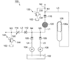
- FIG. 1 is a schematic block diagram of an embodiment of the hydraulic device of the present invention.
- the hydraulic system 100 is a hydraulic system capable of supplying oil to the high pressure oil path L1 and the low pressure oil path L2 by the common oil tank 102 and the supply pump 104. Further, in the present embodiment, the hydraulic device 100 has the high pressure oil passage L1 and the low pressure oil passage L2, and prevents the backflow to the filter portion 120 provided in the high pressure oil passage L1 to prevent the filter portion 120 from being damaged. A check valve 110 is provided for this purpose.
- the hydraulic device 100 is a servomotor or control device used in gas turbines, steam turbines, and other various types of prime movers (priming devices), and hydraulic pressure is used as hydraulic oil in hydraulic control of a device in which hydraulic control is performed.
- Supply high pressure oil of about 10 kg / cm2. That is, high-pressure oil serving as hydraulic oil to be used in hydraulic control of a servomotor, a control device, etc. is supplied from the oil tank 102 through the oil passage L4 having the check valve (check valve) 105 interposed by the supply pump 104.
- the high pressure oil is supplied to the high pressure oil passage L1 (high pressure oil system).
- the check valve 105 is a one-way valve that opens when pressure oil flows from the supply pump 104 toward the oil passage L1, and closes so as to prevent the flow of pressure oil in the opposite direction.
- a spare pump 108 is provided as a substitute pump when the supply pump 104 has a failure or the like.
- the spare pump 108 as a substitute pump for the high pressure oil path from the oil tank 102 through the oil path L5 in which the check valve (check valve) 109 is interposed.
- the high pressure oil can be supplied to L1 (high pressure oil system).
- An accumulator 106 capable of storing the oil pressure of the oil supplied from the supply pump 102 is connected to the high pressure oil passage L1.
- the accumulator 106 is, as conventionally known, formed by fluid-tightly dividing the pressure accumulation chamber and the back pressure chamber by a piston or an elastic expansion member, and when the pressure in the pressure accumulation chamber exceeds the pressure in the back pressure chamber, The movement of the piston and the expansion of the elastic expansion body enlarge the volume of the pressure accumulation chamber, and the hydraulic pressure is stored in the pressure accumulation chamber. Therefore, by controlling the pressure in the back pressure chamber, it is possible to adjust the set minimum pressure at which the pressure is stored in the pressure accumulation chamber.
- the accumulator 106 can store an oil pressure of about 8 kg / cm 2.
- the high pressure oil passage L1 is provided with a high pressure side relief valve 130 which is opened when the hydraulic pressure of the high pressure oil passage L1 is equal to or more than a predetermined value.
- the high pressure side relief valve 130 has a valve body 132 which opens and closes a port in the same manner as conventionally known, and a spring 134 which provides a force for pressing the valve body 132 against a valve seat (not shown). There is.
- the valve body 132 when the hydraulic pressure in the high pressure oil passage L1 is less than the predetermined pressure, the valve body 132 is pressed against the valve seat to close the port, and when the hydraulic pressure in the high pressure oil passage L1 is greater than the predetermined pressure The valve body 132 is moved against the force of the spring 134, the port is opened, and the pressure oil in the high pressure oil passage L1 is drained to the oil tank 102.
- the function of the high pressure side relief valve 130 can prevent the hydraulic pressure of the high pressure oil passage L1 from becoming equal to or higher than a predetermined pressure.
- the high pressure side relief valve 130 is set such that the hydraulic pressure of the high pressure oil passage L1 does not reach 10 kg / cm 2 or more.
- the hydraulic device 100 is used as a low pressure for lubricating oil such as a bearing of a turbine.
- a low pressure oil passage L2 (bearing oil system) for supplying oil is provided. That is, the low pressure oil is supplied from the oil tank 102 to the low pressure oil passage L2 via the oil passage L4 with the check valve (check valve) 105 interposed by the supply pump 104.
- the low pressure oil passage L2 is opened as oil flows from the supply pump 104 toward the low pressure oil passage L2 on the inlet side, and is a one-way valve closed so as to prevent the flow of pressurized oil in the opposite direction.
- a valve 112 is provided.
- an oil pressure adjusting valve 114 is provided which adjusts the oil pressure of the oil to a predetermined pressure or less.
- the hydraulic pressure adjustment valve 114 adjusts the hydraulic pressure of the low pressure oil passage L2 to 1.2 kg / cm2.
- the low pressure oil passage L2 is provided with a low pressure side relief valve 140 which is opened when the hydraulic pressure of the low pressure oil passage L2 is equal to or more than a predetermined value.
- the low pressure side relief valve 140 has a valve body 142 which opens and closes a port in the same manner as known in the prior art, and a spring 144 which applies a force to press the valve body 142 against a valve seat (not shown). .
- the low pressure side relief valve 140 is set so that the hydraulic pressure in the low pressure oil passage L2 does not exceed 1.2 kg / cm 2, and when the hydraulic pressure in the low pressure oil passage L 2 is 1.2 kg / cm 2 or more, the valve body 142 is moved against the force of the spring 144, the port is opened, and the pressure oil in the low pressure oil passage L2 is drained to the oil tank 102.
- the filter unit 120 is a unidirectional filter device provided between a connection point N1 of the high pressure oil passage L1 with the accumulator 106 and the supply pump 104 and having a filter function in the direction of supplying oil to the high pressure oil passage L1. is there. The details of the configuration of the filter unit 120 will be described later.
- the check valve 110 capable of preventing the backflow of oil to the filter unit 120 is provided. It features. That is, the high pressure oil is prevented from flowing backward in the direction opposite to the forward direction from the supply pump 104 toward the high pressure oil passage L1, thereby preventing the filter portion 120 from being damaged.
- a spare pump 108 is further provided as an alternative pump when the supply pump 104 as the main oil pump fails.
- the hydraulic device 100 can supply the oil discharged from the supply pump 104 to both the high pressure oil passage L1 and the low pressure oil passage L2, and when the supply pump 104 is stopped, etc.
- An accumulator 106 capable of storing pressure is provided.
- the filter unit (high pressure oil filter) 120 has a risk that the rubber balloon-like puddle 106a in the accumulator 106 is damaged by foreign matter in the oil discharged from the supply pump 104. It needs to be installed in between.
- the high-pressure oil discharged from the supply pump 104 which is the main oil pump, is used for the high-pressure oil system L1 and the bearing system L2, etc.
- the high-pressure oil system L1 has a pressure of 10 kg / cm 2 and the bearing oil system L2 has 1 The pressure is .2 kg / cm2.
- the check valve 110 is not provided downstream of the filter unit 120, the accumulator 106 is operated to prevent a drop in high hydraulic pressure when the supply pump 104 and the spare pump 109 are switched. Then, oil flows from the connection point N1 not only to the high pressure oil system L1 but also from the high pressure oil system L1 to the low pressure oil passage L2 through the check valve 112 (back flow), and the unidirectional filter function There is a risk of damaging the filter section having Therefore, by installing the check valve 110 on the outlet side of the filter unit 120 which is to be a high pressure oil filter, backflow of oil from the high pressure oil system L1 to the low pressure oil passage L2 is prevented, and damage to the filter unit 120 is prevented. I
- the supply pump 104 is stopped as described above. There is a risk that the oil may reverse in the opposite direction to the forward direction in which the filter performance of the filter unit 120 is present. Therefore, by providing the check valve 110 on the downstream side of the filter portion 120 provided in the high pressure oil passage L1 and preventing backflow to the filter portion 120, damage to the filter portion can be prevented.
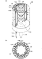
- FIG. 2 is a schematic configuration view of a filter unit provided in an embodiment of the hydraulic device of the present invention.
- the filter unit 120 provided in the hydraulic device 100 of the present embodiment has a fine mesh filter element 124 and a filter core 126 in a substantially cylindrical casing 123. It is provided.
- the filter element 124 is formed of a soft non-woven fabric or the like having a fine mesh 124a of about 0.025 microns, and as shown in FIG. 2A, the periphery of the filter core 126 is used to make the filter function dense. Are provided in a zigzag manner. Further, as shown in FIG. 2B, the filter element 124 is provided with a mesh-like support portion 129 formed of a hard material such as plastic for supporting the filter element 126 inside thereof.
- the filter core portion 126 is a substantially cylindrical member formed of a hard material such as aluminum, stainless steel, or a metal including a sintered material, and a filter hole coarser than the mesh 124 a of the filter element 124 is formed on the wall surface 126 a.
- a plurality of 128 are formed. That is, in the filter section 120, a mesh-like filter element 126 is attached to the outside of the filter support section 126 provided with the coarse filter holes 128, and a device having unidirectional filter performance from the outside to the inside It has become.
- the filter part 120 By making the filter part 120 into such a configuration, the high pressure oil introduced from the introduction port 122 of the high pressure oil introduction part 121 is introduced with the clearance part 125 between the casing 123 and the filter element 124 as a passage. Then, as shown in FIGS. 2A and 2B, high-pressure oil filtering is performed from the filter element 124 provided outside to the filter core part 126 provided inside. Further, when filtering in the forward direction, since the soft filter element 126 is supported by the support portion 129, the filter element 126 is neither stretched nor damaged.
- the inner side of the filter core portion 126 is an oil passage 127, and a discharge portion 130 capable of discharging the oil filtered by the filter element 124 is provided on the lower side, and the high pressure oil passage L1 is provided via the discharge pipe 132.
- the filtered oil is discharged. That is, in the present embodiment, the filter unit 120 is a unidirectional filter device having a filter function from the outside of the filter element 124 toward the inside of the filter core 126.
- the filter element of soft material is contracted in zigzag. There is a risk that 126 will swell and break. Also, even if the filter element 126 is not broken, there is a risk that the filter element 126 is expanded like a balloon to enlarge the mesh 124 a of the filter element 126 and degrade the filter performance thereafter.
- the check valve 110 is provided. As described above, the check valve 110 is provided to prevent the filter element 126 of the filter unit 120 from being damaged or deteriorated in function, so that the filter function of the high pressure oil side filter unit 120 can be maintained. Moreover, the reliability of the plant provided with the prime mover provided with the said control apparatus etc. can also be improved by preventing foreign material mixing to a servomotor, a control apparatus, etc. FIG.
Priority Applications (4)
| Application Number | Priority Date | Filing Date | Title |
|---|---|---|---|
| US14/770,162 US9797418B2 (en) | 2013-03-28 | 2013-08-27 | Hydraulic device and prime mover device |
| EP13880140.2A EP2980419B1 (en) | 2013-03-28 | 2013-08-27 | Hydraulic device and prime mover device |
| CN201380073150.9A CN104995413B (zh) | 2013-03-28 | 2013-08-27 | 液压装置及原动装置 |
| KR1020157022379A KR101773273B1 (ko) | 2013-03-28 | 2013-08-27 | 유압 장치 및 원동 장치 |
Applications Claiming Priority (2)
| Application Number | Priority Date | Filing Date | Title |
|---|---|---|---|
| JP2013-069515 | 2013-03-28 | ||
| JP2013069515A JP6177562B2 (ja) | 2013-03-28 | 2013-03-28 | 油圧装置及び原動装置 |
Publications (1)
| Publication Number | Publication Date |
|---|---|
| WO2014155767A1 true WO2014155767A1 (ja) | 2014-10-02 |
Family
ID=51622810
Family Applications (1)
| Application Number | Title | Priority Date | Filing Date |
|---|---|---|---|
| PCT/JP2013/072863 WO2014155767A1 (ja) | 2013-03-28 | 2013-08-27 | 油圧装置及び原動装置 |
Country Status (6)
| Country | Link |
|---|---|
| US (1) | US9797418B2 (ko) |
| EP (1) | EP2980419B1 (ko) |
| JP (1) | JP6177562B2 (ko) |
| KR (1) | KR101773273B1 (ko) |
| CN (1) | CN104995413B (ko) |
| WO (1) | WO2014155767A1 (ko) |
Cited By (1)
| Publication number | Priority date | Publication date | Assignee | Title |
|---|---|---|---|---|
| CN114109943A (zh) * | 2021-12-08 | 2022-03-01 | 中冶南方工程技术有限公司 | 转炉二文喉口液压伺服系统 |
Families Citing this family (22)
| Publication number | Priority date | Publication date | Assignee | Title |
|---|---|---|---|---|
| CN105020207B (zh) * | 2015-06-16 | 2017-05-31 | 中国海洋石油总公司 | 具有紧急泄压的双冗余调压装置 |
| CN105889212A (zh) * | 2016-05-12 | 2016-08-24 | 浙江工业职业技术学院 | 一种采用全频段工况自适应滤波、起电和离心的滤油器 |
| CN105889211A (zh) * | 2016-05-12 | 2016-08-24 | 浙江工业职业技术学院 | 采用全频段滤波、起电、分离、吸附和离心的滤油方法 |
| CN105937519A (zh) * | 2016-05-12 | 2016-09-14 | 王雅莉 | 一种采用滤波器、起电、分离和吸附的滤油方法 |
| CN105864198A (zh) * | 2016-05-12 | 2016-08-17 | 陈连萍 | 用变结构工况自适应滤波、磁化、磁场和离心的过滤方法 |
| CN105840592A (zh) * | 2016-05-12 | 2016-08-10 | 陈连萍 | 用工况自适应滤波、磁化、旋转磁场和离心的过滤方法 |
| CN105864170A (zh) * | 2016-05-12 | 2016-08-17 | 王雅莉 | 一种采用变结构滤波、起电、分离和吸附的滤油方法 |
| CN105909610A (zh) * | 2016-05-12 | 2016-08-31 | 李�昊 | 用全频段滤波、起电、分离、吸附和旋转磁场的滤油方法 |
| CN105736523A (zh) * | 2016-05-12 | 2016-07-06 | 徐燚超 | 用全频段滤波、磁化、吸附、旋转磁场和离心的滤油方法 |
| CN105782168A (zh) * | 2016-05-12 | 2016-07-20 | 徐燚超 | 一种采用抑波、磁化、吸附、旋转磁场和离心的过滤方法 |
| CN105864224A (zh) * | 2016-05-12 | 2016-08-17 | 王雅莉 | 用变结构工况自适应滤波、起电、分离和吸附的过滤方法 |
| CN105889209A (zh) * | 2016-05-12 | 2016-08-24 | 浙江工业职业技术学院 | 一种用全频段变结构滤波、起电、分离和离心的过滤箱 |
| CN105971991A (zh) * | 2016-05-12 | 2016-09-28 | 王雅莉 | 一种采用滤波器、磁化、吸附和旋转磁场的过滤方法 |
| CN105864181A (zh) * | 2016-05-12 | 2016-08-17 | 绍兴文理学院 | 一种采用抑波、磁化和吸附的过滤方法 |
| CN105889213A (zh) * | 2016-05-12 | 2016-08-24 | 浙江工业职业技术学院 | 一种用全频段变结构滤波、起电、分离和离心的过滤方法 |
| CN105864197A (zh) * | 2016-05-12 | 2016-08-17 | 谢阿招 | 用变结构工况自适应滤波、磁化、磁场和离心的过滤器 |
| CN105889194A (zh) * | 2016-05-12 | 2016-08-24 | 张华芳 | 用起电、分离、电控环吸附和旋转磁场处理液压油的方法 |
| CN105909605A (zh) * | 2016-05-12 | 2016-08-31 | 李�昊 | 用变结构工况自适应滤波、起电和旋转磁场的过滤方法 |
| CN105889216A (zh) * | 2016-05-12 | 2016-08-24 | 王雅莉 | 用全频段变结构工况自适应滤波、吸附和磁场的过滤方法 |
| CN105864212A (zh) * | 2016-05-12 | 2016-08-17 | 王雅莉 | 一种采用抑波、磁化、吸附和旋转磁场的过滤方法 |
| CN105864176A (zh) * | 2016-05-12 | 2016-08-17 | 王雅莉 | 用全频段工况自适应滤波、吸附和旋转磁场的滤油方法 |
| US11708684B2 (en) | 2019-11-06 | 2023-07-25 | Caterpillar Inc. | Hydraulic tank |
Citations (7)
| Publication number | Priority date | Publication date | Assignee | Title |
|---|---|---|---|---|
| JPS50145778A (ko) * | 1974-05-16 | 1975-11-22 | ||
| JPH03128406U (ko) * | 1990-04-10 | 1991-12-25 | ||
| JPH1054215A (ja) * | 1996-08-14 | 1998-02-24 | Nippon Soken Inc | 内燃機関の潤滑回路における油圧制御装置 |
| JPH10328507A (ja) * | 1997-05-29 | 1998-12-15 | Wako Sangyo Kk | 流体フィルタ |
| JP2004156537A (ja) | 2002-11-07 | 2004-06-03 | Nissan Motor Co Ltd | 内燃機関の圧縮比制御装置 |
| JP2004346769A (ja) * | 2003-05-20 | 2004-12-09 | Toyota Motor Corp | 油圧装置 |
| JP2012229802A (ja) * | 2011-04-20 | 2012-11-22 | Jc Bamford Excavators Ltd | 流体回路およびこの流体回路を含む作業機械 |
Family Cites Families (16)
| Publication number | Priority date | Publication date | Assignee | Title |
|---|---|---|---|---|
| JPS5637701U (ko) * | 1979-08-31 | 1981-04-10 | ||
| JPS5637701A (en) | 1979-09-04 | 1981-04-11 | Mitsubishi Electric Corp | Retrodirective array antenna |
| JPS63171703A (ja) | 1987-01-09 | 1988-07-15 | Hitachi Ltd | 物品管理方式 |
| JPS63171703U (ko) * | 1987-04-30 | 1988-11-08 | ||
| KR100186911B1 (ko) * | 1995-04-13 | 1999-03-20 | 구종철 | 오일필터를 이용한 내연기관의 엔진오일, 필터 교환시기 경고장치 |
| JPH09122999A (ja) | 1995-11-07 | 1997-05-13 | Amada Co Ltd | 二重シリンダー駆動用油圧回路 |
| US6814409B2 (en) * | 2001-04-12 | 2004-11-09 | A-Dec, Inc. | Hydraulic drive system |
| US7290389B2 (en) * | 2003-07-22 | 2007-11-06 | Eaton Corporation | Hydraulic drive system and improved filter sub-system therefor |
| JP4385752B2 (ja) * | 2003-12-10 | 2009-12-16 | トヨタ自動車株式会社 | 変速機の潤滑装置 |
| CN2898092Y (zh) | 2006-03-10 | 2007-05-09 | 山东晨钟机械股份有限公司 | 盘式热分散机 |
| DE102006042372A1 (de) * | 2006-09-08 | 2008-03-27 | Deere & Company, Moline | Ladegerät |
| DE102008038520A1 (de) * | 2008-08-20 | 2010-02-25 | Robert Bosch Gmbh | Vorrichtung zum Bereitstellen eines Drucks für einen hydraulischen Verbraucher und Verfahren zum Bereitstellen eines Drucks |
| CN102032121B (zh) | 2009-09-25 | 2012-12-26 | 上海汇益控制系统股份有限公司 | 兆瓦级风机的液压制动系统 |
| CN101983835A (zh) | 2010-11-04 | 2011-03-09 | 路文忠 | 由密封件密封使液压油在封闭油路中循环的直线静压导轨 |
| CN202733127U (zh) | 2012-07-13 | 2013-02-13 | 中国舰船研究设计中心 | 一种船用液动阀门启闭控制液压系统 |
| CN102962232B (zh) | 2012-11-23 | 2015-12-23 | 武汉华液传动制造有限公司 | 高压脉冲紊流管道冲洗系统 |
-
2013
- 2013-03-28 JP JP2013069515A patent/JP6177562B2/ja not_active Expired - Fee Related
- 2013-08-27 CN CN201380073150.9A patent/CN104995413B/zh active Active
- 2013-08-27 KR KR1020157022379A patent/KR101773273B1/ko active IP Right Grant
- 2013-08-27 EP EP13880140.2A patent/EP2980419B1/en active Active
- 2013-08-27 WO PCT/JP2013/072863 patent/WO2014155767A1/ja active Application Filing
- 2013-08-27 US US14/770,162 patent/US9797418B2/en active Active
Patent Citations (7)
| Publication number | Priority date | Publication date | Assignee | Title |
|---|---|---|---|---|
| JPS50145778A (ko) * | 1974-05-16 | 1975-11-22 | ||
| JPH03128406U (ko) * | 1990-04-10 | 1991-12-25 | ||
| JPH1054215A (ja) * | 1996-08-14 | 1998-02-24 | Nippon Soken Inc | 内燃機関の潤滑回路における油圧制御装置 |
| JPH10328507A (ja) * | 1997-05-29 | 1998-12-15 | Wako Sangyo Kk | 流体フィルタ |
| JP2004156537A (ja) | 2002-11-07 | 2004-06-03 | Nissan Motor Co Ltd | 内燃機関の圧縮比制御装置 |
| JP2004346769A (ja) * | 2003-05-20 | 2004-12-09 | Toyota Motor Corp | 油圧装置 |
| JP2012229802A (ja) * | 2011-04-20 | 2012-11-22 | Jc Bamford Excavators Ltd | 流体回路およびこの流体回路を含む作業機械 |
Non-Patent Citations (1)
| Title |
|---|
| See also references of EP2980419A4 |
Cited By (2)
| Publication number | Priority date | Publication date | Assignee | Title |
|---|---|---|---|---|
| CN114109943A (zh) * | 2021-12-08 | 2022-03-01 | 中冶南方工程技术有限公司 | 转炉二文喉口液压伺服系统 |
| CN114109943B (zh) * | 2021-12-08 | 2023-05-26 | 中冶南方工程技术有限公司 | 转炉二文喉口液压伺服系统 |
Also Published As
| Publication number | Publication date |
|---|---|
| KR20150108895A (ko) | 2015-09-30 |
| CN104995413A (zh) | 2015-10-21 |
| US9797418B2 (en) | 2017-10-24 |
| EP2980419A1 (en) | 2016-02-03 |
| US20160010669A1 (en) | 2016-01-14 |
| EP2980419B1 (en) | 2021-10-20 |
| EP2980419A4 (en) | 2016-11-23 |
| CN104995413B (zh) | 2017-11-21 |
| JP6177562B2 (ja) | 2017-08-09 |
| JP2014190524A (ja) | 2014-10-06 |
| KR101773273B1 (ko) | 2017-08-31 |
Similar Documents
| Publication | Publication Date | Title |
|---|---|---|
| WO2014155767A1 (ja) | 油圧装置及び原動装置 | |
| JP2014190524A5 (ko) | ||
| EP3351847A1 (en) | Water piping system and control method therefor | |
| US10018235B2 (en) | Hydraulic supply apparatus | |
| RU2008130362A (ru) | Гидростатический привод | |
| EP2741960B1 (en) | Pressure supply system for a fresh water system of an aircraft | |
| JP5677866B2 (ja) | 産業用車両の油圧ポンプ制御システムと産業用車両 | |
| WO2011116285A2 (en) | Pressure relief apparatus for hydropneumatic vessel | |
| JP6609550B2 (ja) | オイルセパレータ及び車両用油分分離システム | |
| JP6375415B2 (ja) | 高圧洗浄装置及び高圧洗浄車 | |
| JP2010216619A (ja) | 油圧回路 | |
| KR20160141730A (ko) | 댐핑 장치 및 슬립 제어 가능한 차량 브레이크 시스템 | |
| JP2013108622A (ja) | 工作機械及びモータポンプユニット | |
| JP2012130827A (ja) | 濾過精度可変型フィルタ | |
| CN105121030B (zh) | 卸压模块 | |
| JP2020511608A (ja) | 燃料噴射システム用のバルブ配列、並びに、燃料噴射システム | |
| KR101723398B1 (ko) | 브레이크 시스템 | |
| JP6157871B2 (ja) | 高圧洗浄装置及び高圧洗浄車 | |
| JP5782483B2 (ja) | 油圧ユニット及び油圧システム | |
| CN214889527U (zh) | 管道组件及水处理设备 | |
| JP2018040313A (ja) | 燃料噴射装置 | |
| JPH1073103A (ja) | 大流量アクチュエータを備えた油圧回路 | |
| KR20060084626A (ko) | 오리피스 릴리프 밸브 및 이를 구비하는 유압 공급 시스템 | |
| JP2009115221A (ja) | 油圧機器における脈動軽減装置 | |
| KR20180073142A (ko) | 차량 유압시스템의 축압기 피크 압력 저감 장치 및 그것을 포함하는 차량의 유압시스템 |
Legal Events
| Date | Code | Title | Description |
|---|---|---|---|
| 121 | Ep: the epo has been informed by wipo that ep was designated in this application |
Ref document number: 13880140 Country of ref document: EP Kind code of ref document: A1 |
|
| WWE | Wipo information: entry into national phase |
Ref document number: 2013880140 Country of ref document: EP |
|
| ENP | Entry into the national phase |
Ref document number: 20157022379 Country of ref document: KR Kind code of ref document: A |
|
| WWE | Wipo information: entry into national phase |
Ref document number: 14770162 Country of ref document: US |
|
| NENP | Non-entry into the national phase |
Ref country code: DE |