WO2014155579A1 - 多弁型蒸気弁及び蒸気タービン - Google Patents
多弁型蒸気弁及び蒸気タービン Download PDFInfo
- Publication number
- WO2014155579A1 WO2014155579A1 PCT/JP2013/059077 JP2013059077W WO2014155579A1 WO 2014155579 A1 WO2014155579 A1 WO 2014155579A1 JP 2013059077 W JP2013059077 W JP 2013059077W WO 2014155579 A1 WO2014155579 A1 WO 2014155579A1
- Authority
- WO
- WIPO (PCT)
- Prior art keywords
- valve
- steam
- regulating
- pilot
- flow path
- Prior art date
- Legal status (The legal status is an assumption and is not a legal conclusion. Google has not performed a legal analysis and makes no representation as to the accuracy of the status listed.)
- Ceased
Links
Images





Classifications
-
- F—MECHANICAL ENGINEERING; LIGHTING; HEATING; WEAPONS; BLASTING
- F01—MACHINES OR ENGINES IN GENERAL; ENGINE PLANTS IN GENERAL; STEAM ENGINES
- F01K—STEAM ENGINE PLANTS; STEAM ACCUMULATORS; ENGINE PLANTS NOT OTHERWISE PROVIDED FOR; ENGINES USING SPECIAL WORKING FLUIDS OR CYCLES
- F01K13/00—General layout or general methods of operation of complete plants
- F01K13/02—Controlling, e.g. stopping or starting
-
- F—MECHANICAL ENGINEERING; LIGHTING; HEATING; WEAPONS; BLASTING
- F01—MACHINES OR ENGINES IN GENERAL; ENGINE PLANTS IN GENERAL; STEAM ENGINES
- F01D—NON-POSITIVE DISPLACEMENT MACHINES OR ENGINES, e.g. STEAM TURBINES
- F01D17/00—Regulating or controlling by varying flow
- F01D17/10—Final actuators
- F01D17/12—Final actuators arranged in stator parts
- F01D17/18—Final actuators arranged in stator parts varying effective number of nozzles or guide conduits, e.g. sequentially operable valves for steam turbines
-
- F—MECHANICAL ENGINEERING; LIGHTING; HEATING; WEAPONS; BLASTING
- F16—ENGINEERING ELEMENTS AND UNITS; GENERAL MEASURES FOR PRODUCING AND MAINTAINING EFFECTIVE FUNCTIONING OF MACHINES OR INSTALLATIONS; THERMAL INSULATION IN GENERAL
- F16K—VALVES; TAPS; COCKS; ACTUATING-FLOATS; DEVICES FOR VENTING OR AERATING
- F16K1/00—Lift valves or globe valves, i.e. cut-off apparatus with closure members having at least a component of their opening and closing motion perpendicular to the closing faces
- F16K1/32—Details
- F16K1/52—Means for additional adjustment of the rate of flow
-
- F—MECHANICAL ENGINEERING; LIGHTING; HEATING; WEAPONS; BLASTING
- F16—ENGINEERING ELEMENTS AND UNITS; GENERAL MEASURES FOR PRODUCING AND MAINTAINING EFFECTIVE FUNCTIONING OF MACHINES OR INSTALLATIONS; THERMAL INSULATION IN GENERAL
- F16K—VALVES; TAPS; COCKS; ACTUATING-FLOATS; DEVICES FOR VENTING OR AERATING
- F16K31/00—Actuating devices; Operating means; Releasing devices
- F16K31/44—Mechanical actuating means
- F16K31/52—Mechanical actuating means with crank, eccentric, or cam
- F16K31/524—Mechanical actuating means with crank, eccentric, or cam with a cam
- F16K31/52408—Mechanical actuating means with crank, eccentric, or cam with a cam comprising a lift valve
-
- F—MECHANICAL ENGINEERING; LIGHTING; HEATING; WEAPONS; BLASTING
- F05—INDEXING SCHEMES RELATING TO ENGINES OR PUMPS IN VARIOUS SUBCLASSES OF CLASSES F01-F04
- F05D—INDEXING SCHEME FOR ASPECTS RELATING TO NON-POSITIVE-DISPLACEMENT MACHINES OR ENGINES, GAS-TURBINES OR JET-PROPULSION PLANTS
- F05D2220/00—Application
- F05D2220/30—Application in turbines
- F05D2220/31—Application in turbines in steam turbines
Definitions
- the present invention relates to a multi-valve steam valve that adjusts the amount of steam that flows in, and a steam turbine.
- a multi-valve steam valve 106 having a plurality of regulating valves is used during the warm-up operation.
- the multi-valve steam valve 106 includes an inner bar 13 provided inside a steam chamber to which steam is supplied, and a plurality of regulating valves 14 attached to the inner bar 13. Then, when the support bar 17 operates the inner bar 13, the adjustment valve 14 is driven in the vertical direction.
- the plurality of regulating valves 14 are set so as to be sequentially opened by moving the inner bar 13 upward.
- FIG. 11 is a graph showing the relationship between the steam flow rate and the valve lift amount (valve lift). Numbers 1 to 5 in the graph indicate the first adjustment valve 14 to the fifth adjustment valve 14 in the lift amount. It shows which adjustment valve 14 is lifted.
- the conventional multi-valve steam valve as shown in FIG. 11, since the flow rate range R of the regulating valve 14 that is initially opened is wide, there is a problem in controllability during low-speed rotation in warm-up operation. There is. In particular, it is known that when only the turbine is operated, such as during a trial operation, the rotational inertia (GD2) of the rotor is small, so that speed control is difficult.
- GD2 rotational inertia
- the multi-valve steam valve of the present invention includes a plurality of regulating valves that gradually separate the valve body from the valve seat and widen the flow path by driving the valve shaft in one direction, and sequentially opening the plurality of regulating valves.
- the multi-valve steam valve that allows steam to flow in at least the regulating valve that is initially opened among the plurality of regulating valves is when driven in one direction from the closed state compared to the other regulating valves. It is comprised so that the inflow amount of steam may become small.
- the flow rate of steam from the fully closed state to the fully open state of the regulating valve that is initially opened decreases. That is, the controllability at the time of fine speed adjustment of the multi-valve steam valve is improved by narrowing the flow rate range of the regulating valve.
- the regulating valve that is opened at least first is formed such that the valve body is smaller than the valve body of the other regulating valve, and the inflow amount of steam is reduced. Is preferred.
- the regulating valve that is opened at least first is a space in which the valve body abuts the pilot valve connected to the valve shaft and the valve seat, and accommodates the pilot valve therein.
- a valve body main body formed with a steam introduction hole communicating with the space and the upstream flow path, and a steam discharge hole communicating with the space and the downstream flow path, and in a closed state
- the pilot valve closes the steam introduction hole and the steam discharge hole, and when the valve shaft is driven in one direction from the closed state, the steam introduction hole and the steam discharge hole are released to pass through the space.
- the upstream flow path and the downstream side may communicate with each other, and the pilot valve may lift the valve body away from the valve seat by driving the valve shaft in one direction.
- the adjusting valve is constituted by the main valve and the pilot valve, the pilot valve can be controlled.
- the flow range of the regulating valve relative to the valve lift can be narrowed, and the controllability at the time of fine speed adjustment of the multi-valve steam valve is improved.
- valve shaft of the valve body is passed from below to a valve shaft hole formed in an inner bar disposed in the flow path, and is disposed above the valve shaft through the inner bar. It is preferable that the formed enlarged diameter portion is lifted to allow the steam to flow by moving the valve body forward and backward with respect to the valve seat.
- the speed can be easily adjusted even at a low rotational speed.
- the multi-valve steam valve includes a connecting arm that is disposed outside the flow path and has a plurality of cams that drive the valve shafts of the plurality of regulating valves, and the steam is generated by rotating the connecting arm. It is good also as a structure made to flow in.
- the present invention also provides a steam turbine including the multi-valve steam valve described in any of the steams.
- the flow rate of steam from the fully closed state to the fully open state of the regulating valve that is initially opened is reduced. That is, the controllability at the time of fine speed adjustment of the multi-valve steam valve is improved by narrowing the flow rate range of the regulating valve.
- a main steam header pipe 2 that supplies steam to the steam turbine 1 is connected to a turbine body 3 of the steam turbine 1 via a steam supply passage 4.
- the steam supply passage 4 is provided with a stop valve 5 and a multi-valve steam valve 6 that is a steam control valve, and the steam supply to the turbine body 3 is shut off by fully closing the stop valve 5 or the steam supply flow rate. Is controlled by a multi-valve steam valve 6.
- the rotor of the steam turbine 1 transmits rotational energy to a machine such as a generator 7 (or a compressor).
- the steam turbine 1 is controlled by a governor 8 (control device).
- the governor 8 is a computing device that controls the steam turbine 1. For example, the rotational speed of the turbine rotor is input using the speed detector 9, and the multi-valve steam valve 6 is controlled based on this rotational speed. It is configured.
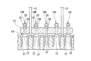
- the multi-valve steam valve 6 is attached to the casing 11 in which a steam chamber 12 to which steam is supplied is formed, an inner bar 13 disposed inside the steam chamber 12, and the inner bar 13.
- Such a multi-valve steam valve 6 is also called an inner bar valve because an inner bar is used to support the regulating valve.
- the steam chamber 12 is a space having a length in one direction.
- the steam supply passage 4 that connects the steam chamber 12 and the steam turbine 1 is composed of a plurality (five in this embodiment) of steam passages 19.
- the upstream end of each steam passage 19 is disposed at a predetermined interval in the longitudinal direction of the steam chamber 12, and the valve body 15 of the regulating valve 14 is applied to the opening 20 on the steam chamber 12 side.
- the valve seat 21 which contacts is formed.
- each steam passage 19 is open to the casing 22 of the steam turbine 1.
- the opening 23 on the side of the passenger compartment 22 is arranged at a predetermined interval in the circumferential direction of the outer periphery of the passenger compartment 22.
- the outer periphery of the passenger compartment 22 is divided into five parts, and a steam passage 19 is connected to each part.
- the plurality of regulating valves 14 attached to the inner bar 13 include a valve body 15 that contacts the valve seat 21 and a valve shaft 16 that extends upward from the valve body 15. Yes.
- the inner bar 13 is a rod-like member that is supported by a support rod 17 whose opening degree is controlled by the governor 8 and has a length along the longitudinal direction of the steam chamber 12.
- the inner bar 13 is disposed above the valve seat 21 so as to follow the arrangement direction of the plurality of valve seats 21.
- the inner bar 13 has a valve shaft hole 24 through which the valve shaft 16 of the adjustment valve 14 is inserted.
- the regulating valve 14 is of a type in which the valve body 15 is gradually separated from the valve seat 21 to widen the flow path by driving the valve shaft 16 in one direction.
- a male screw groove is formed at least on the outer peripheral surface of the valve shaft 16, and a nut 25 is screwed together.
- the support bar 17 is a bar-shaped member extending upward from the inner bar 13 and can be operated in the vertical direction by a driving device such as an electro-hydraulic actuator (not shown).
- the multi-valve steam valve 6 configured as described above operates the support rod 17 to move the inner bar 13 in the vertical direction, thereby lifting the nut 25 and separating the valve body 15 of the adjustment valve 14 from the valve seat 21 (
- the steam in the steam chamber 12 is caused to flow into the casing 22 of the steam turbine 1 by advancing and retreating.
- the adjustment valve 14 can adjust the timing of separating from the valve seat 21 according to the position of the nut 25.
- the valve body 15 of the regulating valve 14 is driven by lifting the nut 25.
- the present invention is not limited to this. For example, it is good also as a structure which provides an enlarged diameter part above the valve shaft 16, and changes the position of an enlarged diameter part with each adjustment valve 14.
- the central first regulating valve 14A among the five regulating valves 14 is opened, and then the first regulating valve 14A located next to one of the first regulating valves 14A.
- the second regulating valve 14B opens, then the third regulating valve 14C next to the other of the first regulating valve 14A opens, then the fourth regulating valve 14D at one end opens, and finally the remaining fifth regulating valve 14E is set to open.
- the steam is configured to flow into the vehicle compartment 22 through the vehicle.
- the plurality of openings 20 are configured to have a maximum flow rate when all the regulating valves 14 are opened. Further, since the valve body 15 is pulled in the direction of the valve seat 21 by the steam force, the plurality of valve bodies 15 are sequentially seated on the valve seat 21 as the inner bar 13 moves up and down, and the valve body 15 is operated as planned. Opening and closing is performed.
- the plurality of regulating valves 14 of the present embodiment are shaped such that only the first regulating valve 14A is less inflow of steam until it is in the open state than the other regulating valves 14.
- the first adjustment valve 14A is smaller than the other adjustment valves 14, and the valve body 15 of the first adjustment valve 14A has a smaller outer shape than the other adjustment valves 14.
- the inner diameter of the valve seat 21 with which the valve body 15 of the first adjusting valve 14A abuts is also made small.
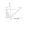
- FIG. 4 is a graph showing the relationship between the steam flow rate and the valve lift (valve lift).
- the numbers 1 to 5 in the graph indicate which regulating valve 14 is lifted from the first regulating valve 14A to the fifth regulating valve 14E at the lift amount.
- the steam flow rate R1 from the fully closed state to the fully opened state of the first regulating valve 14A decreases as shown in FIG. That is, the controllability at the time of fine speed adjustment of the multi-valve steam valve 6 is improved by narrowing the flow rate range of the first adjustment valve 14A.
- the driving force for operating the first adjustment valve 14A can be reduced. That is, since the thrust force of the steam applied to the valve body 15 is reduced by downsizing the valve body 15, the power for driving the valve body 15 can be reduced.
- the first adjustment valve 14A is a valve that opens first among the plurality of adjustment valves 14, the pressure difference between the steam chamber 12 and the vehicle compartment 22 is large, so that the effect of downsizing is high.
- the first adjustment valve 14 ⁇ / b> A is opened, steam flows into the casing 22 of the steam turbine 1, so that the pressure difference between the casing 22 and the steam chamber 12 becomes small. Thereby, when driving the other regulating valve 14, the driving force can be small.
- the multi-valve steam valve 6B of the present embodiment includes a casing 11B in which a plurality of (four in this embodiment) pipes 19B branched from the steam supply passage 4 are formed.
- a valve seat 21B provided in the pipe 19B, a plurality of regulating valves 26 provided corresponding to the valve seat 21B, and regulating valve drive mechanisms 27 for driving the regulating valves 26 are provided.
- Such a multi-valve steam valve is called an independent valve because it is driven not by an inner bar but by an independent support rod.
- the upstream end of the pipe 19B connecting the steam supply passage 4 and the vehicle compartment 22 is arranged at a predetermined interval in the extending direction of the steam supply passage 4, and is adjusted in the vicinity of the opening 20B.
- a valve seat 21B with which the valve body 32 of the valve 26 abuts is formed.
- each pipe 19 ⁇ / b> B is open to the casing 22 of the steam turbine 1.
- the opening 23 ⁇ / b> B on the side of the passenger compartment 22 is arranged at a predetermined interval in the circumferential direction of the outer periphery of the passenger compartment 22.
- the outer periphery of the passenger compartment 22 is divided into four parts, and a pipe 19B is connected to each part.
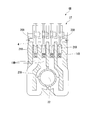
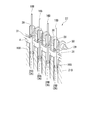
- the regulating valve drive mechanism 27 includes a plurality of valve chambers 28 that accommodate the valve shafts 16 of the respective regulating valves 14, and a connecting arm 29 that extends orthogonally to the plurality of valve chambers 28. And a cam lever 30 attached to a connecting arm 29 corresponding to the plurality of valve chambers 28.
- the connecting arm 29 is a rod-shaped member that can be controlled by the governor 8, and can be rotated by a driving device (not shown).
- the cam lever 30 and the valve shaft 16 ⁇ / b> B in the valve chamber 28 are connected by a connecting rod 31. The angle of the cam lever 30 is adjusted so that the adjusting valve 14 is opened in a predetermined order.
- the multi-valve steam valve 6 having the above-described configuration operates the connecting arm 29 to rotate the cam lever 30 to drive each valve shaft 16 ⁇ / b> B to transfer the steam in the steam supply passage 4 to the casing 22 of the steam turbine 1. It is configured to flow in.
- the connecting arm 29 by rotating the connecting arm 29, the first regulating valve 26A closer to the center among the four regulating valves 26 is opened first, and then the second regulating valve 26B from the other center is opened. Then, the third regulating valve 26C at one end is opened, and finally the remaining fourth regulating valve 26D is opened.
- the steam is configured to flow into the vehicle compartment 22 through the vehicle.
- the plurality of openings 20B are configured to have a maximum flow rate when all the regulating valves 26 are in an open state.
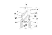
- the valve body 32 of the first adjustment valve 26A of the present embodiment includes a pilot valve 33 connected to the valve shaft 16B, a main valve 34 that is a valve body main body that contacts the valve seat 21B, have.
- the main valve 34 is a part forming the outer shape of the valve body 32, and has a valve seat abutting portion 35 that abuts the valve seat 21B.
- a pilot valve accommodating space 36 for accommodating the pilot valve 33 is formed inside the main valve 34.
- the valve seat abutting portion 35 of the main valve 34 is a circular region that seals the upstream side and the downstream side of the pipe 19 ⁇ / b> B by coming into contact with the valve seat 21.
- the main valve 34 is formed with a plurality of steam introduction holes 37 and steam discharge holes 38 that connect the pilot valve housing space 36 and the outside of the main valve 34.
- the steam introduction hole 37 and the steam discharge hole 38 communicate with each other through a pilot valve accommodation space 36.
- the steam introduction holes 37 are a plurality of holes that connect the pilot valve accommodation space 36 and the side surface of the main valve 34.
- the steam introduction hole 37 is formed on the outer surface of the main valve 34 on the upstream side of the valve seat contact portion 35.
- the steam discharge hole 38 is a hole that connects the pilot valve housing space 36 and the tip of the main valve 34.
- the steam discharge hole 38 is formed downstream of the valve seat contact portion 35 on the outer surface of the main valve 34.
- the pilot valve 33 is accommodated in the main valve 34 in a state in which the pilot valve 33 can move in the vertical direction in the pilot valve accommodation space 36 by driving the valve shaft 16B.
- the valve shaft 16 ⁇ / b> B extends above the main valve 34 through a valve shaft hole 39 formed in the main valve 34.
- the pilot valve 33 and the pilot valve housing space 36 seal the steam introduction hole 37 and the steam discharge hole 38 depending on their positions, or connect the steam introduction hole 37 and the steam discharge hole 38. It is formed so that it can communicate.
- the hole diameter of the steam introduction hole 37 and the steam discharge hole 38 and the number of the steam introduction holes 37 will be described.
- the hole diameter and the number of the steam introduction holes 37 are the same as those shown in FIG. It is appropriately set according to the amount of steam required in a state where steam flows only through the steam discharge hole 38.
- FIG. 9 is a graph showing the relationship between the steam flow rate and the valve lift (valve lift).
- the numbers 1 to 4 in the graph indicate which regulating valve 26 is lifted from the first regulating valve 26A to the fourth regulating valve 26D at the lift amount.
- the first adjustment valve 26A is constituted by the main valve 34 and the pilot valve 33, whereby the flow rate at the stage where the control by the pilot valve 33 is performed can be reduced, and the fine speed adjustment is performed. Becomes easier. That is, as shown in FIG. 9, control by the pilot valve 33 is possible. In the range R2 in which the control by the pilot valve 33 is performed, the flow rate range of the first adjustment valve 26A relative to the valve lift can be narrowed, and the controllability at the time of fine speed adjustment of the multi-valve steam valve 6B is improved. To do.
- valve body of the adjustment valve of the inner bar valve may be a valve body including the main valve and the pilot valve of the second embodiment.
- first adjustment valves 14A and 26A are configured to reduce the inflow amount of steam.
- present invention is not limited to this, and the other adjustment valves 14 and 26 are configured to have an inflow amount of steam. It is good also as a form which becomes small.
Landscapes
- Engineering & Computer Science (AREA)
- General Engineering & Computer Science (AREA)
- Mechanical Engineering (AREA)
- Chemical & Material Sciences (AREA)
- Combustion & Propulsion (AREA)
- Control Of Turbines (AREA)
- Lift Valve (AREA)
Abstract
Description
上記従来の多弁型蒸気弁においては、図11に示すように、最初に開状態となる調整弁14の流量範囲Rが広いため、暖機運転における低速回転時の制御性に難があるという問題がある。特に、試運転時などタービンのみを運転させる場合、ローターの回転慣性(GD2)が小さくなるため、調速が難しいことが知られている。
まず、本実施形態の多弁型蒸気弁6が適用される蒸気タービン1ついて説明する。図1に示すように、蒸気タービン1のタービン本体3には蒸気を蒸気タービン1に供給する主蒸気ヘッダ管2が蒸気供給通路4を介して接続されている。蒸気供給通路4には、止め弁5と蒸気加減弁である多弁型蒸気弁6が設けられており、タービン本体3への蒸気の供給を止め弁5の全閉により遮断、又は蒸気の供給流量を多弁型蒸気弁6によって制御するようになっている。
インナーバー13は、ガバナ8によって開度制御される支持棒17により支持され、蒸気室12の長手方向に沿う長さを有する棒状の部材である。インナーバー13は、複数の弁座21の配列方向に沿うように弁座21の上方に配置されている。インナーバー13には、調整弁14の弁軸16が挿通する弁軸孔24が穿設されている。
調整弁14は、一方向に弁軸16を駆動することにより徐々に弁体15が弁座21から離間して流路を広げる形式のものである。
支持棒17は、インナーバー13から上方に延在する棒形状の部材であり、図示しない電油アクチュエータなどの駆動装置によって上下方向に操作可能とされている。
なお、この実施形態ではナット25を吊り上げることによって調整弁14の弁体15を駆動する構成となっているが、これに限ることはない。例えば、弁軸16の上方に拡径部を設け、拡径部の位置を各々の調整弁14で変更する構成としてもよい。
また、弁体15は蒸気力によって弁座21の方向に引っ張られているので、インナーバー13の上下動に伴って、複数の弁体15が順次弁座21に着座して計画通りに弁の開閉が行われるようになっている。
なお、弁体15の大きさを変更することなく、対応する弁座21の内径を小さくすることによって第一調整弁14Aの蒸気の流入量を小さくするような構成としてもよい。
以下、本発明に係る第二実施形態の多弁型蒸気弁6Bを図面に基づいて説明する。なお、本実施形態では、上述した第一実施形態との相違点を中心に述べ、同様の部分についてはその説明を省略する。
図5及び図6に示すように、本実施形態の多弁型蒸気弁6Bは、蒸気供給通路4から分岐された複数(本実施形態では4本)の配管19Bが形成されたケーシング11Bと、各々の配管19Bに設けられた弁座21Bと、この弁座21Bに対応して設けられた複数の調整弁26と、各々の調整弁26を駆動する調整弁駆動機構27と、を有している。このような多弁型蒸気弁は、インナーバーではなく独立した支持棒にて駆動されることから独立弁と呼ばれている。
カムレバー30と弁室28内の弁軸16Bとは、連結棒31によって連結されている。カムレバー30の角度は、調整弁14が所定の順序で開状態となるように調整されている。
本実施形態では、コネクティングアーム29を回動させることによって、まず4つの調整弁26のうち、中央寄りの第一調整弁26Aが開き、次いで、もう一つの中央よりの第二調整弁26Bが開き、次いで、一方の端の第三調整弁26Cが開き、最後に、残りの第四調整弁26Dが開くように設定されている。即ち、まず、第一調整弁26Aが開くことによって、第一調整弁26Aによって閉鎖されていた開口部20Bを介して車室22に蒸気が流入し、出力が増大するに従い順次他の開口部20Bを介して車室22に蒸気が流入するように構成されている。複数の開口部20Bは、全ての調整弁26が開状態となった段階で、最大流量となるように構成されている。
蒸気導入孔37は、パイロット弁収容空間36と主弁34の側面とを接続する複数の孔である。蒸気導入孔37は、主弁34の外面において、弁座当接部35よりも上流側に形成されている。
蒸気排出孔38は、パイロット弁収容空間36と主弁34の先端とを接続する孔である。蒸気排出孔38は、主弁34の外面において、弁座当接部35よりも下流側に形成されている。
図8に示すように、パイロット弁33とパイロット弁収容空間36とは、その位置によって、蒸気導入孔37と蒸気排出孔38とを封止したり、蒸気導入孔37と蒸気排出孔38とを連通させたりすることができるように形成されている。
これにより、主弁34が弁座21Bより離間することにより流入する蒸気の量よりも少ない蒸気が蒸気供給通路4から配管19Bに流入する。
即ち、図9に示すように、パイロット弁33による制御が可能となる。パイロット弁33による制御が行われている範囲R2においては、弁リフトに対する第一調整弁26Aの流量範囲が狭くすることが可能になり、多弁型蒸気弁6Bの微速調整の際の制御性が向上する。
2 主蒸気ヘッダ管
3 タービン本体
4 蒸気供給通路
5 止め弁
6 多弁型蒸気弁
7 発電機(圧縮機)
8 ガバナ
9 速度検出器
11 ケーシング
12 蒸気室
13 インナーバー
14 調整弁
14A 第一調整弁
14B 第二調整弁
14C 第三調整弁
14D 第四調整弁
14E 第五調整弁
15 弁体
16 弁軸
17 支持棒
19 蒸気通路
20 開口部
21 弁座
22 車室
23 開口部
24 弁軸孔
25 ナット
26 調整弁
26A 第一調整弁
26B 第二調整弁
26C 第三調整弁
26D 第四調整弁
26E 第五調整弁
27 調整弁駆動機構
28 弁室
29 コネクティングアーム
30 カムレバー
31 連結棒
32 弁体
33 パイロット弁
34 主弁(弁体本体)
35 弁座当接部
36 パイロット弁収容空間
37 蒸気導入孔
38 蒸気排出孔
Claims (6)
- 一方向に弁軸を駆動することにより徐々に弁体が弁座から離間して流路を広げる調整弁を複数備え、該複数の調整弁を順次開状態とすることによって蒸気を流入させる多弁型蒸気弁において、
前記複数の調整弁のうち、少なくとも最初に開状態となる調整弁は、他の調整弁と比較して閉状態より一方向に駆動した際の蒸気の流入量が小さくなるように構成されている多弁型蒸気弁。 - 前記少なくとも最初に開状態となる調整弁は、前記弁体が他の調整弁の弁体よりも小型化され、蒸気の流入量が少なくなるように形成されている請求項1に記載の多弁型蒸気弁。
- 前記少なくとも最初に開状態となる調整弁は、
前記弁体が、
前記弁軸と接続されたパイロット弁と、
前記弁座と当接し、内部にパイロット弁を収容する空間と、前記空間と上流側の流路と連通する蒸気導入孔と、前記空間と下流側の流路と連通する蒸気排出孔と、が形成された弁体本体と、を有し、
閉状態においては、前記パイロット弁が前記蒸気導入孔及び蒸気排出孔を閉鎖し、
閉状態から前記弁軸を一方向に駆動することによって前記蒸気導入孔及び前記蒸気排出孔が解放されて前記空間を介して上流側の流路と下流側とが連通し、
さらに弁軸を一方向に駆動することによって前記パイロット弁が前記弁体を吊り上げて前記弁座から離間させる請求項1に記載の多弁型蒸気弁。 - 前記流路の内部に配置されたインナーバーに穿設した弁軸孔に下方から前記弁体の前記弁軸を通し、
前記インナーバーを介して前記弁軸の上方に形成した拡径部を吊り上げて前記弁体を前記弁座に対し進退させて蒸気を流入させる請求項1から請求項3のいずれか一項に記載の多弁型蒸気弁。 - 前記流路の外部に配置され、前記複数の調整弁の前記弁軸を駆動する複数のカムを有するコネクティングアームを有し、
前記コネクティングアームを回動させることにより蒸気を流入させる請求項1から請求項3のいずれか一項に記載の多弁型蒸気弁。 - 請求項1から請求項5のいずれか一項に記載の多弁型蒸気弁を備える蒸気タービン。
Priority Applications (5)
| Application Number | Priority Date | Filing Date | Title |
|---|---|---|---|
| PCT/JP2013/059077 WO2014155579A1 (ja) | 2013-03-27 | 2013-03-27 | 多弁型蒸気弁及び蒸気タービン |
| US14/770,351 US10227898B2 (en) | 2013-03-27 | 2013-03-27 | Multi-valve steam valve and steam turbine |
| CN201380073478.0A CN105074135B (zh) | 2013-03-27 | 2013-03-27 | 多阀型蒸汽阀及蒸汽涡轮 |
| JP2015507782A JP6089098B2 (ja) | 2013-03-27 | 2013-03-27 | 多弁型蒸気弁及び蒸気タービン |
| EP13879843.4A EP2952692A4 (en) | 2013-03-27 | 2013-03-27 | MULTISOUPAPES TYPE VAPOR VALVE AND STEAM TURBINE |
Applications Claiming Priority (1)
| Application Number | Priority Date | Filing Date | Title |
|---|---|---|---|
| PCT/JP2013/059077 WO2014155579A1 (ja) | 2013-03-27 | 2013-03-27 | 多弁型蒸気弁及び蒸気タービン |
Publications (1)
| Publication Number | Publication Date |
|---|---|
| WO2014155579A1 true WO2014155579A1 (ja) | 2014-10-02 |
Family
ID=51622656
Family Applications (1)
| Application Number | Title | Priority Date | Filing Date |
|---|---|---|---|
| PCT/JP2013/059077 Ceased WO2014155579A1 (ja) | 2013-03-27 | 2013-03-27 | 多弁型蒸気弁及び蒸気タービン |
Country Status (5)
| Country | Link |
|---|---|
| US (1) | US10227898B2 (ja) |
| EP (1) | EP2952692A4 (ja) |
| JP (1) | JP6089098B2 (ja) |
| CN (1) | CN105074135B (ja) |
| WO (1) | WO2014155579A1 (ja) |
Cited By (7)
| Publication number | Priority date | Publication date | Assignee | Title |
|---|---|---|---|---|
| JP2016176375A (ja) * | 2015-03-19 | 2016-10-06 | 三菱日立パワーシステムズ株式会社 | 蒸気弁装置、及び蒸気流制御システム、並びに蒸気タービン発電プラント |
| JP2016183608A (ja) * | 2015-03-26 | 2016-10-20 | 三菱日立パワーシステムズ株式会社 | 蒸気弁装置 |
| WO2017072880A1 (ja) * | 2015-10-28 | 2017-05-04 | 三菱重工コンプレッサ株式会社 | 弁装置、蒸気タービン設備 |
| JP2018168706A (ja) * | 2017-03-29 | 2018-11-01 | 三菱重工業株式会社 | 蒸気弁装置 |
| JP2019094928A (ja) * | 2017-11-17 | 2019-06-20 | 三菱重工コンプレッサ株式会社 | 弁装置及び蒸気タービン |
| EP3517740A1 (en) | 2018-01-30 | 2019-07-31 | Mitsubishi Heavy Industries Compressor Corporation | Valve device for turbine and method for producing valve device for a turbine |
| JP2020133586A (ja) * | 2019-02-25 | 2020-08-31 | 三菱重工コンプレッサ株式会社 | 弁装置及び蒸気タービン |
Families Citing this family (5)
| Publication number | Priority date | Publication date | Assignee | Title |
|---|---|---|---|---|
| JP6657250B2 (ja) * | 2015-04-03 | 2020-03-04 | ターボデン ソシエタ ペル アツィオーニTurboden Spa | 好ましくは有機ランキン・サイクルorcプラントのための多段タービン |
| US10827123B1 (en) | 2018-01-05 | 2020-11-03 | Gopro, Inc. | Modular image capture systems |
| JP2019214975A (ja) * | 2018-06-13 | 2019-12-19 | 株式会社東芝 | ボイラ給水ポンプ駆動用タービンの駆動システム |
| CN109882253A (zh) * | 2019-03-29 | 2019-06-14 | 中国船舶重工集团公司第七0四研究所 | 低噪声调节阀结构 |
| CN112360579A (zh) * | 2020-11-12 | 2021-02-12 | 中国长江动力集团有限公司 | 一种新型中间抽汽调节汽阀及连杆结构 |
Citations (13)
| Publication number | Priority date | Publication date | Assignee | Title |
|---|---|---|---|---|
| JPS51144804A (en) * | 1975-06-06 | 1976-12-13 | Hitachi Ltd | Steam turbine |
| JPS61265310A (ja) * | 1985-05-21 | 1986-11-25 | Ishikawajima Harima Heavy Ind Co Ltd | 蒸気タ−ビンの過速度防止装置 |
| JPS62121806A (ja) * | 1985-11-22 | 1987-06-03 | Mitsubishi Heavy Ind Ltd | 蒸気タ−ビン加減弁の流量増減機構 |
| JPS6382002U (ja) * | 1986-11-17 | 1988-05-30 | ||
| JPH0536601B2 (ja) * | 1984-09-04 | 1993-05-31 | Hitachi Ltd | |
| JPH09105311A (ja) * | 1995-10-11 | 1997-04-22 | Fuji Electric Co Ltd | 蒸気タービンの蒸気制御弁 |
| JPH109407A (ja) | 1996-06-26 | 1998-01-13 | Mitsubishi Heavy Ind Ltd | 制振機能を有する弁 |
| JPH10176502A (ja) * | 1996-10-17 | 1998-06-30 | Mitsubishi Heavy Ind Ltd | 一体型蒸気弁 |
| JP2000018005A (ja) * | 1998-07-07 | 2000-01-18 | Hitachi Ltd | 蒸気弁 |
| JP2001263003A (ja) * | 2000-03-16 | 2001-09-26 | Mitsubishi Heavy Ind Ltd | 蒸気タービンの蒸気圧力制御方法及び制御装置 |
| JP2005291113A (ja) * | 2004-03-31 | 2005-10-20 | Toshiba Corp | 火力発電プラントおよび運転方法 |
| JP2007239663A (ja) * | 2006-03-09 | 2007-09-20 | Hitachi Ltd | 蒸気加減弁 |
| JP2010048216A (ja) * | 2008-08-25 | 2010-03-04 | Fuji Electric Systems Co Ltd | 蒸気タービンの主蒸気流入部 |
Family Cites Families (14)
| Publication number | Priority date | Publication date | Assignee | Title |
|---|---|---|---|---|
| DE767163C (de) | 1941-04-18 | 1951-12-03 | Siemens Schuckertwerke A G | Ventilanordnung fuer Dampf- oder Gasturbinen |
| CH296440A (de) | 1951-12-28 | 1954-02-15 | Bbc Brown Boveri & Cie | Einrichtung zur Regelung von Turbomaschinen. |
| US3763894A (en) * | 1971-06-16 | 1973-10-09 | Westinghouse Electric Corp | Sequentially operable control valve for a steam turbine |
| JPS5085827U (ja) | 1973-12-08 | 1975-07-22 | ||
| US4193879A (en) * | 1977-04-25 | 1980-03-18 | Leach Sam L | Apparatus for powerful energy transfer technique |
| JPS5519967A (en) | 1978-07-31 | 1980-02-13 | Toshiba Corp | Steam regulating valve |
| US4456032A (en) * | 1982-01-18 | 1984-06-26 | Elliott Turbomachinery Company, Inc. | Fluid admission valve structure |
| JPS62159704A (ja) | 1986-01-09 | 1987-07-15 | Mitsubishi Heavy Ind Ltd | 蒸気タ−ビンの暖機方法 |
| JPH0385302A (ja) | 1989-08-29 | 1991-04-10 | Toshiba Corp | 蒸気タービン設備の運転方法 |
| DE4023900A1 (de) * | 1990-07-27 | 1992-01-30 | Borsig Babcock Ag | Vorrichtung zum regeln einer turbine |
| JPH08218806A (ja) | 1995-02-10 | 1996-08-27 | Mitsubishi Heavy Ind Ltd | 蒸気タービンの多弁型蒸気加減弁の制御装置 |
| JPH10274005A (ja) | 1997-03-31 | 1998-10-13 | Toshiba Corp | 蒸気加減弁カムシャフト |
| JP2002097903A (ja) * | 2000-09-27 | 2002-04-05 | Mitsubishi Heavy Ind Ltd | 蒸気弁 |
| JP2004225667A (ja) | 2003-01-27 | 2004-08-12 | Hitachi Ltd | 蒸気タービンの運転制御方法及び装置 |
-
2013
- 2013-03-27 WO PCT/JP2013/059077 patent/WO2014155579A1/ja not_active Ceased
- 2013-03-27 CN CN201380073478.0A patent/CN105074135B/zh not_active Expired - Fee Related
- 2013-03-27 EP EP13879843.4A patent/EP2952692A4/en not_active Withdrawn
- 2013-03-27 JP JP2015507782A patent/JP6089098B2/ja not_active Expired - Fee Related
- 2013-03-27 US US14/770,351 patent/US10227898B2/en active Active
Patent Citations (13)
| Publication number | Priority date | Publication date | Assignee | Title |
|---|---|---|---|---|
| JPS51144804A (en) * | 1975-06-06 | 1976-12-13 | Hitachi Ltd | Steam turbine |
| JPH0536601B2 (ja) * | 1984-09-04 | 1993-05-31 | Hitachi Ltd | |
| JPS61265310A (ja) * | 1985-05-21 | 1986-11-25 | Ishikawajima Harima Heavy Ind Co Ltd | 蒸気タ−ビンの過速度防止装置 |
| JPS62121806A (ja) * | 1985-11-22 | 1987-06-03 | Mitsubishi Heavy Ind Ltd | 蒸気タ−ビン加減弁の流量増減機構 |
| JPS6382002U (ja) * | 1986-11-17 | 1988-05-30 | ||
| JPH09105311A (ja) * | 1995-10-11 | 1997-04-22 | Fuji Electric Co Ltd | 蒸気タービンの蒸気制御弁 |
| JPH109407A (ja) | 1996-06-26 | 1998-01-13 | Mitsubishi Heavy Ind Ltd | 制振機能を有する弁 |
| JPH10176502A (ja) * | 1996-10-17 | 1998-06-30 | Mitsubishi Heavy Ind Ltd | 一体型蒸気弁 |
| JP2000018005A (ja) * | 1998-07-07 | 2000-01-18 | Hitachi Ltd | 蒸気弁 |
| JP2001263003A (ja) * | 2000-03-16 | 2001-09-26 | Mitsubishi Heavy Ind Ltd | 蒸気タービンの蒸気圧力制御方法及び制御装置 |
| JP2005291113A (ja) * | 2004-03-31 | 2005-10-20 | Toshiba Corp | 火力発電プラントおよび運転方法 |
| JP2007239663A (ja) * | 2006-03-09 | 2007-09-20 | Hitachi Ltd | 蒸気加減弁 |
| JP2010048216A (ja) * | 2008-08-25 | 2010-03-04 | Fuji Electric Systems Co Ltd | 蒸気タービンの主蒸気流入部 |
Non-Patent Citations (1)
| Title |
|---|
| See also references of EP2952692A4 |
Cited By (15)
| Publication number | Priority date | Publication date | Assignee | Title |
|---|---|---|---|---|
| JP2016176375A (ja) * | 2015-03-19 | 2016-10-06 | 三菱日立パワーシステムズ株式会社 | 蒸気弁装置、及び蒸気流制御システム、並びに蒸気タービン発電プラント |
| JP2016183608A (ja) * | 2015-03-26 | 2016-10-20 | 三菱日立パワーシステムズ株式会社 | 蒸気弁装置 |
| EP3369976A4 (en) * | 2015-10-28 | 2019-06-12 | Mitsubishi Heavy Industries Compressor Corporation | VALVE DEVICE AND STEAM TURBINE SYSTEM |
| JPWO2017072880A1 (ja) * | 2015-10-28 | 2018-03-08 | 三菱重工コンプレッサ株式会社 | 弁装置、蒸気タービン設備 |
| US20180306050A1 (en) * | 2015-10-28 | 2018-10-25 | Mitsubishi Heavy Industries Compressor Corporation | Valve device and steam turbine equipment |
| WO2017072880A1 (ja) * | 2015-10-28 | 2017-05-04 | 三菱重工コンプレッサ株式会社 | 弁装置、蒸気タービン設備 |
| US10605114B2 (en) | 2015-10-28 | 2020-03-31 | Mitsubishi Heavy Industries Compressor Corporation | Valve device and steam turbine equipment |
| JP2018168706A (ja) * | 2017-03-29 | 2018-11-01 | 三菱重工業株式会社 | 蒸気弁装置 |
| JP2019094928A (ja) * | 2017-11-17 | 2019-06-20 | 三菱重工コンプレッサ株式会社 | 弁装置及び蒸気タービン |
| EP3517740A1 (en) | 2018-01-30 | 2019-07-31 | Mitsubishi Heavy Industries Compressor Corporation | Valve device for turbine and method for producing valve device for a turbine |
| JP2019132313A (ja) * | 2018-01-30 | 2019-08-08 | 三菱重工コンプレッサ株式会社 | タービン用の弁装置、タービン、およびそれらの製造方法 |
| US10808566B2 (en) | 2018-01-30 | 2020-10-20 | Mitsubishi Heavy Industries Compressor Corporation | Valve device for turbine, turbine, and method for producing valve device and turbine |
| JP7026520B2 (ja) | 2018-01-30 | 2022-02-28 | 三菱重工コンプレッサ株式会社 | タービン用の弁装置、タービン、およびそれらの製造方法 |
| JP2020133586A (ja) * | 2019-02-25 | 2020-08-31 | 三菱重工コンプレッサ株式会社 | 弁装置及び蒸気タービン |
| JP7216567B2 (ja) | 2019-02-25 | 2023-02-01 | 三菱重工コンプレッサ株式会社 | 弁装置及び蒸気タービン |
Also Published As
| Publication number | Publication date |
|---|---|
| US10227898B2 (en) | 2019-03-12 |
| EP2952692A4 (en) | 2016-03-02 |
| JP6089098B2 (ja) | 2017-03-01 |
| US20160010508A1 (en) | 2016-01-14 |
| JPWO2014155579A1 (ja) | 2017-02-16 |
| CN105074135A (zh) | 2015-11-18 |
| CN105074135B (zh) | 2017-08-29 |
| EP2952692A1 (en) | 2015-12-09 |
Similar Documents
| Publication | Publication Date | Title |
|---|---|---|
| JP6089098B2 (ja) | 多弁型蒸気弁及び蒸気タービン | |
| JP6058028B2 (ja) | 蒸気弁及び蒸気タービン | |
| JP2007071207A (ja) | 内燃機関のためのバイパス弁 | |
| US9909674B2 (en) | Pulse-width-regulating valve | |
| JP5818497B2 (ja) | 方向切換弁 | |
| CN109780228B (zh) | 一种自带可调内旁路的蝶阀 | |
| JP6162335B2 (ja) | ターボ機械のための弁 | |
| CN106907205A (zh) | 用于内燃机的气门正时调节装置 | |
| CN111828662A (zh) | 调节阀阀杆结构 | |
| JP6327775B2 (ja) | 弁装置、蒸気タービン設備 | |
| US9920649B2 (en) | Valve sequencing system and method for controlling turbomachine acoustic signature | |
| US12012878B2 (en) | Actuator and method for operating an actuator | |
| JP5997090B2 (ja) | 抽気加減弁 | |
| US1044828A (en) | Distribution-valve for steam-engines. | |
| US1193780A (en) | Steam-valve | |
| CN105889590A (zh) | 膨胀阀中的双阀口流量调节机构及膨胀阀 | |
| CN202914879U (zh) | 高压差给水调节阀 | |
| RU2338942C1 (ru) | Клапан запорно-регулирующий | |
| CN103502578B (zh) | 具有一体化的预启设计的组合的蒸汽轮机阀 | |
| CN101171405A (zh) | 电动液压发动机气门促动 | |
| CN109563748A (zh) | 利用串联耦合止回阀的可变凸轮轴正时移相器 | |
| JP2016142209A (ja) | Vpc発電に使用するノズル構造 | |
| US1869463A (en) | Poppet valve for steam distributing gears | |
| JP2000002402A (ja) | 圧損変化追従型可動オリフィス | |
| GB191014712A (en) | Improvements in Uni-directional Flow Steam Engines. |
Legal Events
| Date | Code | Title | Description |
|---|---|---|---|
| WWE | Wipo information: entry into national phase |
Ref document number: 201380073478.0 Country of ref document: CN |
|
| 121 | Ep: the epo has been informed by wipo that ep was designated in this application |
Ref document number: 13879843 Country of ref document: EP Kind code of ref document: A1 |
|
| ENP | Entry into the national phase |
Ref document number: 2015507782 Country of ref document: JP Kind code of ref document: A |
|
| WWE | Wipo information: entry into national phase |
Ref document number: 14770351 Country of ref document: US Ref document number: 2013879843 Country of ref document: EP |
|
| NENP | Non-entry into the national phase |
Ref country code: DE |