WO2014148288A1 - ガラスチョップドストランドの製造装置、及び製造方法 - Google Patents
ガラスチョップドストランドの製造装置、及び製造方法 Download PDFInfo
- Publication number
- WO2014148288A1 WO2014148288A1 PCT/JP2014/056126 JP2014056126W WO2014148288A1 WO 2014148288 A1 WO2014148288 A1 WO 2014148288A1 JP 2014056126 W JP2014056126 W JP 2014056126W WO 2014148288 A1 WO2014148288 A1 WO 2014148288A1
- Authority
- WO
- WIPO (PCT)
- Prior art keywords
- rubber roll
- roll
- slip ratio
- rubber
- glass chopped
- Prior art date
- Legal status (The legal status is an assumption and is not a legal conclusion. Google has not performed a legal analysis and makes no representation as to the accuracy of the status listed.)
- Ceased
Links
Images



Classifications
-
- D—TEXTILES; PAPER
- D01—NATURAL OR MAN-MADE THREADS OR FIBRES; SPINNING
- D01G—PRELIMINARY TREATMENT OF FIBRES, e.g. FOR SPINNING
- D01G1/00—Severing continuous filaments or long fibres, e.g. stapling
- D01G1/02—Severing continuous filaments or long fibres, e.g. stapling to form staple fibres not delivered in strand form
- D01G1/04—Severing continuous filaments or long fibres, e.g. stapling to form staple fibres not delivered in strand form by cutting
-
- B—PERFORMING OPERATIONS; TRANSPORTING
- B26—HAND CUTTING TOOLS; CUTTING; SEVERING
- B26D—CUTTING; DETAILS COMMON TO MACHINES FOR PERFORATING, PUNCHING, CUTTING-OUT, STAMPING-OUT OR SEVERING
- B26D1/00—Cutting through work characterised by the nature or movement of the cutting member or particular materials not otherwise provided for; Apparatus or machines therefor; Cutting members therefor
- B26D1/01—Cutting through work characterised by the nature or movement of the cutting member or particular materials not otherwise provided for; Apparatus or machines therefor; Cutting members therefor involving a cutting member which does not travel with the work
- B26D1/12—Cutting through work characterised by the nature or movement of the cutting member or particular materials not otherwise provided for; Apparatus or machines therefor; Cutting members therefor involving a cutting member which does not travel with the work having a cutting member moving about an axis
- B26D1/25—Cutting through work characterised by the nature or movement of the cutting member or particular materials not otherwise provided for; Apparatus or machines therefor; Cutting members therefor involving a cutting member which does not travel with the work having a cutting member moving about an axis with a non-circular cutting member
- B26D1/34—Cutting through work characterised by the nature or movement of the cutting member or particular materials not otherwise provided for; Apparatus or machines therefor; Cutting members therefor involving a cutting member which does not travel with the work having a cutting member moving about an axis with a non-circular cutting member moving about an axis parallel to the line of cut
- B26D1/40—Cutting through work characterised by the nature or movement of the cutting member or particular materials not otherwise provided for; Apparatus or machines therefor; Cutting members therefor involving a cutting member which does not travel with the work having a cutting member moving about an axis with a non-circular cutting member moving about an axis parallel to the line of cut and coacting with a rotary member
- B26D1/405—Cutting through work characterised by the nature or movement of the cutting member or particular materials not otherwise provided for; Apparatus or machines therefor; Cutting members therefor involving a cutting member which does not travel with the work having a cutting member moving about an axis with a non-circular cutting member moving about an axis parallel to the line of cut and coacting with a rotary member for thin material, e.g. for sheets, strips or the like
-
- B—PERFORMING OPERATIONS; TRANSPORTING
- B26—HAND CUTTING TOOLS; CUTTING; SEVERING
- B26D—CUTTING; DETAILS COMMON TO MACHINES FOR PERFORATING, PUNCHING, CUTTING-OUT, STAMPING-OUT OR SEVERING
- B26D7/00—Details of apparatus for cutting, cutting-out, stamping-out, punching, perforating, or severing by means other than cutting
- B26D7/26—Means for mounting or adjusting the cutting member; Means for adjusting the stroke of the cutting member
- B26D7/2628—Means for adjusting the position of the cutting member
-
- C—CHEMISTRY; METALLURGY
- C03—GLASS; MINERAL OR SLAG WOOL
- C03B—MANUFACTURE, SHAPING, OR SUPPLEMENTARY PROCESSES
- C03B37/00—Manufacture or treatment of flakes, fibres, or filaments from softened glass, minerals, or slags
- C03B37/10—Non-chemical treatment
- C03B37/16—Cutting or severing
-
- D—TEXTILES; PAPER
- D06—TREATMENT OF TEXTILES OR THE LIKE; LAUNDERING; FLEXIBLE MATERIALS NOT OTHERWISE PROVIDED FOR
- D06H—MARKING, INSPECTING, SEAMING OR SEVERING TEXTILE MATERIALS
- D06H7/00—Apparatus or processes for cutting, or otherwise severing, specially adapted for the cutting, or otherwise severing, of textile materials
- D06H7/02—Apparatus or processes for cutting, or otherwise severing, specially adapted for the cutting, or otherwise severing, of textile materials transversely
-
- B—PERFORMING OPERATIONS; TRANSPORTING
- B26—HAND CUTTING TOOLS; CUTTING; SEVERING
- B26D—CUTTING; DETAILS COMMON TO MACHINES FOR PERFORATING, PUNCHING, CUTTING-OUT, STAMPING-OUT OR SEVERING
- B26D5/00—Arrangements for operating and controlling machines or devices for cutting, cutting-out, stamping-out, punching, perforating, or severing by means other than cutting
Definitions
- the present invention relates to a manufacturing apparatus and a manufacturing method of a glass chopped strand provided with a rubber roll and a cutter roll.
- Glass chopped strands are produced by cutting glass fiber strands (hereinafter simply referred to as glass strands) formed from hundreds to thousands of glass monofilaments into a certain length.
- the step of cutting the glass strand is performed by rotating the glass strand supplied from the upstream while the cutter roll is brought into contact with the surface of the rubber roll while the glass strand is placed on the surface of the rubber roll.
- cutting blades are attached radially at equal intervals around the rotation axis.
- the glass chopped strand may enter between the cutting blades, causing clogging and not being discharged.
- the interval between the cutting blades becomes narrow, and the glass chopped strand easily enters between the cutting blades and easily clogs. If it is attempted to cut the glass strand with a clogged cutting blade, there is a possibility that a defective cutting of the glass strand may occur.
- the peripheral speed of the cutter roll is set to be faster than the peripheral speed of the rubber roll, and the glass chopped strand is clogged between the cutting blades of the cutter roll. It is preventing.
- the present invention has been made in view of the above problems, and even when the peripheral speed of the cutter roll is set faster than the peripheral speed of the rubber roll, an apparatus for producing a glass chopped strand in which a deep groove is hardly formed on the surface of the rubber roll, and An object is to provide a manufacturing method.
- the characteristic configuration of the glass chopped strand manufacturing apparatus for solving the above problems is as follows.
- An apparatus for producing glass chopped strands comprising:
- v1 Peripheral speed of the outer peripheral surface of the cutter roll
- v2 The peripheral speed of the outer peripheral surface of the rubber roll is always rotated so as to fluctuate with a positive value.
- the glass chopped strand manufacturing apparatus of this configuration is set so that the slip ratio S always fluctuates with a positive value. Therefore, the cutter roll cutting blade is rotated while rotating the cutter roll at a faster peripheral speed than the rubber roll. It can contact
- the slip ratio S is preferably set so as to vary periodically.
- the cutting blade of the cutter roll is made of the rubber roll while rotating the cutter roll at a faster peripheral speed than the rubber roll. It can contact
- the slip ratio S is preferably set so as to vary randomly.
- the cutting blade of the cutter roll is placed on the surface of the rubber roll while rotating the cutter roll at a faster peripheral speed than the rubber roll. It can be made to contact
- the slip ratio S is preferably set so as to vary within a certain range with a random time period.
- the glass chopped strand manufacturing apparatus of this configuration is set so that the slip ratio S fluctuates within a certain range in a random time period, the load applied to the cutting blade is reduced, and the cutting blade of the cutter roll Can be brought into contact with the surface of the rubber roll in a state shifted at random in the longitudinal direction of rotation. As a result, it is possible to reliably prevent deep grooves from being formed on the surface of the rubber roll.
- the slip ratio S is preferably set so as to vary in a random range at a constant time period.
- the glass chopped strand manufacturing apparatus of this configuration is set so that the slip ratio S fluctuates in a random range at a constant time period, the load applied to the cutting blade is reduced, and the cutting blade of the cutter roll Can be brought into contact with the surface of the rubber roll in a state shifted at random in the longitudinal direction of rotation. As a result, it is possible to reliably prevent deep grooves from being formed on the surface of the rubber roll.
- the slip ratio S is preferably set so as to vary according to a certain rule.
- the glass chopped strand manufacturing apparatus of this configuration is set so that the slip ratio S fluctuates according to a certain rule, a deep groove is formed on the surface of the rubber roll while reliably reducing the load on the cutting blade. Can be effectively suppressed.
- the slip ratio S is preferably set so as to vary within a range of ⁇ 1% from the reference slip ratio S ′.
- the glass chopped strand manufacturing apparatus of this configuration is set so that the slip rate S varies within a range of ⁇ 1% from the reference slip rate S ′, it effectively reduces the load on the cutting blade. However, it is possible to reliably suppress the formation of deep grooves on the surface of the rubber roll.
- the slip ratio S is preferably changed by sequence control.
- the glass chopped strand manufacturing apparatus of this configuration can automatically execute the fluctuation operation of the slip ratio S because the slip ratio S varies by sequence control, and as a result, the glass chopped strand manufacturing efficiency is improved. be able to.
- the glass chopped strand manufacturing method of this configuration is set so that the slip rate S always fluctuates with a positive value in the cutting step, so the cutter roll is rotated while rotating the cutter roll at a faster peripheral speed than the rubber roll.
- the cutting blade can be brought into contact with the surface of the rubber roll while being shifted. As a result, it is possible to prevent the cutting blade of the cutter roll from damaging the same portion of the surface of the rubber roll, and it is possible to prevent deep grooves from being formed on the surface of the rubber roll.
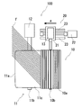
- FIG. 1 is a schematic front view of a glass chopped strand manufacturing apparatus.
- FIG. 2 is a schematic plan view of a glass chopped strand manufacturing apparatus.
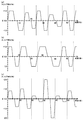
- FIG. 3 is a time chart showing the time change of the slip ratio of the cutter roll with respect to the rubber roll.
- FIG. 4 is a time chart showing the change over time of the slip ratio of the cutter roll with respect to the rubber roll.
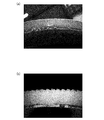
- FIG. 5 is a photograph of (a) the surface of a rubber roll used in a glass chopped strand manufacturing apparatus according to the present invention, and (b) the surface of a rubber roll used in a conventional glass chopped strand manufacturing apparatus.
- FIG. 6 is a schematic plan view of a glass chopped strand manufacturing apparatus provided with a polishing means.
- FIG. 1 is a schematic front view of a glass chopped strand manufacturing apparatus 100.
- FIG. 2 is a schematic plan view of the glass chopped strand manufacturing apparatus 100.
- the glass chopped strand manufacturing apparatus 100 is an apparatus for manufacturing the glass chopped strand G by cutting the glass strand F into a predetermined length as shown in FIGS. 1 and 2, and the cutting blade 10a in the circumferential direction.
- the cutter roll 10 is mounted at regular intervals and radially with respect to the rotation axis, and the rubber roll 11 is formed by covering the roller core 11d with an elastic body 11c.
- a white arrow shown in FIG. 1 indicates the rotation direction of the cutter roll 10 and the rubber roll 11, and a black arrow shown in FIGS. 1 and 2 indicates the moving direction of the cutter roll 10.
- the rubber roll 11 is pivotally supported so as to be rotatable around the shaft center 11 b and is driven to rotate at a constant peripheral speed by the first motor 12.
- the size of the rubber roll 11 can be changed according to the type of the glass chopped strand G to be manufactured, the manufacturing scale, etc.
- the diameter of the rubber roll 11 (including the elastic body 11c) is 250 to 400 mm
- the width direction of the rubber roll 11 The length is set to 250 to 450 mm
- the thickness of the elastic body 11c is set to 5 to 100 mm.
- the material used for the elastic body 11c can be appropriately selected according to the properties of the glass strand F to be cut, but a rubber material having appropriate elasticity and resistance to deterioration is preferable.
- urethane rubber fluorine
- examples thereof include rubber, silicone rubber, chloroprene rubber, acrylic rubber, isoprene rubber, nitrile rubber, styrene rubber, hyperon rubber, and natural rubber.
- the rubber roll 11 configured as described above conveys 1 to 100 glass strands F supplied from the upstream to the downstream while being placed on the surface 11a. That is, the conveyance process in the manufacturing method of the glass chopped strand of this invention is performed.
- the cutter roll 10 is attached so that the cutting blades 10a protrude radially from the axial center 10b at equal intervals (for example, 3 mm) in the circumferential direction.
- the shaft center 10 b of the cutter roll 10 is disposed so as to be substantially parallel to the shaft center 11 b of the rubber roll 11, and is disposed so that the cutting blade 10 a of the cutter roll 10 can come into contact with the surface 11 a of the rubber roll 11.
- the cutter roll 10 is rotatably supported around an axis 10b, and is driven to rotate by the second motor 13 in accordance with the peripheral speed of the rubber roll 11.
- the cutter roll 10 is in contact with the surface 11a of the rubber roll 11 while rotating.
- the strand F is cut.
- the cutting process in the manufacturing method of the glass chopped strand of this invention is performed.
- the peripheral speed of the cutter roll 10 is faster than the peripheral speed of the rubber roll 11, and can be adjusted to vary according to a certain rule or randomly.
- the glass chopped strands G that are cut when the glass strands F are cut by entering the cutter blades 10 and the rubber rolls 11 are appropriately clogged.
- the cutting blade 10a is prevented from biting into the same portion of the surface 11a of the rubber roll 11, and the progress of deterioration of the rubber roll 11 is suppressed.
- the size of the cutter roll 10 can be changed according to the type and production scale of the glass chopped strand G to be manufactured.
- the diameter of the cutter roll 10 (including the cutting blade 10a) is set to 50 to 100 mm
- the length in the width direction of the cutter roll 10 is set equal to or slightly longer than the length in the width direction of the rubber roll 11. Thereby, the cutting edge of the cutting blade 10a can be reliably contacted over the entire width direction of the rubber roll 11.
- the cutter roll 10 presses the cutting blade 10a against the surface 11a of the rubber roll 11 with a predetermined pressure in order to give a shearing force to the glass strand F.
- the cutting blade 10a of the cutter roll 10 bites into the surface 11a of the rubber roll 11, and the surface 11a of the rubber roll 11 is shaved.
- the diameter of the rubber roll 11 gradually decreases, and the pressing force of the cutter roll 10 on the surface 11a of the rubber roll 11 is weakened. Therefore, the cutter roll 10 is connected to a slide means 20 for approaching the rubber roll 11 in accordance with the deterioration of the rubber roll 11. As shown in FIG.
- the slide means 20 includes a first base 21 on which a second motor 13 that rotates the cutter roll 10 is placed, and a first drive means 22 that moves the first base 21.
- the first base 21 is slidably disposed on a first rail 23 that is disposed in a direction orthogonal to the axis 10b of the cutter roll 10 (the direction of the arrow a).
- the shaft center 10b of the cutter roll 10 and the shaft center 11b of the rubber roll 11 are arranged so as to be substantially parallel, and when the first drive means 22 is driven, the first base 21 moves over the first rail 23 with an arrow. Slide and move in the direction of a.
- a second motor 13 is placed on the first base 21, and the second motor 13 is connected to the cutter roll 10.
- the cutter roll 10 moves to the direction of arrow a, ie, the direction which presses the surface 11a of the rubber roll 11.
- FIG. thereby, the cutter roll 10 can press the cutting blade 10a against the surface 11a of the rubber roll 11 while maintaining the parallel state of the axis 10b of the cutter roll 10 and the axis 11b of the rubber roll 11.
- a stepping motor capable of causing the cutter roll 10 to approach the rubber roll 11 at regular intervals can be used as the first driving means 22.
- control means for controlling the operation of the first motor 12, the second motor 13, and the slide means 20.
- the first motor 12, the second motor 13, and the slide means 20 are sequence-controlled in a predetermined pattern so that the slip rate S of the cutter roll 10 can be changed with respect to the rubber roll 11, which will be described later. Can be executed automatically.
- a general-purpose personal computer or the like can be used as the control means.
- ⁇ Slip rate of cutter roll> On the outer periphery of the cutter roll 10, cutting blades 10 a are provided at equal intervals (for example, 3 mm), and the tips of the cutting blades 10 a come into contact with the surface 11 a of the rubber roll 11.
- the peripheral speed of the outer peripheral surface of the cutter roll 10 is set faster (for example, 273 m / min) than the peripheral speed (for example, 260 m / min) of the outer peripheral surface of the rubber roll 11, the rubber roll 11 and the cutter roll 10
- the cutting blade 10a is warped at the contact portion.
- the glass chopped strand G is pushed out from between the cutting blades 10 a of the cutter roll 10 by the rebounding force of the cutting blade 10 a generated when the warping of the cutting blade 10 a is eliminated, and is efficiently discharged from the cutter roll 10.
- the slip ratio S of the cutter roll 10 with respect to the rubber roll 11 is set to be constant, the frequency at which the cutting blade 10a bites into the same portion of the surface 11a of the rubber roll 11 increases. Thereby, the damage
- the present invention is configured such that the slip ratio S (%) of the cutter roll 10 relative to the rubber roll 11 always varies with a positive value. This variation is performed periodically or randomly.
- the cutting blade 10a of the cutter roll 10 is brought into contact with the surface 11a of the rubber roll 11 while being shifted in the front-rear direction of rotation, so that the surface 11a of the rubber roll 11 is substantially uniform. So that it can be sharpened.
- the slip ratio S (%) of the cutter roll 10 relative to the rubber roll 11 can be expressed by the following formula (1).
- S (%) (v1 / v2 ⁇ 1) ⁇ 100 (1)
- v1 Peripheral speed of the outer peripheral surface of the cutter roll 10
- v2 Peripheral speed of the outer peripheral surface of the rubber roll 11
- the range in which the slip ratio S of the cutter roll 10 with respect to the rubber roll 11 can be taken is 1% to 10%, preferably 2% to 8%, and more preferably 4% to 6%. If the slip rate S of the cutter roll 10 is set to less than 1%, the difference between the peripheral speeds of the cutter roll 10 and the rubber roll 11 is not sufficient, so that the cutting blade 10a pushes out the glass chopped strand G (bounce force) becomes weak. . As a result, the glass chopped strand G may enter between the cutting blades 10a of the cutter roll 10 to cause clogging of the cutter roll 10 and cause a cutting failure of the glass strand F.
- slip rate S of the cutter roll 10 When the slip rate S of the cutter roll 10 is set to be larger than 10%, when the tip of the cutting blade 10a bites into the surface 11a of the rubber roll 11, a load due to warping of the cutting blade 10a becomes excessive, and the cutting blade 10a may be damaged. There is. A method for changing the slip ratio S of the cutter roll 10 relative to the rubber roll 11 will be described below.
- a variation method combining these variation methods The up / down fluctuation amount and the fluctuation time period of the slip ratio S may be changed or changed randomly, or may be changed or changed according to a certain rule.
- up and down fluctuation means that the slip ratio S fluctuates to a value smaller than the reference slip ratio when it is fluctuated to a value smaller than the reference slip ratio after being varied to a value larger than the reference slip ratio. This includes the case where the value is changed to a value larger than the reference slip rate after the adjustment.
- the “time period” represents the time required for the slip rate S to be changed up and down from the reference slip rate to return to the reference slip rate.
- the initial slip rate which is the slip rate S at the start of manufacturing the glass chopped strand G
- the reference slip rate S ′ is set as the reference slip rate S ′
- the slip rate S is determined from the reference slip rate S ′ by a predetermined amount of vertical fluctuation. And fluctuate in a certain time period, and the amount of fluctuation in the vertical direction is varied randomly for each period.
- the reference slip ratio S ′ is set to 4% to 6%
- the vertical fluctuation amount is set to ⁇ 0.4% to ⁇ 2%.
- the reference slip ratio S ′ is set to 4% to 6%, and the vertical fluctuation amount is set to ⁇ 1%. More preferably, the reference slip ratio S ′ is set to 5%, and the vertical fluctuation amount is set to ⁇ 1%.
- the initial slip rate which is the slip rate S at the start of production of the glass chopped strand G
- the slip rate S is constant from the reference slip rate S ′.
- the time period of the fluctuation is changed at random. To change the time period of fluctuation at random, the time until the slip ratio S fluctuates from the value of the reference slip ratio S ′ by a predetermined amount of vertical fluctuation and returns to the same reference slip ratio S ′ again is changed. That is.
- the change width of the time period is preferably set to 10 to 30 seconds.
- the change width of the time period is set to be shorter than 10 seconds, the slip ratio S is too finely changed, so that the load due to the warp of the cutting blade 10a becomes excessive and the cutting blade 10a may be damaged. If the change width of the time period is set longer than 30 seconds, the variation of the slip ratio S is not sufficient, so that the cutting blade 10a easily bites into the same portion of the surface 11a of the rubber roll 11. As a result, a saw-like deep groove is formed on the surface 11a of the rubber roll 11 due to the rebounding force of the cutting blade 10a, and the life of the rubber roll 11 may be shortened.
- 3 and 4 are time charts showing the change over time of the slip ratio S of the cutter roll 10 with respect to the rubber roll 11.
- 3A is a time chart of the slip ratio S according to the first embodiment
- FIG. 3B is a time chart of the slip ratio S according to the second embodiment
- FIG. 3C is according to the third embodiment
- FIG. 4D is a time chart of the slip ratio S according to the fourth embodiment
- FIG. 4E is a time chart of the slip ratio S according to the fifth embodiment.
- the initial slip ratio at the start of manufacturing the glass chopped strand G is set as the reference slip ratio S ′, and the slip ratio S is changed by a predetermined amount of vertical fluctuation from the reference slip ratio S ′.
- the number shown to the right of the reference slip ratio S ′ on the vertical axis represents the actual value of the reference slip ratio, and the vertical axis represents the amount of variation from the reference slip ratio S ′.
- the slip ratio S by making the peripheral speed of the outer peripheral surface of the rubber roll 11 constant and changing the peripheral speed of the outer peripheral surface of the cutter roll 10. Since the peripheral speed of the outer peripheral surface of the rubber roll 11 is constant, the supply rate of the glass strand F supplied to the glass chopped strand manufacturing apparatus 100 can be made constant. As a result, the production amount of the glass chopped strand G per unit time Can be made constant.
- the slip ratio S is randomly varied using both the first variation method and the second variation method.
- Each section delimited by a dotted line in the time chart represents one cycle of the fluctuation of the slip ratio S.
- the reference slip ratio S ′ is set to 6.0%, and the slip ratio S is randomly changed with a vertical fluctuation amount of ⁇ 0.6 to ⁇ 1.0% from the reference slip ratio S ′.
- the time period of vertical fluctuations is randomly changed between 10 seconds and 14 seconds.
- the cutting blade 10 a of the cutter roll 10 is rotated in the front-rear direction with respect to the surface 11 a of the rubber roll 11. It can be made to contact in the state shifted at random. As a result, it is possible to reliably prevent deep grooves from being formed on the surface 11a of the rubber roll 11.
- the vertical fluctuation amount of the slip ratio S is set to be constant, and the time period of the fluctuation of the slip ratio S is randomly changed using the second fluctuation method.
- Each section delimited by a dotted line in the time chart represents one cycle of the fluctuation of the slip ratio S.
- the reference slip rate S ′ is set to 5.0%, the slip rate S is changed by a vertical fluctuation amount of ⁇ 1.0% from the reference slip rate S ′, and the time period of change of the slip rate S is set to 10 It is changed randomly between 2 and 22 seconds.
- the cutting blade 10a of the cutter roll 10 is in contact with the surface 11a of the rubber roll 11 in a state of being randomly shifted in the front-rear direction. Can be made. As a result, it is possible to reliably prevent deep grooves from being formed on the surface 11a of the rubber roll 11.
- the time period of the variation of the slip ratio S is set to be constant, and the vertical variation amount of the slip ratio S is randomly varied using the first variation method.
- Each section delimited by a dotted line in the time chart represents one cycle of the variation of the slip ratio S.
- the reference slip ratio S ′ is set to 4.0%, and the slip ratio S is randomly varied with a vertical fluctuation amount of ⁇ 0.4 to ⁇ 2.0% from the reference slip ratio S ′.
- the time period of the fluctuation is set to 10 seconds.
- the cutting blade 10a of the cutter roll 10 is brought into contact with the surface 11a of the rubber roll 11 in a state of being randomly shifted in the front-rear direction of rotation. be able to. As a result, it is possible to reliably prevent deep grooves from being formed on the surface 11a of the rubber roll 11.
- the slip ratio S is varied according to a certain rule using both the first variation method and the second variation method.
- Each section delimited by a dotted line in the time chart represents one cycle of the variation of the slip ratio S.
- the reference slip rate S ′ is set to 5.0%
- the slip rate S is changed by an amount of vertical fluctuation of ⁇ 0.6 to ⁇ 1.0% from the reference slip rate S ′
- the slip rate S is changed. Is changed between 10 seconds and 14 seconds.
- three cycles of the variation of the slip ratio S are set as one cycle, and this cycle is repeated so that the slip ratio S varies according to a certain rule.
- both the vertical fluctuation amount of the slip rate S and the time period of the fluctuation are changed or changed according to a certain rule, so that the cutting blade 10a of the cutter roll 10 is rotated before and after the surface 11a of the rubber roll 11 is rotated. It is possible to make contact with the direction shifted in a predetermined pattern. As a result, it is possible to reliably prevent a deep groove from being formed on the surface 11a of the rubber roll 11 while reliably reducing the load applied to the cutting blade 10a due to the change in the slip ratio S.
- both the vertical fluctuation amount of the slip ratio S and the time period of the fluctuation are changed or changed. However, as in the second embodiment and the third embodiment described above, either one is made constant. The other may be set to vary or change.
- the slip ratio S is varied by setting the vertical variation amount of the slip ratio S and the time period of the variation constant.
- Each section delimited by a dotted line in the time chart represents one cycle of the variation of the slip ratio S.
- the reference slip rate S ′ is set to 5.0%
- the slip rate S is changed by ⁇ 1.5% up / down fluctuation amount from the reference slip rate S ′
- the time period of change of the slip rate S is 20 Set to seconds.
- the up-and-down fluctuation amount of the slip rate S and the time period of the fluctuation are set to be constant, the load applied to the cutting blade 10a of the cutter roll 10 can be reliably reduced.
- An apparatus for manufacturing glass chopped strands (Example) in which the slip rate of the cutter roll relative to the rubber roll according to the present invention was varied, and an apparatus for manufacturing glass chopped strands (Comparative Example) in which the slip rate of the cutter roll relative to the rubber roll was constant.
- the used rubber roll has a diameter of 370 mm, a length in the width direction of 350 mm, and an elastic body thickness of 100 mm.
- Urethane rubber was used for the elastic body of the rubber roll.
- the peripheral speed of the rubber roll was set to 260 m / min. In the embodiment, as shown in FIG.
- the reference slip ratio is set to 5.0%
- the slip ratio is changed by a vertical fluctuation amount of ⁇ 1.0% from the reference slip ratio
- the slip The time period of fluctuation of the rate S was randomly changed between 10 seconds and 30 seconds.
- the slip ratio was set to 5%.
- the apparatus for producing glass chopped strands of Examples and Comparative Examples was operated for 30 hours, and the deterioration state of the surface of the rubber roll was visually evaluated.
- FIG. 5 shows (a) the surface of a rubber roll used in a glass chopped strand production apparatus according to the present invention (Example), and (b) the surface of a rubber roll used in a conventional glass chopped strand production apparatus (Comparative Example). It is a photograph of. As shown in FIG. 5 (a), the surface of the rubber roll of the example is scraped substantially evenly in the front-rear direction and maintains a smooth state. On the other hand, as shown in FIG. 5 (b), the surface of the rubber roll of the comparative example has a saw-like deep groove, and it can be confirmed that the deterioration is progressing. In addition, clogging of the glass chopped strand into the cutting blade of the cutter roll did not occur in any of the examples and the comparative examples.
- FIG. 6 is a schematic plan view of a glass chopped strand manufacturing apparatus 100 provided with a polishing means 14, which is another embodiment of the glass chopped strand manufacturing apparatus according to the present invention.
- the black arrows shown in FIG. 6 indicate the moving directions of the cutter roll 10 and the polishing means 14.
- the slip rate S of the cutter roll 10 with respect to the rubber roll 11 is changed, and the cutting blade 10a of the cutter roll 10 is brought into contact with the surface 11a of the rubber roll 11 in a state shifted in the front-rear direction.
- polishing is performed to polish the surface 11a of the rubber roll 11 while reciprocating in the width direction of the rubber roll 11 in order to smooth the surface 11a of the rubber roll 11. It is also possible to provide further means 14.
- the polishing unit 14 includes a polishing unit 15 that polishes the surface 11 a of the rubber roll 11, a proximity moving unit 30 that moves the polishing unit 15 so as to be close to the axis 11 b of the rubber roll 11, A width direction moving means 40 for reciprocating the polishing portion 15 in parallel with the width direction of the rubber roll 11 is provided.
- the polishing unit 15 abuts on the surface 11a of the rubber roll 11 by the proximity moving means 30, and polishes the surface 11a of the rubber roll 11 by reciprocating in the width direction of the rubber roll 11 by the width direction moving means 40.
- the width direction moving means 40 is disposed in a direction parallel to the second base 41 on which the polishing portion 15 for polishing the surface 11 a of the rubber roll 11 is placed and the width direction of the rubber roll 11.
- the second rail 42, the rail base 43 that fixes the second rail 42, and the second driving means 44 that moves the second base 41 are provided.
- the polishing portion 15 is fixed to the second base 41 so as to face the surface 11 a of the rubber roll 11.
- the second base 41 slides on the second rail 42 (in the direction of arrow c).
- the polishing unit 15 disposed on the second base 41 reciprocates in the direction of the arrow c, and uniformly polishes the surface 11a of the rubber roll 11.
- the proximity moving means 30 includes third driving means 31 for moving the rail base 43, as shown in FIG.
- the rail base 43 slides on the third rail 32 arranged in a direction orthogonal to the axis 11 b of the rubber roll 11 (direction of arrow b). That is, the polishing unit 15 placed on the second base 41 moves in the direction of the arrow b, that is, the direction in which the surface 11a of the rubber roll 11 is pressed.
- the polishing unit 15 can press the surface 11a of the rubber roll 11 with a predetermined pressure.
- the surface 11 a of the rubber roll 11 is actively smoothed, so that formation of deep grooves on the surface 11 a of the rubber roll 11 is further suppressed.
- the polishing unit 15 constituting the polishing unit 14 may be any as long as the surface 11a of the rubber roll 11 can be uniformly polished.
- a horusoe, a bite blade, a rotating grindstone, an end mill and the like can be mentioned. Among them, a horusoe is preferably used.
- the glass chopped strand production apparatus and production method of the present invention can be used in a production process of cutting glass strands (glass fibers) into glass chopped strands, but fibers other than glass fibers (for example, synthetic fibers, carbons) (Fiber, natural fiber), and further, it can be used in applications for cutting linear objects such as metal wires.
Landscapes
- Engineering & Computer Science (AREA)
- Life Sciences & Earth Sciences (AREA)
- Textile Engineering (AREA)
- Forests & Forestry (AREA)
- Mechanical Engineering (AREA)
- Chemical & Material Sciences (AREA)
- Geochemistry & Mineralogy (AREA)
- Manufacturing & Machinery (AREA)
- General Life Sciences & Earth Sciences (AREA)
- Materials Engineering (AREA)
- Organic Chemistry (AREA)
- Manufacture, Treatment Of Glass Fibers (AREA)
- Preliminary Treatment Of Fibers (AREA)
Abstract
カッターロールの周速をゴムロールの周速より速く設定してもゴムロールの表面に深い溝が形成され難いガラスチョップドストランドの製造装置を提供する。 上流から供給されるガラスストランドFを下流に搬送するゴムロール(11)と、ゴムロール(11)の表面(11a)に当接して回転しながらガラスストランドFを切断するカッターロール(10)と、を備えたガラスチョップドストランドの製造装置(100)であって、ゴムロール(11)及びカッターロール(10)は、以下の式(1)で表されるゴムロール(11)に対するカッターロール(10)のスリップ率S: S(%) = ( v1/v2 - 1 ) × 100 ・・・ (1) v1:カッターロールの外周面の周速 v2:ゴムロールの外周面の周速 が、常に正の値で変動するように夫々回転する。
Description
本発明は、ゴムロールとカッターロールとを備えたガラスチョップドストランドの製造装置、及び製造方法に関する。
ガラスチョップドストランドは、ガラスモノフィラメントを数百~数千本まとめて形成したガラス繊維ストランド(以下、単にガラスストランドと称する)を一定の長さに切断することにより製造される。ガラスストランドの切断工程は、上流から供給されるガラスストランドをゴムロールの表面に載せた状態で、当該ゴムロールの表面にカッターロールを当接させて回転させることにより行われる。カッターロールの表面には、切断刃が等間隔で回転軸を中心に放射状に取り付けられている。ガラスストランドがカッターロールとゴムロールとの間に送り込まれると、ガラスストランドはカッターロールによって一定の長さの短繊維に切断され、ガラスチョップドストランドが生成する。
ここで、カッターロールとゴムロールとを同一の周速で回転させてガラスストランドを切断すると、ガラスチョップドストランドが切断刃の間に入り込み、目詰まりを起こし、排出されなくなることがある。特に、短いガラスチョップドストランドを製造する場合には、切断刃同士の間隔が狭くなり、ガラスチョップドストランドが切断刃の間に入り込んで目詰まりを起こし易い。目詰まりした切断刃でガラスストランドを切断しようとすると、ガラスストランドの切断不良が発生する虞がある。
そこで、特許文献1の長繊維の切断方法では、カッターロールの周速がゴムロールの周速よりも速くなるように設定して、ガラスチョップドストランドがカッターロールの切断刃の間に目詰まりすることを防止している。
特許文献1の長繊維の切断方法では、カッターロールの周速をゴムロールの周速よりも速く設定しているため、カッターロールの切断刃がゴムロールの表面に食い込むと、切断刃の先端部分はゴムロールの周速で回転し、切断刃の根元部分はカッターロールの周速で回転する。この結果、切断刃の先端と根元との間に速度差が生じて、切断刃が反った状態となる。この状態から切断刃の先端がゴムロールの表面から外れて切断刃の反りが解消する際に、切断刃はカッターロールの回転方向に跳ね返る。特許文献1の長繊維の切断方法では、この跳ね返る力を利用して、ガラスチョップドストランドを切断刃の間から押し出して排出させている。しかし、特許文献1の長繊維の切断方法では、カッターロールをゴムロールに対して一定のスリップ率で回転させているため、ゴムロールの表面の同じ箇所にカッターロールの切断刃が食い込み易くなる。その結果、ゴムロールの表面に生じる傷が、切断刃の跳ね返りによって徐々に大きくなり、深い溝を形成してゴムロールの寿命を短くするという新たな問題が発生することになる。
本発明は、上記問題点に鑑みてなされたものであり、カッターロールの周速をゴムロールの周速より速く設定してもゴムロールの表面に深い溝が形成され難いガラスチョップドストランドの製造装置、及び製造方法を提供することを目的とする。
上記課題を解決するための本発明に係るガラスチョップドストランドの製造装置の特徴構成は、
上流から供給されるガラスストランドを下流に搬送するゴムロールと、
前記ゴムロールの表面に当接して回転しながら前記ガラスストランドを切断するカッターロールと、
を備えたガラスチョップドストランドの製造装置であって、
前記ゴムロール及び前記カッターロールは、以下の式(1)で表される前記ゴムロールに対する前記カッターロールのスリップ率S:
S(%) = ( v1/v2 - 1 ) × 100 ・・・ (1)
v1:カッターロールの外周面の周速
v2:ゴムロールの外周面の周速
が、常に正の値で変動するように夫々回転することにある。
上流から供給されるガラスストランドを下流に搬送するゴムロールと、
前記ゴムロールの表面に当接して回転しながら前記ガラスストランドを切断するカッターロールと、
を備えたガラスチョップドストランドの製造装置であって、
前記ゴムロール及び前記カッターロールは、以下の式(1)で表される前記ゴムロールに対する前記カッターロールのスリップ率S:
S(%) = ( v1/v2 - 1 ) × 100 ・・・ (1)
v1:カッターロールの外周面の周速
v2:ゴムロールの外周面の周速
が、常に正の値で変動するように夫々回転することにある。
本構成のガラスチョップドストランドの製造装置は、スリップ率Sが常に正の値で変動するように設定されていることから、カッターロールをゴムロールより速い周速で回転させながら、カッターロールの切断刃をゴムロールの表面に対してずらした状態(ゴムロールの表面の同じ箇所にカッターロールの切断刃が食い込まない状態)で当接させることができる。その結果、カッターロールの切断刃がゴムロールの表面の同じ箇所を傷つけることが抑制され、ゴムロールの表面に深い溝が形成されることを防止することができる。
本発明に係るガラスチョップドストランドの製造装置において、
前記スリップ率Sは、周期的に変動するように設定されていることが好ましい。
前記スリップ率Sは、周期的に変動するように設定されていることが好ましい。
本構成のガラスチョップドストランドの製造装置は、スリップ率Sが周期的に変動するように設定されていることから、カッターロールをゴムロールより速い周速で回転させながら、カッターロールの切断刃をゴムロールの表面に対して回転前後方向に周期的にずらした状態で当接させることができる。その結果、ゴムロールの表面に深い溝が形成されることを確実に防止することができる。
本発明に係るガラスチョップドストランドの製造装置において、
前記スリップ率Sは、ランダムに変動するように設定されていることが好ましい。
前記スリップ率Sは、ランダムに変動するように設定されていることが好ましい。
本構成のガラスチョップドストランドの製造装置は、スリップ率Sがランダムに変動するように設定されていることから、カッターロールをゴムロールより速い周速で回転させながら、カッターロールの切断刃をゴムロールの表面に対して回転前後方向にランダムにずらした状態で当接させることができる。その結果、ゴムロールの表面に深い溝が形成されることを確実に防止することができる。
本発明に係るガラスチョップドストランドの製造装置において、
前記スリップ率Sは、一定の範囲をランダムな時間周期で変動するように設定されていることが好ましい。
前記スリップ率Sは、一定の範囲をランダムな時間周期で変動するように設定されていることが好ましい。
本構成のガラスチョップドストランドの製造装置は、スリップ率Sが一定の範囲をランダムな時間周期で変動するように設定されていることから、切断刃にかかる負荷を軽減するとともに、カッターロールの切断刃をゴムロールの表面に対して回転前後方向にランダムにずらした状態で当接させることができる。その結果、ゴムロールの表面に深い溝が形成されることを確実に防止することができる。
本発明に係るガラスチョップドストランドの製造装置において、
前記スリップ率Sは、ランダムな範囲を一定の時間周期で変動するように設定されていることが好ましい。
前記スリップ率Sは、ランダムな範囲を一定の時間周期で変動するように設定されていることが好ましい。
本構成のガラスチョップドストランドの製造装置は、スリップ率Sがランダムな範囲を一定の時間周期で変動するように設定されていることから、切断刃にかかる負荷を軽減するとともに、カッターロールの切断刃をゴムロールの表面に対して回転前後方向にランダムにずらした状態で当接させることができる。その結果、ゴムロールの表面に深い溝が形成されることを確実に防止することができる。
本発明に係るガラスチョップドストランドの製造装置において、
前記スリップ率Sは、一定の規則で変動するように設定されていることが好ましい。
前記スリップ率Sは、一定の規則で変動するように設定されていることが好ましい。
本構成のガラスチョップドストランドの製造装置は、スリップ率Sが一定の規則で変動するように設定されていることから、切断刃にかかる負荷を確実に軽減しながら、ゴムロールの表面に深い溝が形成されることを効果的に抑制することができる。
本発明に係るガラスチョップドストランドの製造装置において、
前記スリップ率Sは、基準となるスリップ率S´から±1%の範囲で変動するように設定されていることが好ましい。
前記スリップ率Sは、基準となるスリップ率S´から±1%の範囲で変動するように設定されていることが好ましい。
本構成のガラスチョップドストランドの製造装置は、スリップ率Sが基準となるスリップ率S´から±1%の範囲で変動するように設定されていることから、切断刃への負荷を効果的に軽減しながら、ゴムロールの表面に深い溝が形成されることを確実に抑制することができる。
本発明に係るガラスチョップドストランドの製造装置において、
前記スリップ率Sは、シーケンス制御によって変動することが好ましい。
前記スリップ率Sは、シーケンス制御によって変動することが好ましい。
本構成のガラスチョップドストランドの製造装置は、スリップ率Sがシーケンス制御によって変動することから、スリップ率Sの変動操作を自動で実行することができ、その結果、ガラスチョップドストランドの製造効率を向上させることができる。
上記課題を解決するための本発明に係るガラスチョップドストランドの製造方法の特徴構成は、
上流から供給されるガラスストランドをゴムロールにより下流に搬送する搬送工程と、
前記ゴムロールの表面にカッターロールを当接させた状態で、当該カッターロールを回転させながら前記ガラスストランドを切断する切断工程と、
を包含するガラスチョップドストランドの製造方法であって、
前記切断工程の実行中に、前記ゴムロール及び前記カッターロールは、以下の式(1)で表される前記ゴムロールに対する前記カッターロールのスリップ率S:
S(%) = ( v1/v2 - 1 ) × 100 ・・・ (1)
v1:カッターロールの外周面の周速
v2:ゴムロールの外周面の周速
が、常に正の値で変動するように夫々回転することにある。
上流から供給されるガラスストランドをゴムロールにより下流に搬送する搬送工程と、
前記ゴムロールの表面にカッターロールを当接させた状態で、当該カッターロールを回転させながら前記ガラスストランドを切断する切断工程と、
を包含するガラスチョップドストランドの製造方法であって、
前記切断工程の実行中に、前記ゴムロール及び前記カッターロールは、以下の式(1)で表される前記ゴムロールに対する前記カッターロールのスリップ率S:
S(%) = ( v1/v2 - 1 ) × 100 ・・・ (1)
v1:カッターロールの外周面の周速
v2:ゴムロールの外周面の周速
が、常に正の値で変動するように夫々回転することにある。
本構成のガラスチョップドストランドの製造方法は、切断工程において、スリップ率Sが常に正の値で変動するように設定されていることから、カッターロールをゴムロールより速い周速で回転させながら、カッターロールの切断刃をゴムロールの表面に対してずらした状態で当接させることができる。その結果、カッターロールの切断刃がゴムロールの表面の同じ箇所を傷つけることが抑制され、ゴムロールの表面に深い溝が形成されることを防止することができる。
以下、本発明のガラスチョップドストランドの製造装置に関する実施形態を図1~図6に基づいて説明する。ガラスチョップドストランドの製造方法については、製造装置の説明の中で併せて説明する。ただし、本発明は、以下に説明する実施形態や図面に記載される構成に限定されることを意図しない。
<ガラスチョップドストランドの製造装置>
図1は、ガラスチョップドストランドの製造装置100の概略正面図である。図2は、ガラスチョップドストランドの製造装置100の概略平面図である。ガラスチョップドストランドの製造装置100は、図1及び図2に示すように、ガラスストランドFを所定の長さに切断してガラスチョップドストランドGを製造する装置であり、切断刃10aを円周方向に等間隔で且つ回転軸に対して放射状に取り付けたカッターロール10と、ローラ芯11dの周囲に弾性体11cを被覆したゴムロール11とを備えている。図1中に示す白抜きの矢印はカッターロール10及びゴムロール11の回転方向を示し、図1及び図2中に示す黒矢印はカッターロール10の移動方向を示している。
図1は、ガラスチョップドストランドの製造装置100の概略正面図である。図2は、ガラスチョップドストランドの製造装置100の概略平面図である。ガラスチョップドストランドの製造装置100は、図1及び図2に示すように、ガラスストランドFを所定の長さに切断してガラスチョップドストランドGを製造する装置であり、切断刃10aを円周方向に等間隔で且つ回転軸に対して放射状に取り付けたカッターロール10と、ローラ芯11dの周囲に弾性体11cを被覆したゴムロール11とを備えている。図1中に示す白抜きの矢印はカッターロール10及びゴムロール11の回転方向を示し、図1及び図2中に示す黒矢印はカッターロール10の移動方向を示している。
ゴムロール11は、軸心11bの周りで回転可能に軸支されており、第1モータ12により一定の周速で回転駆動される。ゴムロール11のサイズは、製造するガラスチョップドストランドGの種類や製造規模等に応じて変更可能であるが、例えば、ゴムロール11の径(弾性体11cを含む)として250~400mm、ゴムロール11の幅方向の長さとして250~450mm、弾性体11cの厚みとして5~100mmに設定される。弾性体11cに使用される材料は、切断対象のガラスストランドFの性状に応じて適宜選択可能であるが、適度の弾性と耐劣化性とを兼ね備えたゴム材料が好ましく、例えば、ウレタンゴム、フッ素ゴム、シリコーンゴム、クロロプレンゴム、アクリルゴム、イソプレンゴム、ニトリルゴム、スチレンゴム、ハイパロンゴム、天然ゴム等が挙げられる。上記のように構成されたゴムロール11は、上流から供給される1~100本のガラスストランドFを表面11aに載せながら下流に搬送する。すなわち、本発明のガラスチョップドストランドの製造方法における搬送工程が実行される。
カッターロール10は、切断刃10aが円周方向に等間隔(例えば、3mm)で且つ軸心10bから放射状に突出するように取り付けられている。カッターロール10の軸心10bは、ゴムロール11の軸心11bと略平行になるように配置され、ゴムロール11の表面11aにカッターロール10の切断刃10aが当接可能なように配置されている。カッターロール10は、軸心10bの周りで回転可能に軸支されており、第2モータ13によりゴムロール11の周速に応じて回転駆動し、ゴムロール11の表面11aに当接して回転しながらガラスストランドFを切断する。すなわち、本発明のガラスチョップドストランドの製造方法における切断工程が実行される。切断工程の実行中において、カッターロール10の周速は、ゴムロール11の周速よりも速く、さらに一定の規則に従って又はランダムに変動するように調整可能である。詳細は後述するが、カッターロール10及びゴムロール11の周速を適宜調整することにより、ガラスストランドFを切断する際に切断されたガラスチョップドストランドGが切断刃10aの間に入り込んで目詰まりすることを防ぐとともに、ゴムロール11の表面11aの同一箇所に切断刃10aが食い込むことを防止し、ゴムロール11の劣化の進行を抑制している。カッターロール10のサイズは、製造するガラスチョップドストランドGの種類や製造規模等に応じて変更可能であるが、例えば、カッターロール10の径(切断刃10aを含む)は50~100mmに設定され、カッターロール10の幅方向の長さはゴムロール11の幅方向の長さと同等又は若干長めに設定される。これにより、ゴムロール11の幅方向全体に亘って切断刃10aの刃先を確実に当接させることができる。
カッターロール10は、ガラスストランドFに対する剪断力を与えるためにゴムロール11の表面11aに切断刃10aを所定の圧力で押圧している。この押圧により、カッターロール10の切断刃10aは、ゴムロール11の表面11aに食い込み、ゴムロール11の表面11aが削られる。その結果、ゴムロール11の径が徐々に減少し、カッターロール10のゴムロール11の表面11aへの押圧力が弱まる。そこで、カッターロール10には、ゴムロール11の劣化に応じてゴムロール11の方に接近させるためのスライド手段20が接続されている。スライド手段20は、図2に示すように、カッターロール10を回転駆動させる第2モータ13を載置する第1ベース21と、第1ベース21を移動させる第1駆動手段22とを備えている。第1ベース21は、カッターロール10の軸心10bに対して直交する方向(矢印aの方向)に配置された第1レール23の上にスライド可能に配置されている。
カッターロール10の軸心10bとゴムロール11の軸心11bとは、略平行となるように配置されており、第1駆動手段22を駆動させると、第1ベース21が第1レール23上を矢印aの方向にスライド移動する。第1ベース21には第2モータ13が載置され、第2モータ13はカッターロール10と連結されている。このため、第1ベース21がスライド移動すると、カッターロール10は矢印aの方向、すなわちゴムロール11の表面11aを押圧する方向に移動する。これにより、カッターロール10は、カッターロール10の軸心10bとゴムロール11の軸心11bとの平行状態を維持しながら、ゴムロール11の表面11aに切断刃10aを押圧することが可能になる。第1駆動手段22は、例えば、一定時間ごとにカッターロール10をゴムロール11に接近させることができるステッピングモータを使用することができる。
ガラスチョップドストランドの製造装置100においては、上記第1モータ12、第2モータ13、及びスライド手段20の動作を制御する制御手段(図示せず)を設けることが好ましい。予め設定されたプログラムを用いて、第1モータ12、第2モータ13、及びスライド手段20を所定のパターンでシーケンス制御することにより、後述するゴムロール11に対するカッターロール10のスリップ率Sの変動操作を自動で実行することができる。制御手段としては、汎用のパーソナルコンピュータ等を用いることができる。
<カッターロールのスリップ率>
カッターロール10の外周には、切断刃10aが等間隔(例えば、3mm)に設けられ、当該切断刃10aの先端がゴムロール11の表面11aに食い込むように当接する。ここで、ゴムロール11の外周面の周速(例えば、260m/分)よりもカッターロール10の外周面の周速の方を速く設定すると(例えば、273m/分)、ゴムロール11とカッターロール10との当接部分で切断刃10aの反りが発生する。この切断刃10aの反りが解消する際に生じる切断刃10aの跳ね返りの力により、ガラスチョップドストランドGはカッターロール10の切断刃10aの間から押し出されて、カッターロール10から効率よく排出される。しかし、ゴムロール11に対するカッターロール10のスリップ率Sを一定に設定すると、切断刃10aがゴムロール11の表面11aの同じ箇所に食い込む頻度が増加する。これにより、ゴムロール11の表面11aの傷が徐々に大きくなり、ゴムロール11の表面11aに鋸状の深い溝が形成されてゴムロール11の寿命が短くなることがある。これを防止すべく、本発明では、ゴムロール11に対するカッターロール10のスリップ率S(%)が常に正の値で変動するように構成されている。この変動は、周期的又はランダムに行われる。スリップ率Sを周期的又はランダムに変動させることにより、カッターロール10の切断刃10aをゴムロール11の表面11aに対して回転前後方向にずらした状態で当接させ、ゴムロール11の表面11aが略均等に削られるようにしている。その結果、ゴムロール11の表面11aに鋸状の深い溝が形成されることが防止され、ゴムロール11の寿命を延長することができる。ゴムロール11に対するカッターロール10のスリップ率S(%)は、以下の式(1)で表すことができる。
S(%) = ( v1/v2 - 1 ) × 100 ・・・ (1)
v1:カッターロール10の外周面の周速
v2:ゴムロール11の外周面の周速
カッターロール10の外周には、切断刃10aが等間隔(例えば、3mm)に設けられ、当該切断刃10aの先端がゴムロール11の表面11aに食い込むように当接する。ここで、ゴムロール11の外周面の周速(例えば、260m/分)よりもカッターロール10の外周面の周速の方を速く設定すると(例えば、273m/分)、ゴムロール11とカッターロール10との当接部分で切断刃10aの反りが発生する。この切断刃10aの反りが解消する際に生じる切断刃10aの跳ね返りの力により、ガラスチョップドストランドGはカッターロール10の切断刃10aの間から押し出されて、カッターロール10から効率よく排出される。しかし、ゴムロール11に対するカッターロール10のスリップ率Sを一定に設定すると、切断刃10aがゴムロール11の表面11aの同じ箇所に食い込む頻度が増加する。これにより、ゴムロール11の表面11aの傷が徐々に大きくなり、ゴムロール11の表面11aに鋸状の深い溝が形成されてゴムロール11の寿命が短くなることがある。これを防止すべく、本発明では、ゴムロール11に対するカッターロール10のスリップ率S(%)が常に正の値で変動するように構成されている。この変動は、周期的又はランダムに行われる。スリップ率Sを周期的又はランダムに変動させることにより、カッターロール10の切断刃10aをゴムロール11の表面11aに対して回転前後方向にずらした状態で当接させ、ゴムロール11の表面11aが略均等に削られるようにしている。その結果、ゴムロール11の表面11aに鋸状の深い溝が形成されることが防止され、ゴムロール11の寿命を延長することができる。ゴムロール11に対するカッターロール10のスリップ率S(%)は、以下の式(1)で表すことができる。
S(%) = ( v1/v2 - 1 ) × 100 ・・・ (1)
v1:カッターロール10の外周面の周速
v2:ゴムロール11の外周面の周速
ゴムロール11に対するカッターロール10のスリップ率Sの採り得る範囲は、1%~10%であり、好ましくは2%~8%であり、さらに好ましくは4%~6%である。カッターロール10のスリップ率Sを1%未満に設定すると、カッターロール10とゴムロール11との周速の差が十分でないため、切断刃10aがガラスチョップドストランドGを押し出す力(跳ね返り力)が弱くなる。その結果、ガラスチョップドストランドGがカッターロール10の切断刃10aの間に入り込んでカッターロール10の目詰まりを生じさせ、ガラスストランドFの切断不良を発生させる虞がある。カッターロール10のスリップ率Sを10%より大きく設定すると、切断刃10aの先端がゴムロール11の表面11aに食い込む際に、切断刃10aの反りによる負荷が過大になり、切断刃10aを損傷させる虞がある。ゴムロール11に対するカッターロール10のスリップ率Sを変動させる方法を以下に説明する。
スリップ率Sを変動させる方法としては、例えば、(1)スリップ率Sを基準となるスリップ率(基準スリップ率)から一定の時間周期で上下変動させ、上下変動させるスリップ率Sの範囲(上下変動量)を周期毎にランダムに変動させる第1の変動法、(2)スリップ率Sを基準スリップ率から一定の上下変動量で変動させ、変動の時間周期をランダムに変更させる第2の変動法、及び(3)これらの変動法を組み合わせた変動法が挙げられる。スリップ率Sの上下変動量及び変動の時間周期は、ランダムに変動又は変更させても、一定の規則に従って変動又は変更させてもよい。なお、「上下変動」とは、スリップ率Sを、基準スリップ率よりも大きな値に変動させた後に基準スリップ率よりも小さな値まで変動させた場合は勿論、基準スリップ率よりも小さな値に変動させた後に基準スリップ率よりも大きな値までに変動させた場合も含む。また、「時間周期」とは、基準スリップ率からスリップ率Sを上下変動させて基準スリップ率に戻るまでに要した時間を表す。
第1の変動法としては、例えば、ガラスチョップドストランドGの製造開始時のスリップ率Sである初期スリップ率を基準スリップ率S´とし、スリップ率Sを基準スリップ率S´から所定の上下変動量で一定の時間周期で変動させ、この上下変動量を周期毎にランダムに変動させる。第1の変動法では、カッターロール10の切断刃10aに極端な負荷が掛かり難くなり、切断刃10aの損傷を防ぐことができる。基準スリップ率S´は4%~6%に設定され、上下変動量は±0.4%~±2%に設定される。好ましくは、基準スリップ率S´は4%~6%に設定され、上下変動量は±1%に設定される。より好ましくは、基準スリップ率S´は5%に設定され、上下変動量は±1%に設定される。
第2の変動法としては、例えば、ガラスチョップドストランドGの製造開始時のスリップ率Sである初期スリップ率を基準スリップ率S´とし、スリップ率Sを基準スリップ率S´から一定の上下変動量で変動させ、この変動の時間周期をランダムに変更させる。変動の時間周期をランダムに変更させるとは、スリップ率Sが基準スリップ率S´の値から所定の上下変動量で変動して再び同じ基準スリップ率S´の値に戻るまでの時間を変更することである。この時間周期の変更幅は、10秒~30秒に設定することが好ましい。時間周期の変更幅を10秒より短く設定すると、スリップ率Sが細かく変動し過ぎるため、切断刃10aの反りによる負荷が過大になり切断刃10aを損傷させる虞がある。時間周期の変更幅を30秒より長く設定すると、スリップ率Sの変動が十分でないため、ゴムロール11の表面11aの同じ箇所に切断刃10aが食い込み易くなる。その結果、切断刃10aの跳ね返りの力によりゴムロール11の表面11aに鋸状の深い溝が形成され、ゴムロール11の寿命が短くなる虞がある。
以下、ゴムロール11に対するカッターロール10のスリップ率Sを変動させる実施形態について説明する。図3及び図4は、ゴムロール11に対するカッターロール10のスリップ率Sの時間変化を示したタイムチャートである。図3(a)は第1実施形態に係るスリップ率Sのタイムチャート、図3(b)は第2実施形態に係るスリップ率Sのタイムチャート、図3(c)は第3実施形態に係るスリップ率Sのタイムチャート、図4(d)は第4実施形態に係るスリップ率Sのタイムチャート、図4(e)は第5実施形態に係るスリップ率Sのタイムチャートである。何れの実施形態においても、ガラスチョップドストランドGの製造開始時の初期スリップ率を基準スリップ率S´とし、基準スリップ率S´から所定の上下変動量でスリップ率Sを変動させている。縦軸の基準スリップ率S´の右横に示す数字は、基準スリップ率の実際の値を示し、縦軸は、基準スリップ率S´からの変動量を表す。ゴムロール11に対するカッターロール10のスリップ率Sの変動法としては、上記の第1の変動法、第2の変動法、及びこれらを組み合わせた変動法を採用することができる。なお、ゴムロール11の外周面の周速を一定とし、カッターロール10の外周面の周速を変動させることにより、スリップ率Sを変動させることが好ましい。ゴムロール11の外周面の周速が一定であるため、ガラスチョップドストランドの製造装置100に供給されるガラスストランドFの供給速度を一定にでき、その結果、単位時間あたりのガラスチョップドストランドGの製造量を一定にできる。
[第1実施形態]
図3(a)に示す第1実施形態では、第1の変動法及び第2の変動法の両方を用いてスリップ率Sをランダムに変動させている。タイムチャートの点線で区切られた各区間は、スリップ率Sの変動の一周期を表している。基準スリップ率S´を6.0%に設定し、スリップ率Sを、この基準スリップ率S´から±0.6~±1.0%の上下変動量でランダムに変動させ、且つスリップ率Sの上下変動の時間周期を10秒~14秒の間でランダムに変更させている。本実施形態では、スリップ率Sの上下変動量及び変動の時間周期の両方をランダムに変動又は変更させているため、カッターロール10の切断刃10aをゴムロール11の表面11aに対して回転前後方向にランダムにずらした状態で当接させることができる。その結果、ゴムロール11の表面11aに深い溝が形成されることを確実に防止することができる。
図3(a)に示す第1実施形態では、第1の変動法及び第2の変動法の両方を用いてスリップ率Sをランダムに変動させている。タイムチャートの点線で区切られた各区間は、スリップ率Sの変動の一周期を表している。基準スリップ率S´を6.0%に設定し、スリップ率Sを、この基準スリップ率S´から±0.6~±1.0%の上下変動量でランダムに変動させ、且つスリップ率Sの上下変動の時間周期を10秒~14秒の間でランダムに変更させている。本実施形態では、スリップ率Sの上下変動量及び変動の時間周期の両方をランダムに変動又は変更させているため、カッターロール10の切断刃10aをゴムロール11の表面11aに対して回転前後方向にランダムにずらした状態で当接させることができる。その結果、ゴムロール11の表面11aに深い溝が形成されることを確実に防止することができる。
[第2実施形態]
図3(b)に示す第2実施形態では、スリップ率Sの上下変動量を一定に設定し、第2の変動法を用いてスリップ率Sの変動の時間周期をランダムに変更させている。タイムチャートの点線で区切られた各区間は、スリップ率Sの変動の一周期を表している。基準スリップ率S´を5.0%に設定し、スリップ率Sを、この基準スリップ率S´から±1.0%の上下変動量で変動させ、且つスリップ率Sの変動の時間周期を10秒~22秒の間でランダムに変更させている。本実施形態では、スリップ率Sの変動の時間周期をランダムに変更させているため、カッターロール10の切断刃10aをゴムロール11の表面11aに対して回転前後方向にランダムにずらした状態で当接させることができる。その結果、ゴムロール11の表面11aに深い溝が形成されることを確実に防止することができる。
図3(b)に示す第2実施形態では、スリップ率Sの上下変動量を一定に設定し、第2の変動法を用いてスリップ率Sの変動の時間周期をランダムに変更させている。タイムチャートの点線で区切られた各区間は、スリップ率Sの変動の一周期を表している。基準スリップ率S´を5.0%に設定し、スリップ率Sを、この基準スリップ率S´から±1.0%の上下変動量で変動させ、且つスリップ率Sの変動の時間周期を10秒~22秒の間でランダムに変更させている。本実施形態では、スリップ率Sの変動の時間周期をランダムに変更させているため、カッターロール10の切断刃10aをゴムロール11の表面11aに対して回転前後方向にランダムにずらした状態で当接させることができる。その結果、ゴムロール11の表面11aに深い溝が形成されることを確実に防止することができる。
[第3実施形態]
図3(c)に示す第3実施形態では、スリップ率Sの変動の時間周期を一定に設定し、第1の変動法を用いてスリップ率Sの上下変動量をランダムに変動させている。タイムチャートの点線で区切られた各区間はスリップ率Sの変動の一周期を表している。基準スリップ率S´を4.0%に設定し、スリップ率Sを、この基準スリップ率S´から±0.4~±2.0%の上下変動量でランダムに変動させ、且つスリップ率Sの変動の時間周期を10秒に設定している。本実施形態では、スリップ率Sの上下変動量をランダムに変動させているため、カッターロール10の切断刃10aをゴムロール11の表面11aに対して回転前後方向にランダムにずらした状態で当接させることができる。その結果、ゴムロール11の表面11aに深い溝が形成されることを確実に防止することができる。
図3(c)に示す第3実施形態では、スリップ率Sの変動の時間周期を一定に設定し、第1の変動法を用いてスリップ率Sの上下変動量をランダムに変動させている。タイムチャートの点線で区切られた各区間はスリップ率Sの変動の一周期を表している。基準スリップ率S´を4.0%に設定し、スリップ率Sを、この基準スリップ率S´から±0.4~±2.0%の上下変動量でランダムに変動させ、且つスリップ率Sの変動の時間周期を10秒に設定している。本実施形態では、スリップ率Sの上下変動量をランダムに変動させているため、カッターロール10の切断刃10aをゴムロール11の表面11aに対して回転前後方向にランダムにずらした状態で当接させることができる。その結果、ゴムロール11の表面11aに深い溝が形成されることを確実に防止することができる。
[第4実施形態]
図4(d)に示す第4実施形態では、第1の変動法及び第2の変動法の両方を用いてスリップ率Sを一定の規則に従って変動させている。タイムチャートの点線で区切られた各区間はスリップ率Sの変動の一周期を表している。基準スリップ率S´を5.0%に設定し、スリップ率Sを、この基準スリップ率S´から±0.6~±1.0%の上下変動量で変動させ、且つスリップ率Sの変動の時間周期を10秒~14秒の間で変更させている。さらに、スリップ率Sの変動の三周期を1サイクルとして設定し、このサイクルを繰り返してスリップ率Sを一定の規則で変動するようにしている。本実施形態では、スリップ率Sの上下変動量及び変動の時間周期の両方を一定の規則に従って変動又は変更させているため、カッターロール10の切断刃10aをゴムロール11の表面11aに対して回転前後方向に所定のパターンでずらした状態で当接させることができる。その結果、スリップ率Sの変化による切断刃10aにかかる負荷を確実に軽減しながら、ゴムロール11の表面11aに深い溝が形成されることを確実に防止することができる。本実施形態では、スリップ率Sの上下変動量及び変動の時間周期の両方を変動又は変更させているが、上記の第2実施形態及び第3実施形態のように、何れか一方を一定にして、他方を変動又は変更させるように設定してもよい。
図4(d)に示す第4実施形態では、第1の変動法及び第2の変動法の両方を用いてスリップ率Sを一定の規則に従って変動させている。タイムチャートの点線で区切られた各区間はスリップ率Sの変動の一周期を表している。基準スリップ率S´を5.0%に設定し、スリップ率Sを、この基準スリップ率S´から±0.6~±1.0%の上下変動量で変動させ、且つスリップ率Sの変動の時間周期を10秒~14秒の間で変更させている。さらに、スリップ率Sの変動の三周期を1サイクルとして設定し、このサイクルを繰り返してスリップ率Sを一定の規則で変動するようにしている。本実施形態では、スリップ率Sの上下変動量及び変動の時間周期の両方を一定の規則に従って変動又は変更させているため、カッターロール10の切断刃10aをゴムロール11の表面11aに対して回転前後方向に所定のパターンでずらした状態で当接させることができる。その結果、スリップ率Sの変化による切断刃10aにかかる負荷を確実に軽減しながら、ゴムロール11の表面11aに深い溝が形成されることを確実に防止することができる。本実施形態では、スリップ率Sの上下変動量及び変動の時間周期の両方を変動又は変更させているが、上記の第2実施形態及び第3実施形態のように、何れか一方を一定にして、他方を変動又は変更させるように設定してもよい。
[第5実施形態]
図4(e)に示す第5実施形態では、スリップ率Sの上下変動量及び変動の時間周期を一定に設定して、スリップ率Sを変動させている。タイムチャートの点線で区切られた各区間はスリップ率Sの変動の一周期を表している。基準スリップ率S´を5.0%に設定し、スリップ率Sを、この基準スリップ率S´から±1.5%の上下変動量で変動させ、且つスリップ率Sの変動の時間周期を20秒に設定している。本実施形態では、スリップ率Sの上下変動量及び変動の時間周期を一定に設定しているため、カッターロール10の切断刃10aにかかる負荷を確実に軽減することができる。
図4(e)に示す第5実施形態では、スリップ率Sの上下変動量及び変動の時間周期を一定に設定して、スリップ率Sを変動させている。タイムチャートの点線で区切られた各区間はスリップ率Sの変動の一周期を表している。基準スリップ率S´を5.0%に設定し、スリップ率Sを、この基準スリップ率S´から±1.5%の上下変動量で変動させ、且つスリップ率Sの変動の時間周期を20秒に設定している。本実施形態では、スリップ率Sの上下変動量及び変動の時間周期を一定に設定しているため、カッターロール10の切断刃10aにかかる負荷を確実に軽減することができる。
本発明に係るゴムロールに対するカッターロールのスリップ率を変動させたガラスチョップドストランドの製造装置(実施例)と、ゴムロールに対するカッターロールのスリップ率を一定にしたガラスチョップドストランドの製造装置(比較例)とを使用し、ゴムロールの表面の劣化試験を実施した。使用したゴムロールは、径が370mm、幅方向の長さが350mm、弾性体の厚みが100mmである。ゴムロールの弾性体にはウレタンゴムを用いた。ゴムロールの周速を260m/分に設定した。実施例は、図3(b)に示すように、基準スリップ率を5.0%に設定し、スリップ率を、この基準スリップ率から±1.0%の上下変動量で変動させ、且つスリップ率Sの変動の時間周期を10秒~30秒の間でランダムに変更させた。比較例は、スリップ率を5%に設定した。実施例及び比較例のガラスチョップドストランドの製造装置を30時間稼働させ、ゴムロールの表面の劣化状態を目視により評価した。
図5は、(a)本発明に係るガラスチョップドストランドの製造装置で使用したゴムロールの表面(実施例)、及び(b)従来のガラスチョップドストランドの製造装置で使用したゴムロールの表面(比較例)の写真である。図5(a)に示されるように、実施例のゴムロールの表面は回転前後方向で略均等に削られており、平滑な状態を維持している。一方、図5(b)に示されるように、比較例のゴムロールの表面は鋸状の深い溝が形成されており、劣化が進行していることが確認できる。なお、カッターロールの切断刃へのガラスチョップドストランドの目詰まりは、実施例及び比較例の何れにおいても発生しなかった。
〔別実施形態〕
図6は、本発明に係るガラスチョップドストランドの製造装置の別実施形態であり、研磨手段14を備えたガラスチョップドストランドの製造装置100の概略平面図である。図6中に示す黒矢印はカッターロール10及び研磨手段14の移動方向を示している。上記実施形態では、ゴムロール11に対するカッターロール10のスリップ率Sを変動させて、カッターロール10の切断刃10aをゴムロール11の表面11aに対して回転前後方向にずらした状態で当接させることで、ゴムロール11の表面11aに深い溝が形成されることを抑制しているが、ゴムロール11の表面11aを平滑化するため、ゴムロール11の幅方向に往復移動しながらゴムロール11の表面11aを研磨する研磨手段14をさらに設けることも可能である。
図6は、本発明に係るガラスチョップドストランドの製造装置の別実施形態であり、研磨手段14を備えたガラスチョップドストランドの製造装置100の概略平面図である。図6中に示す黒矢印はカッターロール10及び研磨手段14の移動方向を示している。上記実施形態では、ゴムロール11に対するカッターロール10のスリップ率Sを変動させて、カッターロール10の切断刃10aをゴムロール11の表面11aに対して回転前後方向にずらした状態で当接させることで、ゴムロール11の表面11aに深い溝が形成されることを抑制しているが、ゴムロール11の表面11aを平滑化するため、ゴムロール11の幅方向に往復移動しながらゴムロール11の表面11aを研磨する研磨手段14をさらに設けることも可能である。
研磨手段14は、図6に示すように、ゴムロール11の表面11aを研磨する研磨部15と、研磨部15をゴムロール11の軸心11bに対して近接するように移動させる近接移動手段30と、研磨部15をゴムロール11の幅方向と平行に往復移動させる幅方向移動手段40とを備えている。研磨部15は、近接移動手段30によりゴムロール11の表面11aに当接し、幅方向移動手段40によりゴムロール11の幅方向に往復移動することで、ゴムロール11の表面11aを研磨する。
幅方向移動手段40は、図6に示すように、ゴムロール11の表面11aを研磨する研磨部15を載置する第2ベース41と、ゴムロール11の幅方向に対して平行となる方向に配置された第2レール42と、第2レール42を固定するレール台43と、第2ベース41を移動させる第2駆動手段44とを備えている。第2ベース41には、研磨部15がゴムロール11の表面11aと対向するように固定されている。第2ベース41は、第2駆動手段44から駆動力を受けると、第2レール42の上をスライド移動する(矢印cの方向)。これにより、第2ベース41上に配置された研磨部15は、矢印cの方向に往復移動し、ゴムロール11の表面11aを均一に研磨する。
近接移動手段30は、図6に示すように、レール台43を移動させる第3駆動手段31を備えている。レール台43は、第3駆動手段31から駆動力を受けると、ゴムロール11の軸心11bに対して直交する方向に配置された第3レール32の上をスライド移動する(矢印bの方向)。つまり、第2ベース41上に載置された研磨部15は、矢印bの方向、すなわちゴムロール11の表面11aを押圧する方向に移動する。これにより、研磨部15は、ゴムロール11の表面11aを所定の圧力で押圧することが可能となる。
このような研磨手段14を設けることにより、ゴムロール11の表面11aが積極的に平滑化されるため、ゴムロール11の表面11aに深い溝が形成することがさらに抑制される。なお、研磨手段14を構成する研磨部15は、ゴムロール11の表面11aを均一に研磨できるものであればよい。例えば、ホルソー、バイト刃、回転砥石、エンドミル等が挙げられるが、その中でもホルソーが好適に使用される。
本発明のガラスチョップドストランドの製造装置、及び製造方法は、ガラスストランド(ガラス繊維)を、ガラスチョップドストランドに切断する製造工程において利用可能であるが、ガラス繊維以外の繊維(例えば、合成繊維、炭素繊維、天然繊維)や、さらには金属線等の線状物を切断する用途においても利用可能である。
10 カッターロール
11 ゴムロール
11a 表面
100 ガラスチョップドストランドの製造装置
F ガラスストランド
S スリップ率
S´ 基準スリップ率
11 ゴムロール
11a 表面
100 ガラスチョップドストランドの製造装置
F ガラスストランド
S スリップ率
S´ 基準スリップ率
Claims (9)
- 上流から供給されるガラスストランドを下流に搬送するゴムロールと、
前記ゴムロールの表面に当接して回転しながら前記ガラスストランドを切断するカッターロールと、
を備えたガラスチョップドストランドの製造装置であって、
前記ゴムロール及び前記カッターロールは、以下の式(1)で表される前記ゴムロールに対する前記カッターロールのスリップ率S:
S(%) = ( v1/v2 - 1 ) × 100 ・・・ (1)
v1:カッターロールの外周面の周速
v2:ゴムロールの外周面の周速
が、常に正の値で変動するように夫々回転するガラスチョップドストランドの製造装置。 - 前記スリップ率Sは、周期的に変動するように設定されている請求項1に記載のガラスチョップドストランドの製造装置。
- 前記スリップ率Sは、ランダムに変動するように設定されている請求項1に記載のガラスチョップドストランドの製造装置。
- 前記スリップ率Sは、一定の範囲をランダムな時間周期で変動するように設定されている請求項1に記載のガラスチョップドストランドの製造装置。
- 前記スリップ率Sは、ランダムな範囲を一定の時間周期で変動するように設定されている請求項1に記載のガラスチョップドストランドの製造装置。
- 前記スリップ率Sは、一定の規則で変動するように設定されている請求項1に記載のガラスチョップドストランドの製造装置。
- 前記スリップ率Sは、基準となるスリップ率S´から±1%の範囲で変動するように設定されている請求項1~6の何れか一項に記載のガラスチョップドストランドの製造装置。
- 前記スリップ率Sは、シーケンス制御によって変動する請求項1~7の何れか一項に記載のガラスチョップドストランドの製造装置。
- 上流から供給されるガラスストランドをゴムロールにより下流に搬送する搬送工程と、
前記ゴムロールの表面にカッターロールを当接させた状態で、当該カッターロールを回転させながら前記ガラスストランドを切断する切断工程と、
を包含するガラスチョップドストランドの製造方法であって、
前記切断工程の実行中に、前記ゴムロール及び前記カッターロールは、以下の式(1)で表される前記ゴムロールに対する前記カッターロールのスリップ率S:
S(%) = ( v1/v2 - 1 ) × 100 ・・・ (1)
v1:カッターロールの外周面の周速
v2:ゴムロールの外周面の周速
が、常に正の値で変動するように夫々回転するガラスチョップドストランドの製造方法。
Priority Applications (1)
| Application Number | Priority Date | Filing Date | Title |
|---|---|---|---|
| CN201480012431.8A CN105121718B (zh) | 2013-03-19 | 2014-03-10 | 玻璃纤维短切原丝的制造装置以及制造方法 |
Applications Claiming Priority (2)
| Application Number | Priority Date | Filing Date | Title |
|---|---|---|---|
| JP2013-056157 | 2013-03-19 | ||
| JP2013056157 | 2013-03-19 |
Publications (1)
| Publication Number | Publication Date |
|---|---|
| WO2014148288A1 true WO2014148288A1 (ja) | 2014-09-25 |
Family
ID=51579975
Family Applications (1)
| Application Number | Title | Priority Date | Filing Date |
|---|---|---|---|
| PCT/JP2014/056126 Ceased WO2014148288A1 (ja) | 2013-03-19 | 2014-03-10 | ガラスチョップドストランドの製造装置、及び製造方法 |
Country Status (4)
| Country | Link |
|---|---|
| JP (1) | JP6353246B2 (ja) |
| CN (1) | CN105121718B (ja) |
| MY (1) | MY176311A (ja) |
| WO (1) | WO2014148288A1 (ja) |
Cited By (1)
| Publication number | Priority date | Publication date | Assignee | Title |
|---|---|---|---|---|
| JP2021017664A (ja) * | 2019-07-18 | 2021-02-15 | 日本電気硝子株式会社 | 弾性ロールの製造方法 |
Families Citing this family (4)
| Publication number | Priority date | Publication date | Assignee | Title |
|---|---|---|---|---|
| JP6764580B2 (ja) * | 2016-10-05 | 2020-10-07 | 東レ株式会社 | チョップド繊維束の製造装置および製造方法 |
| CN107243942A (zh) * | 2017-07-20 | 2017-10-13 | 苏州市金翔钛设备有限公司 | 条状物切断机构 |
| JP7604802B2 (ja) * | 2020-08-05 | 2024-12-24 | 三菱ケミカル株式会社 | Cf-smcおよびcf-smcの製造方法 |
| CN112847539A (zh) * | 2020-12-31 | 2021-05-28 | 中交西安筑路机械有限公司 | 一种纤维切割装置及方法 |
Citations (5)
| Publication number | Priority date | Publication date | Assignee | Title |
|---|---|---|---|---|
| JPS5035420Y1 (ja) * | 1969-05-27 | 1975-10-15 | ||
| JPS55150998A (en) * | 1979-05-15 | 1980-11-25 | Ward Machinery Co | Method and device for improving effective life cover of amble roll of rotary die cutter |
| JPS6327237A (ja) * | 1986-05-21 | 1988-02-04 | ザ ワ−ド マシナリイ カンパニイ | 回転ダイカット装置 |
| JPH09119025A (ja) * | 1995-10-27 | 1997-05-06 | Nippon Electric Glass Co Ltd | 長繊維の切断方法 |
| JP2001200430A (ja) * | 2000-01-14 | 2001-07-27 | Teijin Ltd | 繊維束切断装置 |
Family Cites Families (3)
| Publication number | Priority date | Publication date | Assignee | Title |
|---|---|---|---|---|
| JPH0670291B2 (ja) * | 1990-08-06 | 1994-09-07 | 日清紡績株式会社 | 不良篠処理装置 |
| US20040003699A1 (en) * | 2002-07-02 | 2004-01-08 | The Procter & Gamble Company | Rotary apparatus for severing web materials |
| JP5470089B2 (ja) * | 2010-02-23 | 2014-04-16 | ユニ・チャーム株式会社 | カッター装置 |
-
2014
- 2014-03-10 JP JP2014046005A patent/JP6353246B2/ja active Active
- 2014-03-10 MY MYPI2015703260A patent/MY176311A/en unknown
- 2014-03-10 CN CN201480012431.8A patent/CN105121718B/zh active Active
- 2014-03-10 WO PCT/JP2014/056126 patent/WO2014148288A1/ja not_active Ceased
Patent Citations (5)
| Publication number | Priority date | Publication date | Assignee | Title |
|---|---|---|---|---|
| JPS5035420Y1 (ja) * | 1969-05-27 | 1975-10-15 | ||
| JPS55150998A (en) * | 1979-05-15 | 1980-11-25 | Ward Machinery Co | Method and device for improving effective life cover of amble roll of rotary die cutter |
| JPS6327237A (ja) * | 1986-05-21 | 1988-02-04 | ザ ワ−ド マシナリイ カンパニイ | 回転ダイカット装置 |
| JPH09119025A (ja) * | 1995-10-27 | 1997-05-06 | Nippon Electric Glass Co Ltd | 長繊維の切断方法 |
| JP2001200430A (ja) * | 2000-01-14 | 2001-07-27 | Teijin Ltd | 繊維束切断装置 |
Cited By (1)
| Publication number | Priority date | Publication date | Assignee | Title |
|---|---|---|---|---|
| JP2021017664A (ja) * | 2019-07-18 | 2021-02-15 | 日本電気硝子株式会社 | 弾性ロールの製造方法 |
Also Published As
| Publication number | Publication date |
|---|---|
| CN105121718B (zh) | 2017-11-21 |
| JP6353246B2 (ja) | 2018-07-04 |
| MY176311A (en) | 2020-07-28 |
| JP2014205942A (ja) | 2014-10-30 |
| CN105121718A (zh) | 2015-12-02 |
Similar Documents
| Publication | Publication Date | Title |
|---|---|---|
| JP6353246B2 (ja) | ガラスチョップドストランドの製造装置、及び製造方法 | |
| JP6200831B2 (ja) | ガラスチョップドストランドの製造装置、ゴムロールの表面維持方法、及びガラスチョップドストランドの製造方法 | |
| CN105492691B (zh) | 用于生产纤维材料的幅材的装置和方法 | |
| JP6326070B2 (ja) | スライシング・テンション下で、クリンプの特性が維持される構造化されたソーワイヤ | |
| KR20160048787A (ko) | 잉곳의 절단방법 및 와이어 쏘 | |
| TW202126452A (zh) | 線鋸之運轉重啟方法 | |
| WO2014142058A1 (ja) | センタレス研磨装置 | |
| JP2011218547A (ja) | ダイ本体からハニカム押出ダイを作製する方法 | |
| CN105636742A (zh) | 工件的切断方法 | |
| JP6080753B2 (ja) | ワイヤソーの運転再開方法 | |
| JP6387296B2 (ja) | シート状部材の溝形成装置及び溝形成方法 | |
| KR101899683B1 (ko) | 소재 버어 제거 장치 | |
| JP6522406B2 (ja) | タイヤ用ゴムのトッピング装置 | |
| CN203993423U (zh) | 一种金属带材在机特型砂轮研磨修边去毛刺装置 | |
| JP2015174241A (ja) | 帯状ゴム材料とその製造方法および製造装置 | |
| JP7753336B2 (ja) | ワークピースから複数のスライスを同時にスライスするための方法および装置 | |
| JP2011079073A (ja) | 固定砥粒式ソーワイヤの製造方法 | |
| WO2019008530A1 (en) | METHOD FOR WINDING A CUTTING WIRE | |
| CN108778623B (zh) | 线锯装置的制造方法及线锯装置 | |
| KR102783876B1 (ko) | 제지 및 목재용 나이프 자동 연마장치 | |
| RU59476U1 (ru) | Устройство для разрезания покрышки | |
| JP2019123231A (ja) | 未加硫ゴムベルト形成装置、及び未加硫ゴムベルト形成方法 | |
| JP2010052113A (ja) | 切断装置およびループの製造方法 | |
| RU2318662C1 (ru) | Устройство для разрезания покрышки | |
| JP5861062B2 (ja) | ワイヤーソーとワイヤーソーを用いたシリコン製造方法 |
Legal Events
| Date | Code | Title | Description |
|---|---|---|---|
| 121 | Ep: the epo has been informed by wipo that ep was designated in this application |
Ref document number: 14767336 Country of ref document: EP Kind code of ref document: A1 |
|
| NENP | Non-entry into the national phase |
Ref country code: DE |
|
| 122 | Ep: pct application non-entry in european phase |
Ref document number: 14767336 Country of ref document: EP Kind code of ref document: A1 |