WO2014147878A1 - Structure de support d'arbre rotatif - Google Patents
Structure de support d'arbre rotatif Download PDFInfo
- Publication number
- WO2014147878A1 WO2014147878A1 PCT/JP2013/078451 JP2013078451W WO2014147878A1 WO 2014147878 A1 WO2014147878 A1 WO 2014147878A1 JP 2013078451 W JP2013078451 W JP 2013078451W WO 2014147878 A1 WO2014147878 A1 WO 2014147878A1
- Authority
- WO
- WIPO (PCT)
- Prior art keywords
- thrust bearing
- support
- thrust
- rotating shaft
- casing
- Prior art date
Links
Images


Classifications
-
- F—MECHANICAL ENGINEERING; LIGHTING; HEATING; WEAPONS; BLASTING
- F16—ENGINEERING ELEMENTS AND UNITS; GENERAL MEASURES FOR PRODUCING AND MAINTAINING EFFECTIVE FUNCTIONING OF MACHINES OR INSTALLATIONS; THERMAL INSULATION IN GENERAL
- F16C—SHAFTS; FLEXIBLE SHAFTS; ELEMENTS OR CRANKSHAFT MECHANISMS; ROTARY BODIES OTHER THAN GEARING ELEMENTS; BEARINGS
- F16C23/00—Bearings for exclusively rotary movement adjustable for aligning or positioning
- F16C23/02—Sliding-contact bearings
- F16C23/04—Sliding-contact bearings self-adjusting
-
- F—MECHANICAL ENGINEERING; LIGHTING; HEATING; WEAPONS; BLASTING
- F16—ENGINEERING ELEMENTS AND UNITS; GENERAL MEASURES FOR PRODUCING AND MAINTAINING EFFECTIVE FUNCTIONING OF MACHINES OR INSTALLATIONS; THERMAL INSULATION IN GENERAL
- F16C—SHAFTS; FLEXIBLE SHAFTS; ELEMENTS OR CRANKSHAFT MECHANISMS; ROTARY BODIES OTHER THAN GEARING ELEMENTS; BEARINGS
- F16C17/00—Sliding-contact bearings for exclusively rotary movement
- F16C17/04—Sliding-contact bearings for exclusively rotary movement for axial load only
- F16C17/06—Sliding-contact bearings for exclusively rotary movement for axial load only with tiltably-supported segments, e.g. Michell bearings
-
- F—MECHANICAL ENGINEERING; LIGHTING; HEATING; WEAPONS; BLASTING
- F16—ENGINEERING ELEMENTS AND UNITS; GENERAL MEASURES FOR PRODUCING AND MAINTAINING EFFECTIVE FUNCTIONING OF MACHINES OR INSTALLATIONS; THERMAL INSULATION IN GENERAL
- F16C—SHAFTS; FLEXIBLE SHAFTS; ELEMENTS OR CRANKSHAFT MECHANISMS; ROTARY BODIES OTHER THAN GEARING ELEMENTS; BEARINGS
- F16C17/00—Sliding-contact bearings for exclusively rotary movement
- F16C17/12—Sliding-contact bearings for exclusively rotary movement characterised by features not related to the direction of the load
- F16C17/24—Sliding-contact bearings for exclusively rotary movement characterised by features not related to the direction of the load with devices affected by abnormal or undesired positions, e.g. for preventing overheating, for safety
- F16C17/243—Sliding-contact bearings for exclusively rotary movement characterised by features not related to the direction of the load with devices affected by abnormal or undesired positions, e.g. for preventing overheating, for safety related to temperature and heat, e.g. for preventing overheating
Definitions
- the present invention relates to a rotating shaft support structure that supports the rotating shaft in the thrust direction.
- Rotating machines such as gas turbines and steam turbines are mechanisms that rotate the rotating shaft.
- Some rotary machines having such a rotary shaft are provided with a thrust bearing in order to receive a thrust force and regulate a position in a direction parallel to the rotary shaft in the thrust direction.
- the thrust bearing may be provided with a mechanism for adjusting the mounting position.
- Patent Document 1 describes that the thrust bearing is provided with an adjustment liner between the bearing case and the mounting position with respect to the bearing case.
- the purpose of the adjustment liner is to adjust the axial position of the thrust bearing using a member having an appropriate and uniform thickness when the thrust bearing is mounted in the bearing case. Therefore, even when an adjusting mechanism such as an adjusting liner is provided and a thrust bearing is mounted on the rotating shaft, the rotating shaft is bent due to thermal expansion of the shaft or the casing or the own weight of the shaft, thereby causing an inclination. Therefore, the load on the contact surface with the rotating shaft of the thrust bearing becomes non-uniform, and a load larger than the other portions may act on a part of the contact surface. If the load on a part of the thrust bearing becomes large and the thrust bearing is damaged and cannot support the rotating shaft, a rotating machine such as a gas turbine or a steam turbine may not be operated.
- This invention solves the subject mentioned above, and aims at providing the rotating shaft support structure which can support a rotating shaft for a longer period.
- the rotating shaft support structure of the present invention for achieving the above object is a rotating shaft support structure for supporting a rotating shaft on which a thrust collar protruding radially outward is formed, facing the thrust collar, and A thrust bearing that supports a surface orthogonal to the axial direction of the rotating shaft of the thrust collar with a support surface, and a support mechanism that supports the thrust bearing in the axial direction from the surface side of the support surface opposite to the thrust collar. And the side of the support mechanism that faces the end face of the thrust bearing is inclined in a direction perpendicular to the direction in which the rotating shaft is inclined.
- the present invention it is possible to suppress a load from being concentrated on a part of the thrust bearing in the rotation direction of the rotating shaft, and to extend the life of the thrust bearing. Thereby, a rotating shaft can be supported for a longer period.
- the thrust bearing faces each of an upstream surface and a downstream surface that are two surfaces orthogonal to the axial direction of the thrust collar with the thrust collar interposed therebetween.
- a first support mechanism disposed on the further downstream side of the thrust bearing disposed on the downstream side of the thrust collar in the extending direction of the rotary shaft.
- a second support mechanism disposed further upstream of the thrust bearing disposed on the upstream side of the thrust collar, the first support mechanism having a surface facing the upstream side downstream of the thrust collar.
- the second support mechanism is The surface facing the downstream side in the direction faces the axial end surface of the thrust bearing disposed on the upstream side of the thrust collar, and in the direction toward the downstream side in the axial direction toward the upper side in the radial direction. You may arrange
- both ends of the rotating shaft in the thrust direction can be supported by the thrust bearing and the support mechanism, and the load is concentrated on a part of the thrust bearing regardless of the thrust force acting in any direction. Therefore, the life of the thrust bearing can be extended.
- the support mechanism includes an adjustment liner fixed to the thrust bearing, and the adjustment liner is an end portion on the opposite side in the radial direction from the radial end portion around the rotary shaft.
- the thickness may gradually change toward.
- the present invention by adjusting the direction of the thrust bearing with the adjustment liner, it is possible to suppress a load from being concentrated on a part of the thrust bearing in the rotation direction of the rotating shaft, and to further increase the life of the thrust bearing. Can be long.
- each of the first support mechanism and the second support mechanism includes an adjustment liner fixed to the thrust bearing, and the adjustment liner is a radial end portion around the rotation shaft.
- the thickness of the adjustment liner of the first support mechanism is gradually changed from the adjustment liner of the first support mechanism to the adjustment liner of the second support mechanism. You may arrange
- the mutually facing surfaces of the first support mechanism and the second support mechanism are parallel to each other. Therefore, the support mechanism and the thrust bearing can contact with each other on a uniform surface, and a uniform thrust load can be transmitted through the thrust collar.
- the support mechanism includes a casing in which the rotary shaft is held inside and a casing disposed on a surface side opposite to the support surface of the thrust bearing, and inserted into the casing. And an adjustment mechanism having a plurality of bolts whose end surfaces on the thrust bearing side are in contact with the thrust bearing, wherein the adjustment mechanism includes a plurality of the bolts arranged around the rotation shaft, The protruding amount of movement may change according to the position around the rotation axis.
- the present invention by adjusting the direction of the thrust bearing according to the position of the bolt, it is possible to suppress the load from being concentrated on a part of the thrust bearing in the rotational direction of the rotating shaft, and to improve the life of the thrust bearing. Can be longer. Further, fine adjustment can be easily performed.
- the supporting mechanism includes a casing in which the rotating shaft is held inside and a casing disposed on the surface side opposite to the supporting surface of the thrust bearing, and the casing includes:
- the thrust bearing may be supported from a surface opposite to the support surface, and the supported surface may be inclined with respect to the vertical direction.
- the present invention by adjusting the direction of the thrust bearing by processing the casing, it is possible to suppress a load from being concentrated on a part of the thrust bearing in the rotation direction of the rotating shaft.
- the lifetime can be extended.
- the support mechanism may include the support surface of the thrust bearing, and the support surface may be inclined with respect to a vertical direction.
- the present invention by adjusting the direction of the thrust bearing by processing the thrust bearing, it is possible to suppress a load from being concentrated on a part of the thrust bearing in the rotation direction of the rotating shaft.
- the lifetime of can be made longer.
- the thrust bearing is disposed on the support surface, a plurality of the thrust bearings are disposed in the circumferential direction of the rotary shaft, and a pad that slides with the thrust collar, and a surface opposite to the support surface.
- the pad support means may be supported by the support mechanism, and the pad support means may support the pad in a state of being movable with respect to a plane perpendicular to the rotation axis. .
- the pad movable by making the pad movable, it is possible to suppress a load from being concentrated on a part of the thrust bearing in the rotational direction of the rotating shaft even when the pad is moved.
- the lifetime of can be made longer.
- the thrust bearing can be tilted according to the rotating shaft by tilting the end surface of the supporting mechanism that supports the thrust bearing according to the tilt of the rotating shaft. Therefore, it can suppress that a load concentrates on a part of thrust bearing in the rotation direction of a rotating shaft, and can extend the lifetime of a thrust bearing. Further, the rotating shaft can be supported for a longer period.
- FIG. 1 is a schematic diagram illustrating a schematic configuration of a gas turbine including a thrust bearing mechanism that is an embodiment of a rotating shaft support structure.
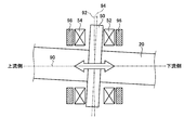
- FIG. 2 is a sectional view showing a schematic configuration of the thrust bearing mechanism of the present embodiment.
- FIG. 3 is a cross-sectional view showing a schematic configuration of the thrust bearing mechanism of the present embodiment.
- FIG. 4 is a front view showing a schematic configuration of the thrust bearing of the present embodiment.
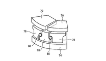
- FIG. 5 is a perspective view showing a part of the thrust bearing shown in FIG. 6 is a developed side view showing a part of the thrust bearing shown in FIG.
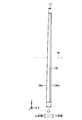
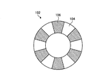
- FIG. 7 is a front view illustrating a schematic configuration of the adjustment liner according to the first support mechanism of the present embodiment.
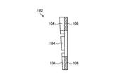
- FIG. 8 is a side view showing a schematic configuration of the adjustment liner shown in FIG. 7.
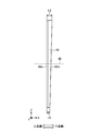
- FIG. 9 is a front view illustrating a schematic configuration of the adjustment liner according to the second support mechanism of the present embodiment.
- FIG. 10 is a side view illustrating a schematic configuration of the adjustment liner illustrated in FIG. 9.
- FIG. 11 is an explanatory diagram for explaining the function of the thrust bearing mechanism of the present embodiment.
- FIG. 12 is an explanatory diagram for explaining the function of the thrust bearing mechanism of the comparative example.
- FIG. 13 is a front view showing a schematic configuration of a modified adjustment liner.
- FIG. 14 is a side view showing a schematic configuration of the adjustment liner shown in FIG. 13.
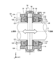
- FIG. 15 is a cross-sectional view showing a schematic configuration of a thrust bearing mechanism of another embodiment.
- FIG. 16 is an enlarged cross-sectional view of the support mechanism of the thrust bearing mechanism shown in FIG.
- FIG. 17 is a cross-sectional view showing a schematic configuration of a thrust bearing mechanism of another embodiment.
- FIG. 18 is a cross-sectional view showing a schematic configuration of a thrust bearing mechanism of another embodiment.
- the bearing device includes a thrust bearing mechanism that is an example of the rotation support structure of the present embodiment.
- a thrust bearing mechanism which is an example of a rotation support structure, is a mechanism that supports a rotating shaft in a thrust direction (axial direction of the rotating shaft), and is disposed between the casing and the rotating shaft.
- the thrust bearing mechanism includes two thrust bearings that respectively face two axial end surfaces of the thrust collar of the rotating shaft, and a support mechanism that is disposed between each thrust bearing and the casing.
- the thrust bearing includes a plurality of bearing pads that support a load from the thrust collar, a leveling mechanism that supports the bearing pads, and a housing that houses the bearings. Further, the support mechanism includes adjustment liners respectively arranged corresponding to the thrust bearings.
- FIG. 1 is a schematic diagram showing a schematic configuration of a gas turbine including a thrust bearing mechanism which is an embodiment of a rotating shaft support structure.
- the gas turbine 10 includes a compressor 12, a combustor 14, a turbine 16, a bearing device 18, a bearing device 19, and a rotating shaft 20.
- Each part of the gas turbine 10 is disposed inside the casing 24.
- a part of the compressor 12 and a part of the turbine 16 are fixed to the rotating shaft 20 and rotate together with the rotating shaft 20.
- the compressor 12 takes in air and compresses it.
- the air compressed by the compressor 12 is supplied to the combustor 14.
- the combustor 14 generates a combustion gas G by mixing fuel with the air compressed by the compressor 12.
- the turbine 16 introduces the combustion gas G generated in the combustor 14 into the inside thereof, expands it, and blows it onto the rotor blades 22 provided on the rotary shaft 20, thereby converting the thermal energy of the combustion gas G into mechanical rotational energy. To generate power.
- the turbine 16 includes a rotating shaft 20, a plurality of moving blades 22 provided on the rotating shaft 20 side, a casing 24 that houses the rotating shaft 20 and the moving blades 22, And a plurality of stationary blades 26 fixed to the casing 24 side.
- the moving blades 22 and the stationary blades 26 are alternately arranged in the axial direction of the rotating shaft 20.
- the moving blade 22 rotates the rotating shaft 20 by the combustion gas G that is injected from the combustor 14 and flows in the axial direction of the rotating shaft 20.
- the rotational energy of the rotating shaft 20 is taken out by a mechanism connected to the rotating shaft 20, for example, a generator.
- the bearing device 18 is provided at the end of the rotary shaft 20 on the compressor 12 side.
- the bearing device 18 includes a journal bearing mechanism 30, a thrust bearing mechanism 40, and a lubricating oil supply mechanism 41.
- the journal bearing mechanism 30 is fixed to the casing 24, receives a radial load of the rotary shaft 20, and restricts the radial movement of the rotary shaft 20 relative to the casing 24.
- the thrust bearing mechanism 40 is fixed to the casing 24, receives an axial load of the rotating shaft 20, and restricts the axial movement of the rotating shaft 20 with respect to the casing 24.
- the lubricating oil supply mechanism 41 supplies and collects lubricating oil to the journal bearing mechanism 30 and the thrust bearing mechanism 40, and circulates the lubricating oil.
- the bearing device 19 is provided at the end of the rotating shaft 20 on the turbine 16 side.
- the bearing device 19 includes a journal bearing mechanism 30 and a lubricating oil supply mechanism 42.
- the journal bearing mechanism 30 is fixed to the casing 24, receives a radial load of the rotary shaft 20, and restricts the radial movement of the rotary shaft 20 relative to the casing 24.
- the lubricating oil supply mechanism 42 supplies the lubricating oil to the journal bearing mechanism 30, collects it, and circulates the lubricating oil.
- the gas turbine 10 is configured as described above, and the bearing devices 18 and 19 support the rotating shaft 20 with respect to the casing 24.
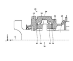
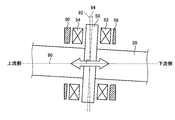
- FIG. 2 is a sectional view showing a schematic configuration of the thrust bearing mechanism of the present embodiment.
- FIG. 3 is a cross-sectional view showing a schematic configuration of the thrust bearing mechanism of the present embodiment.
- the axial direction refers to the direction in which the rotating shaft 20 extends (X-axis direction shown in FIG. 1)
- the radial direction refers to the direction orthogonal to the rotating shaft 20 (Z-axis direction in FIG. 1).
- Y-axis direction means a direction away from the rotating shaft 20
- the inner side in the radial direction means a direction approaching the rotating shaft 20.
- the right side direction on the paper surface of FIG. 1 is referred to as the downstream side (the direction in which the turbine 16 side is viewed from the compressor 12 side), and the left side direction is the upstream side (the direction in which the compressor 12 side is viewed from the turbine 16 side).
- the vertical direction means a direction perpendicular to the horizontal plane.
- the thrust bearing mechanism 40 of the present embodiment is disposed upstream of the center of the rotating shaft 20. Accordingly, the rotary shaft 20 has a portion on the upstream side shorter than the installation position of the thrust bearing mechanism 40 and a portion on the downstream side becomes longer.
- the thrust bearing mechanism 40 is disposed corresponding to a thrust collar 50 provided on the rotary shaft 20 as shown in FIGS.
- the thrust collar 50 protrudes radially outward from the rotary shaft 20.
- the thrust bearing mechanism 40 has both axial ends sandwiched between casings 24. That is, the axial position of the thrust bearing mechanism 40 is fixed by fixing both ends in the axial direction to the casing 24.
- the thrust bearing mechanism 40 includes thrust bearings 52 and 54 and a support mechanism 56.
- the thrust bearings 52 and 54 are arranged on the upstream side and the downstream side in the axial direction with the thrust collar 50 interposed therebetween.
- the thrust bearing 52 is disposed on the downstream side of the thrust collar 50 in the axial direction, and faces a surface orthogonal to the rotation shaft 20 of the thrust collar 50.
- the thrust bearing 54 is disposed upstream of the thrust collar 50 in the axial direction, and faces the upstream surface of the rotary shaft 20 of the thrust collar 50.
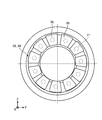
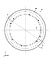
- FIG. 4 is a front view showing a schematic configuration of the thrust bearing of the present embodiment.
- FIG. 5 is a perspective view showing a part of the thrust bearing shown in FIG. 6 is a developed side view showing a part of the thrust bearing shown in FIG.
- the thrust bearing 54 is disposed so as to face a surface orthogonal to the rotation shaft 20 of the thrust collar 50, and bears a thrust load in the axial direction to restrict the movement of the thrust collar 50 in the axial direction.
- the thrust bearing 54 is a tilting pad bearing with a so-called leveling function, and includes a plurality of bearing pads (tilting pads) 70 that support a load from the thrust collar 50, a leveling mechanism 72 that supports the bearing pad 70, and a bearing. And a housing 74 for housing.
- the leveling mechanism 72 is disposed between an upper leveling plate 76 that receives a load from the bearing pad 70, a lower leveling plate 78 that receives a load from the upper leveling plate 76, and an upper leveling plate 76 and a lower leveling plate 78. And a detent pin 82 for restraining the movement of the lower leveling plate 78 relative to the housing 74.
- the plurality of bearing pads 70 have the same shape, and are arranged symmetrically with respect to the rotation axis C at equal intervals in the circumferential direction (circumferential direction) about the rotation axis 20 at positions facing the thrust collar 50. .
- Lubricating oil is supplied to the bearing pad 70 from the lubricating oil supply mechanism 41, and a lubricating oil film is formed on the surface facing the thrust collar 50. Thereby, a lubricating oil film is formed between the bearing pad 70 and the thrust collar 50, and friction generated between the thrust collar 50 and the bearing pad 70 when the thrust collar 50 rotates can be reduced.
- the bearing pad 70 has a pivot 71 near the center of the surface opposite to the surface facing the thrust collar 50, that is, the surface facing the upper leveling plate 76.
- the pivot 71 is a convex spherical support and contacts the upper leveling plate 76.
- the bearing pad 70 can be tilted with respect to the upper leveling plate 76 around the pivot 71 by contacting the upper leveling plate 76 via the pivot 71.
- a follow-up preventing means similar to a detent pin 82 described later is provided between the bearing pad 70 and the upper leveling plate 76.
- the housing 74 is a support member, a support structure, or a support base that receives a load from the thrust collar 50 to the bearing pad 70 and receives the load transmitted through the upper leveling plate 76, the connection pin 80, and the lower leveling plate 78. is there.
- the housing 74 is a member located on a surface opposite to the surface facing the thrust collar 50 in the axial direction.
- the adjustment liner 60 is fixed to the housing 74 from the upstream side in the axial direction.
- the leveling mechanism 72 is disposed between the bearing pad 70 and the housing 74, and has an upper leveling plate 76 and a lower leveling plate 78.
- the upper leveling plate 76 and the lower leveling plate 78 are alternately arranged in the circumferential direction of the rotating shaft 20.
- the lower leveling plate 78 has a pivot 84 at the center of the surface on the housing 74 side.
- the pivot 84 is a convex spherical support and is in contact with the housing 74.
- the lower leveling plate 78 is freely tiltable about the contact point of the pivot 84 with the upper surface of the housing 74.
- the leveling mechanism 72 has a connection pin 80 between the upper leveling plate 76 and the lower leveling plate 78.
- the upper leveling plate 76 and the lower leveling plate 78 are respectively provided with load receiving protrusions 76a and 78a at the ends of the rotating shaft 20 in the rotational direction.
- the connection pin 80 has a cylindrical shape, and is disposed between the load receiving protrusions 76a and 78a of the upper leveling plate 76 and the lower leveling plate 78 so that the radial direction is the axial direction of the cylinder.
- the upper leveling plates 76, the connection pins 80, and the lower leveling plates 78 are arranged symmetrically about the rotating shaft 20.
- a concave hole 78 b is formed in the lower surface of the lower leveling plate 78, and a detent pin 82 having a shape that enters the concave hole 78 b is provided in the housing 74.
- the load from the bearing pad 70 is transmitted to the housing 74 via the pivot 71, the upper leveling plate 76, the connection pin 80, the lower leveling plate 78, and the pivot 84.
- the thrust bearing 54 receives the load from the thrust collar 50 by the bearing pad 70 and regulates the axial position of the thrust collar 50.
- the thrust bearing 54 is a slide bearing, and the bearing pad 70 supports the thrust collar 50 in a state where it does not rotate in the axial direction even when the thrust collar 50 rotates.
- the upper leveling plate 76 and the lower leveling plate 78 are combined in the circumferential direction by the combination of the upper leveling plate 76, the connection pin 80, and the lower leveling plate 78, and the position of the bearing pad 70 is adjusted.
- the load on the bearing pad 70 can be equalized in the circumferential direction of the rotating shaft 20.
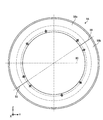
- FIG. 7 is a front view illustrating a schematic configuration of the adjustment liner according to the first support mechanism of the present embodiment.
- FIG. 8 is a side view showing a schematic configuration of the adjustment liner shown in FIG. 7.
- FIG. 9 is a front view illustrating a schematic configuration of the adjustment liner according to the second support mechanism of the present embodiment.
- FIG. 10 is a side view illustrating a schematic configuration of the adjustment liner illustrated in FIG. 9.
- FIG. 11 is an explanatory diagram for explaining the function of the thrust bearing mechanism of the present embodiment.
- FIG. 12 is an explanatory diagram for explaining the function of the thrust bearing mechanism of the comparative example.
- the support mechanism 56 has a structure in which two adjustment liners (first support mechanism) 58 and an adjustment liner (second support mechanism) 60 are used in combination.
- the two adjustment liners 58 and 60 may have the same shape, but have different attachment methods. That is, when the thrust bearings 52 and 54 are attached in the casing 24, it is necessary to attach the adjustment liners 58 and 60 so that the thickness change directions in the radial direction are opposite to each other in accordance with the inclination of the shaft. Even when the shaft is inclined, the casing 24 in which the thrust bearings 52 and 54 are accommodated always maintains a horizontal plane (levelness).
- the axial downstream end surface that supports the thrust bearing 52 in the axial direction is a surface orthogonal to the horizontal plane
- the axial upstream end surface that supports the thrust bearing 54 in the axial direction is the horizontal plane. It becomes a plane orthogonal to The structure of the adjustment liner will be described below, including the difference in the adjustment liner.
- the adjustment liner 58 is disposed on the axially downstream surface of the thrust bearing 52 and is fixed to the thrust bearing 52.
- the adjustment liner 58 is in contact with the casing 24 on the downstream surface in the axial direction.
- the adjustment liner 58 has axial end portions in contact with the thrust bearing 52 and the casing 24, respectively, so that the axial position of the thrust bearing 52 with respect to the casing 24 is a predetermined position.
- the adjustment liner 58 is formed in an annular shape around the rotation shaft 20, and passes through the rotation shaft center C from one circumferential end surface in the radial direction toward the other circumferential end surface.
- the thickness varies uniformly along the line connecting the circumferential end faces on both sides in the radial direction.
- the adjustment liner 58 is a member divided into two members, an annular member 58a and an annular member 58b, in the circumferential direction.
- the adjustment liner 58 is formed into one ring shape as a whole by arranging the divided surfaces 59 that are surfaces formed in the radial direction of the two annular members 58a and 58b in contact with each other.
- the dividing surface 59 is at a position inclined by a predetermined angle with respect to the horizontal direction (direction parallel to the horizontal plane of the casing 24) 90. Thereby, at the time of attachment, it can make it easy to mount
- the adjustment liner 58 passes from the one circumferential end surface in the radial direction toward the other circumferential end surface, passes through the rotation axis C, and extends along a line connecting the circumferential end surfaces on both radial sides.
- the thickness changes.
- the adjustment liner 58 has a shape that increases in thickness from the upper side in the radial direction to the lower side in the radial direction on the paper surface of FIG. 8, and the thickness (minimum thickness) L1 of the circumferential end surface on the upper side in the radial direction
- the relationship with the thickness (maximum thickness) L2 of the circumferential end surface on the lower side in the radial direction is L1 ⁇ L2.
- the adjustment liner 58 has an end face 58m facing the downstream side perpendicular to the horizontal plane of the casing 24 and an end face 58n facing the upstream side inclined with respect to the plane perpendicular to the horizontal plane of the casing 24.
- the end surface 58 m is an end surface on the downstream side in the axial direction of the adjustment liner 58.
- the end face 58n is an end face on the upstream side in the axial direction of the adjustment liner 58.
- the end surface 58m facing the downstream side is in contact with the surface perpendicular to the horizontal plane of the casing 24.
- an end surface 58 n facing the upstream side inclined with respect to a surface perpendicular to the horizontal plane of the casing 24 is fixed to the thrust bearing 52. Accordingly, the surfaces of the thrust bearing 52 facing the upstream side and the downstream side in the axial direction can have a direction inclined with respect to the horizontal plane of the casing 24.
- the adjustment liner 60 is disposed on the axially upstream surface of the thrust bearing 54 and is fixed to the thrust bearing 54 from the axial direction.
- the adjustment liner 60 is in contact with the casing 24 on the upstream surface in the axial direction.
- the adjustment liner 60 has axial end surfaces 60m and 60n that are in contact with the thrust bearing 54 and the casing 24, respectively, so that the axial position of the thrust bearing 54 with respect to the casing 24 is set to a predetermined position.
- the adjustment liner 60 is formed in an annular shape around the rotation shaft 20, and passes through the rotation shaft center C from one circumferential end surface in the radial direction toward the other circumferential end surface.
- the thickness varies uniformly along the line connecting the circumferential end faces on both sides in the radial direction.
- the adjustment liner 60 is a member that is divided into two members, an annular member 60a and an annular member 60b, in the circumferential direction.
- the adjustment liner 60 has one ring shape as a whole by disposing the divided surfaces 61 which are the surfaces divided in the radial direction of the two annular members 60a and 60b in contact with each other.
- the dividing surface 61 is at a position inclined by a predetermined angle with respect to the horizontal direction (direction parallel to the horizontal plane of the casing) 90. Thereby, at the time of attachment, it can make it easy to mount
- the adjustment liner 60 passes from the one circumferential end surface in the radial direction toward the other circumferential end surface, passes through the rotation axis C, and extends along a line connecting the circumferential end surfaces on both radial sides.
- the thickness changes.
- the adjustment liner 60 has a shape in which the thickness becomes thinner from the upper side in the radial direction to the lower side in the radial direction on the paper surface of FIG. 10, and the thickness (maximum thickness) L3 of the circumferential end surface on the upper side in the radial direction
- the relationship with the thickness (minimum thickness) L4 of the circumferential end surface on the lower side in the radial direction is L4 ⁇ L3.
- the adjustment liner 60 has an end surface 60n facing the upstream side parallel to a surface perpendicular to the horizontal plane of the casing 24, and an end surface 60m facing the downstream side, which is inclined with respect to a plane perpendicular to the horizontal plane of the casing 24. .
- the end surface 60 m is an end surface on the downstream side in the axial direction of the adjustment liner 60.
- the end surface 60n is an upstream end surface of the adjustment liner 60 in the axial direction.
- the adjustment liner 60 has an end surface 60n facing the upstream side in contact with a surface perpendicular to the horizontal plane of the casing 24, and an end surface 60m facing the downstream side is a surface inclined with respect to a plane perpendicular to the horizontal plane of the casing 24. It is fixed to a thrust bearing 54 to be formed. Accordingly, the end surfaces of the thrust bearing 54 facing the upstream side and the downstream side in the axial direction can be inclined with respect to the horizontal plane of the casing 24.
- the thrust bearing mechanism (rotating shaft support structure) 40 is mounted at the mounting positions of the two adjustment liners 58 and 60 so that the radial thickness changes along the line passing through the rotating shaft center C are opposite to each other.
- the adjustment liners 58 and 60 are arranged so that the position of the circumferential end portion having the minimum thickness L1 in the axial direction of the adjustment liner 58 matches the position of the circumferential end portion of the maximum thickness L3 of the adjustment liner 60 in the circumferential direction. Can be installed.
- the position of the circumferential end portion of the adjustment liner 58 having the maximum axial thickness L2 and the position of the circumferential end portion of the adjustment liner 60 having the minimum axial thickness L4 also coincide with each other in the circumferential direction. That is, by attaching the adjustment liners 58 and 60 in combination as described above, the surface of the adjustment liner 58 on the thrust bearing 52 side (end surface 58n facing the upstream side) and the surface of the adjustment liner 60 on the thrust bearing 54 side (downstream side) The facing end face 60m) can be inclined.
- the rotating shaft 20 bends due to thermal elongation, its own weight or the like even if it is disposed in the horizontal direction 90.
- a surface (reference surface) 94 perpendicular to the rotation shaft 20 passing through the center in the axial direction of the rotation shaft 20 of the thrust collar 50 is inclined by a predetermined angle with respect to the surface 92 perpendicular to the horizontal surface of the casing 24.
- the rotating shaft 20 inclines in the axial direction from the upstream side toward the downstream side in the radial direction.
- the thrust collar 50 is inclined in such a direction that the reference surface 94 moves to the upstream side of the rotary shaft 20 from the upper side in the radial direction toward the lower side in the radial direction with respect to the rotary shaft 20.
- the adjustment liners 58 and 60 are installed on a surface perpendicular to the horizontal surface of the casing 24, and the surfaces contacting the thrust bearings 52 and 54 are inclined in the same direction as the reference surface 94. . That is, the surfaces of the adjustment liners 58 and 60 that are in contact with the thrust bearings 52 and 54 are inclined in a direction orthogonal to the direction in which the rotary shaft 20 is inclined. Accordingly, the surfaces of the thrust bearings 52 and 54 that face the thrust collar 50 can be inclined according to the inclination of the thrust collar 50.
- the thrust bearing mechanism 40 can make the load applied from the thrust collar 50 to the thrust bearings 52, 54, specifically, the bearing pad 70, more uniform in the circumferential direction of the rotary shaft 20.
- the surface of the thrust bearings 52 and 54 that faces the thrust collar 50 is a surface that is perpendicular to the horizontal plane of the casing 24. 92, and is not parallel to the radial surface (a surface orthogonal to the axial direction) of the thrust collar 50 that faces the surface. Therefore, the load from the thrust collar 50 is concentrated on a part on the upper side in the radial direction of the thrust bearing 52 and a part on the lower side in the radial direction of the thrust bearing 54, and the load becomes nonuniform in the circumferential direction of the rotary shaft 20. .
- the thrust bearing mechanism 40 of the present embodiment can make the load applied from the thrust collar 50 to the thrust bearings 52 and 54 more uniform in the circumferential direction of the rotary shaft 20. Therefore, it is possible to prevent the load from being concentrated on a part of the thrust bearings 52 and 54, the metal temperature of some of the bearing pads 70 from rising, and the bearing from being damaged. Thereby, durability as the whole gas turbine can be improved and a life can be lengthened.
- FIG. 13 is a front view showing a schematic configuration of a modified adjustment liner.
- FIG. 14 is a side view showing a schematic configuration of the adjustment liner shown in FIG. 13.
- the adjustment liner 102 shown in FIG. 13 and FIG. 14 has a thickness that is smaller than the inclined portion 104 whose thickness changes depending on the position in the radial direction and the inclined portion 104 in the same manner as the adjustment liner described above. Regardless, the concave portions 106 having a constant thickness are alternately arranged in the circumferential direction.
- the adjustment liner 102 is alternately provided with a portion in contact with the thrust bearing and a portion not in contact with the thrust bearing depending on the position in the circumferential direction.
- the adjustment liner does not need to be in contact with the thrust bearing or the casing in the entire circumferential direction, the relative position of the thrust bearing and the casing can be set to a predetermined position, and the axis of the thrust bearing can be set horizontally. What is necessary is just to be able to incline in the direction according to inclination, such as the dead weight of the rotating shaft 20, with respect to a direction.
- the adjustment liner 102 shown in the present modification can be used for any of the support mechanisms (first support mechanism and second support mechanism). However, the mounting directions of the two adjustment liners are opposite to each other in the radial thickness change direction. It is necessary to use a combination of a set of adjusting liners attached in such a manner.
- the adjustment liner is used to incline the thrust bearing shaft with respect to the horizontal direction in accordance with the inclination of the rotating shaft 20 due to its own weight, etc., and a part of the load applied to the thrust bearing from the thrust collar.
- the mechanism for adjusting the position is not limited to this.
- the support mechanism only needs to be able to incline the surface in contact with the thrust collar of the thrust bearing in a predetermined direction (the above-described direction) with respect to the surface perpendicular to the horizontal plane of the casing, and various mechanisms can be used. .
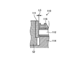
- FIG. 15 is a sectional view showing a schematic configuration of a thrust bearing mechanism of another embodiment.
- 16 is an enlarged cross-sectional view of the support mechanism of the thrust bearing mechanism shown in FIG.
- the support mechanism 110 shown in FIGS. 15 and 16 includes an adjustment liner 111 and a bolt 112.
- the adjustment liner 111 is a ring-shaped member having a constant thickness.
- the bolt 112 is inserted into a bolt hole 116 formed in the casing 114.
- a plurality of bolts 112 and bolt holes 116 are arranged at predetermined intervals in the circumferential direction.
- the bolt 112 and the bolt hole 116 serve as an adjustment mechanism that adjusts the direction of the thrust bearing 52.
- the end of the bolt 112 on the adjustment liner 111 side protrudes toward the adjustment liner 111 from the casing 114, and the protruding end contacts the adjustment liner 111.
- the end on the adjustment liner 111 side protrudes from the casing 114 to the adjustment liner 111 side by a distance L5.
- the support mechanism 110 can change the amount of the bolt 112 protruding in the axial direction from the casing 114 depending on the position in the circumferential direction or the radial direction. As a result, it is possible to adjust the orientation, that is, the inclination of the adjustment liner 111 with which the bolt 112 is in contact with the plane perpendicular to the horizontal plane of the casing 114.
- the support mechanism 110 adjusts the direction of the adjustment liner 111 according to the amount of movement of the bolt 112 in the axial direction so that the thrust bearing 52 is inclined with respect to the plane perpendicular to the horizontal plane of the casing 114. Can do.
- the thrust bearing can be inclined in the same manner as described above.
- the adjustment liner 111 is disposed.
- the bolt 112 may be brought into contact with the axially downstream surface of the thrust bearing 52 without providing the adjustment liner 111.
- the support mechanism 110 can adjust the inclination by changing the protruding movement amount depending on the circumferential position of the bolt 112, the adjustment can be easily performed.
- the support mechanism 110 shown in the present embodiment in order for the support mechanism 110 shown in the present embodiment to function, the support mechanism 110 disposed on the downstream side in the axial direction with the thrust collar 50 interposed therebetween is supported on the upstream side in the axial direction. 120 must be provided.
- the support mechanism 120 may have the same structure as the support mechanism 110, but the bolt 122 corresponding to the bolt 112 needs to be in contact with the adjustment liner 121 from the upstream side in the axial direction toward the downstream side.
- the bolt 122 is inserted into a bolt hole formed in the casing 124.
- the two support mechanisms 110 and 120 are combined as a set of support mechanisms, and are arranged with the thrust collar 50 interposed therebetween, and the inclinations of the surfaces of the adjustment liners 111 and 121 where the bolts 112 and 122 contact are opposite to each other in the radial direction. It may be used by adjusting so that.
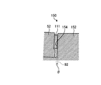
- FIG. 17 is a cross-sectional view showing a schematic configuration of a thrust bearing mechanism of another embodiment.
- a support mechanism 150 illustrated in FIG. 17 includes an adjustment liner 111 and an end surface 154 on the upstream side in the axial direction of the casing 152.
- the adjustment liner 111 is a ring-shaped member having a constant thickness.
- the end surface 154 of the casing 152 is a surface that contacts the adjustment liner 111, that is, a surface that faces the thrust bearing 52.
- the end face 154 is inclined at an angle ⁇ with respect to a plane perpendicular to the horizontal plane of the casing 152.
- the support mechanism 150 inclines the end surface 154 of the casing 152 at an angle ⁇ with respect to the surface 92 perpendicular to the horizontal plane of the casing 152, so that the adjustment liner 111 and the thrust bearing 52 that are in contact with the end surface 154
- the angle ⁇ can be inclined with respect to the direction perpendicular to the horizontal plane.
- the angle ⁇ is an inclination angle similar to that in the above-described embodiment.
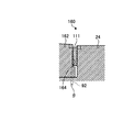
- FIG. 18 is a cross-sectional view showing a schematic configuration of a thrust bearing mechanism of another embodiment.
- a support mechanism 160 illustrated in FIG. 18 includes an adjustment liner 111 and an end surface 164 of the thrust bearing 162.
- the adjustment liner 111 is a ring-shaped member having a constant thickness.
- the end surface 164 of the thrust bearing 162 is a surface that contacts the adjustment liner 111, that is, a surface that faces the adjustment liner 111.
- the end surface 164 is inclined at an angle ⁇ with respect to a direction perpendicular to the horizontal plane of the casing 24.
- the support mechanism 160 inclines the end surface 164 of the thrust bearing 162 at an angle ⁇ with respect to the surface 92 perpendicular to the horizontal plane of the casing 24, so that the adjustment liner 111 and the thrust bearing 162 that are in contact with the end surface 164 are connected to the casing 24.
- Even the plane parallel to the plane 92 perpendicular to the horizontal plane of the thrust bearing 162 can be inclined by the angle ⁇ .
- the angle ⁇ is an inclination angle similar to that in the above-described embodiment.
- support mechanisms having the same structure are arranged on the upstream and downstream sides in the axial direction with the thrust collar interposed therebetween. It may be used as a set of support mechanisms.
- the adjustment liners disposed on the upstream side and the downstream side in the axial direction with the thrust collar interposed therebetween may be disposed so that the inclinations are opposite to each other in the radial direction.
Landscapes
- Engineering & Computer Science (AREA)
- General Engineering & Computer Science (AREA)
- Mechanical Engineering (AREA)
- Sliding-Contact Bearings (AREA)
- Support Of The Bearing (AREA)
- Chemical & Material Sciences (AREA)
- Combustion & Propulsion (AREA)
- Mounting Of Bearings Or Others (AREA)
Abstract
Priority Applications (4)
| Application Number | Priority Date | Filing Date | Title |
|---|---|---|---|
| CN201380074723.XA CN105190061B (zh) | 2013-03-19 | 2013-10-21 | 旋转轴支承结构 |
| DE112013006848.6T DE112013006848T5 (de) | 2013-03-19 | 2013-10-21 | Lagerstruktur einer rotierenden Welle |
| US14/777,144 US9759255B2 (en) | 2013-03-19 | 2013-10-21 | Rotating shaft support structure |
| KR1020157025362A KR101682847B1 (ko) | 2013-03-19 | 2013-10-21 | 회전축 지지 구조 |
Applications Claiming Priority (2)
| Application Number | Priority Date | Filing Date | Title |
|---|---|---|---|
| JP2013057294A JP6222952B2 (ja) | 2013-03-19 | 2013-03-19 | 回転軸支持構造 |
| JP2013-057294 | 2013-03-19 |
Publications (1)
| Publication Number | Publication Date |
|---|---|
| WO2014147878A1 true WO2014147878A1 (fr) | 2014-09-25 |
Family
ID=51579590
Family Applications (1)
| Application Number | Title | Priority Date | Filing Date |
|---|---|---|---|
| PCT/JP2013/078451 WO2014147878A1 (fr) | 2013-03-19 | 2013-10-21 | Structure de support d'arbre rotatif |
Country Status (6)
| Country | Link |
|---|---|
| US (1) | US9759255B2 (fr) |
| JP (1) | JP6222952B2 (fr) |
| KR (1) | KR101682847B1 (fr) |
| CN (1) | CN105190061B (fr) |
| DE (1) | DE112013006848T5 (fr) |
| WO (1) | WO2014147878A1 (fr) |
Cited By (1)
| Publication number | Priority date | Publication date | Assignee | Title |
|---|---|---|---|---|
| CN110056571A (zh) * | 2019-05-23 | 2019-07-26 | 中国船舶重工集团公司第七0三研究所 | 一种燃气轮机用耦合双向止推油膜阻尼器支承系统 |
Families Citing this family (12)
| Publication number | Priority date | Publication date | Assignee | Title |
|---|---|---|---|---|
| US9523462B2 (en) * | 2014-05-15 | 2016-12-20 | Andritz Inc. | Adjustment housing assembly and monitoring and support system for a rotary feeder in a cellulose chip feeding system for a continuous digester |
| KR101891677B1 (ko) * | 2016-11-17 | 2018-08-24 | 두산중공업 주식회사 | 개선된 틸팅 패드 스러스트 베어링 |
| CN107061490A (zh) * | 2017-05-22 | 2017-08-18 | 哈尔滨电气动力装备有限公司 | 金属瓦块水润滑摩擦副结构 |
| CN107642542B (zh) * | 2017-09-25 | 2024-01-09 | 台州七八一六船舶工业有限公司 | 一种高速止推滑动轴承 |
| JP6954857B2 (ja) * | 2018-03-08 | 2021-10-27 | 三菱重工業株式会社 | 過給機 |
| KR102090145B1 (ko) * | 2018-08-30 | 2020-03-17 | 두산중공업 주식회사 | 스러스트 베어링 및 터빈 발전 시스템 및 그 제어방법 |
| CN109236851B (zh) * | 2018-10-09 | 2023-12-22 | 中国船舶重工集团公司第七0三研究所 | 轴向串联双推力自平衡滑动轴承 |
| JP7131334B2 (ja) * | 2018-11-29 | 2022-09-06 | 株式会社安川電機 | 基板支持装置、基板搬送ロボットおよびアライナ装置 |
| JP6804578B2 (ja) * | 2019-02-08 | 2020-12-23 | 大同メタル工業株式会社 | 内燃機関のクランク軸用の半割スラスト軸受 |
| CN110529493A (zh) * | 2019-08-23 | 2019-12-03 | 东方电气集团东方汽轮机有限公司 | 一种均载推力轴承 |
| WO2021111543A1 (fr) * | 2019-12-04 | 2021-06-10 | 三菱重工エンジン&ターボチャージャ株式会社 | Dispositif de palier de butée et turbocompresseur |
| KR102535775B1 (ko) * | 2022-08-01 | 2023-05-26 | 김보억 | 원자력 터빈 스러스트 베어링 체결구조 |
Citations (4)
| Publication number | Priority date | Publication date | Assignee | Title |
|---|---|---|---|---|
| JPS59191418U (ja) * | 1983-06-06 | 1984-12-19 | 三菱電機株式会社 | 立形水車発電機スラスト軸受の支持装置 |
| JPH10246224A (ja) * | 1997-03-03 | 1998-09-14 | Mitsubishi Heavy Ind Ltd | スラスト軸受 |
| JP2000186712A (ja) * | 1998-12-10 | 2000-07-04 | Kingsbury Inc | 推力軸受 |
| JP2002070853A (ja) * | 2000-08-29 | 2002-03-08 | Mitsubishi Heavy Ind Ltd | 高ダンピングスラスト軸受 |
Family Cites Families (16)
| Publication number | Priority date | Publication date | Assignee | Title |
|---|---|---|---|---|
| GB191005035A (en) * | 1910-02-28 | 1911-02-23 | Sebastian Ziani De Ferranti | Improvements in and relating to Thrust Bearings and the like. |
| DE1525147C3 (de) * | 1965-07-30 | 1975-09-04 | Kugelfischer Georg Schaefer & Co, 8720 Schweinfurt | Hydrostatisches Axial-Radialtager |
| JPS5856789A (ja) | 1981-09-25 | 1983-04-04 | 松下電器産業株式会社 | ハンドリング装置 |
| JPS6046610B2 (ja) | 1983-04-14 | 1985-10-17 | 古河電気工業株式会社 | ケ−ブルのスネ−ク型水平布設装置 |
| JPH05231423A (ja) * | 1992-02-18 | 1993-09-07 | Mitsubishi Heavy Ind Ltd | ティルティングパッド型スラスト軸受 |
| JPH0663929A (ja) | 1992-08-12 | 1994-03-08 | Jiototsupu:Kk | コンクリート型枠の掃除装置 |
| JPH0663929U (ja) * | 1993-02-19 | 1994-09-09 | 三菱重工業株式会社 | スラスト軸受 |
| JP3294064B2 (ja) * | 1995-06-09 | 2002-06-17 | 三菱重工業株式会社 | スラスト軸受装置 |
| JP3564249B2 (ja) | 1996-12-09 | 2004-09-08 | 三菱重工業株式会社 | ディーゼル機関の主軸受構造 |
| JPH11315828A (ja) * | 1998-05-08 | 1999-11-16 | Mitsubishi Heavy Ind Ltd | 組み合わせすべり軸受 |
| DE19929412A1 (de) * | 1999-06-26 | 2000-12-28 | Abb Research Ltd | Lagerelement |
| JP5000044B2 (ja) * | 2001-04-17 | 2012-08-15 | 三菱重工コンプレッサ株式会社 | スラスト軸受装置 |
| JP2004084557A (ja) * | 2002-08-27 | 2004-03-18 | Mitsubishi Heavy Ind Ltd | 縦型タービン及び軸受装置 |
| JP5314517B2 (ja) * | 2009-07-06 | 2013-10-16 | 三菱重工業株式会社 | 軸受装置、軸受ユニットおよび回転機械 |
| JP2011169418A (ja) | 2010-02-19 | 2011-09-01 | Mitsubishi Heavy Ind Ltd | スラスト軸受及び回転機械並びにスラスト荷重計測方法 |
| JP5773806B2 (ja) * | 2011-08-30 | 2015-09-02 | 三菱日立パワーシステムズ株式会社 | スラスト軸受 |
-
2013
- 2013-03-19 JP JP2013057294A patent/JP6222952B2/ja active Active
- 2013-10-21 DE DE112013006848.6T patent/DE112013006848T5/de not_active Ceased
- 2013-10-21 KR KR1020157025362A patent/KR101682847B1/ko active IP Right Grant
- 2013-10-21 CN CN201380074723.XA patent/CN105190061B/zh active Active
- 2013-10-21 US US14/777,144 patent/US9759255B2/en active Active
- 2013-10-21 WO PCT/JP2013/078451 patent/WO2014147878A1/fr active Application Filing
Patent Citations (4)
| Publication number | Priority date | Publication date | Assignee | Title |
|---|---|---|---|---|
| JPS59191418U (ja) * | 1983-06-06 | 1984-12-19 | 三菱電機株式会社 | 立形水車発電機スラスト軸受の支持装置 |
| JPH10246224A (ja) * | 1997-03-03 | 1998-09-14 | Mitsubishi Heavy Ind Ltd | スラスト軸受 |
| JP2000186712A (ja) * | 1998-12-10 | 2000-07-04 | Kingsbury Inc | 推力軸受 |
| JP2002070853A (ja) * | 2000-08-29 | 2002-03-08 | Mitsubishi Heavy Ind Ltd | 高ダンピングスラスト軸受 |
Cited By (2)
| Publication number | Priority date | Publication date | Assignee | Title |
|---|---|---|---|---|
| CN110056571A (zh) * | 2019-05-23 | 2019-07-26 | 中国船舶重工集团公司第七0三研究所 | 一种燃气轮机用耦合双向止推油膜阻尼器支承系统 |
| CN110056571B (zh) * | 2019-05-23 | 2024-01-12 | 中国船舶重工集团公司第七0三研究所 | 一种燃气轮机用耦合双向止推油膜阻尼器支承系统 |
Also Published As
| Publication number | Publication date |
|---|---|
| KR20150119340A (ko) | 2015-10-23 |
| CN105190061B (zh) | 2018-03-30 |
| JP2014181774A (ja) | 2014-09-29 |
| JP6222952B2 (ja) | 2017-11-01 |
| DE112013006848T5 (de) | 2015-12-03 |
| KR101682847B1 (ko) | 2016-12-05 |
| US9759255B2 (en) | 2017-09-12 |
| US20160032963A1 (en) | 2016-02-04 |
| CN105190061A (zh) | 2015-12-23 |
Similar Documents
| Publication | Publication Date | Title |
|---|---|---|
| JP6222952B2 (ja) | 回転軸支持構造 | |
| US9890809B2 (en) | Tilting pad thrust bearing and tilting pad thrust bearing assembly | |
| CN100491700C (zh) | 燃气轮机中的定子叶片致动器 | |
| US11933276B2 (en) | Rotary slide bearing | |
| US9890810B2 (en) | Squeeze film damper, bearing unit, and turbine | |
| US20110000222A1 (en) | Gas turbine rotor-stator support system | |
| JP6783534B2 (ja) | ラジアル軸受装置、及び、回転機械 | |
| US20060078244A1 (en) | Hybrid bearing | |
| JP6820314B2 (ja) | オフセット調整式ピボットジャーナルパッド | |
| JP5936725B1 (ja) | ジャーナル軸受装置、及び、回転機械 | |
| JP6148465B2 (ja) | タービン組立体及びタービン部品を支持するための方法 | |
| JP2013029135A (ja) | ティルティングパッドジャーナル軸受および蒸気タービン | |
| US20200392986A1 (en) | Bearing pad for tilting-pad bearing, tilting-pad bearing, and rotary machine | |
| JP5922809B1 (ja) | ティルティングパッド軸受および回転機械 | |
| KR20120113241A (ko) | 가스 터빈 엔진과 포일 베어링 시스템 | |
| US20130216359A1 (en) | Compressor | |
| US9618036B2 (en) | Tilting-pad bearing | |
| JP6725438B2 (ja) | 軸受装置及び回転機械 | |
| JP5922808B1 (ja) | 軸受装置および軸受装置の据付方法 | |
| JP2019082233A (ja) | ティルティングパッド軸受 | |
| JP2016142311A (ja) | タービン | |
| KR20160078303A (ko) | 틸팅 패드 스러스트 베어링 및 틸팅 패드 스러스트 베어링 조립체 | |
| CN109185329A (zh) | 一种压缩机的曲轴轴承和压缩机 | |
| JP2017025820A (ja) | 蒸気タービンのノズルダイアフラム取り付け構造 | |
| RU161203U1 (ru) | Лепестковый газодинамический подшипниковый узел |
Legal Events
| Date | Code | Title | Description |
|---|---|---|---|
| WWE | Wipo information: entry into national phase |
Ref document number: 201380074723.X Country of ref document: CN |
|
| 121 | Ep: the epo has been informed by wipo that ep was designated in this application |
Ref document number: 13878692 Country of ref document: EP Kind code of ref document: A1 |
|
| ENP | Entry into the national phase |
Ref document number: 20157025362 Country of ref document: KR Kind code of ref document: A |
|
| WWE | Wipo information: entry into national phase |
Ref document number: 14777144 Country of ref document: US |
|
| WWE | Wipo information: entry into national phase |
Ref document number: 112013006848 Country of ref document: DE Ref document number: 1120130068486 Country of ref document: DE |
|
| 122 | Ep: pct application non-entry in european phase |
Ref document number: 13878692 Country of ref document: EP Kind code of ref document: A1 |