WO2014142244A1 - X線診断装置 - Google Patents
X線診断装置 Download PDFInfo
- Publication number
- WO2014142244A1 WO2014142244A1 PCT/JP2014/056692 JP2014056692W WO2014142244A1 WO 2014142244 A1 WO2014142244 A1 WO 2014142244A1 JP 2014056692 W JP2014056692 W JP 2014056692W WO 2014142244 A1 WO2014142244 A1 WO 2014142244A1
- Authority
- WO
- WIPO (PCT)
- Prior art keywords
- arm
- slide
- ray
- diagnostic apparatus
- ray diagnostic
- Prior art date
- Legal status (The legal status is an assumption and is not a legal conclusion. Google has not performed a legal analysis and makes no representation as to the accuracy of the status listed.)
- Ceased
Links
Images


Classifications
-
- A—HUMAN NECESSITIES
- A61—MEDICAL OR VETERINARY SCIENCE; HYGIENE
- A61B—DIAGNOSIS; SURGERY; IDENTIFICATION
- A61B6/00—Apparatus or devices for radiation diagnosis; Apparatus or devices for radiation diagnosis combined with radiation therapy equipment
- A61B6/44—Constructional features of apparatus for radiation diagnosis
- A61B6/4429—Constructional features of apparatus for radiation diagnosis related to the mounting of source units and detector units
- A61B6/4435—Constructional features of apparatus for radiation diagnosis related to the mounting of source units and detector units the source unit and the detector unit being coupled by a rigid structure
- A61B6/4441—Constructional features of apparatus for radiation diagnosis related to the mounting of source units and detector units the source unit and the detector unit being coupled by a rigid structure the rigid structure being a C-arm or U-arm
-
- A—HUMAN NECESSITIES
- A61—MEDICAL OR VETERINARY SCIENCE; HYGIENE
- A61B—DIAGNOSIS; SURGERY; IDENTIFICATION
- A61B6/00—Apparatus or devices for radiation diagnosis; Apparatus or devices for radiation diagnosis combined with radiation therapy equipment
- A61B6/04—Positioning of patients; Tiltable beds or the like
- A61B6/0407—Supports, e.g. tables or beds, for the body or parts of the body
-
- A—HUMAN NECESSITIES
- A61—MEDICAL OR VETERINARY SCIENCE; HYGIENE
- A61B—DIAGNOSIS; SURGERY; IDENTIFICATION
- A61B6/00—Apparatus or devices for radiation diagnosis; Apparatus or devices for radiation diagnosis combined with radiation therapy equipment
- A61B6/44—Constructional features of apparatus for radiation diagnosis
- A61B6/4429—Constructional features of apparatus for radiation diagnosis related to the mounting of source units and detector units
- A61B6/4464—Constructional features of apparatus for radiation diagnosis related to the mounting of source units and detector units the source unit or the detector unit being mounted to ceiling
-
- A—HUMAN NECESSITIES
- A61—MEDICAL OR VETERINARY SCIENCE; HYGIENE
- A61B—DIAGNOSIS; SURGERY; IDENTIFICATION
- A61B6/00—Apparatus or devices for radiation diagnosis; Apparatus or devices for radiation diagnosis combined with radiation therapy equipment
- A61B6/44—Constructional features of apparatus for radiation diagnosis
- A61B6/4476—Constructional features of apparatus for radiation diagnosis related to motor-assisted motion of the source unit
-
- A—HUMAN NECESSITIES
- A61—MEDICAL OR VETERINARY SCIENCE; HYGIENE
- A61B—DIAGNOSIS; SURGERY; IDENTIFICATION
- A61B6/00—Apparatus or devices for radiation diagnosis; Apparatus or devices for radiation diagnosis combined with radiation therapy equipment
- A61B6/44—Constructional features of apparatus for radiation diagnosis
- A61B6/4476—Constructional features of apparatus for radiation diagnosis related to motor-assisted motion of the source unit
- A61B6/4482—Constructional features of apparatus for radiation diagnosis related to motor-assisted motion of the source unit involving power assist circuits
-
- A—HUMAN NECESSITIES
- A61—MEDICAL OR VETERINARY SCIENCE; HYGIENE
- A61B—DIAGNOSIS; SURGERY; IDENTIFICATION
- A61B6/00—Apparatus or devices for radiation diagnosis; Apparatus or devices for radiation diagnosis combined with radiation therapy equipment
- A61B6/50—Apparatus or devices for radiation diagnosis; Apparatus or devices for radiation diagnosis combined with radiation therapy equipment specially adapted for specific body parts; specially adapted for specific clinical applications
- A61B6/501—Apparatus or devices for radiation diagnosis; Apparatus or devices for radiation diagnosis combined with radiation therapy equipment specially adapted for specific body parts; specially adapted for specific clinical applications for diagnosis of the head, e.g. neuroimaging or craniography
-
- A—HUMAN NECESSITIES
- A61—MEDICAL OR VETERINARY SCIENCE; HYGIENE
- A61B—DIAGNOSIS; SURGERY; IDENTIFICATION
- A61B6/00—Apparatus or devices for radiation diagnosis; Apparatus or devices for radiation diagnosis combined with radiation therapy equipment
- A61B6/50—Apparatus or devices for radiation diagnosis; Apparatus or devices for radiation diagnosis combined with radiation therapy equipment specially adapted for specific body parts; specially adapted for specific clinical applications
- A61B6/504—Apparatus or devices for radiation diagnosis; Apparatus or devices for radiation diagnosis combined with radiation therapy equipment specially adapted for specific body parts; specially adapted for specific clinical applications for diagnosis of blood vessels, e.g. by angiography
-
- A—HUMAN NECESSITIES
- A61—MEDICAL OR VETERINARY SCIENCE; HYGIENE
- A61B—DIAGNOSIS; SURGERY; IDENTIFICATION
- A61B6/00—Apparatus or devices for radiation diagnosis; Apparatus or devices for radiation diagnosis combined with radiation therapy equipment
- A61B6/52—Devices using data or image processing specially adapted for radiation diagnosis
- A61B6/5211—Devices using data or image processing specially adapted for radiation diagnosis involving processing of medical diagnostic data
- A61B6/5229—Devices using data or image processing specially adapted for radiation diagnosis involving processing of medical diagnostic data combining image data of a patient, e.g. combining a functional image with an anatomical image
- A61B6/5235—Devices using data or image processing specially adapted for radiation diagnosis involving processing of medical diagnostic data combining image data of a patient, e.g. combining a functional image with an anatomical image combining images from the same or different ionising radiation imaging techniques, e.g. PET and CT
-
- F—MECHANICAL ENGINEERING; LIGHTING; HEATING; WEAPONS; BLASTING
- F16—ENGINEERING ELEMENTS AND UNITS; GENERAL MEASURES FOR PRODUCING AND MAINTAINING EFFECTIVE FUNCTIONING OF MACHINES OR INSTALLATIONS; THERMAL INSULATION IN GENERAL
- F16C—SHAFTS; FLEXIBLE SHAFTS; ELEMENTS OR CRANKSHAFT MECHANISMS; ROTARY BODIES OTHER THAN GEARING ELEMENTS; BEARINGS
- F16C19/00—Bearings with rolling contact, for exclusively rotary movement
- F16C19/50—Other types of ball or roller bearings
- F16C19/502—Other types of ball or roller bearings with rolling elements in rows not forming a full circle
-
- A—HUMAN NECESSITIES
- A61—MEDICAL OR VETERINARY SCIENCE; HYGIENE
- A61B—DIAGNOSIS; SURGERY; IDENTIFICATION
- A61B6/00—Apparatus or devices for radiation diagnosis; Apparatus or devices for radiation diagnosis combined with radiation therapy equipment
- A61B6/04—Positioning of patients; Tiltable beds or the like
- A61B6/0487—Motor-assisted positioning
-
- A—HUMAN NECESSITIES
- A61—MEDICAL OR VETERINARY SCIENCE; HYGIENE
- A61B—DIAGNOSIS; SURGERY; IDENTIFICATION
- A61B6/00—Apparatus or devices for radiation diagnosis; Apparatus or devices for radiation diagnosis combined with radiation therapy equipment
- A61B6/44—Constructional features of apparatus for radiation diagnosis
- A61B6/4429—Constructional features of apparatus for radiation diagnosis related to the mounting of source units and detector units
- A61B6/4435—Constructional features of apparatus for radiation diagnosis related to the mounting of source units and detector units the source unit and the detector unit being coupled by a rigid structure
- A61B6/4447—Tiltable gantries
-
- A—HUMAN NECESSITIES
- A61—MEDICAL OR VETERINARY SCIENCE; HYGIENE
- A61B—DIAGNOSIS; SURGERY; IDENTIFICATION
- A61B6/00—Apparatus or devices for radiation diagnosis; Apparatus or devices for radiation diagnosis combined with radiation therapy equipment
- A61B6/48—Diagnostic techniques
- A61B6/481—Diagnostic techniques involving the use of contrast agents
-
- F—MECHANICAL ENGINEERING; LIGHTING; HEATING; WEAPONS; BLASTING
- F16—ENGINEERING ELEMENTS AND UNITS; GENERAL MEASURES FOR PRODUCING AND MAINTAINING EFFECTIVE FUNCTIONING OF MACHINES OR INSTALLATIONS; THERMAL INSULATION IN GENERAL
- F16C—SHAFTS; FLEXIBLE SHAFTS; ELEMENTS OR CRANKSHAFT MECHANISMS; ROTARY BODIES OTHER THAN GEARING ELEMENTS; BEARINGS
- F16C2316/00—Apparatus in health or amusement
- F16C2316/10—Apparatus in health or amusement in medical appliances, e.g. in diagnosis, dentistry, instruments, prostheses, medical imaging appliances
-
- F—MECHANICAL ENGINEERING; LIGHTING; HEATING; WEAPONS; BLASTING
- F16—ENGINEERING ELEMENTS AND UNITS; GENERAL MEASURES FOR PRODUCING AND MAINTAINING EFFECTIVE FUNCTIONING OF MACHINES OR INSTALLATIONS; THERMAL INSULATION IN GENERAL
- F16C—SHAFTS; FLEXIBLE SHAFTS; ELEMENTS OR CRANKSHAFT MECHANISMS; ROTARY BODIES OTHER THAN GEARING ELEMENTS; BEARINGS
- F16C29/00—Bearings for parts moving only linearly
- F16C29/04—Ball or roller bearings
- F16C29/06—Ball or roller bearings in which the rolling bodies circulate partly without carrying load
- F16C29/0633—Ball or roller bearings in which the rolling bodies circulate partly without carrying load with a bearing body defining a U-shaped carriage, i.e. surrounding a guide rail or track on three sides
- F16C29/0635—Ball or roller bearings in which the rolling bodies circulate partly without carrying load with a bearing body defining a U-shaped carriage, i.e. surrounding a guide rail or track on three sides whereby the return paths are provided as bores in a main body of the U-shaped carriage, e.g. the main body of the U-shaped carriage is a single part with end caps provided at each end
- F16C29/0638—Ball or roller bearings in which the rolling bodies circulate partly without carrying load with a bearing body defining a U-shaped carriage, i.e. surrounding a guide rail or track on three sides whereby the return paths are provided as bores in a main body of the U-shaped carriage, e.g. the main body of the U-shaped carriage is a single part with end caps provided at each end with balls
- F16C29/0642—Ball or roller bearings in which the rolling bodies circulate partly without carrying load with a bearing body defining a U-shaped carriage, i.e. surrounding a guide rail or track on three sides whereby the return paths are provided as bores in a main body of the U-shaped carriage, e.g. the main body of the U-shaped carriage is a single part with end caps provided at each end with balls with four rows of balls
- F16C29/0647—Ball or roller bearings in which the rolling bodies circulate partly without carrying load with a bearing body defining a U-shaped carriage, i.e. surrounding a guide rail or track on three sides whereby the return paths are provided as bores in a main body of the U-shaped carriage, e.g. the main body of the U-shaped carriage is a single part with end caps provided at each end with balls with four rows of balls with load directions in X-arrangement
Definitions
- Embodiments of the present invention relate to an X-ray diagnostic apparatus.
- the X-ray generator and the X-ray detector are held by the C-arm in a state of facing each other.
- an X-ray diagnostic apparatus that drives a pair of X-ray generation units and an X-ray detector using a plurality of arms has been proposed.
- first arc-shaped arm and the second arc-shaped arm are slidably arranged on a support base that can rotate around the first rotation axis, and can be slid, respectively.
- An X-ray diagnostic apparatus having a structure in which the end of the third arc-shaped arm holding the detector on the X-ray detector side is attached to a second rotating shaft provided on the second arc-shaped arm is proposed. Has been.
- the X-ray diagnostic apparatus in addition to the horizontal or vertical first rotation axis fixed to the support base, two rotation axes parallel to the X-ray irradiation direction are used.
- the X-ray generator and the X-ray detector can be positioned. Further, the X-ray generator and the X-ray detector can be positioned by the sliding operations of the first arc-shaped arm and the second arc-shaped arm.
- a second rotating shaft is attached to one end of a first arc-shaped arm that is suspended on the ceiling so that it can rotate around the first rotating shaft and slides along an arc-shaped track.
- an X-ray diagnostic apparatus having a structure in which a substantially central part of a second arc-shaped arm holding an X-ray generator and an X-ray detector at both ends is attached to a second rotating shaft.
- the X-ray generator and the X-ray detector are positioned by the first rotating shaft fixed to the ceiling, the sliding motion of the first arc-shaped arm, and the second rotating shaft. It can be carried out.
- X-ray diagnostic apparatuses are desired to be able to perform imaging from various directions such as 3D (3D) imaging and imaging of blood vessels running diagonally.
- an object of the present invention is to provide an X-ray diagnostic apparatus capable of easily performing a wide variety of imaging such as 3D imaging and imaging of blood vessels traveling obliquely.
- An X-ray diagnostic apparatus includes a first arm, a second arm, a holding unit, and an imaging system.
- the first arm rotates about the first rotation axis and slides relative to the first rotation axis along the arc-shaped first slide axis.
- the second arm rotates around the second rotation axis and slides relative to the second rotation axis along the arcuate second slide axis.
- the holding unit is connected to the first arm side and holds the second arm.
- the imaging system includes an X-ray generator and an X-ray detector attached to the second arm.
- An X-ray diagnostic apparatus includes an arm, a rotation shaft, and an imaging system.
- At least one arm slides along an arcuate slide axis by a slide guide mechanism having a holding structure in which a plurality of spheres roll on an arcuate rail.
- the rotating shaft rotates the or other arm.
- the imaging system includes an X-ray generator and an X-ray detector attached to the aforementioned or other arm.
- An X-ray diagnostic apparatus includes a plurality of arms, an imaging system, and a control system. At least one of the plurality of arms slides along an arcuate slide axis, and at least one of the arms rotates around the rotation axis.
- the imaging system includes an X-ray generator and an X-ray detector attached to at least one of the plurality of arms.
- the control system images the subject by controlling the plurality of arms and the imaging system. Further, the control system simultaneously starts the movement of the plurality of arms at the time of starting the movement of the imaging system, and the first mode for starting and stopping the movement of the plurality of arms independently. At the time of stopping, the plurality of arms and the photographing system can be controlled by switching to the second mode in which the plurality of arms are simultaneously stopped.
- the X-ray diagnostic apparatus includes a first arm, a holding unit, and a second arm.
- the first arm slides along an arcuate slide axis and holds the X-ray generation unit and the X-ray detector.
- the holding unit holds the first arm so as to be slidable.
- the second arm slidably holds the holding portion and is attached to at least one of the ceiling, the floor, and the wall.
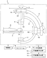
- FIG. 1 is a configuration diagram of an X-ray diagnostic apparatus according to an embodiment of the present invention.
- the figure which shows the example which made the C-type arm main rotating shaft shown in FIG. 1 incline according to the body axis of a subject.
- FIG. 1 is a configuration diagram of an X-ray diagnostic apparatus according to an embodiment of the present invention.
- the X-ray diagnostic apparatus 1 includes a first arm 2, a first rotating shaft 3, a second arm 4, a second rotating shaft 5, an imaging system 6, a bed 7, a control system 8, a console 9, and a data processing system. 10 is provided.
- the imaging system 6 includes an X-ray generator 11 and an X-ray detector 12.
- the data processing system 10 also includes a two-dimensional (2D) image generating unit 13 and a 3D image generating unit 14.
- the first arm 2 can be rotated around the first rotation shaft 3. Moreover, the 1st arm 2 can be attached to a ceiling by using the 1st rotating shaft 3 as a support
- the support arm 2 is configured to be able to slide relative to the support pivot axis 3 along the arc-shaped first slide axis S ⁇ b> 1 by the first slide mechanism 15. Therefore, the shape of the support arm 2 can also be an arc.
- the first slide shaft S1 is referred to as a column-side arc slide shaft S1
- the first slide mechanism 15 is referred to as a column-side arm slide mechanism 15.
- the second arm 4 can be rotated around the second rotating shaft 5.
- An imaging system 6 is attached to the second arm 4.
- an X-ray generation unit 11 having an X-ray tube for irradiating X-rays toward the subject O is fixed to one end of the second arm 4
- An X-ray detector 12 is fixed to the other end of the arm 4 so as to face the X-ray generation unit 11 with the subject O set on the bed 7 interposed therebetween. Therefore, the shape of the second arm 4 is C-shaped. Therefore, hereinafter, the second arm 4 is referred to as a C-type arm 4, and the second rotation shaft 5 is referred to as a C-type arm main rotation shaft 5.
- the C-arm 4 is configured to be able to slide relative to the C-arm main rotary shaft 5 along the arc-shaped second slide axis S2 by the second slide mechanism 16.
- the 2nd slide mechanism 16 is connected with the support
- a holding unit that is connected to the support arm 2 side and holds the C-arm 4 may be provided.
- the second slide shaft S2 is referred to as a C-type arm slide shaft S2
- the second slide mechanism 16 is referred to as a C-type arm slide mechanism 16.
- the C-arm 4 can be rotated like a propeller by the C-arm main rotary shaft 5 with the desired position of the C-arm 4 as a rotation axis.
- the C-type arm main rotation shaft 5 functions as a rotation mechanism that rotates the C-type arm 4 about the second rotation shaft 5 as a center line.
- a C-arm main rotation shaft 5 as a rotation mechanism for rotating the C-arm 4 is fixed to the support arm 2. Therefore, the C-arm main rotary shaft 5 itself can be moved along with the C-arm 4 along the support-side arc slide shaft S1. In addition, the C-type arm 4 and the C-type main arm rotation shaft 5 can be rotated around the support column turning shaft 3 together with the support column side arm 2. For this reason, it is possible to incline the C-type arm 4 and the C-type main arm rotation shaft 5 at an arbitrary angle.
- the attachment position of the C-arm main rotary shaft 5 to the support-side arm 2 is such that the end of the support-side arm 2 is an obstacle to peripheral equipment and causes interference to prevent interference. The end of the arm 2 is desirable.
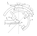
- FIG. 2 is a view showing an example in which the C-arm main rotating shaft 5 shown in FIG. 1 is inclined according to the imaging section of the subject O.
- FIG. 2 is a view showing an example in which the C-arm main rotating shaft 5 shown in FIG. 1 is inclined according to the imaging section of the subject O.
- the C-arm main rotary shaft 5 can be inclined at an arbitrary angle as shown in FIG. For this reason, even if the blood vessel B running obliquely with respect to the horizontal direction in the imaging region such as the brain or the heart is a treatment target, the C-type is parallel to the running direction of the blood vessel B running obliquely.
- the arm main rotating shaft 5 can be positioned.
- the C-arm 4 can be rotated like a propeller around the isocenter (treatment center) axis with the C-arm main rotating shaft 5 set in a direction perpendicular to the cross section of the oblique blood vessel B. it can. That is, the X-ray generator 11 and the X-ray detector 12 are arranged so that the locus is circular around the isocenter axis inclined with respect to the body axis of the subject O by the rotation of the C-arm main rotary shaft 5.
- the imaging system 6 including it can be rotated. Thereby, it is possible to take an X-ray image that allows easy observation of the form in the inclined region of interest such as the blood vessel B that runs obliquely.
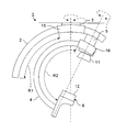
- FIG. 3 is a diagram showing an example in which the C-arm main rotating shaft 5 shown in FIG. 1 is tilted according to the body axis of the subject O.
- the C-arm main rotary shaft 5 is not limited to the imaging section of the subject O, but can be inclined according to the body axis of the subject O.
- the C-arm main rotary shaft 5 can be inclined in accordance with the body axis of the subject O.
- the bed 7 for setting the subject O is tilted according to the tilt direction of the C-arm main rotary shaft 5 so that the carbon dioxide gas as the contrast agent is sufficiently supplied to the imaging region of the subject O. Can be made.
- the C-arm main rotary shaft 5 is tilted in accordance with the tilt angle of the bed 7. Can be made. Then, it is possible to perform 3D imaging by rotating the C-arm 4 together with the imaging system 6 like a propeller.
- the C-type arm 4 can be rotated around the C-type main arm rotation axis 5 that is inclined by the movement of the support arm 2.
- the column-side arc slide shaft S1 and the C-type arm slide shaft S2 are on the same plane by the rotation operation of the column turning shaft 3 and the C-type arm main rotation shaft 5, the column-side arc slide axis S1 is provided. And the C-shaped arm slide shaft S2 are concentric. For this reason, the range of the angle at which the C-type arm 4 can turn in the same plane can be set to a range obtained by adding the movable range of the column-side arm slide mechanism 15 to the movable range of the C-type arm slide mechanism 16. As a result, the imaging system 6 can be tilted over an angle range of 180 degrees or more for 3D imaging.
- the column-side arm slide mechanism 15 for sliding the column-side arm 2 along the column-side arc slide axis S1 and the C-type arm slide mechanism 16 for sliding the C-type arm 4 along the C-type arm slide axis S2 are used. Any structure can be adopted. Typically, a slide guide mechanism in which a cylindrical wheel runs on a rail curved in an arc shape can be used for one or both of the support arm slide mechanism 15 and the C-arm slide mechanism 16.
- the support side arm slide mechanism 15 is loaded with the imaging system 6, the C-type arm 4, the C-type main arm rotation shaft 5, and the support side arm 2. Therefore, the strut-side arm slide mechanism 15 has a structure with high rigidity, which leads to an improvement in image quality by suppressing vibration.
- FIG. 4 is a perspective view showing an example of a slide mechanism that can be adopted as the support arm slide mechanism 15 and the C-arm slide mechanism 16 shown in FIG.
- a slide guide mechanism 22 having a holding structure in which a plurality of spheres 21 roll on an arc-shaped rail 20 is used for one or both of a support-side arm slide mechanism 15 and a C-type arm slide mechanism 16. be able to. If at least the pillar side arm 2 is slid along the pillar side arc slide axis S1 by the slide guide mechanism 22 having a holding structure in which a plurality of spheres 21 roll as shown in FIG. It is possible to satisfactorily counter the applied load. That is, if the slide guide mechanism 22 having a holding structure on which the plurality of spheres 21 roll is employed as at least the column-side arm slide mechanism 15, sufficient rigidity can be ensured.
- the structure of the slide guide mechanism 22 is a holding structure in which a plurality of spheres 21 roll on the receiving surfaces provided at the four corners of the rail 20, It is possible to apply an equal load.
- the slide guide mechanism 22 illustrated in FIG. 4 has a holding structure in which some of the circulating spheres 21 roll on the rail 20. That is, a through hole is provided as a path for circulating the plurality of spheres 21 in the holding block 23 that slides along the rail 20. Further, in order to guide the sphere 21 rolling from the through hole of the holding block 23 to the path of the sphere 21 formed as a gap between the receiving surface of the rail 20 and the holding block 23, End plates 24 are provided on both sides. Such a structure of the slide guide mechanism 22 enables smooth holding of the holding block 23 and suppression of wear.
- the size can be reduced as compared with the case where a conventional slide mechanism having a structure for running a cylindrical wheel is employed. Can do. For this reason, it can contribute to reduction of interference.
- a conventional slide mechanism having a structure for running a cylindrical wheel may be adopted for the C-type arm slide mechanism 16 having a relatively small load. In that case, the structure of the C-type arm slide mechanism 16 can be simplified and the cost can be reduced.
- the rotational torque required for driving the support arm slide mechanism 15 can be reduced.
- the column-side arm slide mechanism 15 is made shorter by making the slide range along the column-side arc slide axis S1 of the column-side arm 2 shorter than the slide range along the C-type arm slide axis S2 of the C-type arm 4.
- the moving speed required for the operation can be made slower than the moving speed of the C-arm slide mechanism 16 according to the ratio of the slide operation range. For this reason, it is possible to reduce the rotational torque required to drive the support arm slide mechanism 15.
- FIG. 5 is a diagram showing an example in which the C-type arm 4 is rotated by the sliding operation of both the support-side arm slide mechanism 15 and the C-type arm slide shaft S2 shown in FIG.
- the rotation range of the C-type arm 4 in the direction of the C-type arm slide axis S ⁇ b> 2 is changed by the sliding operation of both the column-side arm slide mechanism 15 and the C-type arm slide mechanism 16. It can be longer than the movable range.
- the column side arm slide mechanism 15 is loaded with the imaging system 6, the C-type arm 4, the C-type arm main rotary shaft 5 and the column-side arm 2 as described above. Therefore, the rotational torque for sliding the support arm 2 is larger than the rotational torque for sliding the C-arm 4.
- the slide operation range R1 of the support arm 2 by the support arm slide mechanism 15 is set to 40 degrees
- the slide operation range R2 of the C arm 4 by the C arm slide mechanism 16 is set.
- the moving speed of the support arm slide mechanism 15 is about 1 ⁇ 4 of the moving speed of the C-arm slide mechanism 16.
- a general-purpose drive mechanism for driving the C-type arm slide mechanism 16 and the column-side arm slide mechanism 15 is a drive mechanism including a servo motor and a worm reducer.
- any known drive mechanism is used as the slide drive mechanism. Can do.
- the control system 8 is a system for imaging the subject O by controlling the support arm 2, the C-type arm 4, and the imaging system 6. That is, the support column turning shaft 3 and the support arm slide mechanism 15 are controlled by a control signal from the control system 8. Thereby, positioning of the support
- control system 8 is configured to be able to control the support arm 2, the C-type arm 4, and the imaging system 6 by switching between the first mode and the second mode.
- the first mode is a single operation mode in which the column side arm 2 and the C-type arm 4 are started and stopped by independent slide operations.
- the second mode is an interlock operation mode in which the support arm 2 and the C-arm 4 are moved in conjunction.
- the interlocking operation mode for example, by controlling the moving speeds of the column side arm 2 and the C-type arm 4 respectively, the movement of the column side arm 2 and the C-type arm 4 by the sliding operation is simultaneously performed when the movement of the photographing system 6 is started.
- the support arm 2 and the C-arm 4 can be stopped simultaneously when the photographing system 6 is stopped.
- the operation mode can be selected by inputting instruction information from the console 9 to the control system 8.
- the single operation mode in which the support arm 2 and the C-arm 4 are independently operated can be selected mainly for imaging of an inclined imaging region as shown in FIG.
- the interlocking operation mode in which the support arm 2 and the C-shaped arm 4 are operated in conjunction with each other X-rays are emitted from a plurality of directions in an angle range of 180 degrees or more toward the subject O mainly as in 3D imaging. This can be selected when shooting.
- the interlocking operation mode can be selected when the moving area by the slide operation of the photographing system 6 is wide.
- both the C-type arm 4 and the column side arm 2 include the C-type arm main rotation axis 5 as described above. It will slide in the plane. Further, it is possible to slide both the C-type arm 4 and the column-side arm 2 while operating one or both of the column turning shaft 3 and the C-type arm main rotating shaft 5.
- the sliding range of the C-type arm 4 is such that the timings at which the C-type arm 4 and the column-side arm 2 start to move from the start position by the sliding operation coincide with each other, and the timings at which they reach the stop position coincide with each other
- the moving speeds of the C-type arm 4 and the support arm 2 are controlled in accordance with the slide range of the support arm 2. Therefore, if the sliding distance of the C-arm 4 is different from the sliding distance of the support arm 2, the moving speed of the C-arm 4 is different from the moving speed of the support arm 2.
- the moving speed of the support arm 2 is set to 1 of the moving speed of the C arm 4. / 4.
- the angular velocity of the C-shaped arm 4 is 40 degrees / second
- the angular velocity of the support arm 2 may be set to 10 degrees / second.
- Such a speed control makes it possible to avoid discontinuous movements in the entire sliding movement range of the C-type arm 4 and the support arm 2. That is, the C-type arm 4 and the support arm 2 can be continuously operated from the start to the stop of movement. Thereby, it is possible to avoid vibration due to inertial load that occurs when one of the C-shaped arm 4 and the support arm 2 is started or stopped at a timing different from the other. As a result, it is possible to reduce the image quality deterioration of the 3D image caused by the vibration as well as the vibration.
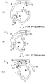
- FIG. 6 is a diagram showing an example in the case of variably controlling the moving speeds of the C-type arm 4 and the support arm 2 shown in FIG.
- the moving speed of the C-type arm 4 and the column-side arm 2 can be variably controlled.
- the C-type arm 4 and the column-side arm 2 are moved in the first movement speed mode in the first movement range until the C-type arm 4 and the column-side arm 2 reach predetermined positions
- the C-type arm 4 and the column-side arm in the second movement speed mode higher than the first movement speed mode.
- a control method for moving 2 is a control method for moving 2.
- the range in which vibration suppression is important can be set as the first movement range, and the range where the possibility of vibration is low can be set as the second movement range. If it does so, in the 1st movement range where suppression of vibration is important, it will become the 1st movement speed mode in which movement speed of C type arm 4 and supporter side arm 2 is comparatively slow. On the other hand, in the second movement range where the possibility of vibration is low, the second movement speed mode with a high movement speed is set.
- the C-arm 4 and the support arm 2 move at a low speed, so that vibration can be suppressed.
- the C-type arm 4 and the support arm 2 move at high speed, so that the exposure of the subject O can be reduced.
- the predetermined position as the switching position from the first movement speed mode to the second movement speed mode can be arbitrarily determined. For example, if the C-type arm 4 and the column-side arm 2 in the positional relationship shown in FIG. 6 (A) are moved to the position shown in FIG. 6 (C), the C-type as shown in FIG. 6 (B). When the arm main rotation shaft 5 is in the horizontal direction and the X-ray irradiation direction is in the vertical direction, the positions of the C-type arm 4 and the support arm 2 are switched from the first movement speed mode to the second movement speed mode. For a predetermined position.
- the positions of the C-type arm 4 and the column side arm 2 when the C-type main arm rotating shaft 5 is in the horizontal direction and the X-ray irradiation direction is in the vertical direction are set as default positions.
- the position can be a predetermined position for switching from the first movement speed mode to the second movement speed mode.
- the C-type arm 4 and the column-side arm 2 reach the predetermined position as the start position of the second movement range at the same timing, and the C-type arm 4 and the column-side arm 2 move at the same timing.
- the moving speeds of the C-arm 4 and the strut-side arm 2 in the first moving range are controlled.
- the data processing system 10 is a system that performs data processing on the data collected by the imaging system 6 under the control of the control system 8 as described above.
- the 2D image generation unit 13 can generate 2D-X-ray image data based on the X-ray detection data detected by the X-ray detector 12.
- the 2D image generation unit 13 can generate a plurality of frames of X-ray image data based on the X-ray detection data detected by the X-ray detector 12 while the C-arm 4 is rotating.
- the 3D image generation unit 14 can generate 3D-X-ray image data based on a plurality of frames of X-ray image data generated by the 2D image generation unit 13.
- the X-ray diagnostic apparatus 1 as described above is provided with two arms, a C-type arm 4 and a column-side arm 2 for positioning the imaging system 6, and the column-rotating shaft 3, the column-side arc slide shaft S1, C
- the imaging system 6 can be moved along the four axes of the mold arm main rotation shaft 5 and the C-arm slide axis S2.
- the X-ray diagnostic apparatus 1 can be used as a circulatory device.
- the C-arm main rotary shaft 5 can be tilted according to a site of interest such as a tilted blood vessel.
- the rotation of the support column turning shaft 3 and the slide operation of the support arm 2 in the direction of the support column arc slide axis S1 are parallel to the traveling direction of an arbitrary blood vessel traveling in a desired direction in the brain or heart.
- the arm main rotating shaft 5 can be set.
- shaft can be performed.
- the imaging system 6 can be moved within a wide range.
- the imaging system 6 can be moved within the camera. That is, the photographing system 6 can be moved beyond the sliding range of the C-arm 4 by the C-arm sliding mechanism 16.
- the imaging system 6 which is difficult in the past, such as sliding the C-arm 4 in the direction of the C-arm slide axis S2 with the X-ray generator 11 and the X-ray detector 12 arranged on the left and right of the subject O. Is possible. For this reason, the moving range of the imaging system 6 required for 3D imaging can be sufficiently covered.
- the support side arm 2 as the first arm 2 is attached to the ceiling via the support pivot shaft 3
- the first arm 2 is attached to the wall surface or floor surface of the photographing room. You may make it attach to. That is, the first arm 2 can be attached to the wall surface via the first rotating shaft 3. Alternatively, the first arm 2 can be placed on the floor surface via the first rotating shaft 3.
- the first arm 2 can be attached to the ceiling, wall surface or floor using the first rotating shaft 3 as a support.
- the second arm 4 that slides along the arcuate second slide axis S2 and holds the X-ray generator 11 and the X-ray detector 12 and the second arm 4 are slidably held.
- the X-ray diagnostic apparatus can be configured by the holding portion to be held and the first arm 2 that holds the holding portion in a slidable manner and is attached to at least one of the ceiling, floor, and wall.
- the number of arms, rotation shafts and slide shafts can be changed. Even in such a case, at least one slides along the arc-shaped slide axis by the slide guide mechanism 22 having a holding structure in which a plurality of spheres 21 roll on the arc-shaped rail 20 illustrated in FIG.
- An arm can be provided in the X-ray diagnostic apparatus. In this case, the arm that slides by the slide guide mechanism 22 or another arm can be rotated by the rotation shaft.
- the imaging system 6 including the X-ray generator 11 and the X-ray detector 12 can also be attached to an arm that slides by the slide guide mechanism 22 or another arm. Furthermore, a plurality of photographing systems 6 can be attached to the corresponding arms.
- the X-ray diagnostic apparatus 1 is a biplane type apparatus.
- the interference area by the first arm 2 and the second arm 4 is reduced. Can be made. That is, it is possible to avoid the occurrence of extremely protruding parts.
- control in the linked operation mode and the single operation mode can be specified even in an X-ray diagnostic apparatus having another structure.
- a plurality of arms are provided in the X-ray diagnostic apparatus.
- at least one of the plurality of arms is configured to be slidable along the arcuate slide axis.
- an arm that can slide along the slide axis or at least one other arm is configured to be rotatable about the rotation axis.
- the imaging system 6 including the X-ray generator 11 and the X-ray detector 12 is attached to a slidable arm or at least one other arm among the plurality of arms.
- the X-ray diagnostic apparatus is provided with a control system for imaging the subject O by controlling the plurality of arms and the imaging system 6.
- the control system starts the movement of the plurality of arms simultaneously at the time of starting the movement of the imaging system 6 and the first mode for starting and stopping the movement of the plurality of arms independently, while the imaging system 6 is stopped.
- the X-ray diagnostic apparatus is provided with an imaging function in the interlocking operation mode and the single operation mode by switching to the second mode in which the plurality of arms are simultaneously stopped in FIG. be able to.
Landscapes
- Health & Medical Sciences (AREA)
- Life Sciences & Earth Sciences (AREA)
- Engineering & Computer Science (AREA)
- Medical Informatics (AREA)
- Heart & Thoracic Surgery (AREA)
- Molecular Biology (AREA)
- Biophysics (AREA)
- High Energy & Nuclear Physics (AREA)
- Veterinary Medicine (AREA)
- Nuclear Medicine, Radiotherapy & Molecular Imaging (AREA)
- Optics & Photonics (AREA)
- Pathology (AREA)
- Radiology & Medical Imaging (AREA)
- Biomedical Technology (AREA)
- Public Health (AREA)
- Physics & Mathematics (AREA)
- Surgery (AREA)
- Animal Behavior & Ethology (AREA)
- General Health & Medical Sciences (AREA)
- Dentistry (AREA)
- Oral & Maxillofacial Surgery (AREA)
- Vascular Medicine (AREA)
- Neurology (AREA)
- Neurosurgery (AREA)
- General Engineering & Computer Science (AREA)
- Computer Vision & Pattern Recognition (AREA)
- Mechanical Engineering (AREA)
- Apparatus For Radiation Diagnosis (AREA)
Abstract
実施形態に係るX線診断装置は、第1の回転軸を中心に回転する第1のアーム、第2の回転軸を中心に回転する第2のアーム、保持部及び撮影系を備える。第1のアームは、円弧状の第1のスライド軸に沿って前記第1の回転軸に対して相対的にスライドする。第2のアームは、円弧状の第2のスライド軸に沿って前記第2の回転軸に対して相対的にスライドする。保持部は、前記第1のアーム側に連結され、前記第2のアームを保持する。撮影系は、前記第2のアームに取付けられたX線発生部及びX線検出器を含む。
Description
本発明の実施形態は、X線診断装置に関する。
X線診断装置では、例えば、X線発生部及びX線検出器が互いに対向した状態でC型アームによって保持される。特に、複数のアームを用いて一対のX線発生部及びX線検出器を駆動させるX線診断装置が提案されている。
例えば、第1の回転軸を中心に回転可能な支持基台に第1の円弧状のアーム及び第2の円弧状のアームを重ねてそれぞれスライド可能に配置し、X線発生部及びX線検出器を保持した第3の円弧状のアームのX線検出器側の端部を、第2の円弧状のアームに設けられた第2の回転軸に取付けた構造を有するX線診断装置が提案されている。
この構造を有するX線診断装置では、支持基台に固定された水平方向又は鉛直方向の第1の回転軸に加え、X線の照射方向と平行な第2の回転軸の2つの回転軸によってX線発生部及びX線検出器を位置決めすることができる。また、第1の円弧状のアーム及び第2の円弧状のアームの各スライド動作によってもX線発生部及びX線検出器の位置決めを行うことができる。
また、別の例として、第1の回転軸を中心に回転できるように天井に懸架され、かつ円弧状の軌道に沿ってスライドする第1の円弧状のアームの一端に第2の回転軸を設け、両端にX線発生部及びX線検出器を保持した第2の円弧状のアームの略中央部分を第2の回転軸に取付けた構造を有するX線診断装置が提案されている。この構造を有するX線診断装置では、天井に固定された第1の回転軸、第1の円弧状のアームのスライド動作及び第2の回転軸によってX線発生部及びX線検出器の位置決めを行うことができる。
X線診断装置では、3次元(3D: three dimensional)撮影や斜めに走行している血管の撮影など、様々な方向からの撮影を実行できるようにすることが望まれる。
そこで、本発明は、3D撮影や斜めに走行している血管の撮影など、多種多様な撮影を容易に実行することが可能なX線診断装置を提供することを目的とする。
本発明の実施形態に係るX線診断装置は、第1のアーム、第2のアーム、保持部及び撮影系を備える。第1のアームは、第1の回転軸を中心に回転し、かつ円弧状の第1のスライド軸に沿って前記第1の回転軸に対して相対的にスライドする。第2のアームは、第2の回転軸を中心に回転し、かつ円弧状の第2のスライド軸に沿って前記第2の回転軸に対して相対的にスライドする。保持部は、前記第1のアーム側に連結され、前記第2のアームを保持する。撮影系は、前記第2のアームに取付けられたX線発生部及びX線検出器を含む。
また、本発明の実施形態に係るX線診断装置は、アーム、回転軸及び撮影系を備える。アームは、円弧状のレール上を複数の球体が転動する保持構造を有するスライドガイド機構によって、少なくとも1つが円弧状のスライド軸に沿ってスライドする。回転軸は、前記又は他のアームを回転させる。撮影系は、前記又は他のアームに取付けられたX線発生部及びX線検出器を含む。
また、本発明の実施形態に係るX線診断装置は、複数のアーム、撮影系及び制御系を備える。複数のアームは、少なくとも1つが円弧状のスライド軸に沿ってスライドし、かつ前記又は他の少なくとも1つが回転軸を中心に回転する。撮影系は、前記複数のアームの前記又は他の少なくとも1つに取付けられたX線発生部及びX線検出器を含む。制御系は、前記複数のアーム及び前記撮影系を制御することによって被検体の撮影を行う。また、前記制御系は、前記複数のアームをそれぞれ独立して移動開始及び停止させる第1のモードと、前記撮影系の移動開始時において前記複数のアームの移動を同時に開始させる一方、前記撮影系の停止時において前記複数のアームを同時に停止させる第2のモードとを切換えて前記複数のアーム及び前記撮影系を制御できるように構成される。
また、本発明の実施形態に係るX線診断装置は、第1のアーム、保持部及び第2のアームを備える。第1のアームは、円弧状のスライド軸に沿ってスライドし、X線発生部及びX線検出器を保持する。保持部は、前記第1のアームをスライド可能に保持する。第2のアームは、前記保持部をスライド可能に保持し、天井、床及び壁の少なくとも1つに取付けられる。
また、本発明の実施形態に係るX線診断装置は、アーム、回転軸及び撮影系を備える。アームは、円弧状のレール上を複数の球体が転動する保持構造を有するスライドガイド機構によって、少なくとも1つが円弧状のスライド軸に沿ってスライドする。回転軸は、前記又は他のアームを回転させる。撮影系は、前記又は他のアームに取付けられたX線発生部及びX線検出器を含む。
また、本発明の実施形態に係るX線診断装置は、複数のアーム、撮影系及び制御系を備える。複数のアームは、少なくとも1つが円弧状のスライド軸に沿ってスライドし、かつ前記又は他の少なくとも1つが回転軸を中心に回転する。撮影系は、前記複数のアームの前記又は他の少なくとも1つに取付けられたX線発生部及びX線検出器を含む。制御系は、前記複数のアーム及び前記撮影系を制御することによって被検体の撮影を行う。また、前記制御系は、前記複数のアームをそれぞれ独立して移動開始及び停止させる第1のモードと、前記撮影系の移動開始時において前記複数のアームの移動を同時に開始させる一方、前記撮影系の停止時において前記複数のアームを同時に停止させる第2のモードとを切換えて前記複数のアーム及び前記撮影系を制御できるように構成される。
また、本発明の実施形態に係るX線診断装置は、第1のアーム、保持部及び第2のアームを備える。第1のアームは、円弧状のスライド軸に沿ってスライドし、X線発生部及びX線検出器を保持する。保持部は、前記第1のアームをスライド可能に保持する。第2のアームは、前記保持部をスライド可能に保持し、天井、床及び壁の少なくとも1つに取付けられる。
本発明の実施形態に係るX線診断装置について添付図面を参照して説明する。
図1は本発明の実施形態に係るX線診断装置の構成図である。
X線診断装置1は、第1のアーム2、第1の回転軸3、第2のアーム4、第2の回転軸5、撮影系6、寝台7、制御系8、コンソール9及びデータ処理系10を備えている。撮影系6は、X線発生部11及びX線検出器12を含む。また、データ処理系10は、2次元(2D: two dimensional)画像生成部13及び3D画像生成部14を有する。
第1のアーム2は、第1の回転軸3を中心に回転させることができる。また、第1のアーム2は、図示されるように第1の回転軸3を支柱として天井に取付けることができる。従って、以降では、第1のアーム2を支柱側アーム2と称し、第1の回転軸3を支柱旋回軸3と称する。
支柱側アーム2は、第1のスライド機構15により、円弧状の第1のスライド軸S1に沿って支柱旋回軸3に対して相対的にスライドすることができるように構成される。従って、支柱側アーム2の形状も円弧状とすることができる。以降では、第1のスライド軸S1を支柱側円弧スライド軸S1と称し、第1のスライド機構15を支柱側アームスライド機構15と称する。
一方、第2のアーム4は、第2の回転軸5を中心に回転させることができる。第2のアーム4には、撮影系6が取付けられる。典型的には、図示されるように、第2のアーム4の一端にX線を被検体Oに向けて照射するためのX線管を備えたX線発生部11が固定され、第2のアーム4の他端に、寝台7にセットされた被検体Oを挟んでX線発生部11に対向するようにX線検出器12が固定される。従って、第2のアーム4の形状は、C型となる。従って、以降では、第2のアーム4をC型アーム4と称し、第2の回転軸5をC型アーム主回転軸5と称する。
C型アーム4は、第2のスライド機構16により、円弧状の第2のスライド軸S2に沿ってC型アーム主回転軸5に対して相対的にスライドすることができるように構成される。このため、第2のスライド機構16は、支柱側アーム2側に連結され、C型アーム4をスライド可能に保持する保持部としての機能を兼ねている。但し、第2のスライド機構16とは別の構成要素として、支柱側アーム2側に連結され、C型アーム4を保持する保持部を設けてもよい。
以降では、第2のスライド軸S2をC型アームスライド軸S2と称し、第2のスライド機構16をC型アームスライド機構16と称する。C型アームスライド軸S2方向におけるC型アーム4の駆動によって、C型アーム4の所望の位置を回転軸としてC型アーム主回転軸5によりC型アーム4をプロペラのように回転させることができる。つまり、C型アーム主回転軸5は、中心線としての第2の回転軸5を中心としてC型アーム4を回転させる回転機構として機能する。
C型アーム4を回転させるための回転機構としてのC型アーム主回転軸5は、支柱側アーム2に固定される。従って、C型アーム主回転軸5自体を、C型アーム4と共に支柱側円弧スライド軸S1に沿って移動させることができる。加えて、C型アーム4及びC型アーム主回転軸5を、支柱側アーム2と共に支柱旋回軸3を中心に回転させることができる。このため、C型アーム4及びC型アーム主回転軸5を、任意の角度に傾斜させることが可能である。尚、C型アーム主回転軸5の支柱側アーム2への取付位置は、支柱側アーム2の端部が周辺器材の障害物となって干渉の原因となることを防止する観点から、支柱側アーム2の端部とすることが望ましい。
図2は、図1に示すC型アーム主回転軸5を被検体Oの撮影断面に合わせて傾斜させた例を示す図である。
支柱側アームスライド機構15及び支柱旋回軸3を動作させると、図2に示すように、C型アーム主回転軸5を任意の角度に傾斜させることができる。このため、脳や心臓等の撮影部位内において水平方向に対して斜めに走行している血管Bが治療対象であっても、斜めに走行する血管Bの走行方向と平行になるようにC型アーム主回転軸5を位置決めすることが可能となる。
そして、斜行する血管Bの断面に垂直となる方向にC型アーム主回転軸5をセットした状態で、アイソセンタ(治療中心)軸を中心としてC型アーム4をプロペラのように回転させることができる。すなわち、C型アーム主回転軸5の回転動作によって、被検体Oの体軸に対して傾斜するアイソセンタ軸を中心として、軌跡が円形となるようにX線発生部11及びX線検出器12を含む撮影系6を回転させることができる。これにより、斜めに走行する血管B等の傾斜する関心部位における形態を容易に観察することが可能なX線画像を撮影することができる。
図3は、図1に示すC型アーム主回転軸5を被検体Oの体軸に合わせて傾斜させた例を示す図である。
C型アーム主回転軸5は、被検体Oの撮影断面に限らず、被検体Oの体軸に合わせて傾斜させることもできる。例えば、炭酸ガスを造影剤として用いる場合には、炭酸ガスの比重が空気よりも重いことから撮影部位が低位置となるように寝台7を傾けることが望ましい。その場合には、被検体Oの体軸が寝台7と共に傾斜することになる。
そこで、図3に示すようにC型アーム主回転軸5を被検体Oの体軸に合わせて傾斜させることができる。逆に、造影剤である炭酸ガスが被検体Oの撮影部位に十分に供給されるように、被検体Oをセットするための寝台7をC型アーム主回転軸5の傾斜方向に応じて傾斜させることができる。
つまり、寝台7をチルトさせ、かつ寝台7の高さが低い側に被検体Oの撮影部位が存在する場合であっても、寝台7の傾斜角度に合わせてC型アーム主回転軸5を傾斜させることができる。そして、撮影系6と共にC型アーム4をプロペラのように回転させて3D撮影を行うことが可能である。
図2及び図3に例示されるように、支柱側アーム2が移動することによって傾斜したC型アーム主回転軸5を中心としてC型アーム4を回転させることができる。
また、支柱旋回軸3及びC型アーム主回転軸5の回転動作によって、支柱側円弧スライド軸S1とC型アームスライド軸S2とが同一平面上となるようにすれば、支柱側円弧スライド軸S1とC型アームスライド軸S2とが同心円状となる。このため、C型アーム4の同一平面内における旋回可能な角度の範囲を、C型アームスライド機構16の可動範囲に支柱側アームスライド機構15の可動範囲を加えた範囲とすることができる。その結果、3D撮影用に180度以上の角度範囲に亘って撮影系6を傾斜させることが可能となる。
支柱側アーム2を支柱側円弧スライド軸S1に沿ってスライドさせるための支柱側アームスライド機構15及びC型アーム4をC型アームスライド軸S2に沿ってスライドさせるためのC型アームスライド機構16には、任意の構造を採用することができる。典型的には、円弧状に湾曲するレール上を円筒状の車輪が走行するスライドガイド機構を支柱側アームスライド機構15及びC型アームスライド機構16の一方又は双方に用いることができる。
但し、支柱側アームスライド機構15には、撮影系6、C型アーム4、C型アーム主回転軸5及び支柱側アーム2の荷重がかかることになる。従って、支柱側アームスライド機構15は、剛性が高い構造とすることが振動の抑制による画質の向上に繋がる。
図4は、図1に示す支柱側アームスライド機構15及びC型アームスライド機構16として採用可能なスライド機構の例を示す斜視図である。
図4に示すように、円弧状のレール20上を複数の球体21が転動する保持構造を有するスライドガイド機構22を支柱側アームスライド機構15及びC型アームスライド機構16の一方又は双方に用いることができる。少なくとも支柱側アーム2を図4に示すような複数の球体21が転動する保持構造を有するスライドガイド機構22で支柱側円弧スライド軸S1に沿ってスライドさせるようにすれば、支柱側アーム2に負荷される荷重に対して良好に対抗することができる。つまり、複数の球体21が転動する保持構造を有するスライドガイド機構22を、少なくとも支柱側アームスライド機構15として採用すれば、十分な剛性を確保することができる。
特に、図4に例示されるように、スライドガイド機構22の構造を、レール20の四隅に設けられた受け面上をそれぞれ複数の球体21が転動する保持構造とすれば、レール20に四方から等荷重がかかるようにすることができる。
また、図4に例示されたスライドガイド機構22は、循環する複数の球体21の一部がレール20上を転動する保持構造を有している。すなわち、レール20に沿ってスライドする保持ブロック23に複数の球体21を循環させるための経路として貫通孔が設けられている。また、レール20の受け面と保持ブロック23との間における空隙として形成される球体21の経路に、保持ブロック23の貫通孔から転動してくる球体21を案内するために、保持ブロック23の両サイドにエンドプレート24が設けられている。このようなスライドガイド機構22の構造により、保持ブロック23の滑らかなスライド及び摩耗の抑制が可能となる。
C型アームスライド機構16についても図4に示すようなスライドガイド機構22を採用すれば、円筒状の車輪を走行させる構造を有する従来のスライド機構を採用する場合に比べて、サイズを小さくすることができる。このため、干渉の低減に寄与することができる。逆に、荷重が比較的小さいC型アームスライド機構16については、円筒状の車輪を走行させる構造を有する従来のスライド機構を採用するようにしてもよい。その場合には、C型アームスライド機構16の構造の簡易化及びコストの低減が可能である。
また、支柱側アームスライド機構15のスライド動作範囲の決定によって、支柱側アームスライド機構15の駆動に要する回転トルクの低減を図ることができる。具体的には、支柱側アーム2の支柱側円弧スライド軸S1に沿うスライド範囲を、C型アーム4のC型アームスライド軸S2に沿うスライド範囲よりも短くすることによって、支柱側アームスライド機構15の動作に必要な移動速度をC型アームスライド機構16の移動速度よりも、スライド動作範囲の比に合わせて遅くすることができる。このため、支柱側アームスライド機構15の駆動に要する回転トルクの低減を図ることができる。
図5は、図1に示す支柱側アームスライド機構15及びC型アームスライド軸S2の双方のスライド動作によってC型アーム4を回転させた例を示す図である。
図5に示すように、支柱側アームスライド機構15及びC型アームスライド機構16の双方のスライド動作によって、C型アーム4のC型アームスライド軸S2方向における回転範囲をC型アームスライド機構16の可動範囲よりも長くすることができる。
但し、支柱側アームスライド機構15には、上述のように撮影系6、C型アーム4、C型アーム主回転軸5及び支柱側アーム2の荷重がかかる。従って、支柱側アーム2をスライドさせるための回転トルクは、C型アーム4をスライドさせるための回転トルクよりも大きくなる。
そこで、図5に示すように、例えば、支柱側アームスライド機構15による支柱側アーム2のスライド動作範囲R1を40度とする一方、C型アームスライド機構16によるC型アーム4のスライド動作範囲R2を160度とすることができる。つまり、支柱側アーム2の支柱側円弧スライド軸S1方向における回転可能な角度範囲を、C型アーム4のC型アームスライド軸S2方向における回転可能な角度範囲の1/4程度に設定することができる。
そうすると、支柱側アームスライド機構15の移動速度は、概ねC型アームスライド機構16の移動速度の1/4程度となる。これにより、C型アームスライド機構16によってC型アーム4をスライドさせるための駆動電源と同等な駆動電源を用いて、C型アーム4よりも回転トルクが大きい支柱側アーム2をスライドさせることが可能となる。
つまり、支柱側アームスライド機構15による支柱側アーム2のスライド動作範囲を限定することによって、汎用的かつ現実的な駆動電源及び駆動機構を用いて支柱側アームスライド機構15を駆動させることが可能となる。尚、C型アームスライド機構16及び支柱側アームスライド機構15を駆動させるための汎用的な駆動機構の例としては、サーボモータとウォーム減速機で構成される駆動機構が挙げられる。また、車輪の走行によるスライドガイド機構であるか図4に示すような球体21の循環転動によるスライドガイド機構であるかに依らず、スライド駆動機構には、公知の任意の駆動機構を用いることができる。
制御系8は、支柱側アーム2、C型アーム4及び撮影系6を制御することによって被検体Oの撮影を行うためのシステムである。すなわち、制御系8からの制御信号によって、支柱旋回軸3及び支柱側アームスライド機構15が制御される。これにより、支柱側アーム2の位置決めを行うことができる。同様に、制御系8からの制御信号によって、C型アーム主回転軸5及びC型アームスライド機構16が制御される。これにより、C型アーム4の位置決めを行うことができる。更に、制御系8に備えられる高電圧発生装置から電圧をX線発生部11に印加することによって、被検体Oに向けてX線を曝射することができる。その他、制御系8には、寝台7を駆動させるための駆動装置を始めとする撮影に必要な装置が備えられる。また、制御系8に入力すべき指示情報は、コンソール9から入力することができる。
特に、制御系8は、第1のモードと第2のモードとを切換えて支柱側アーム2、C型アーム4及び撮影系6を制御できるように構成される。第1のモードは、支柱側アーム2及びC型アーム4をそれぞれ独立したスライド動作によって移動開始及び停止させる単独動作モードである。一方、第2のモードは、支柱側アーム2及びC型アーム4を連動して移動させる連動動作モードである。
連動動作モードでは、例えば、支柱側アーム2及びC型アーム4の移動速度をそれぞれ制御することにより、撮影系6の移動開始時において支柱側アーム2及びC型アーム4のスライド動作による移動を同時に開始させ、撮影系6の停止時において支柱側アーム2及びC型アーム4を同時に停止させることができる。動作モードの選択は、コンソール9から指示情報を制御系8に入力することによって行うことができる。
支柱側アーム2及びC型アーム4をそれぞれ独立して動作させる単独動作モードは、主として、図2に示すような傾斜した撮影部位の撮影のために選択することができる。一方、支柱側アーム2及びC型アーム4を連動させて動作させる連動動作モードは、主として3D撮影のように被検体Oに向けて180度以上の角度範囲における複数の方向からX線を曝射して撮影を行う場合に選択することができる。つまり、撮影系6のスライド動作による移動領域が広範囲である場合に連動動作モードを選択することができる。
C型アーム主回転軸5を含む平面内において撮影系6を180度以上回転させる場合には、上述のようにC型アーム4と支柱側アーム2の双方がC型アーム主回転軸5を含む平面内においてスライドすることとなる。また、支柱旋回軸3及びC型アーム主回転軸5の一方又は双方を動作させながら、C型アーム4と支柱側アーム2の双方をスライドさせることも可能である。
このように、C型アームスライド機構16と支柱側アームスライド機構15の双方を動作させる場合には、C型アーム4及び支柱側アーム2の一方の駆動中に他方が停止したり、逆にC型アーム4及び支柱側アーム2の一方が先に駆動を開始しないように、C型アーム4及び支柱側アーム2の移動速度を制御することができる。
この場合、C型アーム4及び支柱側アーム2がスライド動作によりスタート位置から移動を開始するタイミングが互いに一致し、かつ停止位置に到達するタイミングが互いに一致するように、C型アーム4のスライド範囲と支柱側アーム2のスライド範囲に合わせてC型アーム4及び支柱側アーム2の移動速度が制御される。従って、C型アーム4のスライド距離が支柱側アーム2のスライド距離と異なれば、C型アーム4の移動速度は支柱側アーム2の移動速度と異なる速度となる。
具体例として、C型アーム4のスライド範囲が160°であり、支柱側アーム2のスライド範囲が40°である場合には、支柱側アーム2の移動速度をC型アーム4の移動速度の1/4とすればよい。例えば、C型アーム4の角速度が40度/秒であれば、支柱側アーム2の角速度を10度/秒に設定すればよい。
このような速度制御によりC型アーム4及び支柱側アーム2の全てのスライド動作範囲において不連続な動作を回避することができる。すなわち、C型アーム4及び支柱側アーム2を、移動開始から停止まで互いに連続動作させることができる。これにより、C型アーム4及び支柱側アーム2の一方が他方と異なるタイミングで移動開始又は停止する場合に生じる慣性負荷による振動を回避することができる。その結果、振動とともに振動に起因する3D画像の画質劣化を低減させることができる。
図6は、図1に示すC型アーム4及び支柱側アーム2の移動速度を可変制御する場合の例を示す図である。
C型アーム4及び支柱側アーム2の連動動作モードにおいてC型アーム4及び支柱側アーム2の移動速度を可変制御することもできる。制御が容易な例として、C型アーム4及び支柱側アーム2が所定の位置となるまでの第1の移動範囲では第1の移動速度モードでC型アーム4及び支柱側アーム2を移動させる一方、C型アーム4及び支柱側アーム2が所定の位置となった後の第2の移動範囲では第1の移動速度モードよりも高速の第2の移動速度モードでC型アーム4及び支柱側アーム2を移動させる制御方法が挙げられる。
この場合、振動の抑制が重要な範囲を第1の移動範囲とし、振動の可能性が低い範囲を第2の移動範囲とすることができる。そうすると、振動の抑制が重要な第1の移動範囲では、C型アーム4及び支柱側アーム2の移動速度が比較的遅い第1の移動速度モードとなる。逆に、振動の可能性が低い第2の移動範囲では移動速度が速い第2の移動速度モードとなる。
この結果、振動の抑制が重要な第1の移動範囲ではC型アーム4及び支柱側アーム2が低速で移動するため、振動を抑制することができる。一方、振動の可能性が低い第2の移動範囲ではC型アーム4及び支柱側アーム2が高速で移動するため、被検体Oの被爆を低減することができる。
第1の移動速度モードから第2の移動速度モードへの切換位置となる所定の位置は、任意に決定することができる。例えば、図6(A)に示す位置関係にあるC型アーム4及び支柱側アーム2を図6(C)に示す位置に移動させる場合であれば、図6(B)に示すようにC型アーム主回転軸5が水平方向となり、かつX線の照射方向が鉛直方向となる時のC型アーム4及び支柱側アーム2の位置を第1の移動速度モードから第2の移動速度モードへ切換えるための所定の位置とすることができる。
すなわち、図1に示すようにC型アーム主回転軸5が水平方向となり、かつX線の照射方向が鉛直方向となる時のC型アーム4及び支柱側アーム2の位置をデフォルト位置とし、デフォルト位置を第1の移動速度モードから第2の移動速度モードへ切換えるための所定の位置とすることができる。
この場合、図6(A)に示すように、C型アーム4及び支柱側アーム2の自重によって支柱側アームスライド機構15及び支柱旋回軸3に回転モーメントが負荷され、振動が発生する恐れがある第1の移動範囲ではC型アーム4及び支柱側アーム2が低速モードで移動する。これにより、C型アーム4及び支柱側アーム2の移動による振動が抑制される。
一方、図6(B)に示すC型アーム4及び支柱側アーム2の標準位置から図6(C)に示すような支柱側アームスライド機構15及び支柱旋回軸3に負荷される回転モーメントが小さくなる位置までの第2の移動範囲ではC型アーム4及び支柱側アーム2が高速モードで移動する。これにより、X線の照射時間を短くし、被検体Oの被爆を低減することができる。
別の例として、第2の移動範囲においてC型アーム4及び支柱側アーム2を最大速度で移動させた場合に停止タイミングが一致するように第1の移動速度モードから第2の移動速度モードへの切換位置となる所定の位置、つまり第2の移動範囲の開始位置を決定してもよい。この場合、第2の移動範囲の開始位置となる所定の位置に同一のタイミングでC型アーム4及び支柱側アーム2が到達し、かつC型アーム4及び支柱側アーム2が同一のタイミングで移動を開始するように第1の移動範囲におけるC型アーム4及び支柱側アーム2の移動速度が制御されることになる。
一方、データ処理系10は、上述したような制御系8による制御下における撮影系6によって収集されたデータに対してデータ処理を行うシステムである。2D画像生成部13では、X線検出器12により検出されたX線検出データに基づいて2D-X線画像データを生成することができる。
特に、支柱側アーム2をスライドさせることによってC型アーム主回転軸5が傾斜した状態でC型アーム4をプロペラのように回転させた場合には、傾斜したC型アーム主回転軸5を中心とするC型アーム4の回転中にX線検出器12によりX線検出データが検出される。このため、2D画像生成部13では、C型アーム4の回転中にX線検出器12により検出されたX線検出データに基づいて複数フレームのX線画像データを生成することができる。
更に、3D画像生成部14では、2D画像生成部13において生成された複数フレームのX線画像データに基づいて3D-X線画像データを生成することができる。
つまり以上のようなX線診断装置1は、撮影系6の位置決めのためにC型アーム4及び支柱側アーム2の2つのアームを設け、かつ支柱旋回軸3、支柱側円弧スライド軸S1、C型アーム主回転軸5及びC型アームスライド軸S2の4つの軸に沿って撮影系6を移動できるようにしたものである。
このため、X線診断装置1を循環器用の装置として用いることができる。特に、X線診断装置1によれば、傾斜する血管等の関心部位に合わせてC型アーム主回転軸5を傾斜させることができる。例えば、支柱旋回軸3の回転及び支柱側円弧スライド軸S1方向における支柱側アーム2のスライド動作によって、脳や心臓において所望の方向に走行する任意の血管の走行方向と平行となるようにC型アーム主回転軸5をセットすることが可能となる。そして、被検体Oの体軸を中心とする回転撮影に限らず、傾斜するアイソセンタ軸を中心とする回転撮影を行うことができる。典型的には、傾斜する血管の断面に垂直な方向を中心とする回転撮影を行うことが可能となる。これにより、血管の形状を把握するために好適なX線画像を撮影することができる。
加えて、X線診断装置1によれば、撮影系6を広い範囲内で移動させることができる。特に、支柱側円弧スライド軸S1方向への支柱側アーム2のスライドと、C型アームスライド軸S2方向へのC型アーム4のスライドを併用することによって、3D撮影に十分に対応し得る広い範囲内で撮影系6を移動させることができる。すなわち、C型アームスライド機構16によるC型アーム4のスライド範囲を超えた撮影系6の移動が可能である。また、X線発生部11とX線検出器12を被検体Oの左右に配置した状態でC型アーム4をC型アームスライド軸S2方向にスライドさせるといった従来では困難な撮影系6の移動が可能である。このため、3D撮影に必要とされる撮影系6の移動範囲を十分にカバーすることができる。
以上、特定の実施形態について記載したが、記載された実施形態は一例に過ぎず、発明の範囲を限定するものではない。ここに記載された新規な方法及び装置は、様々な他の様式で具現化することができる。また、ここに記載された方法及び装置の様式において、発明の要旨から逸脱しない範囲で、種々の省略、置換及び変更を行うことができる。添付された請求の範囲及びその均等物は、発明の範囲及び要旨に包含されているものとして、そのような種々の様式及び変形例を含んでいる。
例えば、上述した実施形態では、第1のアーム2としての支柱側アーム2を支柱旋回軸3を介して天井に取付けた例を示したが、第1のアーム2を撮影室の壁面や床面に取付けるようにしてもよい。すなわち、第1のアーム2を第1の回転軸3を介して壁面に取付けることができる。或いは、第1のアーム2を第1の回転軸3を介して床面に据え置くこともできる。
つまり、第1のアーム2は、第1の回転軸3を支柱として天井、壁面又は床に取付けることができる。換言すれば、円弧状の第2のスライド軸S2に沿ってスライドし、X線発生部11及びX線検出器12を保持する第2のアーム4と、第2のアーム4をスライド可能に保持する保持部と、保持部をスライド可能に保持し、天井、床及び壁の少なくとも1つに取付けられた第1のアーム2とによってX線診断装置を構成することができる。
また、アーム、回転軸及びスライド軸の数をそれぞれ変えることもできる。その場合においても、図4に例示されるような円弧状のレール20上を複数の球体21が転動する保持構造を有するスライドガイド機構22によって少なくとも1つが円弧状のスライド軸に沿ってスライドするアームをX線診断装置に設けることができる。この場合、回転軸により、スライドガイド機構22によってスライドするアーム又は他のアームを回転させるようにすることができる。また、X線発生部11及びX線検出器12を含む撮影系6についても、スライドガイド機構22によってスライドするアーム又は他のアームに取付けることができる。更に、複数の撮影系6を対応するアームに取付けることもできる。この場合、X線診断装置1は、バイプレーンタイプの装置となる。
但し、上述した実施形態のように、第1のアーム2及び第2のアーム4をそれぞれスライド移動させることができるようにすれば、第1のアーム2及び第2のアーム4による干渉領域を低減させることができる。すなわち、極端に突出する部位が生じることを回避することができる。
また、連動動作モードと単独動作モードによる制御は、他の構造を有するX線診断装置においても指定できるようにすることができる。その場合には、複数のアームがX線診断装置に備えられる。そして、複数のアームの少なくとも1つが円弧状のスライド軸に沿ってスライドできるように構成される。更に、スライド軸に沿ってスライド可能なアーム又は他の少なくとも1つのアームが回転軸を中心に回転できるように構成される。そして、X線発生部11及びX線検出器12を含む撮影系6は、複数のアームのうちのスライド可能なアーム又は他の少なくとも1つのアームに取付けられる。また、X線診断装置には、複数のアーム及び撮影系6を制御することによって被検体Oの撮影を行う制御系が備えられる。
そして、制御系を、複数のアームをそれぞれ独立して移動開始及び停止させる第1のモードと、撮影系6の移動開始時において複数のアームの移動を同時に開始させる一方、撮影系6の停止時において複数のアームを同時に停止させる第2のモードとを切換えて複数のアーム及び撮影系6を制御できるように構成することによって、連動動作モード及び単独動作モードによる撮影機能をX線診断装置に設けることができる。
Claims (15)
- 第1の回転軸を中心に回転し、かつ円弧状の第1のスライド軸に沿って前記第1の回転軸に対して相対的にスライドする第1のアームと、
第2の回転軸を中心に回転し、かつ円弧状の第2のスライド軸に沿って前記第2の回転軸に対して相対的にスライドする第2のアームと、
前記第1のアーム側に連結され、前記第2のアームを保持する保持部と、
前記第2のアームに取付けられたX線発生部及びX線検出器を含む撮影系と、
を備えるX線診断装置。 - 少なくとも前記第1のアームは、円弧状のレール上を複数の球体が転動する保持構造を有するスライドガイド機構によって、前記第1のスライド軸に沿ってスライドするように構成される請求項1記載のX線診断装置。
- 前記第1のアーム及び前記第2のアームをそれぞれ独立して移動開始及び停止させる第1のモードと、前記第1のアーム及び前記第2のアームを連動して移動させる第2のモードとを切換えて前記第1のアーム、前記第2のアーム及び前記撮影系を制御することによって被検体の撮影を行う制御系を更に備える請求項1記載のX線診断装置。
- 前記第1のアームが移動することによって傾斜した前記第2の回転軸を中心として前記第2のアームを回転させる回転機構を更に有する請求項1記載のX線診断装置。
- 被検体をセットし、前記第2の回転軸の傾斜方向に応じて傾斜する寝台を更に有する請求項1記載のX線診断装置。
- 前記傾斜した前記第2の回転軸を中心とする前記第2のアームの回転中に前記X線検出器により検出されたX線検出データに基づいて複数フレームのX線画像データを生成する2次元画像生成部と、
前記複数フレームのX線画像データに基づいて3次元画像データを生成する3次元画像生成部と、
を更に有する請求項4記載のX線診断装置。 - 前記第1のアーム及び前記第2のアームの移動速度をそれぞれ制御することにより、前記撮影系の移動開始時において前記第1のアーム及び前記第2のアームの移動を同時に開始させる一方、前記撮影系の停止時において前記第1のアーム及び前記第2のアームを同時に停止させる制御系を更に備える請求項1記載のX線診断装置。
- 前記制御系は、前記第1のアーム及び前記第2のアームが所定の位置となるまでの第1の移動範囲では第1の移動速度モードで前記第1のアーム及び前記第2のアームを移動させる一方、前記第1のアーム及び前記第2のアームが前記所定の位置となった後の第2の移動範囲では前記第1の移動速度モードよりも高速の第2の移動速度モードで前記第1のアーム及び前記第2のアームを移動させるように構成される請求項7記載のX線診断装置。
- 前記第1のアームを、前記第1の回転軸を支柱として天井、壁面又は床に取付けた請求項1記載のX線診断装置。
- 前記第1のアームの前記第1のスライド軸に沿うスライド範囲を、前記第2のアームの前記第2のスライド軸に沿うスライド範囲よりも短くした請求項1記載のX線診断装置。
- 円弧状のレール上を複数の球体が転動する保持構造を有するスライドガイド機構によって、少なくとも1つが円弧状のスライド軸に沿ってスライドするアームと、
前記又は他のアームを回転させる回転軸と、
前記又は他のアームに取付けられたX線発生部及びX線検出器を含む撮影系と、
を備えるX線診断装置。 - 前記スライドガイド機構は、前記レールの四隅に設けられた受け面上をそれぞれ前記複数の球体が転動する保持構造を有する請求項11記載のX線診断装置。
- 前記スライドガイド機構は、循環する複数の球体の一部が前記レール上を転動する保持構造を有する請求項11記載のX線診断装置。
- 少なくとも1つが円弧状のスライド軸に沿ってスライドし、かつ前記又は他の少なくとも1つが回転軸を中心に回転する複数のアームと、
前記複数のアームの前記又は他の少なくとも1つに取付けられたX線発生部及びX線検出器を含む撮影系と、
前記複数のアーム及び前記撮影系を制御することによって被検体の撮影を行う制御系とを備え、
前記制御系は、前記複数のアームをそれぞれ独立して移動開始及び停止させる第1のモードと、前記撮影系の移動開始時において前記複数のアームの移動を同時に開始させる一方、前記撮影系の停止時において前記複数のアームを同時に停止させる第2のモードとを切換えて前記複数のアーム及び前記撮影系を制御できるように構成されるX線診断装置。 - 円弧状のスライド軸に沿ってスライドし、X線発生部及びX線検出器を保持する第1のアームと、
前記第1のアームをスライド可能に保持する保持部と、
前記保持部をスライド可能に保持し、天井、床及び壁の少なくとも1つに取付けられた第2のアームと、
を備えるX線診断装置。
Priority Applications (3)
| Application Number | Priority Date | Filing Date | Title |
|---|---|---|---|
| CN201480014801.1A CN105188538B (zh) | 2013-03-14 | 2014-03-13 | X射线诊断装置 |
| US14/845,366 US9737275B2 (en) | 2013-03-14 | 2015-09-04 | X-ray diagnostic apparatus |
| US15/638,969 US10080537B2 (en) | 2013-03-14 | 2017-06-30 | X-ray diagnostic apparatus |
Applications Claiming Priority (2)
| Application Number | Priority Date | Filing Date | Title |
|---|---|---|---|
| JP2013052181 | 2013-03-14 | ||
| JP2013-052181 | 2013-03-14 |
Related Child Applications (1)
| Application Number | Title | Priority Date | Filing Date |
|---|---|---|---|
| US14/845,366 Continuation US9737275B2 (en) | 2013-03-14 | 2015-09-04 | X-ray diagnostic apparatus |
Publications (1)
| Publication Number | Publication Date |
|---|---|
| WO2014142244A1 true WO2014142244A1 (ja) | 2014-09-18 |
Family
ID=51536893
Family Applications (1)
| Application Number | Title | Priority Date | Filing Date |
|---|---|---|---|
| PCT/JP2014/056692 Ceased WO2014142244A1 (ja) | 2013-03-14 | 2014-03-13 | X線診断装置 |
Country Status (4)
| Country | Link |
|---|---|
| US (2) | US9737275B2 (ja) |
| JP (1) | JP6274518B2 (ja) |
| CN (1) | CN105188538B (ja) |
| WO (1) | WO2014142244A1 (ja) |
Families Citing this family (17)
| Publication number | Priority date | Publication date | Assignee | Title |
|---|---|---|---|---|
| JP6448969B2 (ja) * | 2013-12-10 | 2019-01-09 | キヤノンメディカルシステムズ株式会社 | X線診断装置 |
| WO2016064993A1 (en) * | 2014-10-22 | 2016-04-28 | Carestream Health, Inc. | Mobile radiographic imaging apparatus |
| DE102015202082A1 (de) * | 2015-02-05 | 2015-12-17 | Siemens Aktiengesellschaft | Deckengebundenes medizinisches Röntgengerät |
| BR112018000628A2 (pt) | 2015-07-16 | 2018-09-18 | Koninklijke Philips Nv | dispositivo para imageamento por raios x, e sistema para imageamento de raios x |
| US10842453B2 (en) * | 2016-02-03 | 2020-11-24 | Globus Medical, Inc. | Portable medical imaging system |
| CN206228357U (zh) * | 2016-06-03 | 2017-06-09 | 北京东软医疗设备有限公司 | 一种悬吊机架 |
| CN107518907A (zh) | 2016-06-22 | 2017-12-29 | 沈阳东软医疗系统有限公司 | 一种医疗影像装置及其机架 |
| CN110121299A (zh) * | 2016-11-04 | 2019-08-13 | 霍罗吉克公司 | 医学成像装置和操作医学成像装置的方法 |
| US10470728B2 (en) * | 2017-03-21 | 2019-11-12 | General Electric Company | Orbital rotation positioning device for a C-arm of an imaging system |
| US11311257B2 (en) * | 2018-08-14 | 2022-04-26 | General Electric Company | Systems and methods for a mobile x-ray imaging system |
| US10517554B1 (en) * | 2018-09-07 | 2019-12-31 | Shimadzu Corporation | X-ray fluoroscopic imaging apparatus |
| JP7532402B2 (ja) * | 2019-04-01 | 2024-08-13 | キャスワークス リミテッド | 血管造影画像選択のための方法および装置 |
| JP2021074261A (ja) * | 2019-11-08 | 2021-05-20 | 株式会社島津製作所 | 放射線撮影装置 |
| JP7794612B2 (ja) * | 2021-11-25 | 2026-01-06 | キヤノンメディカルシステムズ株式会社 | X線診断装置及びx線診断装置の制御方法 |
| JP7827499B2 (ja) * | 2022-03-15 | 2026-03-10 | キヤノンメディカルシステムズ株式会社 | X線診断装置 |
| IL326432A (en) | 2023-08-09 | 2026-04-01 | Cathworks Ltd | Coronary artery assessment after PCI |
| US12512196B2 (en) | 2024-06-12 | 2025-12-30 | Cathworks Ltd. | Systems and methods for secure sharing of cardiac assessments using QR codes |
Citations (6)
| Publication number | Priority date | Publication date | Assignee | Title |
|---|---|---|---|---|
| JPH08168480A (ja) * | 1994-12-19 | 1996-07-02 | Toshiba Corp | X線診断装置 |
| JP2000157527A (ja) * | 1997-11-24 | 2000-06-13 | Oec Medical Syst Inc | 可動型2平面蛍光透視画像形成装置 |
| JP2000232975A (ja) * | 1999-02-12 | 2000-08-29 | Toshiba Corp | 放射線診断装置 |
| JP2001137222A (ja) * | 1999-11-12 | 2001-05-22 | Toshiba Corp | X線診断装置 |
| JP2001145615A (ja) * | 1999-10-05 | 2001-05-29 | Koninkl Philips Electronics Nv | C型アームx線装置 |
| JP2008148925A (ja) * | 2006-12-18 | 2008-07-03 | Toshiba Corp | X線撮影装置およびx線撮影方法 |
Family Cites Families (11)
| Publication number | Priority date | Publication date | Assignee | Title |
|---|---|---|---|---|
| JPH0620486Y2 (ja) * | 1988-02-19 | 1994-06-01 | 株式会社島津製作所 | X線透視撮影装置 |
| JP3834348B2 (ja) * | 1995-11-24 | 2006-10-18 | 株式会社日立メディコ | X線撮影システム及びその制御方法 |
| JP3664462B2 (ja) * | 1997-06-04 | 2005-06-29 | 株式会社東芝 | X線診断装置 |
| KR100702377B1 (ko) * | 1999-06-09 | 2007-04-02 | 티에치케이 가부시끼가이샤 | 자재안내장치 및 이것을 사용한 테이블 이송장치 |
| US6619840B2 (en) * | 2001-10-15 | 2003-09-16 | Koninklijke Philips Electronics N.V. | Interventional volume scanner |
| SE0203517D0 (sv) | 2002-11-28 | 2002-11-28 | Siemens Elema Ab | Röntgenstativ |
| US7534036B2 (en) * | 2006-10-25 | 2009-05-19 | General Electric Company | Method and arrangement for a mobile imaging system |
| JP5085219B2 (ja) * | 2007-07-25 | 2012-11-28 | 株式会社東芝 | 手術用ctシステム |
| EP2252213A1 (en) * | 2008-03-07 | 2010-11-24 | General Electric Company | A method and arrangement for a mobile imaging system |
| JP5504705B2 (ja) | 2009-06-22 | 2014-05-28 | 株式会社島津製作所 | X線撮影装置 |
| JP5550355B2 (ja) * | 2010-01-12 | 2014-07-16 | 株式会社東芝 | X線画像診断装置 |
-
2014
- 2014-03-13 WO PCT/JP2014/056692 patent/WO2014142244A1/ja not_active Ceased
- 2014-03-13 JP JP2014050341A patent/JP6274518B2/ja active Active
- 2014-03-13 CN CN201480014801.1A patent/CN105188538B/zh active Active
-
2015
- 2015-09-04 US US14/845,366 patent/US9737275B2/en active Active
-
2017
- 2017-06-30 US US15/638,969 patent/US10080537B2/en active Active
Patent Citations (6)
| Publication number | Priority date | Publication date | Assignee | Title |
|---|---|---|---|---|
| JPH08168480A (ja) * | 1994-12-19 | 1996-07-02 | Toshiba Corp | X線診断装置 |
| JP2000157527A (ja) * | 1997-11-24 | 2000-06-13 | Oec Medical Syst Inc | 可動型2平面蛍光透視画像形成装置 |
| JP2000232975A (ja) * | 1999-02-12 | 2000-08-29 | Toshiba Corp | 放射線診断装置 |
| JP2001145615A (ja) * | 1999-10-05 | 2001-05-29 | Koninkl Philips Electronics Nv | C型アームx線装置 |
| JP2001137222A (ja) * | 1999-11-12 | 2001-05-22 | Toshiba Corp | X線診断装置 |
| JP2008148925A (ja) * | 2006-12-18 | 2008-07-03 | Toshiba Corp | X線撮影装置およびx線撮影方法 |
Also Published As
| Publication number | Publication date |
|---|---|
| US20160015345A1 (en) | 2016-01-21 |
| JP2014198241A (ja) | 2014-10-23 |
| CN105188538A (zh) | 2015-12-23 |
| JP6274518B2 (ja) | 2018-02-07 |
| US20170303881A1 (en) | 2017-10-26 |
| US10080537B2 (en) | 2018-09-25 |
| US9737275B2 (en) | 2017-08-22 |
| CN105188538B (zh) | 2019-02-19 |
Similar Documents
| Publication | Publication Date | Title |
|---|---|---|
| JP6274518B2 (ja) | X線診断装置 | |
| JP6448969B2 (ja) | X線診断装置 | |
| US9089309B2 (en) | Multiplane medical imaging system | |
| US20080037712A1 (en) | Method for recording X-ray images by means of a robotically controlled C-arm system and recording device for recording X-ray images | |
| KR101632904B1 (ko) | X선 촬영 장치 | |
| US20170265821A1 (en) | Method for recording a complete projection data set in the central layer for ct reconstruction using a c-arm x-ray apparatus with a limited rotation range | |
| JP2020096815A (ja) | ポータブル医療用撮像システムおよび方法 | |
| US10820871B1 (en) | Mobile X-ray imaging system including a parallel robotic structure | |
| KR101779471B1 (ko) | X선 촬영 장치 | |
| JP5504705B2 (ja) | X線撮影装置 | |
| JP6355916B2 (ja) | X線診断装置 | |
| JPH04336042A (ja) | X線診断装置 | |
| US12584536B2 (en) | Anti-vibration damping system for a carbon fiber C-arm mounted on a mobile base | |
| JP5091506B2 (ja) | X線診断装置 | |
| JP5776807B2 (ja) | X線撮影装置 | |
| WO2015106366A1 (zh) | X光实时成像装置 | |
| JP2004216193A (ja) | 2方向x線透視撮影装置 | |
| JP2019187704A (ja) | X線透視撮影装置 | |
| JPWO2013021413A1 (ja) | 放射線撮影装置 | |
| JPS62167536A (ja) | 医用x線検査装置 | |
| JP6257927B2 (ja) | 診断装置 | |
| JP2024099469A (ja) | X線撮影装置 | |
| JP6250933B2 (ja) | X線透視撮影装置 | |
| KR20250098776A (ko) | 엑스선 영상 촬영방법 | |
| JPH0476702B2 (ja) |
Legal Events
| Date | Code | Title | Description |
|---|---|---|---|
| WWE | Wipo information: entry into national phase |
Ref document number: 201480014801.1 Country of ref document: CN |
|
| 121 | Ep: the epo has been informed by wipo that ep was designated in this application |
Ref document number: 14764959 Country of ref document: EP Kind code of ref document: A1 |
|
| NENP | Non-entry into the national phase |
Ref country code: DE |
|
| 122 | Ep: pct application non-entry in european phase |
Ref document number: 14764959 Country of ref document: EP Kind code of ref document: A1 |