WO2014142155A1 - 防食端子、防食端子付き電線、および防食端子付き電線の製造方法 - Google Patents
防食端子、防食端子付き電線、および防食端子付き電線の製造方法 Download PDFInfo
- Publication number
- WO2014142155A1 WO2014142155A1 PCT/JP2014/056443 JP2014056443W WO2014142155A1 WO 2014142155 A1 WO2014142155 A1 WO 2014142155A1 JP 2014056443 W JP2014056443 W JP 2014056443W WO 2014142155 A1 WO2014142155 A1 WO 2014142155A1
- Authority
- WO
- WIPO (PCT)
- Prior art keywords
- insulation barrel
- electric wire
- coating
- wire
- barrel
- Prior art date
- Legal status (The legal status is an assumption and is not a legal conclusion. Google has not performed a legal analysis and makes no representation as to the accuracy of the status listed.)
- Ceased
Links
Images








Classifications
-
- H—ELECTRICITY
- H01—ELECTRIC ELEMENTS
- H01R—ELECTRICALLY-CONDUCTIVE CONNECTIONS; STRUCTURAL ASSOCIATIONS OF A PLURALITY OF MUTUALLY-INSULATED ELECTRICAL CONNECTING ELEMENTS; COUPLING DEVICES; CURRENT COLLECTORS
- H01R4/00—Electrically-conductive connections between two or more conductive members in direct contact, i.e. touching one another; Means for effecting or maintaining such contact; Electrically-conductive connections having two or more spaced connecting locations for conductors and using contact members penetrating insulation
- H01R4/58—Electrically-conductive connections between two or more conductive members in direct contact, i.e. touching one another; Means for effecting or maintaining such contact; Electrically-conductive connections having two or more spaced connecting locations for conductors and using contact members penetrating insulation characterised by the form or material of the contacting members
- H01R4/62—Connections between conductors of different materials; Connections between or with aluminium or steel-core aluminium conductors
-
- H—ELECTRICITY
- H01—ELECTRIC ELEMENTS
- H01R—ELECTRICALLY-CONDUCTIVE CONNECTIONS; STRUCTURAL ASSOCIATIONS OF A PLURALITY OF MUTUALLY-INSULATED ELECTRICAL CONNECTING ELEMENTS; COUPLING DEVICES; CURRENT COLLECTORS
- H01R13/00—Details of coupling devices of the kinds covered by groups H01R12/70 or H01R24/00 - H01R33/00
- H01R13/46—Bases; Cases
- H01R13/533—Bases, cases made for use in extreme conditions, e.g. high temperature, radiation, vibration, corrosive environment, pressure
-
- H—ELECTRICITY
- H01—ELECTRIC ELEMENTS
- H01R—ELECTRICALLY-CONDUCTIVE CONNECTIONS; STRUCTURAL ASSOCIATIONS OF A PLURALITY OF MUTUALLY-INSULATED ELECTRICAL CONNECTING ELEMENTS; COUPLING DEVICES; CURRENT COLLECTORS
- H01R4/00—Electrically-conductive connections between two or more conductive members in direct contact, i.e. touching one another; Means for effecting or maintaining such contact; Electrically-conductive connections having two or more spaced connecting locations for conductors and using contact members penetrating insulation
- H01R4/10—Electrically-conductive connections between two or more conductive members in direct contact, i.e. touching one another; Means for effecting or maintaining such contact; Electrically-conductive connections having two or more spaced connecting locations for conductors and using contact members penetrating insulation effected solely by twisting, wrapping, bending, crimping, or other permanent deformation
- H01R4/18—Electrically-conductive connections between two or more conductive members in direct contact, i.e. touching one another; Means for effecting or maintaining such contact; Electrically-conductive connections having two or more spaced connecting locations for conductors and using contact members penetrating insulation effected solely by twisting, wrapping, bending, crimping, or other permanent deformation by crimping
-
- H—ELECTRICITY
- H01—ELECTRIC ELEMENTS
- H01R—ELECTRICALLY-CONDUCTIVE CONNECTIONS; STRUCTURAL ASSOCIATIONS OF A PLURALITY OF MUTUALLY-INSULATED ELECTRICAL CONNECTING ELEMENTS; COUPLING DEVICES; CURRENT COLLECTORS
- H01R4/00—Electrically-conductive connections between two or more conductive members in direct contact, i.e. touching one another; Means for effecting or maintaining such contact; Electrically-conductive connections having two or more spaced connecting locations for conductors and using contact members penetrating insulation
- H01R4/70—Insulation of connections
-
- H—ELECTRICITY
- H01—ELECTRIC ELEMENTS
- H01R—ELECTRICALLY-CONDUCTIVE CONNECTIONS; STRUCTURAL ASSOCIATIONS OF A PLURALITY OF MUTUALLY-INSULATED ELECTRICAL CONNECTING ELEMENTS; COUPLING DEVICES; CURRENT COLLECTORS
- H01R43/00—Apparatus or processes specially adapted for manufacturing, assembling, maintaining, or repairing of line connectors or current collectors or for joining electric conductors
- H01R43/04—Apparatus or processes specially adapted for manufacturing, assembling, maintaining, or repairing of line connectors or current collectors or for joining electric conductors for forming connections by deformation, e.g. crimping tool
- H01R43/048—Crimping apparatus or processes
-
- H—ELECTRICITY
- H01—ELECTRIC ELEMENTS
- H01R—ELECTRICALLY-CONDUCTIVE CONNECTIONS; STRUCTURAL ASSOCIATIONS OF A PLURALITY OF MUTUALLY-INSULATED ELECTRICAL CONNECTING ELEMENTS; COUPLING DEVICES; CURRENT COLLECTORS
- H01R43/00—Apparatus or processes specially adapted for manufacturing, assembling, maintaining, or repairing of line connectors or current collectors or for joining electric conductors
- H01R43/16—Apparatus or processes specially adapted for manufacturing, assembling, maintaining, or repairing of line connectors or current collectors or for joining electric conductors for manufacturing contact members, e.g. by punching and by bending
-
- H—ELECTRICITY
- H01—ELECTRIC ELEMENTS
- H01R—ELECTRICALLY-CONDUCTIVE CONNECTIONS; STRUCTURAL ASSOCIATIONS OF A PLURALITY OF MUTUALLY-INSULATED ELECTRICAL CONNECTING ELEMENTS; COUPLING DEVICES; CURRENT COLLECTORS
- H01R4/00—Electrically-conductive connections between two or more conductive members in direct contact, i.e. touching one another; Means for effecting or maintaining such contact; Electrically-conductive connections having two or more spaced connecting locations for conductors and using contact members penetrating insulation
- H01R4/10—Electrically-conductive connections between two or more conductive members in direct contact, i.e. touching one another; Means for effecting or maintaining such contact; Electrically-conductive connections having two or more spaced connecting locations for conductors and using contact members penetrating insulation effected solely by twisting, wrapping, bending, crimping, or other permanent deformation
- H01R4/18—Electrically-conductive connections between two or more conductive members in direct contact, i.e. touching one another; Means for effecting or maintaining such contact; Electrically-conductive connections having two or more spaced connecting locations for conductors and using contact members penetrating insulation effected solely by twisting, wrapping, bending, crimping, or other permanent deformation by crimping
- H01R4/183—Electrically-conductive connections between two or more conductive members in direct contact, i.e. touching one another; Means for effecting or maintaining such contact; Electrically-conductive connections having two or more spaced connecting locations for conductors and using contact members penetrating insulation effected solely by twisting, wrapping, bending, crimping, or other permanent deformation by crimping for cylindrical elongated bodies, e.g. cables having circular cross-section
- H01R4/184—Electrically-conductive connections between two or more conductive members in direct contact, i.e. touching one another; Means for effecting or maintaining such contact; Electrically-conductive connections having two or more spaced connecting locations for conductors and using contact members penetrating insulation effected solely by twisting, wrapping, bending, crimping, or other permanent deformation by crimping for cylindrical elongated bodies, e.g. cables having circular cross-section comprising a U-shaped wire-receiving portion
- H01R4/185—Electrically-conductive connections between two or more conductive members in direct contact, i.e. touching one another; Means for effecting or maintaining such contact; Electrically-conductive connections having two or more spaced connecting locations for conductors and using contact members penetrating insulation effected solely by twisting, wrapping, bending, crimping, or other permanent deformation by crimping for cylindrical elongated bodies, e.g. cables having circular cross-section comprising a U-shaped wire-receiving portion combined with a U-shaped insulation-receiving portion
-
- H—ELECTRICITY
- H01—ELECTRIC ELEMENTS
- H01R—ELECTRICALLY-CONDUCTIVE CONNECTIONS; STRUCTURAL ASSOCIATIONS OF A PLURALITY OF MUTUALLY-INSULATED ELECTRICAL CONNECTING ELEMENTS; COUPLING DEVICES; CURRENT COLLECTORS
- H01R4/00—Electrically-conductive connections between two or more conductive members in direct contact, i.e. touching one another; Means for effecting or maintaining such contact; Electrically-conductive connections having two or more spaced connecting locations for conductors and using contact members penetrating insulation
- H01R4/10—Electrically-conductive connections between two or more conductive members in direct contact, i.e. touching one another; Means for effecting or maintaining such contact; Electrically-conductive connections having two or more spaced connecting locations for conductors and using contact members penetrating insulation effected solely by twisting, wrapping, bending, crimping, or other permanent deformation
- H01R4/18—Electrically-conductive connections between two or more conductive members in direct contact, i.e. touching one another; Means for effecting or maintaining such contact; Electrically-conductive connections having two or more spaced connecting locations for conductors and using contact members penetrating insulation effected solely by twisting, wrapping, bending, crimping, or other permanent deformation by crimping
- H01R4/188—Electrically-conductive connections between two or more conductive members in direct contact, i.e. touching one another; Means for effecting or maintaining such contact; Electrically-conductive connections having two or more spaced connecting locations for conductors and using contact members penetrating insulation effected solely by twisting, wrapping, bending, crimping, or other permanent deformation by crimping having an uneven wire-receiving surface to improve the contact
Definitions
- the present invention relates to an anticorrosion terminal, an electric wire with an anticorrosion terminal, and a method for manufacturing an electric wire with an anticorrosion terminal.
- the coating of the aluminum electric wire may have bite into the groove, so that the anticorrosive agent cannot be introduced into the groove.
- a gap is formed between the insulation barrel and the coating of the aluminum electric wire, allowing water to enter and possibly causing electric corrosion.
- the present invention has been completed based on the above-described circumstances, and an object thereof is to prevent electrolytic corrosion by reliably interposing an anticorrosive between the insulation barrel and the covered electric wire.
- the present invention relates to an anticorrosion terminal before being crimped to a covered electric wire in which a core wire is covered with a coating, and a wire barrel that is crimped to an exposed core wire by peeling the coating, and is crimped to the coating It is characterized in that it comprises an insulation barrel and an anticorrosive applied in advance on the surface of the insulation barrel that is in contact with the coating.
- the anticorrosive agent is applied in advance to the surface of the insulation barrel that is in contact with the sheath of the covered wire, so that when the crimping is performed, the space between the insulation barrel and the covered wire is covered.
- An anticorrosive intrusion groove extending in a direction crossing the axial direction of the covered electric wire is formed on the surface of the insulation barrel that is in contact with the coating, and the anticorrosive is the anticorrosive when the insulation barrel is pressure-bonded to the coating. It is good also as a structure with which an intrusion groove is filled. According to such a configuration, the anticorrosive agent is filled in the anticorrosive intrusion groove in a pressure-bonded state, so that the anticorrosive agent can be reliably interposed between the insulation barrel and the covered electric wire.
- the insulation barrel includes a bottom wall and a pair of barrel pieces rising from both side edges of the bottom wall, and the anticorrosive intrusion groove may be closed at a tip portion of the pair of barrel pieces. .
- the anticorrosive agent can be applied over substantially the entire region in the circumferential direction of the insulation barrel.
- the anticorrosive intrusion groove is not opened at the tip of the barrel piece, there is no risk of the anticorrosive agent overflowing from the tip of the barrel during crimping, and the anticorrosive is fastened between the insulation barrel and the covered wire. I can keep it.
- An anticorrosive agent is good also as a structure which moves along an anticorrosive agent penetration groove
- the present invention includes the above-described anticorrosion terminal and a coated electric wire connected to the anticorrosion terminal, and after the crimping is performed by placing the covering of the coated electric wire on the insulation barrel so as to contact the anticorrosive agent, the crimping is performed. It is good also as an electric wire with an anti-corrosion terminal by which the anti-corrosion agent was further apply
- the present invention also provides a pre-crimping application step in which an anticorrosive agent is preliminarily applied to the crimping surface of the insulation barrel of the anticorrosion terminal provided with the wire barrel and the insulation barrel, and the covering of the coated wire is placed on the crimping surface of the insulation barrel Crimping is performed, and a crimping step of filling the anticorrosive agent between the sheath of the covered electric wire and the insulation barrel and a post-crimping application step of further applying the anticorrosive agent to the insulation barrel after the crimping are performed. It is good also as a manufacturing method of the electric wire with a corrosion-proof terminal provided.
- electrolytic corrosion can be prevented by reliably interposing an anticorrosive agent between the insulation barrel and the covered electric wire.
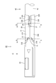
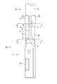
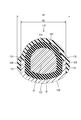
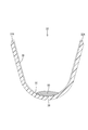
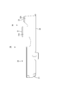
- Plan view of aluminum wire with corrosion-proof terminal AA line sectional view in FIG. BB sectional view in FIG. Plan view showing a state where anticorrosion treatment is applied to an aluminum electric wire with anticorrosion terminals CC sectional view in FIG. DD sectional view in FIG.
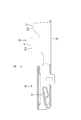
- It is sectional drawing of the conventional aluminum electric wire with a corrosion-proof terminal Comprising: Sectional drawing corresponding to FIG. Partial cutaway view of the anticorrosion terminal viewed from the side Corrosion-proof terminal development The top view which shows the state which dripped anticorrosive into the anticorrosive intrusion groove
- FIG. 15 is a cross-sectional view taken along line FF in FIG. 14 and cut at the same position as FIG.
- the anticorrosion terminal 10 in this embodiment is provided with the terminal connection part 20 which makes
- the wire connecting portion 30 is crimped to the end of the aluminum electric wire 40, and as shown in FIG. Composed.
- the anticorrosive 50 is solidified by being irradiated or UV-irradiated for a predetermined time after being dropped or sprayed in an undiluted state from above the anticorrosion terminal 10.
- the anticorrosion terminal 10 is formed by punching a base material made of a copper alloy and bending it. As shown in FIG. 8, the terminal connection portion 20 is formed in a box shape having a rectangular tube shape, and an elastic contact piece 21 is formed inside the terminal connection portion 20. The elastic contact piece 21 extends rearward from the front edge of the bottom wall of the terminal connection portion 20 and is elastically deformable. When a tab-shaped male terminal (not shown) is fitted to the anticorrosion terminal 10, the male terminal is sandwiched between the elastic contact piece 21 and the ceiling wall of the terminal connection portion 20, and the male terminal and the anticorrosion terminal 10 are electrically connected. Connected as possible.
- the electric wire connecting portion 30 includes a wire barrel 31 connected to the core wire 41 of the aluminum electric wire 40 and an insulation barrel 32 connected to the coating 42 of the aluminum electric wire 40. Further, the electric wire connection portion 30 has a bottom wall 38 that is common to the terminal connection portion 20.
- the core wire 41 is made by twisting together metal strands made of a plurality of aluminum.
- the coating 42 is made of an insulating resin. The core wire 41 is exposed by peeling the coating 42 at the end of the aluminum electric wire 40, and the wire barrel 31 is crimped to the core wire 41 so as to be conductive, and the insulation barrel 32 is crimped to the coating 42. .
- the wire barrel 31 has a pair of wire barrel pieces 31A rising from both side edges of the bottom wall 38 common to the terminal connecting portion 20, and the wire barrel pieces 31A are bitten into the core wire 41 while being wound inwardly. Then, it is crimped to the core wire 41.
- the insulation barrel 32 has a pair of insulation barrel pieces 32A rising from both side edges of the bottom wall 38 common to the terminal connecting portion 20, and these insulation barrel pieces 32A are arranged along the outer peripheral surface of the covering 42. In this manner, the cover 42 is pressure-bonded. As shown in FIG. 1, the tips of the insulation barrel pieces 32 ⁇ / b> A after crimping are arranged with a predetermined gap in a form that does not overlap each other.
- a pair of storage portions 33 and 34 are formed on both front and rear sides of the wire barrel 31.
- the storage part located in the front side is referred to as the front storage part 33
- the storage part located in the rear side is referred to as the rear storage part 34.
- a bell mouth is not formed at the front end of the wire barrel 31
- a bell mouth 37 is formed at the rear end of the wire barrel 31 at the time of crimping.
- a taper shape is formed such that an upward slope is formed from the rear end portion of the barrel 31 toward the rear.
- the wire barrel 31 and the insulation barrel 32 are continuously formed without a break in a side view, and a rear storage portion 34 is formed in this continuous portion.
- the rear reservoir 34 extends rearward as it is from the end of the base material exposed at the rear end of the bell mouth 37.
- the front storage portion 33 has a concave shape with an upper surface opening surrounded by the distal end portion 31 ⁇ / b> B of the pair of left and right wire barrel pieces 31 ⁇ / b> A and the upper portion 41 ⁇ / b> A of the core wire 41.
- Each wire barrel piece 31A is arranged in a form in which the core wire 41 is wound, and the distal end portion 31B of each wire barrel piece 31A is arranged inwardly in the upper portion 41A of the core wire 41, and the base end portion 31C is all the core wire 41.
- the two side portions 41B are arranged extending in the vertical direction. Further, the distal end portion 31B of each wire barrel piece 31A faces in the left-right direction, and all of them are arranged substantially orthogonal to the upper portion 41A of the core wire 41.
- the anticorrosive agent 50 when the anticorrosive agent 50 is dripped at the front side storage part 33, as shown in FIG. 5, most of the anticorrosive agent 50 is stored in the front side storage part 33, and the anticorrosive 50 overflowing from this front side storage part 33 is also included. It is fastened to the distal end portion 31B and does not flow out to the proximal end portion 31C. That is, since the anticorrosive 50 applied to the wire barrel 31 is disposed in the region R1 narrower than the maximum width region W1 on the upper surface of the wire barrel 31, the wire barrel 31 is not enlarged by the anticorrosive 50.
- the rear storage part 34 has a concave shape with an upper surface opening surrounded by a tip part 32 ⁇ / b> B of a pair of left and right insulation barrel pieces 32 ⁇ / b> A and an upper part 42 ⁇ / b> A of the covering 42.
- Each insulation barrel piece 32A is arranged in such a manner as to enclose the coating 42, and the distal end portion 32B of each insulation barrel piece 32A is arranged inwardly in the upper portion 42A of the coating 42, and the base end portion 32C is all covered.
- the two side portions 42B of 42 are arranged extending in the vertical direction.
- the tip 32B of each insulation barrel piece 32A is opposed in the left-right direction, and all of them are arranged so as to be substantially orthogonal to the upper part 42A of the covering 42.
- the anticorrosive agent 50 when the anticorrosive agent 50 is dripped at the rear side storage part 34, as shown in FIG. 6, most of the anticorrosive agent 50 is stored in the rear side storage part 34, and the anticorrosion overflowed from this rear side storage part 34
- the agent 50 is also fastened to the distal end portion 32B and does not flow out to the proximal end portion 32C. That is, since the anticorrosive 50 applied to the insulation barrel 32 is disposed in the region R2 narrower than the maximum width region W2 on the upper surface of the insulation barrel 32, the insulation barrel 32 is enlarged by the anticorrosive 50. There is no.
- the effect of the anticorrosion terminal 10 of this embodiment is demonstrated, comparing with the conventional anticorrosion terminal 110 shown in FIG.
- the electric wire connection portion 130 is not provided with a storage portion for storing the anticorrosive agent 150. That is, the front end portion 132 of the barrel piece 131 is arranged facing upward at both side portions 42 ⁇ / b> B of the coating 42. For this reason, the anticorrosive agent 150 dropped onto the upper part 42A of the coating 42 flows down along the upper part 42A of the coating 42, and exceeds the front end part 132 of the barrel piece 131 disposed on the both side parts 42B of the coating 42. By reaching 133, the anticorrosion terminal 110 is covered over the entire circumference.
- the anticorrosive 150 is formed in the region R3 wider than the maximum width region W3 on the upper surface of the electric wire connecting portion 130, and the electric wire connecting portion 130 is enlarged once by the anticorrosive 150.
- the wire connecting portion 30 (the insulation barrel 32 is illustrated in FIG. 6) is not covered by the anticorrosive 50 over the entire circumference.
- the wire connection part 30 can be reduced in size in the left-right direction as much as the anticorrosive 50 is eliminated.
- a plurality of anticorrosive agent intrusion grooves 36 are formed on the pressure-bonding surface (surface on the near side in FIG. 9) 35 of the insulation barrel 32.
- the anticorrosive agent intrusion groove 36 in the unfolded state is formed to extend linearly in an arrangement perpendicular to the axial direction of the aluminum electric wire 40.
- the insulation barrel 32 is formed in a substantially U shape, and accordingly, the anticorrosive agent intrusion groove 36 is also formed in a substantially U shape.
- both end portions of the anticorrosive agent intrusion groove 36 are closed without opening at the distal end portion of the insulation barrel piece 32 ⁇ / b> A.
- an anticorrosive 50 is applied to the crimping surface 35 of the insulation barrel 32 in advance.
- the anticorrosive agent 50 is applied to the region including the anticorrosive agent intrusion grooves 36 in the pressure-bonding surface 35.
- the anticorrosion agent 50 pushed by the coating 42 moves along the anticorrosion agent intrusion groove 36.
- the anticorrosive agent intrusion groove 36 is filled with the anticorrosive agent 50 after spreading in the circumferential direction.
- the anticorrosive agent 50 can be reliably interposed between the crimping surface 35 of the insulation barrel 32 and the coating 42, and the crimping surface 35 and the coating of the insulation barrel 32 from the rear of the insulation barrel 32. It is possible to prevent water from entering the interface between the core wire 41 and the wire barrel 31 through the interface with 42, thereby preventing electrolytic corrosion.
- the anticorrosive agent 50 is dropped and partially applied to the crimping surface 35 of the insulation barrel 32, and UV irradiation is performed as necessary. Perform (application process before pressure bonding). As a result, as shown in FIGS. 5 and 6, the anticorrosive agent 50 is stored in the storage portions 33 and 34, and in the regions R1 and R2 narrower than the maximum width regions W1 and W2 on the upper surface of the wire connection portion 30. Arranged.
- the end of the aluminum electric wire 40 is placed on the electric wire connecting portion 30.
- the core wire 41 is disposed on the wire barrel 31, and the coating 42 is disposed on the insulation barrel 32.
- the wire connecting portion 30 is crimped, the wire barrel 31 is crimped to the core wire 41, and the core wire 41 bites into the knurled serration formed on the crimp surface of the wire barrel 31, so that the oxide film on the surface of the core wire 41 is destroyed. Conduction is taken.
- the insulation barrel 32 is pressure-bonded to the coating 42, the anticorrosive agent 50 is filled in the anticorrosive agent intrusion groove 36, and is applied to the entire pressure-bonding surface 35 (crimping step).
- the front storage part 33 and the rear storage part 34 are formed.
- the anticorrosive agent 50 of the quantity required for the front side storage part 33 and the back side storage part 34 is dripped and apply
- the anticorrosive agent 50 is cured in a state of being fastened to the upper surface of the wire connection portion 30, and the wire connection portion 30 becomes larger than the maximum width regions W ⁇ b> 1 and W ⁇ b> 2 of the barrels 31 and 32. I don't have to.
- each storage part 33, 34 is formed by being surrounded by a copper alloy exposed by punching a base material plated with tin on the surface of a base material made of a copper alloy, each storage part 33, 34 is formed.
- the anticorrosive 50 dripped onto the inevitably comes into contact with the exposed copper alloy, and the exposed surface of the exposed copper alloy can be efficiently sealed with the anticorrosive 50.
- a part of the copper alloy is concentrated in one place, it is not necessary to cover the entire wire connection portion 30 with the anticorrosive 50, and the application of the anticorrosive 50 can be minimized.
- the anticorrosive agent 50 is applied in advance to the surface of the insulation barrel 32 that is in contact with the coating 42 (crimp surface 35), the insulation barrel 32 is applied when crimping is performed. And the coating 42 of the aluminum electric wire 40 can be filled with the anticorrosive 50. Therefore, the corrosion protection agent 50 can be reliably interposed between the insulation barrel 32 and the aluminum electric wire 40 to prevent electrolytic corrosion.
- An anticorrosive intrusion groove 36 extending in a direction intersecting the axial direction of the aluminum electric wire 40 is formed on a surface (crimp surface 35) of the insulation barrel 32 on the side in contact with the coating 42, and the insulation barrel 32 is covered with the coating 42.
- the anticorrosive agent 50 may be filled in the anticorrosive agent intrusion groove 36 in a state where the anticorrosive agent is pressed onto the anticorrosive agent. According to such a configuration, since the anticorrosive agent intrusion groove 36 is filled with the anticorrosive agent 50 in a crimped state, the anticorrosive agent 50 can be reliably interposed between the insulation barrel 32 and the aluminum electric wire 40. it can.
- the insulation barrel 32 includes a bottom wall 38 and a pair of insulation barrel pieces 32A rising from both side edges of the bottom wall 38, and the anticorrosive intrusion groove 36 is formed at the tip of the pair of insulation barrel pieces 32A. It is good also as a structure closed in the part 32B. According to such a configuration, the anticorrosive agent 50 can be applied over substantially the entire circumferential direction of the insulation barrel 32. Moreover, since the anticorrosive agent intrusion groove 36 is not opened at the tip portion 32B of the insulation barrel piece 32A, there is no possibility that the anticorrosive agent 50 overflows from the tip of the insulation barrel 32 due to pressure bonding. The anticorrosive agent 50 can be kept between the aluminum electric wire 40.
- the anticorrosive agent 50 may be configured to move along the anticorrosive agent intrusion groove 36 and expand in the circumferential direction as the aluminum wire 40 is crimped. According to such a configuration, it is not necessary to apply the anticorrosive agent 50 on the entire surface of the insulation barrel 32 on the side in contact with the coating 42 (crimping surface 35). Since the agent 50 spreads in the circumferential direction through the anticorrosive agent intrusion groove 36, the anticorrosive agent 50 can be filled between the insulation barrel 32 and the coating 42 of the aluminum electric wire 40.
- the present invention includes the above-described anticorrosion terminal 10 and an aluminum electric wire 40 connected to the anticorrosion terminal 10, and a cover 42 of the aluminum electric wire 40 is placed on the insulation barrel 32 so as to be in contact with the anticorrosive agent 50. Then, the anticorrosion terminal-attached aluminum electric wire 60 in which the anticorrosion agent 50 is further applied to the insulation barrel 32 after crimping may be used.
- the present invention includes a pre-compression application step in which an anticorrosive agent 50 is applied in advance to the crimping surface 35 of the insulation barrel 32 of the anticorrosion terminal 10 including the wire barrel 31 and the insulation barrel 32, and a coating 42 of the aluminum wire 40.
- the crimping is performed by being placed on the insulation barrel 32 so that the anticorrosive 50 is filled between the coating 42 of the aluminum electric wire 40 and the insulation barrel 32, and the insulation barrel 32 after crimping is anticorrosive. It is good also as a manufacturing method of the aluminum electric wire 60 with an anticorrosion terminal provided with the post-crimping application
- thermosetting or thermoplastic anticorrosive may be used.
- the number of anticorrosive agent intrusion grooves may be one, or 3 It may be more than the article. Or it is good also as a structure which does not provide an anticorrosive agent penetration groove
- the anticorrosive intrusion groove 36 is closed by the tip 32B of the insulation barrel piece 32A in the above embodiment, according to the present invention, the anticorrosive intrusion groove may be open.
- a covered electric wire having a core wire composed of a plurality of metal strands has been exemplified.
- the core wire is formed of one metal strand having a relatively large diameter, that is, a single core It is good also as a type
- the above embodiment illustrates the configuration in which the corrosion prevention terminal 10 made of copper alloy is connected to the aluminum electric wire 40, the core wire of the coated electric wire and the corrosion prevention terminal connected thereto are formed of different kinds of metals. Other materials may be used as long as they are present. For example, copper having excellent strength may be used as a constituent material of the anticorrosion terminal.
Landscapes
- Engineering & Computer Science (AREA)
- Manufacturing & Machinery (AREA)
- Connections Effected By Soldering, Adhesion, Or Permanent Deformation (AREA)
- Manufacturing Of Electrical Connectors (AREA)
Abstract
Description
インシュレーションバレルのうち被覆に接する側の面に、被覆電線の軸線方向と交差する方向に延びる防食剤浸入溝が形成されており、インシュレーションバレルが被覆に圧着された状態では防食剤が防食剤浸入溝に充填される構成としてもよい。
このような構成によると、圧着状態で防食剤浸入溝に防食剤が充填されるようにしたから、インシュレーションバレルと被覆電線との間に確実に防食剤を介在させることができる。
このような構成によると、インシュレーションバレルの周方向のほぼ全域に亘って防食剤を塗布することができる。また、バレル片の先端部に防食剤浸入溝が開口していないため、圧着に伴ってバレルの先端から防食剤が溢れ出すおそれはなく、インシュレーションバレルと被覆電線との間に防食剤を留めておくことができる。
このような構成によると、インシュレーションバレルのうち被覆に接する側の面に対して防食剤を全面に塗布しておく必要はなく、圧着を行った際に、防食剤が防食剤浸入溝を通って周方向に広がるため、インシュレーションバレルと被覆電線の被覆との間に防食剤を充填させることができる。
本発明の実施形態を図1ないし図15の図面を参照しながら説明する。本実施形態における防食端子10は、図8に示すように、角筒形状をなす端子接続部20と、この端子接続部20の後方に形成された電線接続部30とを備えている。図1に示すように、電線接続部30がアルミ電線40の端末に圧着され、図4に示すように、電線接続部30に防食剤50が塗布されることにより、防食端子付きアルミ電線60が構成される。防食剤50は、防食端子10の上方から原液状態で滴下または散布された後、所定時間UV照射を行うことにより固化される。
本発明は上記記述及び図面によって説明した実施形態に限定されるものではなく、例えば次のような実施形態も本発明の技術的範囲に含まれる。
(1)上記実施形態では防食端子10として端子接続部20を有する雌端子を例示しているものの、本発明は、タブ状をなす接続部を有する雄端子に適用してもよい。
30…電線接続部
31…ワイヤバレル
32…インシュレーションバレル
32A…インシュレーションバレル片
32B…先端部
35…圧着面(インシュレーションバレルのうち被覆に接する側の面)
36…防食剤浸入溝
38…底壁
40…アルミ電線(被覆電線)
41…芯線
42…被覆
50…防食剤
60…防食端子付きアルミ電線
Claims (6)
- 芯線が被覆で覆われてなる被覆電線に圧着される前の防食端子であって、
前記被覆を皮剥ぎすることで露出された芯線に圧着されるワイヤバレルと、
前記被覆に圧着されるインシュレーションバレルと、
前記インシュレーションバレルのうち前記被覆に接する側の面に予め塗布された防食剤とを備えた防食端子。 - 前記インシュレーションバレルのうち前記被覆に接する側の面に、前記被覆電線の軸線方向と交差する方向に延びる防食剤浸入溝が形成されており、前記インシュレーションバレルが前記被覆に圧着された状態では前記防食剤が前記防食剤浸入溝に充填されることを特徴とする請求項1に記載の防食端子。
- 前記インシュレーションバレルは、底壁と、この底壁の両側縁から立ち上がる一対のバレル片とを備えて構成され、前記防食剤浸入溝は、一対の前記バレル片の先端部において閉じられていることを特徴とする請求項2に記載の防食端子。
- 前記防食剤は、前記被覆電線への圧着に伴って前記防食剤浸入溝に沿って移動して周方向に広がることを特徴とする請求項2または請求項3に記載の防食端子。
- 請求項1ないし請求項4のいずれか一項に記載の防食端子と、
この防食端子に接続された前記被覆電線とを備え、
前記防食剤に接するように前記被覆電線の被覆を前記インシュレーションバレルに載せて圧着が行われた後、圧着後の前記インシュレーションバレルに対して前記防食剤がさらに塗布されたことを特徴とする防食端子付き電線。 - ワイヤバレルとインシュレーションバレルを備えた防食端子の前記インシュレーションバレルの圧着面に予め防食剤を塗布する圧着前塗布工程と、
前記被覆電線の被覆を前記インシュレーションバレルの圧着面に載せて圧着が行われることで、前記防食剤を前記被覆電線の被覆と前記インシュレーションバレルとの間に充填させる圧着工程と、
圧着後の前記インシュレーションバレルに対して前記防食剤をさらに塗布する圧着後塗布工程とを備えた防食端子付き電線の製造方法。
Priority Applications (2)
| Application Number | Priority Date | Filing Date | Title |
|---|---|---|---|
| US14/770,157 US9570840B2 (en) | 2013-03-15 | 2014-03-12 | Corrosion-resistant terminal, wire with corrosion-resistant terminal and method for producing wire with corrosion-resistant terminal |
| CN201480014019.XA CN105190999A (zh) | 2013-03-15 | 2014-03-12 | 防蚀端子、带防蚀端子的电线、及带防蚀端子的电线的制造方法 |
Applications Claiming Priority (2)
| Application Number | Priority Date | Filing Date | Title |
|---|---|---|---|
| JP2013-052971 | 2013-03-15 | ||
| JP2013052971A JP2014179260A (ja) | 2013-03-15 | 2013-03-15 | 防食端子、防食端子付き電線、および防食端子付き電線の製造方法 |
Publications (1)
| Publication Number | Publication Date |
|---|---|
| WO2014142155A1 true WO2014142155A1 (ja) | 2014-09-18 |
Family
ID=51536806
Family Applications (1)
| Application Number | Title | Priority Date | Filing Date |
|---|---|---|---|
| PCT/JP2014/056443 Ceased WO2014142155A1 (ja) | 2013-03-15 | 2014-03-12 | 防食端子、防食端子付き電線、および防食端子付き電線の製造方法 |
Country Status (4)
| Country | Link |
|---|---|
| US (1) | US9570840B2 (ja) |
| JP (1) | JP2014179260A (ja) |
| CN (1) | CN105190999A (ja) |
| WO (1) | WO2014142155A1 (ja) |
Cited By (1)
| Publication number | Priority date | Publication date | Assignee | Title |
|---|---|---|---|---|
| WO2017212920A1 (ja) * | 2016-06-09 | 2017-12-14 | 株式会社オートネットワーク技術研究所 | 端子付き電線 |
Families Citing this family (4)
| Publication number | Priority date | Publication date | Assignee | Title |
|---|---|---|---|---|
| JP2016164836A (ja) * | 2015-03-06 | 2016-09-08 | 株式会社オートネットワーク技術研究所 | 端子付き電線及び端子 |
| JP7233971B2 (ja) * | 2019-03-04 | 2023-03-07 | 矢崎総業株式会社 | 端子付き電線製造方法、及び、端子付き電線製造装置 |
| JP6976989B2 (ja) * | 2019-05-21 | 2021-12-08 | 矢崎総業株式会社 | 端子付き電線、塗布装置、および端子付き電線の製造方法 |
| US11588255B2 (en) * | 2020-07-14 | 2023-02-21 | Yazaki Corporation | Electric wire with terminal having improved anticorrosion performance |
Citations (6)
| Publication number | Priority date | Publication date | Assignee | Title |
|---|---|---|---|---|
| JP2010165514A (ja) * | 2009-01-14 | 2010-07-29 | Autonetworks Technologies Ltd | 連鎖端子、端子金具、及び端子金具の製造方法 |
| JP2011018489A (ja) * | 2009-07-08 | 2011-01-27 | Furukawa Electric Co Ltd:The | 端子構造、導体と端子の接続部および接続方法 |
| JP2011192530A (ja) * | 2010-03-15 | 2011-09-29 | Autonetworks Technologies Ltd | 端子金具、及び端子金具付き電線 |
| JP2011204582A (ja) * | 2010-03-26 | 2011-10-13 | Sumitomo Wiring Syst Ltd | 電線付き端子金具 |
| JP2013080682A (ja) * | 2011-10-05 | 2013-05-02 | Furukawa Electric Co Ltd:The | 圧着端子、接続構造体及びコネクタ |
| JP2013235716A (ja) * | 2012-05-09 | 2013-11-21 | Auto Network Gijutsu Kenkyusho:Kk | 端子付電線 |
Family Cites Families (2)
| Publication number | Priority date | Publication date | Assignee | Title |
|---|---|---|---|---|
| US7954235B2 (en) * | 2009-09-18 | 2011-06-07 | Delphi Technologies, Inc. | Method of making a seal about a copper-based terminal |
| JP2011096451A (ja) * | 2009-10-28 | 2011-05-12 | Yazaki Corp | 圧着端子 |
-
2013
- 2013-03-15 JP JP2013052971A patent/JP2014179260A/ja active Pending
-
2014
- 2014-03-12 WO PCT/JP2014/056443 patent/WO2014142155A1/ja not_active Ceased
- 2014-03-12 US US14/770,157 patent/US9570840B2/en not_active Expired - Fee Related
- 2014-03-12 CN CN201480014019.XA patent/CN105190999A/zh active Pending
Patent Citations (6)
| Publication number | Priority date | Publication date | Assignee | Title |
|---|---|---|---|---|
| JP2010165514A (ja) * | 2009-01-14 | 2010-07-29 | Autonetworks Technologies Ltd | 連鎖端子、端子金具、及び端子金具の製造方法 |
| JP2011018489A (ja) * | 2009-07-08 | 2011-01-27 | Furukawa Electric Co Ltd:The | 端子構造、導体と端子の接続部および接続方法 |
| JP2011192530A (ja) * | 2010-03-15 | 2011-09-29 | Autonetworks Technologies Ltd | 端子金具、及び端子金具付き電線 |
| JP2011204582A (ja) * | 2010-03-26 | 2011-10-13 | Sumitomo Wiring Syst Ltd | 電線付き端子金具 |
| JP2013080682A (ja) * | 2011-10-05 | 2013-05-02 | Furukawa Electric Co Ltd:The | 圧着端子、接続構造体及びコネクタ |
| JP2013235716A (ja) * | 2012-05-09 | 2013-11-21 | Auto Network Gijutsu Kenkyusho:Kk | 端子付電線 |
Cited By (1)
| Publication number | Priority date | Publication date | Assignee | Title |
|---|---|---|---|---|
| WO2017212920A1 (ja) * | 2016-06-09 | 2017-12-14 | 株式会社オートネットワーク技術研究所 | 端子付き電線 |
Also Published As
| Publication number | Publication date |
|---|---|
| US9570840B2 (en) | 2017-02-14 |
| JP2014179260A (ja) | 2014-09-25 |
| CN105190999A (zh) | 2015-12-23 |
| US20160006168A1 (en) | 2016-01-07 |
Similar Documents
| Publication | Publication Date | Title |
|---|---|---|
| JP5885037B2 (ja) | 防食端子付き電線 | |
| US8802987B2 (en) | Electric wire equipped with terminal fitting and method of manufacturing the same | |
| JP5606127B2 (ja) | 圧着端子の電線に対する接続構造 | |
| JP5884986B2 (ja) | 圧着端子付きアルミ電線 | |
| JP5418332B2 (ja) | 端子金具付き電線 | |
| JP5789136B2 (ja) | 電気接続端子 | |
| JP5914942B2 (ja) | 端子付きアルミ電線 | |
| KR20150102981A (ko) | 압착 단자를 갖는 알루미늄 전선 및 그 제조 방법 | |
| US9608339B2 (en) | Crimped terminal attached aluminum electric wire | |
| JP2013246886A (ja) | 端子付き電線およびその製造方法、ならびに治具 | |
| WO2013111465A1 (ja) | 端子金具 | |
| WO2014142155A1 (ja) | 防食端子、防食端子付き電線、および防食端子付き電線の製造方法 | |
| JP6996974B2 (ja) | 端子付き電線および端子付き電線の製造方法 | |
| JP5971513B2 (ja) | 端子付き電線およびその製造方法 | |
| JP6598654B2 (ja) | 端子付き電線 | |
| JP2013246883A (ja) | 端子金具 | |
| JP2014191989A (ja) | 端子付電線 | |
| JP2016046220A (ja) | 端子付き電線及びその製造方法 | |
| JP2013196841A (ja) | 圧着端子を電線に圧着する方法 | |
| JP2020181698A (ja) | 端子付き電線、及び、端子金具 | |
| WO2016167120A1 (ja) | 端子および端子付き電線 |
Legal Events
| Date | Code | Title | Description |
|---|---|---|---|
| WWE | Wipo information: entry into national phase |
Ref document number: 201480014019.X Country of ref document: CN |
|
| 121 | Ep: the epo has been informed by wipo that ep was designated in this application |
Ref document number: 14764279 Country of ref document: EP Kind code of ref document: A1 |
|
| WWE | Wipo information: entry into national phase |
Ref document number: 14770157 Country of ref document: US |
|
| NENP | Non-entry into the national phase |
Ref country code: DE |
|
| 122 | Ep: pct application non-entry in european phase |
Ref document number: 14764279 Country of ref document: EP Kind code of ref document: A1 |