WO2014141850A1 - エンジン作業機の表示装置 - Google Patents
エンジン作業機の表示装置 Download PDFInfo
- Publication number
- WO2014141850A1 WO2014141850A1 PCT/JP2014/054070 JP2014054070W WO2014141850A1 WO 2014141850 A1 WO2014141850 A1 WO 2014141850A1 JP 2014054070 W JP2014054070 W JP 2014054070W WO 2014141850 A1 WO2014141850 A1 WO 2014141850A1
- Authority
- WO
- WIPO (PCT)
- Prior art keywords
- engine
- display
- meter
- load factor
- unit
- Prior art date
- Legal status (The legal status is an assumption and is not a legal conclusion. Google has not performed a legal analysis and makes no representation as to the accuracy of the status listed.)
- Ceased
Links
Images


Classifications
-
- A—HUMAN NECESSITIES
- A01—AGRICULTURE; FORESTRY; ANIMAL HUSBANDRY; HUNTING; TRAPPING; FISHING
- A01D—HARVESTING; MOWING
- A01D41/00—Combines, i.e. harvesters or mowers combined with threshing devices
- A01D41/12—Details of combines
-
- B—PERFORMING OPERATIONS; TRANSPORTING
- B60—VEHICLES IN GENERAL
- B60K—ARRANGEMENT OR MOUNTING OF PROPULSION UNITS OR OF TRANSMISSIONS IN VEHICLES; ARRANGEMENT OR MOUNTING OF PLURAL DIVERSE PRIME-MOVERS IN VEHICLES; AUXILIARY DRIVES FOR VEHICLES; INSTRUMENTATION OR DASHBOARDS FOR VEHICLES; ARRANGEMENTS IN CONNECTION WITH COOLING, AIR INTAKE, GAS EXHAUST OR FUEL SUPPLY OF PROPULSION UNITS IN VEHICLES
- B60K35/00—Instruments specially adapted for vehicles; Arrangement of instruments in or on vehicles
- B60K35/20—Output arrangements, i.e. from vehicle to user, associated with vehicle functions or specially adapted therefor
- B60K35/21—Output arrangements, i.e. from vehicle to user, associated with vehicle functions or specially adapted therefor using visual output, e.g. blinking lights or matrix displays
- B60K35/215—Output arrangements, i.e. from vehicle to user, associated with vehicle functions or specially adapted therefor using visual output, e.g. blinking lights or matrix displays characterised by the combination of multiple visual outputs, e.g. combined instruments with analogue meters and additional displays
-
- B—PERFORMING OPERATIONS; TRANSPORTING
- B60—VEHICLES IN GENERAL
- B60K—ARRANGEMENT OR MOUNTING OF PROPULSION UNITS OR OF TRANSMISSIONS IN VEHICLES; ARRANGEMENT OR MOUNTING OF PLURAL DIVERSE PRIME-MOVERS IN VEHICLES; AUXILIARY DRIVES FOR VEHICLES; INSTRUMENTATION OR DASHBOARDS FOR VEHICLES; ARRANGEMENTS IN CONNECTION WITH COOLING, AIR INTAKE, GAS EXHAUST OR FUEL SUPPLY OF PROPULSION UNITS IN VEHICLES
- B60K35/00—Instruments specially adapted for vehicles; Arrangement of instruments in or on vehicles
- B60K35/20—Output arrangements, i.e. from vehicle to user, associated with vehicle functions or specially adapted therefor
- B60K35/21—Output arrangements, i.e. from vehicle to user, associated with vehicle functions or specially adapted therefor using visual output, e.g. blinking lights or matrix displays
- B60K35/22—Display screens
-
- B—PERFORMING OPERATIONS; TRANSPORTING
- B60—VEHICLES IN GENERAL
- B60K—ARRANGEMENT OR MOUNTING OF PROPULSION UNITS OR OF TRANSMISSIONS IN VEHICLES; ARRANGEMENT OR MOUNTING OF PLURAL DIVERSE PRIME-MOVERS IN VEHICLES; AUXILIARY DRIVES FOR VEHICLES; INSTRUMENTATION OR DASHBOARDS FOR VEHICLES; ARRANGEMENTS IN CONNECTION WITH COOLING, AIR INTAKE, GAS EXHAUST OR FUEL SUPPLY OF PROPULSION UNITS IN VEHICLES
- B60K35/00—Instruments specially adapted for vehicles; Arrangement of instruments in or on vehicles
- B60K35/20—Output arrangements, i.e. from vehicle to user, associated with vehicle functions or specially adapted therefor
- B60K35/28—Output arrangements, i.e. from vehicle to user, associated with vehicle functions or specially adapted therefor characterised by the type of the output information, e.g. video entertainment or vehicle dynamics information; characterised by the purpose of the output information, e.g. for attracting the attention of the driver
-
- G—PHYSICS
- G01—MEASURING; TESTING
- G01D—MEASURING NOT SPECIALLY ADAPTED FOR A SPECIFIC VARIABLE; ARRANGEMENTS FOR MEASURING TWO OR MORE VARIABLES NOT COVERED IN A SINGLE OTHER SUBCLASS; TARIFF METERING APPARATUS; MEASURING OR TESTING NOT OTHERWISE PROVIDED FOR
- G01D7/00—Indicating measured values
- G01D7/02—Indicating value of two or more variables simultaneously
- G01D7/04—Indicating value of two or more variables simultaneously using a separate indicating element for each variable
- G01D7/06—Luminous indications projected on a common screen
-
- B—PERFORMING OPERATIONS; TRANSPORTING
- B60—VEHICLES IN GENERAL
- B60K—ARRANGEMENT OR MOUNTING OF PROPULSION UNITS OR OF TRANSMISSIONS IN VEHICLES; ARRANGEMENT OR MOUNTING OF PLURAL DIVERSE PRIME-MOVERS IN VEHICLES; AUXILIARY DRIVES FOR VEHICLES; INSTRUMENTATION OR DASHBOARDS FOR VEHICLES; ARRANGEMENTS IN CONNECTION WITH COOLING, AIR INTAKE, GAS EXHAUST OR FUEL SUPPLY OF PROPULSION UNITS IN VEHICLES
- B60K2360/00—Indexing scheme associated with groups B60K35/00 or B60K37/00 relating to details of instruments or dashboards
- B60K2360/1523—Matrix displays
-
- B—PERFORMING OPERATIONS; TRANSPORTING
- B60—VEHICLES IN GENERAL
- B60Y—INDEXING SCHEME RELATING TO ASPECTS CROSS-CUTTING VEHICLE TECHNOLOGY
- B60Y2200/00—Type of vehicle
- B60Y2200/20—Off-Road Vehicles
- B60Y2200/22—Agricultural vehicles
- B60Y2200/222—Harvesters
Definitions
- the present invention relates to a display device for an engine work machine.
- a display device for displaying the operating state of an engine work machine such as a combine is known. Not only the traveling speed of the engine working machine, the engine rotation speed, the engine load factor, and the working state of the working machine but also various warnings are displayed.
- a tractor that displays different images on a display device (monitor unit) provided in a cockpit for each work device (work machine) to be connected.
- a display device monitoror unit
- the engine work machine displays a tachometer to manage the engine speed, but it may be more appropriate to work based on the engine load factor during work.
- the display device described in Patent Literature 1 does not disclose a configuration that automatically switches between the display of the rotation speed and the display of the load factor in accordance with the work state. For this reason, it is necessary to separately perform an operation for displaying the load factor on the display device or to check a separately installed load factor meter.
- the present invention has been made to solve such a problem, and an object of the present invention is to provide a display device for an engine work machine that can acquire engine information suitable for a working state without performing a specific operation. To do.
- the engine tachometer and the engine load factor meter are configured with different figures, respectively, and based on the working state of the engine work machine A rotation speed meter and a load factor meter are selectively switched and displayed.
- the display of the tachometer and the display of the load factor meter are switched based on the operation of a predetermined operation tool.
- the information displayed in conjunction with the operation of the operation tool is switched. As a result, it is possible to acquire engine information suitable for the working state without performing a specific operation.
- the working machine provided with the display device 27 is not limited to the present embodiment, and may be a working machine such as a tractor or a back fore.
- the combine 1 includes a traveling unit 2, a cutting unit 5 as a working device, a threshing unit 9, a sorting unit 10, a grain storage unit 11, and a maneuvering unit.
- a unit 14 and the like are provided.
- the traveling unit 2 travels the aircraft in the forward or reverse direction.
- the traveling unit 2 is provided in the lower part of the body frame 3.
- the traveling unit 2 includes a crawler traveling device 4 having a pair of left and right crawlers.
- the traveling unit 2 is provided with a traveling speed sensor 20 that detects the traveling speed of the aircraft (see FIG. 2).
- the mowing unit 5 is for harvesting cereal grains in the field.
- the cutting unit 5 is provided at the front end of the machine body frame 3 (front part of the machine body) so as to be movable up and down with respect to the machine body.
- the reaping unit 5 causes the culm in the field to be caused by the pulling device 6, cuts the root of the culm after the pulling by the cutting device 7, and conveys the cut culm to the threshing unit 9 side by the cutting device 8. Configured.
- the threshing unit 9 threshs the cereal.
- the threshing unit 9 is provided on the left front side of the machine body frame 3 and behind the cutting unit 5.
- the threshing unit 9 is configured to inherit the cereals conveyed from the cutting unit 5, thresh the cereals being conveyed by the handling cylinder and the like, and drop the threshing processed product to the sorting unit 10.
- the threshing section 9 is provided with a threshing section load sensor 24 that detects the load of the threshing section 9 (see FIG. 2).
- the sorting unit 10 sorts cereals into grains and wastes.
- the sorting unit 10 is provided on the left side of the machine body frame 3 and below the threshing unit 9.
- the sorting unit 10 sorts the processed material dropped from the threshing unit 9 into grains, spiked grains, unthreshed grains, waste, dust, and the like by a rocking sorter and a wind sorter using a rocking sorter.
- the sorting unit 10 is configured to convey the selected grain to the grain storage unit 11, to carry the spiked grains and the unthreshed grains to the threshing unit 9, and to discharge waste and dust to the outside. .
- the sorting unit 10 is provided with a sorting unit load sensor 25 that detects the load of the sorting unit 10 (see FIG. 2).
- Kernel storage unit 11 stores threshed and selected kernels.
- the grain storage unit 11 is provided on the right side of the machine body frame 3 on the right side of the threshing unit 9 and the sorting unit 10.
- the grain storage unit 11 includes a Glen tank 12, a grain discharging device 13, and the like.
- the grain storage unit 11 stores the grain conveyed from the sorting unit 10 in the grain tank 12 and discharges the grain stored in the grain tank 12 to the outside of the machine body by the grain discharging device 13. Composed.
- the Glen tank 12 is provided with a weight sensor 23 for detecting the amount of stored grain (see FIG. 2).
- the steering unit 14 is operated by the operator.
- the control unit 14 is provided on the right front side of the body frame 3 and on the right side of the cutting unit 5.
- an operation tool 17 for operating the combine 1 and a display device 27 are arranged around the cockpit 16 in the cabin 15.
- the operation tool 17 includes an accelerator operation tool for controlling the fuel injection amount, an operation tool for adjusting the left and right height and the front and rear height of the combine 1, and an operation tool for operating each working device such as the cutting unit 5 and the threshing unit 9. It is.
- the operation tool 17 includes an operation amount detection sensor 17a that detects an operation amount of each operation tool.
- ECU19 (refer FIG. 2) which controls the engine 18 and each work apparatus with the signal from the operation amount detection sensor 17a is provided.
- the ECU 19 controls the engine 18 and various working devices.
- the ECU 19 stores various programs for controlling the engine 18, each work device, and the like. Further, the ECU 19 can perform predetermined calculations according to these programs and the like, and can store the results of the calculations.
- the ECU 19 may actually be configured such that a CPU, ROM, RAM, HDD, or the like is connected by a bus, or may be configured by a one-chip LSI or the like.
- the ECU 19 is connected to the traveling speed sensor 20 of the airframe and the rotational speed sensor 21 of the engine 18, and can acquire the traveling speed detected by the traveling speed sensor 20 and the rotational speed sensor 21 and the rotational speed of the engine 18. It is.
- the ECU 19 is connected to the fuel fuel gauge 22 and can acquire the fuel remaining quantity in a fuel tank (not shown) detected by the fuel fuel gauge 22.
- ECU19 is connected to the weight sensor 23 of the Glen tank 12, and can acquire the signal from the weight sensor 23 of the Glen tank 12.
- the weight sensor 23 detects the internal capacity of the glen tank 12, but the present invention is not limited to this, and any apparatus capable of detecting the internal capacity may be used.
- the ECU 19 is connected to the threshing part load sensor 24 and the sorting part load sensor 25, and can acquire signals from the threshing part load sensor 24 and the sorting part load sensor 25.
- the ECU 19 is connected to the transmission 26 and can acquire a signal from the transmission 26.
- the ECU 19 is connected to the engine 18 (not shown various sensors and fuel injection devices provided in the engine 18), and can acquire signals from various sensors and control the engine 18.
- ECU19 is connected to the control apparatus 29 of the display apparatus 27, and can acquire various signals from the control apparatus 29.
- the ECU 19 is connected to the operation amount detection sensor 17a and can acquire a signal from the operation amount detection sensor 17a.
- the ECU19 memorize
- the combine 1 transmits the power of the engine 18 to each working device by operating the operation tool in the control unit 14, and the harvesting unit 5 harvests the grain culm while the traveling unit 2 travels the machine body.
- the threshing unit 9 threshs the grain from the reaping unit 5, the sorting unit 10 sorts the processed product from the threshing unit 9, and the grain storage unit 11 stores the grain from the sorting unit 10 and threshing at the same time. It is comprised so that the waste from the part 9 can be discharged
- the display device 27 displays various information related to the combine 1.
- the display device 27 includes a liquid crystal display 28 and a control device 29.
- the liquid crystal display 28 is disposed at a position where the liquid crystal display 28 is visible and operable when the operator sits on the cockpit 16 of the control unit 14 (see FIG. 1).
- the display device 27 is configured to be able to display corresponding graphics based on various signals transmitted from the control device 29.
- the liquid crystal display 28 displays characters and figures in accordance with transmitted signals and inputs signals.
- the liquid crystal display 28 may be composed of a touch panel that displays characters and figures and can input signals by touching the screen.
- the liquid crystal display 28 can display the traveling speed, the rotational speed of the engine 18, the load factor of the engine 18, the amount of stored grain, the remaining amount of fuel, the load of the threshing portion, the load of the sorting portion, the operation time, the shift display, and various alarms. Configured. Note that the characters and graphics displayed on the display face 30 of the liquid crystal display 28 are not limited to those in the present embodiment.
- a traveling speed meter 31 in which the traveling speed is displayed as a numerical value is arranged.
- a rotation speed meter 32 a on which the rotation speed of the engine 18 is displayed is disposed above the traveling speed meter 31 on the display screen 30.
- the rotation speed meter 32a is configured by a figure imitating an arc-shaped meter.
- a load factor meter 32b that displays the load factor of the engine 18 is arranged above the traveling speed meter 31 on the display screen 30 so as to switch to the rotational speed meter 32a.
- the load factor meter 32b is configured by a figure imitating a bar-shaped meter bent at an intermediate portion.
- a grain storage meter 33 On the left side of the display screen 30, a grain storage meter 33 on which the grain storage amount of the Glen tank 12 is displayed is arranged.
- the grain storage meter 33 is configured by adding a unit scale serving as a reference to a figure imitating the Glen tank 12.
- a fuel remaining amount meter 34 for displaying the fuel remaining amount is arranged on the right side of the display screen 30, a fuel remaining amount meter 34 for displaying the fuel remaining amount is arranged.
- the fuel fuel gauge 34 is configured by adding a unit scale serving as a reference to a figure imitating a level gauge in the same manner as the grain reservoir 33.
- a threshing monitor 35 and a sorting monitor 36 are arranged below the traveling speed meter 31 on the display screen 30, a threshing monitor 35 and a sorting monitor 36 are arranged.
- the threshing monitor 35 is configured such that a predetermined area can be displayed in a predetermined display color.
- the sorting monitor 36 is configured to display a predetermined area in a predetermined display color.
- an information display area 37 for displaying the operation time, the state of the transmission 26, and various alarms in numerical values and characters is arranged below the threshing monitor 35 and the sorting monitor 36 on the display screen 30, an information display area 37 for displaying the operation time, the state of the transmission 26, and various alarms in numerical values and characters is arranged.
- the liquid crystal display 28 is connected to the control device 29, and travels from the control device 29, rotation speed, load factor, grain storage amount, fuel remaining amount, threshing portion load, sorting portion load, operation time, shift display, and It is possible to obtain signals related to various alarms.
- the control device 29 controls the liquid crystal display 28.
- the control device 29 is configured integrally with or separate from the liquid crystal display 28 or the ECU 19.
- the control device 29 stores various programs for controlling the liquid crystal display 28.
- the control device 29 can perform a predetermined calculation according to these programs and the like, and can store the result of the calculation.
- the control device 29 may actually be configured such that a CPU, ROM, RAM, HDD, or the like is connected by a bus, or may be configured by a one-chip LSI or the like.
- the control device 29 is connected to the ECU 19, and signals relating to the traveling speed, rotational speed, load factor, grain storage amount, remaining fuel amount, threshing portion load, sorting portion load, operation time, speed change display, and various alarms from the ECU 19. Is possible to get.
- the control device 29 displays a liquid crystal display based on signals from the ECU 19 such as travel speed, rotation speed, load factor, grain storage amount, remaining fuel amount, threshing portion load, sorting portion load, operation time, shift display, and various alarms. It is possible to display predetermined characters, figures, etc. on the device 28. Further, the control device 29 can acquire various signals input from the liquid crystal display 28. That is, the control device 29 can display information about the combine 1 on the liquid crystal display 28 based on various signals, and can transmit an input signal from the liquid crystal display 28 to the ECU 19.
- the control device 29 relates to the travel speed, the rotation speed, the load rate, the grain storage amount, the remaining fuel amount, the threshing portion load, the sorting portion load, the operation time, the shift display, and various alarms from the ECU 19.
- the signal is acquired, the signal is transmitted so that a predetermined character, figure, or the like is displayed on the liquid crystal display 28 based on the signal.
- the traveling speed meter 31 of the liquid crystal display 28 displays the traveling speed as a numerical value based on a signal related to the traveling speed acquired from the ECU 19.
- the rotation speed is displayed by lighting the corresponding scale portion with a predetermined display color based on the signal related to the rotation speed acquired from the ECU 19.
- the load factor meter 32b of the liquid crystal display 28 displayed so as to be switched to the rotation speed meter 32a, the corresponding scale portion is lit in a predetermined display color based on the signal relating to the load factor obtained from the ECU 19. The load factor is displayed.
- the grain storage amount is displayed by lighting a figure of a predetermined display color between the corresponding unit scales based on a signal related to the grain storage amount acquired from the ECU 19. Is done.
- the fuel remaining amount indicator 34 of the liquid crystal display 28 displays the fuel remaining amount by lighting a figure of a predetermined display color between the corresponding unit scales based on a signal related to the fuel remaining amount acquired from the ECU 19. .
- the threshing portion load is displayed by lighting a figure of a predetermined display color in the corresponding area based on the signal regarding the threshing portion load acquired from the ECU 19.
- the sorting monitor 36 of the liquid crystal display 28 displays the sorting unit load by lighting a figure of a predetermined display color in a corresponding area based on a signal related to the sorting unit load acquired from the ECU 19.
- predetermined information is displayed in the information display area 37 by numerical values and characters based on the operation time acquired from the ECU 19, the state of the transmission 26, and various alarm signals.
- a mode of switching between the rotation speed meter 32a and the load factor meter 32b by the control device 29 of the display device 27 will be described with reference to FIG.
- a display mode of the load factor of the engine 18 when the harvesting operation is started by the combine 1 will be specifically described.
- the display mode at the time of mowing work will be described.
- the present invention is not limited to this, and any work that should manage the ratio of the load on the engine 18 may be used.
- the control device 29 via the ECU 19, travel speed, rotation speed, grain storage amount, fuel remaining amount, threshing portion load, sorting portion load, operation time, shift display, and various Get a warning signal. Further, the control device 29 acquires the load factor of the engine 18 calculated from the load factor calculation map by the ECU 19 based on the rotation speed and the signal from the operation amount detection sensor 17a related to the accelerator operation tool among the operation tools 17. Based on the acquired signals, the control device 29 includes a traveling speed meter 31, a rotational speed meter 32a, a grain storage meter 33, a fuel remaining amount meter 34, a threshing monitor 35, a sorting monitor 36, and an information display area. A predetermined figure is turned on at 37.
- a signal from the operation amount detection sensor 17a is transmitted to the control device 29 via the ECU 19 (see FIG. 2).
- the control device 29 determines that the operation tool 17 related to the harvesting of the combine 1 has been operated and is displayed on the display screen 30.
- the rotation speed meter 32a is switched to the load factor meter 32b and displayed.
- the control device 29 displays the load factor by lighting the corresponding scale portion with a predetermined display color based on the signal relating to the load factor acquired from the ECU 19 in the load factor meter 32b.
- the operator can easily recognize that the rotation rate meter 32a has been switched to the load factor meter 32b. . Further, the operator can acquire information about the engine load factor from the load factor meter 32 b while continuously acquiring information necessary for the operation of the combine 1 from the display screen 30.
- the control device 29 displays the load factor meter 32b while determining that the operating tool 17 relating to the cutting is operated by a signal from the operation amount detection sensor 17a.
- the control device 29 determines that the operation of the operation tool 17 relating to the mowing has been completed because the signal from the operation amount detection sensor 17a has stopped, the load factor meter 32b is simultaneously with the end of the operation or after a predetermined time has elapsed from the end of the operation. Is switched to the rotation speed meter 32a and displayed.
- control device 29 determines that the operation tool 17 related to each work device of the combine 1 has been operated based on a signal from the operation amount detection sensor 17a acquired via the ECU 19, the control device 29 is displayed on the display screen 30.
- the rotating tachometer 32a is switched to the load factor meter 32b and displayed.
- the rotational speed meter 32a of the engine 18 and the load factor meter 32b of the engine 18 are different from each other.
- the rotational speed meter 32a and the load factor meter 32b are alternatively switched and displayed based on the working state of the combine 1.
- the rotational speed or load factor of the engine 18 that is necessary information based on the work state is displayed using the tachometer 32a or the load factor meter 32b that is a predetermined figure.
- the information of the engine 18 suitable for the working state can be acquired without performing a specific operation.
- switching between the display of the rotation speed meter 32a and the display of the load factor meter 32b is performed based on an operation of a predetermined operation tool 17.
- the tachometer 32a and the load factor meter 32b which are information displayed in conjunction with the operation of the operation tool 17, are switched. Thereby, the information of the engine 18 suitable for the working state can be acquired without performing a specific operation.
- the present invention can be used in the technology of a display device for an engine work machine.
Landscapes
- Engineering & Computer Science (AREA)
- Chemical & Material Sciences (AREA)
- Combustion & Propulsion (AREA)
- Transportation (AREA)
- Mechanical Engineering (AREA)
- Environmental Sciences (AREA)
- Life Sciences & Earth Sciences (AREA)
- Physics & Mathematics (AREA)
- General Physics & Mathematics (AREA)
- Combines (AREA)
- Indicating Measured Values (AREA)
- Instrument Panels (AREA)
- Harvester Elements (AREA)
Abstract
特定の操作をすることなく作業状態に適したエンジンの情報を取得することができるエンジン作業機の表示装置の提供を目的とする。エンジン(18)の負荷率を表示可能なエンジン作業機であるコンバイン(1)の表示装置(27)において、エンジン(18)の回転速度計(32a)とエンジン(18)の負荷率計(32b)とがそれぞれ異なる図形で構成され、コンバイン(1)の作業状態に基づいて回転速度計(32a)と負荷率計(32b)とが択一的に切り替えられて表示されるものとした。
Description
本発明は、エンジン作業機の表示装置に関する。
従来、コンバイン等のエンジン作業機の運転状態を表示するための表示装置が知られている。エンジン作業機の走行速度、エンジン回転速度、エンジン負荷率、作業機の作業状態だけでなく、各種警告等を表示するものである。例えば、トラクタにおいて、接続される作業装置(作業機)毎に操縦席に設けられた表示装置(モニタ部)に異なる画像を表示するものがある。例えば、特許文献1に記載の如くである。
エンジン作業機は、エンジンの回転速度を管理するために回転速度計を表示しているが、作業時にはエンジンの負荷率に基づいて作業を行うほうが適している場合がある。しかし、特許文献1に記載の表示装置は、作業状態に応じて回転速度の表示と負荷率の表示とを自動的に切り替える構成を開示していない。このため、表示装置に負荷率を表示させるための操作が別途必要であったり、別途設置されている負荷率計を確認したりする必要があった。
本発明は、このような問題を解決すべくなされたものであり、特定の操作をすることなく作業状態に適したエンジンの情報を取得することができるエンジン作業機の表示装置の提供を目的とする。
本発明の解決しようとする課題は以上の如くであり、次にこの課題を解決するための手段を説明する。
本発明においては、エンジンの負荷率を表示可能なエンジン作業機の表示装置において、エンジンの回転速度計とエンジンの負荷率計とがそれぞれ異なる図形で構成され、エンジン作業機の作業状態に基づいて回転速度計と負荷率計とが択一的に切り替えられて表示されるものである。
本発明においては、所定の操作具の操作に基づいて前記回転速度計の表示と前記負荷率計の表示との切り替えが行われるものである。
本発明の効果として、以下に示すような効果を奏する。
本発明によれば、作業状態を基準として必要な情報が所定の図形を用いて表示される。これにより、特定の操作をすることなく作業状態に適したエンジンの情報を取得することができる。
本発明によれば、操作具の操作に連動して表示される情報が切り替わる。これにより、特定の操作をすることなく作業状態に適したエンジンの情報を取得することができる。
まず、図1と図2とを用いて本発明の一実施形態である表示装置27を備えたコンバインについて説明する。なお、表示装置27を備える作業機は、本実施形態に限定されるものではなく、トラクタやバックフォー等の作業機であればよい。
図1と図2とに示すように、コンバイン1には、機体フレーム3に対して、走行部2、作業装置である刈取部5、脱穀部9、選別部10、穀粒貯溜部11および操縦部14等が備えられる。
走行部2は、機体を前進または後進方向に走行させるものである。走行部2は、機体フレーム3の下部に設けられる。走行部2は、左右一対のクローラを有するクローラ式走行装置4から構成される。走行部2には、機体の走行速度を検出する走行速度センサー20が設けられる(図2参照)。
刈取部5は、圃場の穀稈を刈り取るものである。刈取部5は、機体フレーム3の前端部(機体の前部)に機体に対して昇降可能に設けられる。刈取部5は、圃場の穀稈を引起装置6により引き起こし、引起後の穀稈の株元を切断装置7により切断し、切断後の穀稈を切断装置8により脱穀部9側へ搬送するように構成される。
脱穀部9は、穀稈を脱穀するものである。脱穀部9は、機体フレーム3の左側前部であって、刈取部5の後方に設けられる。脱穀部9は、刈取部5から搬送される穀稈を受け継いで、搬送中の穀稈を前記扱胴等により脱穀し、その脱穀処理物を選別部10へ落下させるように構成される。脱穀部9には、脱穀部9の負荷を検出する脱穀部負荷センサー24が設けられる(図2参照)。
選別部10は、脱穀物を穀粒と排藁等とに選別するものである。選別部10は、機体フレーム3の左側部であって、脱穀部9の下方に設けられる。選別部10は、脱穀部9から落下した処理物を揺動選別装置により揺動選別および風選別により、穀粒、穂付粒、未脱粒、排藁および塵埃等に選別する。そして、選別部10は、選別した穀粒を穀粒貯溜部11へ搬送し、穂付粒および未脱粒を脱穀部9へ搬送し、排藁および塵埃等を外部へ排出するように構成される。選別部10には、選別部10の負荷を検出する選別部負荷センサー25が設けられる(図2参照)。
穀粒貯溜部11は、脱穀、選別された穀粒を貯溜するものである。穀粒貯溜部11は、機体フレーム3の右側後部であって、脱穀部9および選別部10の右側方に設けられる。穀粒貯溜部11は、グレンタンク12と、穀粒排出装置13等とから構成される。穀粒貯溜部11は、選別部10から搬送されてくる穀粒をグレンタンク12に貯溜するとともに、グレンタンク12に貯溜される穀粒を穀粒排出装置13により機体の外部へ排出するように構成される。グレンタンク12には、穀粒貯留量を検出する重量センサー23が設けられる(図2参照)。
操縦部14は、作業者によるコンバイン1の操縦が行われる。操縦部14は、機体フレーム3の右側前部であって、刈取部5の右側方に設けられる。操縦部14は、キャビン15内に操縦席16を中心にしてその周辺にコンバイン1を操作する操作具17や表示装置27(図2参照)が配置される。操作具17には、燃料噴射量を制御するアクセル操作具、コンバイン1の左右高さ、前後高さを調整する操作具や刈取部5や脱穀部9といった各作業装置を操作する操作具が含まれる。操作具17には、各操作具の操作量を検出する操作量検出センサー17aが備えられる。また、操作量検出センサー17aからの信号によりエンジン18や各作業装置を制御するECU19(図2参照)が設けられる。
図2に示すように、ECU19は、エンジン18や各種作業装置等を制御するものである。ECU19は、エンジン18や各作業装置等を制御するために種々のプログラムが格納される。また、ECU19は、これらのプログラム等に従って所定の演算を行うことができ、当該演算の結果等を記憶することができる。ECU19は、実体的には、CPU、ROM、RAM、HDD等がバスで接続される構成であってもよく、あるいはワンチップのLSI等からなる構成であってもよい。
ECU19は、機体の走行速度センサー20とエンジン18の回転速度センサー21とに接続され、走行速度センサー20と回転速度センサー21とが検出する走行速度とエンジン18の回転速度とを取得することが可能である。
ECU19は、燃料残量計22に接続され、燃料残量計22が検出する図示しない燃料タンク内の燃料残量を取得することが可能である。
ECU19は、グレンタンク12の重量センサー23に接続され、グレンタンク12の重量センサー23からの信号を取得することが可能である。なお、本実施形態において重量センサー23によってグレンタンク12の内容量を検出する構成としたが、これに限定されず内容量を検出できるものであればよい。
ECU19は、脱穀部負荷センサー24と選別部負荷センサー25とに接続され、脱穀部負荷センサー24と選別部負荷センサー25とからの信号を取得することが可能である。
ECU19は、変速装置26に接続され、変速装置26からの信号を取得することが可能である。
ECU19は、エンジン18(エンジン18に設けられる図示しない各種センサーや燃料噴射装置)に接続され、各種センサーからの信号を取得し、エンジン18を制御することが可能である。
ECU19は、表示装置27の制御装置29に接続され、制御装置29から各種信号を取得することが可能である。
ECU19は、操作量検出センサー17aに接続され、操作量検出センサー17aからの信号を取得することが可能である。
ECU19は、取得した回転速度と操作具17のうちアクセル操作具に関する操作量検出センサー17aからの信号とから、各回転速度におけるエンジン18の負荷率を算出するための負荷率算出マップを記憶する。従って、ECU19は、取得した回転速度と操作具17のうちアクセル操作具に関する操作量検出センサー17aからの信号とに基づいて、負荷率算出マップからその回転速度におけるエンジン18の負荷率を算出することが可能である。
コンバイン1は、操縦部14での操作具類の操作によって、エンジン18の動力を各作業装置に伝達して、走行部2にて機体を走行させながら、刈取部5で圃場の穀稈を刈り取り、脱穀部9で刈取部5からの穀稈を脱穀し、選別部10で脱穀部9からの処理物を選別して、穀粒貯溜部11で選別部10からの穀粒を貯溜すると同時に脱穀部9からの排藁を外部へ排出することができるように構成される。
次に、図2と図3とを用いて表示装置27について具体的に説明する。
図2に示すように、表示装置27は、コンバイン1に関する各種情報を表示するものである。表示装置27は、液晶表示器28と制御装置29とから構成される。液晶表示器28は、操縦部14の操縦席16に操縦者が着座した際に視認可能かつ操作可能な位置に配置される(図1参照)。表示装置27は、制御装置29から伝達される各種信号に基づいて対応する図形が表示可能に構成される。
図3に示すように、液晶表示器28は、伝達される信号に応じて文字や図形を表示し、信号を入力するものである。液晶表示器28は、文字や図形を表示するとともに、画面に接触することによって信号を入力可能なタッチパネルから構成してもよい。液晶表示器28は、走行速度、エンジン18の回転速度、エンジン18の負荷率、穀粒貯留量、燃料残量、脱穀部負荷、選別部負荷、運転時間、変速表示、および各種警報を表示可能に構成される。なお、液晶表示器28の表示顔面30に表示される文字や図形は、本実施形態におけるものに限定されるものではない。
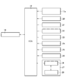
液晶表示器28の表示画面30の略中央には、走行速度が数値で表示される走行速度計31が配置される。表示画面30における走行速度計31の上方には、エンジン18の回転速度が表示される回転速度計32aが配置される。回転速度計32aは、円弧状のメーターを模した図形によって構成される。一方、所定の条件を満たした場合には、表示画面30における走行速度計31の上方に回転速度計32aと切り替わるようにしてエンジン18の負荷率が表示される負荷率計32bが配置される。負荷率計32bは、途中部で屈曲した棒状のメーターを模した図形によって構成される。
表示画面30における左方には、グレンタンク12の穀粒貯留量が表示される穀粒貯留計33が配置される。穀粒貯留計33は、グレンタンク12を模した図形に基準となる単位目盛りが付されて構成される。表示画面30における右方には、燃料残量が表示される燃料残量計34が配置される。燃料残量計34は、穀粒貯留計33と同様にレベルゲージを模した図形に基準となる単位目盛りが付されて構成される。
表示画面30における走行速度計31の下方には、脱穀モニタ35と選別モニタ36とが配置される。脱穀モニタ35は、所定の領域が所定の表示色で表示可能に構成される。選別モニタ36は、所定の領域が所定の表示色で表示可能に構成される。表示画面30における脱穀モニタ35と選別モニタ36との下方には、運転時間、変速装置26の状態および各種警報を数値や文字で表示する情報表示領域37が配置される。
液晶表示器28は、制御装置29に接続され、制御装置29から走行速度、回転速度、負荷率、穀粒貯留量、燃料残量、脱穀部負荷、選別部負荷、運転時間、変速表示、および各種警報に関する信号を取得することが可能である。
制御装置29は、液晶表示器28を制御するものである。制御装置29は、液晶表示器28またはECU19と一体的または別体として構成される。制御装置29は、液晶表示器28を制御するために種々のプログラムが格納される。また、制御装置29は、これらのプログラム等に従って所定の演算を行うことができ、当該演算の結果等を記憶することができる。制御装置29は、実体的には、CPU、ROM、RAM、HDD等がバスで接続される構成であってもよく、あるいはワンチップのLSI等からなる構成であってもよい。
制御装置29は、ECU19に接続され、ECU19からの走行速度、回転速度、負荷率、穀粒貯留量、燃料残量、脱穀部負荷、選別部負荷、運転時間、変速表示、および各種警報に関する信号を取得することが可能である。
制御装置29は、ECU19からの走行速度、回転速度、負荷率、穀粒貯留量、燃料残量、脱穀部負荷、選別部負荷、運転時間、変速表示、および各種警報に関する信号に基づいて液晶表示器28に所定の文字や図形等を表示させることが可能である。また、制御装置29は、液晶表示器28から入力された各種信号を取得することが可能である。すなわち、制御装置29は、コンバイン1についての情報を各種信号に基づいて液晶表示器28に表示し、液晶表示器28からの入力信号をECU19に伝達することが可能である。
次に、図2と図3とを用いて、表示装置27の制御装置29によって液晶表示器28に表示される情報について説明する。
図2に示すように、制御装置29は、ECU19から走行速度、回転速度、負荷率、穀粒貯留量、燃料残量、脱穀部負荷、選別部負荷、運転時間、変速表示、および各種警報に関する信号を取得すると、当該信号に基づいて所定の文字や図形等を液晶表示器28に表示するように信号を伝達する。
具体的には、図3に示すように、液晶表示器28の走行速度計31には、ECU19から取得した走行速度に関する信号に基づいて走行速度が数値により表示される。液晶表示器28の回転速度計32aには、ECU19から取得した回転速度に関する信号に基づいて、対応する目盛り部分を所定の表示色で点灯させることにより回転速度が表示される。回転速度計32aと切り替わるようにして表示される液晶表示器28の負荷率計32bには、ECU19から取得した負荷率に関する信号に基づいて、対応する目盛り部分を所定の表示色で点灯させることにより負荷率が表示される。
液晶表示器28の穀粒貯留計33には、ECU19から取得した穀粒貯留量に関する信号に基づいて、対応する単位目盛り間に所定の表示色の図形を点灯させることにより穀粒貯留量が表示される。液晶表示器28の燃料残量計34には、ECU19から取得した燃料残量に関する信号に基づいて、対応する単位目盛り間に所定の表示色の図形を点灯させることにより燃料残量が表示される。
液晶表示器28の脱穀モニタ35には、ECU19から取得した脱穀部負荷に関する信号に基づいて、対応する領域に所定の表示色の図形を点灯させることにより脱穀部負荷が表示される。液晶表示器28の選別モニタ36には、ECU19から取得した選別部負荷に関する信号に基づいて、対応する領域に所定の表示色の図形を点灯させることにより選別部負荷が表示される。液晶表示器28の情報表示領域37には、ECU19から取得した運転時間、変速装置26の状態および各種警報に関する信号に基づいて、情報表示領域37に数値や文字によって所定の情報が表示される。
以下では、図3を用いて表示装置27の制御装置29による回転速度計32aと負荷率計32bとの切り替えの態様について説明する。本実施形態において、コンバイン1で刈り取り作業を開始する際のエンジン18の負荷率の表示態様について具体的に説明する。なお、本実施形態において、刈り取り作業時における表示態様について説明するがこれに限定されるものではなく、エンジン18に対する負荷の割合を管理すべき作業であればよい。
図3(a)に示すように、制御装置29は、ECU19を介して走行速度、回転速度、穀粒貯留量、燃料残量、脱穀部負荷、選別部負荷、運転時間、変速表示、および各種警報に関する信号を取得する。さらに、制御装置29は、ECU19が回転速度と操作具17のうちアクセル操作具に関する操作量検出センサー17aからの信号とに基づいて、負荷率算出マップから算出したエンジン18の負荷率を取得する。制御装置29は、取得した各信号に基づいて液晶表示器28の走行速度計31、回転速度計32a、穀粒貯留計33、燃料残量計34、脱穀モニタ35、選別モニタ36および情報表示領域37に所定の図形を点灯する。
刈り取りに関する操作具17が操作されると、操作量検出センサー17aからの信号がECU19を介して制御装置29に伝達される(図2参照)。図3(b)に示すように、制御装置29は、操作量検出センサー17aからの信号を取得すると、コンバイン1の刈り取りに関する操作具17が操作されたと判断し、表示画面30に表示されている回転速度計32aを負荷率計32bに切り替えて表示する。制御装置29は、負荷率計32bにECU19から取得した負荷率に関する信号に基づいて、対応する目盛り部分を所定の表示色で点灯させることにより負荷率を表示する。
この際、回転速度計32aと異なる形状からなる負荷率計32bを表示することで、作業者は、回転速度計32aから負荷率計32bに切り替えられたことを容易に認識することが可能である。また、作業者は、コンバイン1の操作に必要な情報を表示画面30から継続して取得しつつ、負荷率計32bからエンジンの負荷率についての情報を取得することが可能である。
制御装置29は、操作量検出センサー17aからの信号により刈り取りに関する操作具17が操作されたと判断している間、負荷率計32bを表示する。制御装置29は、操作量検出センサー17aからの信号が停止して刈り取りに関する操作具17の操作が終了したと判断すると、操作の終了と同時に、もしくは操作の終了から所定時間経過後に負荷率計32bを回転速度計32aに切り替えて表示する。
上述の場合と同様に、制御装置29は、ECU19を介して取得した操作量検出センサー17aからの信号によりコンバイン1の各作業装置に関する操作具17が操作されたと判断すると、表示画面30に表示されている回転速度計32aを負荷率計32bに切り替えて表示する。
以上の如く、本発明に係るエンジン18の負荷率を表示可能なエンジン作業機であるコンバイン1の表示装置27において、エンジン18の回転速度計32aとエンジン18の負荷率計32bとがそれぞれ異なる図形で構成され、コンバイン1の作業状態に基づいて回転速度計32aと負荷率計32bとが択一的に切り替えられて表示されるものである。
このように構成することにより、作業状態を基準として必要な情報であるエンジン18の回転速度または負荷率が所定の図形である回転速度計32aまたは負荷率計32bを用いて表示される。これにより、特定の操作をすることなく作業状態に適したエンジン18の情報を取得することができる。
このように構成することにより、作業状態を基準として必要な情報であるエンジン18の回転速度または負荷率が所定の図形である回転速度計32aまたは負荷率計32bを用いて表示される。これにより、特定の操作をすることなく作業状態に適したエンジン18の情報を取得することができる。
また、所定の操作具17の操作に基づいて回転速度計32aの表示と負荷率計32bとの表示との切り替えが行われるものである。
このように構成することにより、操作具17の操作に連動して表示される情報である回転速度計32aと負荷率計32bとが切り替わる。これにより、特定の操作をすることなく作業状態に適したエンジン18の情報を取得することができる。
このように構成することにより、操作具17の操作に連動して表示される情報である回転速度計32aと負荷率計32bとが切り替わる。これにより、特定の操作をすることなく作業状態に適したエンジン18の情報を取得することができる。
本発明は、エンジン作業機の表示装置の技術に利用することが可能である。
1 コンバイン
18 エンジン
27 表示装置
32a 回転速度計
32b 負荷率計
18 エンジン
27 表示装置
32a 回転速度計
32b 負荷率計
Claims (2)
- エンジンの負荷率を表示可能なエンジン作業機の表示装置において、
エンジンの回転速度計とエンジンの負荷率計とがそれぞれ異なる図形で構成され、エンジン作業機の作業状態に基づいて回転速度計と負荷率計とが択一的に切り替えられて表示されるエンジン作業機の表示装置。 - 所定の操作具の操作に基づいて前記回転速度計の表示と前記負荷率計の表示との切り替えが行われる請求項1に記載のエンジン作業機の表示装置。
Applications Claiming Priority (2)
| Application Number | Priority Date | Filing Date | Title |
|---|---|---|---|
| JP2013-050741 | 2013-03-13 | ||
| JP2013050741A JP2014176314A (ja) | 2013-03-13 | 2013-03-13 | エンジン作業機の表示装置 |
Publications (1)
| Publication Number | Publication Date |
|---|---|
| WO2014141850A1 true WO2014141850A1 (ja) | 2014-09-18 |
Family
ID=51536526
Family Applications (1)
| Application Number | Title | Priority Date | Filing Date |
|---|---|---|---|
| PCT/JP2014/054070 Ceased WO2014141850A1 (ja) | 2013-03-13 | 2014-02-20 | エンジン作業機の表示装置 |
Country Status (2)
| Country | Link |
|---|---|
| JP (1) | JP2014176314A (ja) |
| WO (1) | WO2014141850A1 (ja) |
Families Citing this family (3)
| Publication number | Priority date | Publication date | Assignee | Title |
|---|---|---|---|---|
| KR102566904B1 (ko) * | 2017-06-26 | 2023-08-16 | 가부시끼 가이샤 구보다 | 작업기에 구비되는 표시 장치 |
| JP7233159B2 (ja) * | 2017-06-26 | 2023-03-06 | 株式会社クボタ | 作業機に備えられる表示装置 |
| JP7152337B2 (ja) * | 2019-03-25 | 2022-10-12 | 三菱マヒンドラ農機株式会社 | コンバイン |
Citations (4)
| Publication number | Priority date | Publication date | Assignee | Title |
|---|---|---|---|---|
| JPH11200971A (ja) * | 1998-01-09 | 1999-07-27 | Kubota Corp | 作業車の燃料残量検出装置及び警報装置 |
| JP2003325024A (ja) * | 2002-05-09 | 2003-11-18 | Yanmar Agricult Equip Co Ltd | コンバインにおける制御装置 |
| JP2011063245A (ja) * | 2009-09-19 | 2011-03-31 | Iseki & Co Ltd | 作業車のエンジン負荷表示装置 |
| JP2012194016A (ja) * | 2011-03-16 | 2012-10-11 | Yupiteru Corp | 電子システム及びプログラム |
-
2013
- 2013-03-13 JP JP2013050741A patent/JP2014176314A/ja active Pending
-
2014
- 2014-02-20 WO PCT/JP2014/054070 patent/WO2014141850A1/ja not_active Ceased
Patent Citations (4)
| Publication number | Priority date | Publication date | Assignee | Title |
|---|---|---|---|---|
| JPH11200971A (ja) * | 1998-01-09 | 1999-07-27 | Kubota Corp | 作業車の燃料残量検出装置及び警報装置 |
| JP2003325024A (ja) * | 2002-05-09 | 2003-11-18 | Yanmar Agricult Equip Co Ltd | コンバインにおける制御装置 |
| JP2011063245A (ja) * | 2009-09-19 | 2011-03-31 | Iseki & Co Ltd | 作業車のエンジン負荷表示装置 |
| JP2012194016A (ja) * | 2011-03-16 | 2012-10-11 | Yupiteru Corp | 電子システム及びプログラム |
Also Published As
| Publication number | Publication date |
|---|---|
| JP2014176314A (ja) | 2014-09-25 |
Similar Documents
| Publication | Publication Date | Title |
|---|---|---|
| JP6073714B2 (ja) | 作業機の表示装置 | |
| JP6029509B2 (ja) | コンバイン | |
| EP3146830B1 (en) | Display of subsystem power consumption on an agricultural machine | |
| JP2014176314A (ja) | エンジン作業機の表示装置 | |
| JP2020028224A (ja) | 圃場マップ作成システム | |
| JP2017018014A (ja) | コンバイン | |
| WO2018092719A1 (ja) | 収量分布算出装置及び収量分布算出方法 | |
| JP2019170192A (ja) | コンバイン | |
| JP7034732B2 (ja) | 作業機に備えられる表示装置及び該表示装置が備えられたコンバイン | |
| CN109109664B (zh) | 显示装置 | |
| WO2014141848A1 (ja) | 作業機の表示装置 | |
| JP2009254280A (ja) | コンバインのモニタ表示装置 | |
| JP2015096044A (ja) | 作業機の表示装置 | |
| JP2014176313A (ja) | 作業機の表示装置 | |
| JP4714456B2 (ja) | コンバイン | |
| JP2019170277A (ja) | コンバイン | |
| JP2014218170A (ja) | エンジン作業機の表示装置 | |
| JP2017100465A (ja) | 作業車両 | |
| JP2019004802A (ja) | 作業機に備えられる表示装置及び該表示装置が備えられたコンバイン | |
| JP2019004800A (ja) | 作業機に備えられる表示装置 | |
| JP2005080550A (ja) | 作業機における制御装置 | |
| JP6300573B2 (ja) | 作業車 | |
| JPH1148802A (ja) | 作業車の警報装置 | |
| JP2861049B2 (ja) | コンバイン操縦席の操縦監視装置 | |
| JP2911702B2 (ja) | コンバインの表示装置 |
Legal Events
| Date | Code | Title | Description |
|---|---|---|---|
| 121 | Ep: the epo has been informed by wipo that ep was designated in this application |
Ref document number: 14763953 Country of ref document: EP Kind code of ref document: A1 |
|
| NENP | Non-entry into the national phase |
Ref country code: DE |
|
| 122 | Ep: pct application non-entry in european phase |
Ref document number: 14763953 Country of ref document: EP Kind code of ref document: A1 |