WO2014141786A1 - 冷蔵庫 - Google Patents
冷蔵庫 Download PDFInfo
- Publication number
- WO2014141786A1 WO2014141786A1 PCT/JP2014/052842 JP2014052842W WO2014141786A1 WO 2014141786 A1 WO2014141786 A1 WO 2014141786A1 JP 2014052842 W JP2014052842 W JP 2014052842W WO 2014141786 A1 WO2014141786 A1 WO 2014141786A1
- Authority
- WO
- WIPO (PCT)
- Prior art keywords
- storage container
- cold air
- unit
- storage case
- storage
- Prior art date
- Legal status (The legal status is an assumption and is not a legal conclusion. Google has not performed a legal analysis and makes no representation as to the accuracy of the status listed.)
- Ceased
Links
Images






Classifications
-
- F—MECHANICAL ENGINEERING; LIGHTING; HEATING; WEAPONS; BLASTING
- F25—REFRIGERATION OR COOLING; COMBINED HEATING AND REFRIGERATION SYSTEMS; HEAT PUMP SYSTEMS; MANUFACTURE OR STORAGE OF ICE; LIQUEFACTION SOLIDIFICATION OF GASES
- F25D—REFRIGERATORS; COLD ROOMS; ICE-BOXES; COOLING OR FREEZING APPARATUS NOT OTHERWISE PROVIDED FOR
- F25D17/00—Arrangements for circulating cooling fluids; Arrangements for circulating gas, e.g. air, within refrigerated spaces
- F25D17/04—Arrangements for circulating cooling fluids; Arrangements for circulating gas, e.g. air, within refrigerated spaces for circulating air, e.g. by convection
- F25D17/06—Arrangements for circulating cooling fluids; Arrangements for circulating gas, e.g. air, within refrigerated spaces for circulating air, e.g. by convection by forced circulation
- F25D17/08—Arrangements for circulating cooling fluids; Arrangements for circulating gas, e.g. air, within refrigerated spaces for circulating air, e.g. by convection by forced circulation using ducts
-
- F—MECHANICAL ENGINEERING; LIGHTING; HEATING; WEAPONS; BLASTING
- F25—REFRIGERATION OR COOLING; COMBINED HEATING AND REFRIGERATION SYSTEMS; HEAT PUMP SYSTEMS; MANUFACTURE OR STORAGE OF ICE; LIQUEFACTION SOLIDIFICATION OF GASES
- F25D—REFRIGERATORS; COLD ROOMS; ICE-BOXES; COOLING OR FREEZING APPARATUS NOT OTHERWISE PROVIDED FOR
- F25D17/00—Arrangements for circulating cooling fluids; Arrangements for circulating gas, e.g. air, within refrigerated spaces
- F25D17/04—Arrangements for circulating cooling fluids; Arrangements for circulating gas, e.g. air, within refrigerated spaces for circulating air, e.g. by convection
- F25D17/042—Air treating means within refrigerated spaces
-
- F—MECHANICAL ENGINEERING; LIGHTING; HEATING; WEAPONS; BLASTING
- F25—REFRIGERATION OR COOLING; COMBINED HEATING AND REFRIGERATION SYSTEMS; HEAT PUMP SYSTEMS; MANUFACTURE OR STORAGE OF ICE; LIQUEFACTION SOLIDIFICATION OF GASES
- F25D—REFRIGERATORS; COLD ROOMS; ICE-BOXES; COOLING OR FREEZING APPARATUS NOT OTHERWISE PROVIDED FOR
- F25D25/00—Charging, supporting, and discharging the articles to be cooled
- F25D25/02—Charging, supporting, and discharging the articles to be cooled by shelves
- F25D25/024—Slidable shelves
- F25D25/025—Drawers
-
- F—MECHANICAL ENGINEERING; LIGHTING; HEATING; WEAPONS; BLASTING
- F25—REFRIGERATION OR COOLING; COMBINED HEATING AND REFRIGERATION SYSTEMS; HEAT PUMP SYSTEMS; MANUFACTURE OR STORAGE OF ICE; LIQUEFACTION SOLIDIFICATION OF GASES
- F25D—REFRIGERATORS; COLD ROOMS; ICE-BOXES; COOLING OR FREEZING APPARATUS NOT OTHERWISE PROVIDED FOR
- F25D2317/00—Details or arrangements for circulating cooling fluids; Details or arrangements for circulating gas, e.g. air, within refrigerated spaces, not provided for in other groups of this subclass
- F25D2317/06—Details or arrangements for circulating cooling fluids; Details or arrangements for circulating gas, e.g. air, within refrigerated spaces, not provided for in other groups of this subclass with forced air circulation
- F25D2317/061—Details or arrangements for circulating cooling fluids; Details or arrangements for circulating gas, e.g. air, within refrigerated spaces, not provided for in other groups of this subclass with forced air circulation through special compartments
Definitions
- the present invention relates to a refrigerator provided with a mist generating device that sprays mist-like moisture into a storage chamber.
- Refrigerators with a freezer room, a refrigerator room, and a vegetable room are widely used.
- recent refrigerators are provided with a refrigerator room for storing stored items in a refrigerator, and a vegetable room that is maintained at a higher temperature than the refrigerator compartment and is suitable for storing vegetables.
- a mist generating device is disposed in the vegetable compartment, and the mist generated by the mist generating device is sprayed into the vegetable compartment, whereby the vegetable compartment is humidified and the freshness of vegetables, fruits, and the like is maintained.
- the following is disclosed as the structure of such a refrigerator.
- FIG. 14 is a schematic side sectional view of the vegetable compartment 102 shown in Patent Document 1.
- the refrigerator 101 includes a vegetable room 102 and a refrigerator room 103.
- the vegetable compartment 102 is formed to be slightly hotter and higher in humidity than the refrigerator compartment 103.
- a vegetable container 105 for storing vegetables is disposed so as to be able to be pulled out.
- the vegetable container 105 is detachably attached to the vegetable compartment door 104 and is configured to move integrally with the vegetable compartment door 104.
- a metal plate cover 106 that covers the upper opening of the vegetable container 105 is provided in the upper part of the vegetable compartment 102.
- the cover 106 is configured to cover the top opening of the vegetable container 105 when the vegetable compartment door 104 is closing the opening of the vegetable compartment 102. And since the outer surface of the vegetable container 105 and the cover 106 is cooled by the circulating cold air, dew condensation occurs on the inner surface of the metal cover 106.
- the upper surface wall portion of the cover 106 has a concave portion protruding downward as a whole, and inclined surface portions 106b and 106c are formed so as to be continuous with the deepest portion 106a of the concave portion.
- a mist generating device 107 is disposed on the lower surface of the deepest portion 106 a of the cover 106.
- the mist generator 107 has a water storage tank 108 and an ultrasonic transducer 109.
- Water that has condensed on the inclined surface portions 106b and 106c is introduced into the water storage tank 108.
- a water supply core is provided so as to penetrate the center of the bottom of the water storage tank 108, and the water supply core is held so as to contact the ultrasonic vibrator 109 through a spring.
- the ultrasonic vibrator 109 generates mist-like water fine particles having a particle diameter of, for example, about 5 ⁇ m on the smooth surface by increasing the vibration frequency, and the generated mist-like water fine particles are supplied into the vegetable container 105. Is done.
- This invention is made
- the objective provides the refrigerator which can obtain the water
- the refrigerator according to the present invention is a refrigerator including a storage room in which stored items are refrigerated and stored.
- the storage room includes an inlet into which cold air flows, an outlet from which cold air flows out, a storage case having an opening, and a storage case A lid for forming a storage container that is a closed space together with the storage case, and a mist generator, the storage container having a hole, the mist generator being attached to the hole, and a cooling unit
- the cooling unit is higher in thermal conductivity than the storage container, and is cooled by the cold air that is exposed outside the storage container and flows in from the inlet, and the condensation unit is transmitted from the cooling unit.
- the moisture in the air in the storage container is condensed by cold heat, and the spraying part sprays the moisture condensed in the condensation part into the storage container.
- the cooling section includes a heat radiating section and a heat transfer section, the heat radiating section is cooled by cold air flowing from the inlet, and the heat transfer section condenses the cold heat from the heat radiating section. May be communicated to.
- a heat insulating member may be disposed between the cooling unit and the storage container.
- the cool air flowing in from the inflow port passes through the cool air passage provided on the outer periphery of the storage container, cools the storage container from the outside, and then flows out from the outflow port. It may be arranged at a position closer to the inlet than the outlet.
- the storage container has an opening and a damper that opens and closes the opening. Even if the damper is opened during the mist spraying of the mist generating device, the air in the storage container is caused to flow by cold air. good.
- the refrigerator according to the present invention can obtain a sufficient amount of moisture for spraying in a mist form without impairing an effective space for storing vegetables and the like.
- FIG. 10 is a schematic side view of a vegetable room with the storage case of the fifth embodiment pulled out.
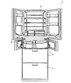
- FIG. 1 is a schematic front view of a refrigerator 1 used in the present embodiment.
- a refrigerator compartment 2 is provided in which stored items are stored in a refrigerator.
- the refrigerator compartment 2 has a tank room for storing a water tank for ice making, an accessory storage room for storing small storage items such as eggs, a chilled room, and the like.
- the chilled room is maintained at a lower temperature than the other areas of the refrigerator room 2.
- the ice making room 5 supplies water from a water tank provided in the refrigerator compartment 2 to make ice and store ice.
- the freezer compartment 3 has an upper chamber and a lower chamber, and preserves the stored items in a frozen state. Note that the upper chamber of the freezing chamber 3 and the ice making chamber 5 are arranged side by side.
- a vegetable compartment 4 is provided below the freezer compartment 3. The vegetable room 4 is maintained at a temperature suitable for refrigerated storage of vegetables and fruits at a higher temperature than the refrigerator room 2.
- a cooler (not shown) is disposed in a cold air duct (not shown) behind the freezer room 3 and the ice making room 5, and is connected to a compressor (not shown) to exchange heat with the air in the cold air duct.
- the cold air flows through the cold air duct and then flows into the refrigerator compartment 2.
- gas which flows out out of the refrigerator compartment 2 flows in into the vegetable compartment 4 via the 1st connection channel
- path 8 (refer FIG. 2).
- the vegetable compartment 4 is hotter than the refrigerator compartment 2.
- the inside of the refrigerator compartment 2 is cooled to 3 ° C., and the inside of the vegetable compartment 4 is cooled to 5 ° C. Operation control of this series of refrigeration cycles is performed by a control unit (not shown).
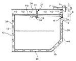
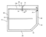
- FIG. 2 is a schematic front cross-sectional view of the vegetable compartment 4 on the line where a mist generating device 21 described later is present.
- FIG. 3 is a schematic side cross-sectional view of the vegetable compartment 4 in the line portion where the mist generating device 21 exists.
- FIGS. 2 and 3 what is present on the cross section is indicated by a solid line, and what is not present on the cross section is indicated by a dotted line.
- the vegetable room 4 has an inlet 6 and an outlet 7.
- the cold air flowing in from the inflow port 6 is cold air that has circulated from the refrigerating chamber 2 via the first connection passage 8.
- the cold air circulates in the vegetable compartment 4 and then flows out from the outlet 7 and is returned to the cooler via the second connection passage 9.
- the partition plate 15 between the inflow port 6 and the outflow port 7 the cold air flowing in from the inflow port 6 flows out from the outflow port 7 after circulating in the vegetable compartment 4. It has become.
- a storage case 10 made of resin is installed in the vegetable compartment 4.
- the storage case 10 has an opening on the upper surface thereof, but is covered with a lid 11 made of resin to create a sealed space.
- the lid 11 covers the opening of the storage case 10, even if air in the storage case 10 tries to escape to the outside, the storage container has a sealed structure. Is forming. Therefore, the cool air circulating in the vegetable compartment 4 is a sealed space by indirect cooling through the storage case 10 and the lid 11 instead of cooling the storage case 10 by directly flowing into the storage case 10. The inside of the storage case 10 is cooled.
- the storage case 10 is connected to a door 13 shown in FIG. 3 by a fixing part 12 shown in FIG. And the storage case 10 is taken in and out of the vegetable compartment 4 according to opening and closing of the door 13 provided in the front surface of the vegetable compartment 4.
- the lid 11 has a hole 14, and a mist generating device 21 is installed so as to penetrate the hole 14.
- the mist generator 21 includes a cooling unit 22, a dew condensation unit 23, and a spray unit 24.
- the cooling unit 22 is exposed from the upper surface of the lid 11.
- the cool air flowing in from the inflow port 6 is radiated and dissipated to transmit the cold heat to the dew condensation unit 23. That is, the cooling unit 22 is directly cooled by cold air.
- the cooling unit 22 uses a material having a higher thermal conductivity than the lid 11, such as copper or aluminum, and can reliably transmit cold heat to the dew condensation unit 23.
- the lid 11 is made of resin and has a lower thermal conductivity than the cooling unit 22. Therefore, since the lid 11 is difficult to transfer heat, the temperature difference between the cooling unit 22 and the inside of the storage case 10 can be maintained.
- the dew condensation part 23 is connected to the cooling part 22 and is provided in a sealed space constituted by the storage case 10 and the lid 11. Since the dew condensation part 23 is cooled to substantially the same temperature as the cooling part 22, the dew condensation part 23 has a temperature lower than the temperature inside the storage case 10. For this reason, moisture in the air in the storage case 10 in contact with the surface of the dew condensation part 23 can be cooled and condensed.
- the dew condensation part 23 is preferably made of a material having a high thermal conductivity like the cooling part 22.
- the spray unit 24 sprays the moisture condensed in the dew condensation unit 23 into the storage case 10. Thereby, moisture reduction, such as vegetables stored in storage case 10, can be controlled, and humidity can be maintained and preservation nature can be improved.
- Various atomizing means such as ultrasonic atomizing means and electrostatic atomizing means can be used for the spraying part 24.
- the ultrasonic atomizing means vibrates and sprays moisture condensed at the dew condensation part 23 by ultrasonic waves.
- the electrostatic atomization means is a method of spraying moisture condensed in the dew condensation unit 23 using electrostatic force by arranging an electrode around the dew condensation unit 23 and applying a high voltage between the electrode and the dew condensation unit 23. It is something to be made.
- the condensed water may be electrolyzed and sprayed with electrolyzed water containing ions. Then, sterilization and washing in the storage case 10 can be performed.
- electrolyzed water since an electrolyzed water can be produced
- the mist generating device 21 since the mist generating device 21 is installed on the lid 11, the water sprayed by the dew condensation unit 23 on the spray unit 24 falls on the stored item in the storage case 10.
- the cold air flowing into the vegetable compartment 4 from the inlet 6 through the first connection passage 8 from the refrigerator compartment 2 passes through the first cold air passage 29 provided on the outer periphery of the storage case 10 according to the arrow. Then, it passes through the second cold air passage 30 provided on the upper side of the lid 11 according to the arrow, and flows out from the outlet 7 to the cooler via the second connection passage 9 outside the vegetable compartment 4.
- the temperature in the storage case 10 becomes higher than the temperature of the cold air circulating in the vegetable compartment 4.
- the cooling unit 22 of the mist generating device 21 is directly cooled by the cold air circulating outside the storage case 10. Cold heat from the cooling unit 22 is transmitted to the dew condensation unit 23. And the temperature of the dew condensation part 23 is lowered than the temperature of the sealed space to induce dew condensation, and the moisture condensed in the dew condensation part 23 is sprayed into the storage case 10 by the spraying part 24, thereby storing in the storage case 10. Things can be maintained at high humidity.
- the temperature of the cold air in the vegetable compartment 4 is 3 to 5 ° C. Even if the cooling unit 22 is cooled at this temperature, the temperature of the surface of the dew condensation part 23 does not become 0 ° C. or less, so that the dew condensation on the surface of the dew condensation part 23 does not freeze. That is, it is possible to generate condensation at a temperature that does not freeze, without performing precise control such as keeping the temperature so as not to freeze while lowering the temperature of the condensation unit 23 to a temperature that causes condensation.
- the inside of the storage case 10 that is indirectly cooled with the cold air in the vegetable compartment 4 has a humidity of 80% or more in a sealed space, and the temperature in the storage case 10 is 3.5 ° C. than the temperature of the dew condensation part 23. If it is higher than this, condensation can be generated.
- the temperature in the storage case 10 is about 8 to 10 ° C., there is a sufficient temperature difference against the occurrence of condensation.
- the temperature in the storage case 10 decreases and the difference from the temperature of the dew condensation portion 23 becomes small, such as when the door 13 is not opened for a long period of time, the temperature in the storage case 10 is too low.
- the temperature of the vegetable compartment 4 including the inside of the storage case 10 rises by detecting that the temperature is detected by a temperature sensor or the like and stopping the cool air flowing from the inlet 6.
- a temperature sensor or the like that the temperature in the storage case 10 is equal to or higher than a predetermined temperature, cold air is again introduced into the vegetable compartment 4 from the inlet 6.
- the inside of the storage case 10 is a sealed space and is not directly cooled by the cold air, while the cooling unit 22 of the mist generating device 21 is directly cooled by the cold air circulating outside the storage case 10. For this reason, the cooling unit 22 is cooled earlier than in the storage case 10. Therefore, since the temperature of the dew condensation part 23 is cooled earlier than the temperature in the storage case 10, a temperature difference necessary for the dew condensation part 23 to condense can be generated.
- the mist generating device 21 exposes the cooling unit 22 from the upper surface of the lid 11 and is disposed in the second cold air passage 30, the cooling unit 22 does not impair the effective space of the storage case 10. Absent. Moreover, since the moisture condensed in the dew condensation part 23 connected to the cooling part 22 is sprayed in the storage case 10 using the spray part 24, the water storage tank for storing dew condensation is unnecessary. For this reason, the effective space of the storage case 10 is not impaired.
- the storage case 10 constitutes a sealed space together with the lid 11, but it does not have to be a complete sealed space, and may be a closed space that can maintain the humidity inside the storage case 10.
- a fan for sending an air flow in parallel with the cold air flow direction may be provided. By doing so, it is possible to achieve both reduction of flow resistance and improvement of heat exchange efficiency.
- mist generating apparatus 2 is applied to the vegetable compartment 4, it is not necessary to limit to it, You may apply to storage rooms other than the vegetable compartment 4, for example, the chilled room which wants to maintain high humidity. .
- lid 11 and the storage case 10 do not have to be limited to being formed of resin, and may have any thermal conductivity lower than that of the cooling unit 22.
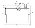
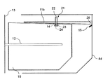
- FIG. 4 is a schematic front sectional view of the vegetable compartment 4a on the line where the mist generating device 21a exists.
- the present embodiment is the same as the first embodiment except that the cooling unit 22a of the mist generating device 21a is composed of a heat radiating unit 25 and a heat transfer unit 26.
- the heat dissipating part 25 is exposed from the upper surface of the lid 11, and cool air flowing in from the inlet 6 hits and dissipates heat.
- the heat transfer part 26 is connected to the heat dissipation part 25 and is provided through the hole 14 of the lid 11 in order to transmit cold heat from the heat dissipation part 25 to the dew condensation part 23.
- the heat-transfer part 26 uses the material with high heat conductivity, such as copper and aluminum.
- the thermal radiation part 25 is provided in the upper surface of the lid
- FIG. 5 is a schematic front cross-sectional view of the vegetable compartment 4b on the line where the mist generating device 21 exists.
- This embodiment is the same as the first embodiment except for the configuration of the lid 11a.
- the lid 11a has a double structure. For example, a hollow portion is formed between two resin plates. Thereby, since heat conduction between the outer surface of the lid 11a through which the cold air flows and the inner surface of the lid 11a in contact with the air in the storage case 10 can be suppressed, the cooling unit 22 and the storage case 10 can be compared with the first embodiment. The temperature difference can be effectively maintained.
- the hollow portion is evacuated or a material having a lower thermal conductivity than that of the resin constituting the lid 11a is inserted, it is more difficult to transfer heat, so the temperature difference between the cooling portion 22 and the storage case 10 Can be maintained more effectively.
- the constituent member of the lid 11a does not have to be limited to being formed of a resin, and any member having a lower thermal conductivity than the cooling unit 22 may be used. Even in this case, the hollow portion of the lid 11a may be evacuated, or a material having a lower thermal conductivity than the member outside the lid 11a may be inserted.
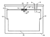
- FIG. 6 is a schematic front cross-sectional view of the vegetable compartment 4c on the line where the mist generating device 21 exists.
- the present embodiment is the same as the first embodiment except that a heat insulating member 27 is disposed between the cooling unit 22 and the lid 11.
- FIG. 7 is a schematic side cross-sectional view of the vegetable compartment 4d on the line where the mist generating device 21 exists.
- FIG. 8 is a schematic side view of the vegetable compartment 4d.
- FIG. 9 is a schematic side view of the vegetable compartment 4d with the storage case 10 pulled out.
- a solid line indicates a portion that is visible from the side surface direction
- a dotted line indicates a portion that is not visible from the side surface direction.
- the upper surface of the storage case 10 is inclined downward from the door 13 side toward the back side, and the lid 11b is shaped to match the storage case 10.
- cover 11b to the vegetable compartment 4d is provided. The rest is the same as the first embodiment.
- the lid 11b is fixed to the vegetable compartment 4d.
- the mist generating device 21 is attached to the lid 11b, since the mist generating device 21 is always present inside the vegetable compartment 4d, failure due to direct touch by the user and improvement of aesthetics are achieved. Can contribute.
- the lid 11 b has a portion that overlaps with the storage case 10 inclining downward from the door 13 side toward the back side in the same manner as the storage case 10.
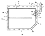
- FIG. 10 is a schematic side cross-sectional view of the vegetable compartment 4e on the line where the mist generating device 31 exists.
- the storage case 10 a has the hole 35 without providing the hole 11 (see FIG. 2) in the lid 11.
- a mist generating device 31 is installed in the hole 35, and the mist generating device 31 includes a cooling unit 32, a dew condensation unit 33, and a spray unit 34.
- Other points are the same as in the first embodiment.
- the cooling unit 32 is closer to the inflow port 6 than the outflow port 7 as compared with the case where the mist generating device is installed in the lid 11. Placed in position. Therefore, the cooling unit 32 of the mist generating device 31 can be directly cooled before the temperature of the inflowing cool air rises by cooling the storage case 10a. Therefore, it is possible to induce condensation in the condensation unit 33 more reliably than in the first embodiment.
- a heat insulating member having a lower thermal conductivity than the resin forming the storage case 10 may be disposed between the cooling unit 32 and the storage case 10. Thereby, the temperature difference in the cooling unit 32 and the storage case 10 can be more effectively maintained.
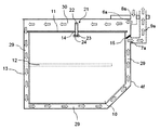
- FIG. 11 is a schematic front cross-sectional view of the vegetable room 4f on the line where the mist generating device 21 exists.
- FIG. 12 is a schematic cross-sectional side view of the vegetable compartment 4f on the line where the mist generating device 21 is present.
- the present embodiment is the same as the first embodiment except that the cold air circulation direction is reversed compared to the first embodiment.
- the cold air flowing from the inflow port 6a through the first connection passage 8a from the refrigerating chamber 2 is provided on the upper side of the lid 11. 2 After passing through the cold air passage 30 according to the arrow, it passes through the first cold air passage 29 provided on the outer periphery of the storage case 10 according to the arrow, and passes from the outlet 7a to the cooler via the second connection passage 9a outside the vegetable compartment 4f. leak.
- the cooling unit 22 flows. It arrange
- FIG. 13 is a schematic side cross-sectional view of the vegetable compartment 4g on the line where the mist generating device 21 exists.
- the lid 11 c has an opening 36, and a damper 37 that opens and closes the opening 36 is provided. Further, during the mist spraying of the mist generating device 21, the damper 37 is opened, and the air in the storage case 10 is caused to flow by the cold air flowing through the second cold air passage 30. Other points are the same as in the first embodiment.
- mist Since mist is heavier than air, it tends to concentrate below the spraying part 24. Therefore, during the mist spraying, the air in the storage case 10 can be moved by introducing cold air from the opening 36, and the mist can be distributed in the storage case 10. During the period when the mist is not sprayed, the damper 37 is closed to prevent the cool air from directly entering the storage case 10, so that the stored items in the storage case 10 can be prevented from drying. Further, a temperature difference between the inside and the outside of the storage case 10 can be generated, and moisture necessary for the next mist spraying can be condensed on the dew condensation part 23.
- the opening 36 is not limited to being provided in the lid 11c, and may be provided in the storage case 10. Further, the opening 36 and the damper 37 may be arranged so that cold air from the opening 36 flows in, or may be arranged so that the air in the storage case 10 flows out from the opening 36.
- the present invention can be widely applied to all refrigerators equipped with a mist generating device.
Landscapes
- Engineering & Computer Science (AREA)
- Chemical & Material Sciences (AREA)
- Combustion & Propulsion (AREA)
- Physics & Mathematics (AREA)
- Mechanical Engineering (AREA)
- Thermal Sciences (AREA)
- General Engineering & Computer Science (AREA)
- Cold Air Circulating Systems And Constructional Details In Refrigerators (AREA)
Abstract
Description
第1実施形態に係る冷蔵庫について、図面を参照して説明すれば、以下の通りである。図1は、本実施形態に用いられる冷蔵庫1の概略的な正面図である。冷蔵庫1の上側には、貯蔵物が冷蔵保存される冷蔵室2を備えている。冷蔵室2は、製氷用の水タンクを収納するタンク室、卵等小さい貯蔵物を収納する小物収納室、及びチルド室等を有する。チルド室は冷蔵室2の他の領域よりも低温に維持されている。
次に、第2実施形態に係る冷蔵庫について、図面を参照して説明すれば、以下の通りである。図4は、ミスト発生装置21aが存在する線上部分の野菜室4aの概略的な正面断面図である。本実施形態は、ミスト発生装置21aの冷却部22aが放熱部25及び伝熱部26から構成されている点以外は、第1実施形態と同じである。
次に、第3実施形態に係る冷蔵庫について、図面を参照して説明すれば、以下の通りである。図5は、ミスト発生装置21が存在する線上部分の野菜室4bの概略的な正面断面図である。本実施形態は、蓋11aの構成以外は、第1実施形態と同じである。
次に、第4実施形態に係る冷蔵庫について、図面を参照して説明すれば、以下の通りである。図6は、ミスト発生装置21が存在する線上部分の野菜室4cの概略的な正面断面図である。本実施形態は、冷却部22と蓋11との間に断熱部材27を配置している点以外は、第1実施形態と同じである。
次に、第5実施形態に係る冷蔵庫について、図面を参照して説明すれば、以下の通りである。図7は、ミスト発生装置21が存在する線上部分の野菜室4dの概略的な側面断面図である。また、図8は、野菜室4dの概略的な側面図である。さらに、図9は、収納ケース10を引き出した状態の野菜室4dの概略的な側面図である。尚、図8及び図9では、側面方向から見えるところに存在するものを実線で示しており、側面方向から見えないところに存在するものを点線で示している。
次に、第6実施形態に係る冷蔵庫について、図面を参照して説明すれば、以下の通りである。図10は、ミスト発生装置31が存在する線上部分の野菜室4eの概略的な側面断面図である。本実施形態は、蓋11に孔14(図2参照)を設けずに、収納ケース10aが孔35を有している。また、その孔35にミスト発生装置31が設置されており、ミスト発生装置31は冷却部32、結露部33及び噴霧部34から構成されている。その他の点は、第1実施形態と同じである。
次に、第7実施形態に係る冷蔵庫について、図面を参照して説明すれば、以下の通りである。図11は、ミスト発生装置21が存在する線上部分の野菜室4fの概略的な正面断面図である。また、図12は、ミスト発生装置21が存在する線上部分の野菜室4fの概略的な側面断面図である。本実施形態は、第1実施形態と比べて、冷気の循環方向を逆にした点以外は、第1実施形態1と同じである。
次に、第8実施形態に係る冷蔵庫について、図面を参照して説明すれば、以下の通りである。図13は、ミスト発生装置21が存在する線上部分の野菜室4gの概略的な側面断面図である。本実施形態は、蓋11cが開孔36を有し、開孔36を開閉するダンパ37が設けられている。また、ミスト発生装置21のミスト噴霧中にダンパ37を開けて第2冷気通路30を流れる冷気によって収納ケース10内の空気を流動させている。それ以外の点は、第1実施形態と同じである。
2 冷蔵室
3 冷凍室
4、4a~4g 野菜室
5 製氷室
6、6a 流入口
7、7a 流出口
8、8a 第1連結通路
9、9a 第2連結通路
10、10a 収納ケース
11、11a~11c 蓋
12 固定部
13 扉
14 孔
15 仕切り板
21、21a、31 ミスト発生装置
22、22a、32 冷却部
23、33 結露部
24、34 噴霧部
25 放熱部
26 伝熱部
27 断熱部材
28 固定部
29 第1冷気通路
30 第2冷気通路
35 孔
36 開孔
37 ダンパ
Claims (5)
- 貯蔵物が冷蔵保存される貯蔵室を備えた冷蔵庫において、
前記貯蔵室は、冷気が流入する流入口、冷気が流出する流出口、開口部を有する収納ケース、該収納ケースの開口部に配されて前記収納ケースと共に閉空間である貯蔵容器を形成するための蓋、及びミスト発生装置を含み、
前記貯蔵容器は孔を有し、
前記ミスト発生装置は、前記孔に取り付けられ、冷却部、結露部、噴霧部から構成され、
前記冷却部は、前記貯蔵容器よりも熱伝導率が高く、前記貯蔵容器外に露出して前記流入口から流入する冷気によって冷却され、
前記結露部は、前記冷却部より伝達される冷熱によって前記貯蔵容器内の空気中の水分を結露させ、
前記噴霧部は、前記結露部で結露した水分を前記貯蔵容器内に噴霧することを特徴とする冷蔵庫。 - 前記冷却部は、放熱部及び伝熱部を有し、
前記放熱部は、前記流入口から流入する冷気によって冷却され、
前記伝熱部は、該放熱部からの冷熱を前記結露部へ伝達することを特徴とする請求項1に記載の冷蔵庫。 - 前記冷却部と前記貯蔵容器との間に断熱部材を配置することを特徴とする請求項1又は請求項2に記載の冷蔵庫。
- 前記流入口から流入する冷気は、前記貯蔵容器の外周に設けた冷気通路を通過して前記貯蔵容器を外側から冷却した後に前記流出口から流出され、
前記冷却部は、前記冷気通路における前記流出口よりも前記流入口に近い位置に配置されることを特徴とする請求項1から請求項3のいずれかに記載の冷蔵庫。 - 前記貯蔵容器は、開孔及び該開孔を開閉するダンパを有し、
前記ミスト発生装置のミスト噴霧中に前記ダンパを開けて前記冷気によって前記貯蔵容器内の空気を流動させることを特徴とする請求項1から請求項4のいずれかに記載の冷蔵庫。
Priority Applications (2)
| Application Number | Priority Date | Filing Date | Title |
|---|---|---|---|
| JP2015505324A JP6088041B2 (ja) | 2013-03-14 | 2014-02-07 | 冷蔵庫 |
| CN201480012370.5A CN105026857B (zh) | 2013-03-14 | 2014-02-07 | 冰箱 |
Applications Claiming Priority (2)
| Application Number | Priority Date | Filing Date | Title |
|---|---|---|---|
| JP2013-051398 | 2013-03-14 | ||
| JP2013051398 | 2013-03-14 |
Publications (1)
| Publication Number | Publication Date |
|---|---|
| WO2014141786A1 true WO2014141786A1 (ja) | 2014-09-18 |
Family
ID=51536462
Family Applications (1)
| Application Number | Title | Priority Date | Filing Date |
|---|---|---|---|
| PCT/JP2014/052842 Ceased WO2014141786A1 (ja) | 2013-03-14 | 2014-02-07 | 冷蔵庫 |
Country Status (3)
| Country | Link |
|---|---|
| JP (1) | JP6088041B2 (ja) |
| CN (1) | CN105026857B (ja) |
| WO (1) | WO2014141786A1 (ja) |
Cited By (2)
| Publication number | Priority date | Publication date | Assignee | Title |
|---|---|---|---|---|
| WO2016050437A1 (en) * | 2014-10-02 | 2016-04-07 | Arcelik Anonim Sirketi | A refrigerator comprising a humidity and temperature controlled special compartment |
| WO2018147253A1 (ja) * | 2017-02-09 | 2018-08-16 | パナソニックIpマネジメント株式会社 | 冷蔵庫 |
Citations (3)
| Publication number | Priority date | Publication date | Assignee | Title |
|---|---|---|---|---|
| JP2004125179A (ja) * | 2002-04-03 | 2004-04-22 | Sanyo Electric Co Ltd | 冷蔵庫及び超音波加湿器 |
| JP2011226758A (ja) * | 2010-03-29 | 2011-11-10 | Panasonic Corp | 冷蔵庫 |
| JP2011226760A (ja) * | 2010-03-29 | 2011-11-10 | Panasonic Corp | 冷蔵庫 |
Family Cites Families (7)
| Publication number | Priority date | Publication date | Assignee | Title |
|---|---|---|---|---|
| JP2004061062A (ja) * | 2002-07-31 | 2004-02-26 | Sanyo Electric Co Ltd | 冷蔵庫 |
| DE112008002167B4 (de) * | 2007-04-26 | 2014-02-06 | Panasonic Corporation | Kühlschrank und elektrische Vorrichtung |
| BRPI0818294B1 (pt) * | 2007-10-09 | 2020-01-21 | Panasonic Corp | refrigerador e método de armazenamento no mesmo |
| JP5326285B2 (ja) * | 2008-01-25 | 2013-10-30 | パナソニック株式会社 | 冷蔵庫 |
| WO2010109989A1 (ja) * | 2009-03-27 | 2010-09-30 | 三菱電機株式会社 | 静電霧化装置及び機器及び空気調和機及び冷蔵庫 |
| JP2011069598A (ja) * | 2009-08-31 | 2011-04-07 | Panasonic Corp | 冷蔵庫 |
| CN102753921B (zh) * | 2010-03-29 | 2016-08-03 | 松下知识产权经营株式会社 | 冷藏库 |
-
2014
- 2014-02-07 CN CN201480012370.5A patent/CN105026857B/zh not_active Expired - Fee Related
- 2014-02-07 WO PCT/JP2014/052842 patent/WO2014141786A1/ja not_active Ceased
- 2014-02-07 JP JP2015505324A patent/JP6088041B2/ja active Active
Patent Citations (3)
| Publication number | Priority date | Publication date | Assignee | Title |
|---|---|---|---|---|
| JP2004125179A (ja) * | 2002-04-03 | 2004-04-22 | Sanyo Electric Co Ltd | 冷蔵庫及び超音波加湿器 |
| JP2011226758A (ja) * | 2010-03-29 | 2011-11-10 | Panasonic Corp | 冷蔵庫 |
| JP2011226760A (ja) * | 2010-03-29 | 2011-11-10 | Panasonic Corp | 冷蔵庫 |
Cited By (2)
| Publication number | Priority date | Publication date | Assignee | Title |
|---|---|---|---|---|
| WO2016050437A1 (en) * | 2014-10-02 | 2016-04-07 | Arcelik Anonim Sirketi | A refrigerator comprising a humidity and temperature controlled special compartment |
| WO2018147253A1 (ja) * | 2017-02-09 | 2018-08-16 | パナソニックIpマネジメント株式会社 | 冷蔵庫 |
Also Published As
| Publication number | Publication date |
|---|---|
| CN105026857B (zh) | 2017-08-29 |
| CN105026857A (zh) | 2015-11-04 |
| JPWO2014141786A1 (ja) | 2017-02-16 |
| JP6088041B2 (ja) | 2017-03-01 |
Similar Documents
| Publication | Publication Date | Title |
|---|---|---|
| KR20160097647A (ko) | 냉장고 | |
| CN102317716B (zh) | 冰箱 | |
| KR20090032733A (ko) | 냉장고의 방열 장치 | |
| CN106940111A (zh) | 用于直冷冰箱的干燥室及直冷冰箱 | |
| JP2009174798A (ja) | 冷蔵庫 | |
| JP6088041B2 (ja) | 冷蔵庫 | |
| JP2014048030A (ja) | 冷却庫 | |
| JP5589698B2 (ja) | 冷蔵庫 | |
| CN107816832B (zh) | 冰箱 | |
| US9982932B2 (en) | Refrigeration appliance with an ice container | |
| JP2011069604A (ja) | 冷蔵庫 | |
| JP2008202882A (ja) | 冷却庫 | |
| JP2011021761A (ja) | 冷蔵庫 | |
| US7555907B2 (en) | Refrigerating storage using thermoelectric element | |
| JP2011208834A (ja) | 冷蔵庫 | |
| KR20100085254A (ko) | 냉장고의 폐열회수 시스템 | |
| JP2006214641A (ja) | 冷蔵庫 | |
| JP5487553B2 (ja) | 冷蔵庫 | |
| JP5922541B2 (ja) | 冷却庫 | |
| JP7620682B2 (ja) | 冷蔵庫 | |
| JP3117766U (ja) | 小形冷蔵庫 | |
| JP2014059112A (ja) | 冷却庫 | |
| JP2010054092A (ja) | 冷蔵庫 | |
| JP2015001315A (ja) | 冷蔵庫 | |
| JP2006189209A (ja) | 冷却庫 |
Legal Events
| Date | Code | Title | Description |
|---|---|---|---|
| WWE | Wipo information: entry into national phase |
Ref document number: 201480012370.5 Country of ref document: CN |
|
| 121 | Ep: the epo has been informed by wipo that ep was designated in this application |
Ref document number: 14765041 Country of ref document: EP Kind code of ref document: A1 |
|
| ENP | Entry into the national phase |
Ref document number: 2015505324 Country of ref document: JP Kind code of ref document: A |
|
| WWE | Wipo information: entry into national phase |
Ref document number: IDP00201505656 Country of ref document: ID |
|
| NENP | Non-entry into the national phase |
Ref country code: DE |
|
| 122 | Ep: pct application non-entry in european phase |
Ref document number: 14765041 Country of ref document: EP Kind code of ref document: A1 |