WO2014141572A1 - 走行玩具 - Google Patents
走行玩具 Download PDFInfo
- Publication number
- WO2014141572A1 WO2014141572A1 PCT/JP2013/085342 JP2013085342W WO2014141572A1 WO 2014141572 A1 WO2014141572 A1 WO 2014141572A1 JP 2013085342 W JP2013085342 W JP 2013085342W WO 2014141572 A1 WO2014141572 A1 WO 2014141572A1
- Authority
- WO
- WIPO (PCT)
- Prior art keywords
- traveling toy
- main body
- toy
- traveling
- toy according
- Prior art date
- Legal status (The legal status is an assumption and is not a legal conclusion. Google has not performed a legal analysis and makes no representation as to the accuracy of the status listed.)
- Ceased
Links
Images


Classifications
-
- A—HUMAN NECESSITIES
- A63—SPORTS; GAMES; AMUSEMENTS
- A63H—TOYS, e.g. TOPS, DOLLS, HOOPS OR BUILDING BLOCKS
- A63H11/00—Self-movable toy figures
- A63H11/02—Self-movable toy figures moved by vibrations produced by rotating eccentric weights
-
- A—HUMAN NECESSITIES
- A63—SPORTS; GAMES; AMUSEMENTS
- A63H—TOYS, e.g. TOPS, DOLLS, HOOPS OR BUILDING BLOCKS
- A63H13/00—Toy figures with self-moving parts, with or without movement of the toy as a whole
- A63H13/02—Toy figures with self-moving parts, with or without movement of the toy as a whole imitating natural actions, e.g. catching a mouse by a cat, the kicking of an animal
-
- A—HUMAN NECESSITIES
- A63—SPORTS; GAMES; AMUSEMENTS
- A63H—TOYS, e.g. TOPS, DOLLS, HOOPS OR BUILDING BLOCKS
- A63H29/00—Drive mechanisms for toys in general
- A63H29/22—Electric drives
Definitions
- the present invention relates to a traveling toy that travels by vibration when rotating an eccentric weight.
- Patent Document 1 There is a toy that mimics the movement of the leg that is inclined by the vibration of the main body (for example, Patent Document 1).
- Patent Document 2 a toy having an elastic leg that supports the body body is proposed by providing an eccentric weight on a rotating shaft that is rotated by a spiral spring in the body body to generate vibration.
- the above-described toy that operates by vibration using the eccentric weight imitates the form of various animals, but it has a leg shape, and it may be difficult to make a toy that looks cute. In addition, the operation lacked straightness in the moving direction.
- the toy according to the present invention has a leg portion and a wheel that solve the above-described problems, have a straight traveling property in the toy, and are easy to change using a step or an inclined surface. A traveling toy is provided.
- the traveling toy according to the present invention has a main body portion having a flat bottom surface, a bottom portion having a curved surface at least at a front portion of the bottom surface, and a substantially hemispherical upper cover portion, and a vibration mechanism is provided inside the main body portion. And a projecting member projecting downward from the bottom surface behind the center of the bottom surface, and a soft elastic member is provided at the tip of the projecting member.
- the vibration mechanism includes a motor and an eccentric weight, and the eccentric weight is rotationally driven by the motor.
- the eccentric weight is arranged in a front portion of the main body portion on the center line in the front-rear direction of the main body portion with the left-right direction of the main body portion being the axial direction of the rotation shaft.
- the soft elastic member has a spherical curved surface, and the center of the lower surface of the protruding member protrudes downward.
- the protruding member is made of a resin having a columnar shape or a cylindrical shape. And the said main-body part is the whole covered with the cloth except the said protrusion member, It is characterized by the above-mentioned.
- the present invention has a projecting member that projects downward from the bottom surface behind the center of the flat bottom portion having a curved surface at least in the front portion, the main body portion is supported by supporting the rear of the main body portion by the projecting member.
- a vibration mechanism By tilting forward and vibrating the main body by a vibration mechanism, when the main body slightly jumps from the grounding surface, it is possible to move forward by generating a forward moving force, and a soft elastic member at the tip of the protruding member
- the forward movement can be reliably performed, and the forward movement having stable straightness can be performed by being grounded and supported by the one point support and the front curved surface.
- the vibration mechanism that rotates the eccentric weight by the motor can be easily reduced in size by the small motor and the eccentric weight, and can be easily made into a cute toy as a small traveling toy by combining with a button battery. It becomes possible.
- the rotation axis of the eccentric weight in the left-right direction and placing it in the front part of the main body part on the center line in the front-rear direction, an advancing force forward obliquely is generated in the front part of the main body part, and excellent in straightness It can be set as the running toy which runs by vibration.
- stable grounding can be performed by forming the soft elastic member at the lower end of the protruding member into a shape having a spherical curved surface.
- the projecting member in a columnar or cylindrical resin and having a structure having a soft elastic body at the tip, a step slightly higher than the soft elastic body having a curved surface is provided on the ground surface.
- the traveling toy can be easily guided and moved by being brought into contact with the resin protruding member. Then, by covering the entire main body of the traveling toy with a cloth, various traveling toys having a warm and cute character can be easily obtained.
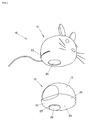
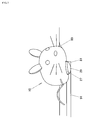
- FIG. 1 is a view showing the appearance of a traveling toy according to the present invention.
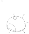
- FIG. 2 is a top perspective view of the main body of the traveling toy according to the present invention.
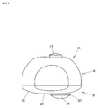
- FIG. 3 is a side view of the main body of the traveling toy according to the present invention.
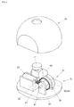
- FIG. 4 is a perspective view showing the internal structure of the traveling toy according to the present invention.
- FIG. 5 is a view showing a state where the traveling toy according to the present invention is placed on a spoon.
- FIG. 6 is a view showing an example of a stage of a traveling toy according to the present invention.
- FIG. 7 is a view showing a state in which the traveling toy according to the present invention is on the step of the stage.
- the embodiment of the traveling toy according to the present invention is configured by a fabric cover 51 and a main body 11, and the main body 11 has a vibration mechanism 31 inside, and a bottom surface 23 of the bottom 21. It has a columnar protruding member 27 and is housed in the fabric cover 51 through an opening 53 of the fabric cover 51 formed of a thick fabric so that the protruding member 27 protrudes from a hole 55 provided in the fabric cover 51. Thus, the whole is covered with the fabric cover 51.
- the main body portion 11 includes an upper cover 15 and a bottom portion 21. As shown in FIGS. 2 and 3, the main body portion 11 has a switch button 17 on the upper surface of the upper cover 15, and the switch button 17 is placed on the fabric cover 51.
- the vibration mechanism 31 operating or operating the vibration mechanism 31 stored in the main body 11 can be stopped by pushing.
- the upper cover 15 and the bottom portion 21 are made of resin, the upper cover 15 has a substantially hemispherical shape with both sides cut off by parallel planes, and the bottom portion 21 has a circular flat plane shape from the periphery of the bottom surface 23 and the bottom surface 23.
- the curved surface 25 has a curved surface 25 that is curved upward, and a part of the curved surface 25 is a plane that is continuous with the cut-off plane of the upper cover 15, and the external shape of the main body 11 is parallel to the cut-off surfaces on both sides.
- the plane is symmetrical with respect to the central plane.
- the bottom portion 21 is formed by integrally molding the bottom portion 21 with a cylindrical projecting member 27 on the center line parallel to the cut-off surfaces on both sides and projecting from the bottom surface 23 at a position removed from the center of the bottom surface 23.
- a soft elastic member 29 is bonded and fixed to the tip of the projecting member 27. And this soft elastic member 29 is made into the shape which made the lower center protruded by the spherical curved surface.
- the direction of the center line parallel to the cut-off surface formed on both sides of the bottom portion 21 is the front-rear direction of the traveling toy 10, the direction in which the protruding member 27 is formed is the rear of the traveling toy 10, and the center line is directed forward.
- the traveling toy 10 includes a battery 49, a motor 33 as the vibration mechanism 31, and an eccentric weight 43.
- the battery 49 uses a button battery to make the traveling toy 10 small. It is possible to make it.
- a pinion 37 is fixed to the motor shaft 35 of the motor 33 serving as the vibration mechanism 31, and a crown gear 39 that meshes with the pinion 37 is fixed to the rotation shaft 41, and the left-right direction orthogonal to the longitudinal center line of the traveling toy 10 Are arranged so as to be in the axial direction of the rotation shaft 41.
- An eccentric weight 43 having a weight 45 removed from the rotation shaft 41 is fixed to the rotation shaft 41, and the eccentric weight 43 is on the center line in the front-rear direction of the traveling toy 10 and ahead of the center position of the traveling toy 10. Is to be placed. Moreover, in this traveling toy 10, the right and left weight balance around the center line in the front-rear direction is achieved so that the left and right weights of the traveling toy 10 are substantially the same depending on the attachment position of the button battery and the attachment position of the motor 33. Yes. Therefore, when the traveling toy 10 covers the main body 11 with the fabric cover 51 and exposes the protruding member 27 from the hole 55 of the fabric cover 51 to be placed on the traveling surface, the front side of the bottom 21 covered with the fabric cover 51 is obtained.
- a forward inclined posture in which the curved surface 25 and the soft elastic member 29 provided at the tip of the protruding member 27 protruding from the fabric cover 51 are brought into contact with the traveling surface can be obtained.
- the vibration mechanism 31 is operated so as to rotate the eccentric weight 43, and the traveling toy 10 vibrates. Due to this vibration, the curved surface 25 of the bottom 21 provided with the fabric cover 51 is repelled from the traveling surface, the soft elastic member 29 is repeatedly compressed and repelled, and the main body 11 of the traveling toy 10 is inclined forward. Thus, a component force is generated due to the vibration forward and obliquely forward, and the traveling traveling forward is started.
- the traveling toy 10 Since the traveling toy 10 is tilted forward with a balance between the left and right weights centered on the center line in the front-rear direction, it is easy to move forward, and the driving force by the eccentric weight 43 travels. Since it is generated in front of the toy 10, a forward force is generated in front of the traveling toy 10 and traveling with stable straightness is performed on a flat ground. Further, by drawing a pattern imitating a rat or a pattern imitating a kitten on the fabric cover 51, a cute appearance and a forward running can be performed. As shown in FIG. It is also possible to move the place of travel on board. As a traveling place of the traveling toy 10, a stage 60 as shown in FIG. 6 may be used.
- the stage 60 includes a house part 71 simulating a house, and a garden part 61 simulating a garden in front of the house part 71, and a roundabout 79 and a bed 77 are provided in the room 73 on the first floor portion of the house part 71.
- a guide step 81 and a guide slope 83 are formed around the hall 75, and a slide 65 is provided.
- the garden portion 61 is provided with a recess 63 imitating a pool and a slope 67 that is an inclined surface that guides the traveling toy 10 into the room 73 of the house portion 71.
- the bed 77 stores the traveling toy 10 as a spoon-shaped or bath-shaped recess, and when the traveling toy 10 is placed in, for example, the hall 75 and the switch button 17 is pushed, the traveling toy 10 is placed in the hall 75. It starts running.
- the traveling toy 10 moves forward along the guiding step 81 by the guiding step 81 and the guiding slope 83 provided around the hall 75, and can slide down from the slide 65 to the garden portion 61.
- the guide step 81 and the guide slope 83 are formed by arranging the step and the slope side by side so that the step and the slope arranged near the step are a fixed distance and the step and the slope are parallel curves or parallel straight lines. It is what. As shown in FIG.
- the step as the guide step 81 is a height that is in contact with the protruding member 27 from the running surface 91 and is lower than the height from the bottom surface 23 of the running toy 10 to the center tip of the soft elastic member 29. That ’s it.
- the guide slope 83 is a slope that curves further upward from the upper end of the guide step 81, and is slightly higher from the running surface 91 than the height from the center tip to the bottom surface 23 of the soft elastic member 29. It is assumed to reach a height, and is inclined and raised from the upper end of the guide step 81 within a range of a distance shorter than the distance from the front surface of the cylindrical projecting member 27 of the traveling toy 10 to the front end of the bottom surface 23. .
- the guide step 81 and the guide slope 83 along the guide step 81 are provided, even if the front end of the traveling toy 10 gets over the guide step 81 by the curved surface 25 formed in front of the bottom surface 23, the guide step 81 is guided. Since the step 81 is at a height in contact with the cylindrical protruding member 27, the protruding member 27 cannot contact the guiding step 81 at the rear of the traveling toy 10, and the protruding member 27 cannot get on the guiding step 81. The traveling toy 10 is prevented from moving forward.
- the front of the traveling toy 10 is lifted by a guide slope 83 formed along the guide step 81, and the front end of the travel toy 10 is guided along the slope of the guide slope 83.
- the direction is changed to the right or left so as to descend along the slope 83, and the front part is placed on the guide step 81 and the protruding member 27 is placed along the guide step 81 along the guide step 81 diagonally forward. Will move. And it can be slid down to the garden part 61 by the slide 65 at the position of the slide 65 where the guide step 81 and the guide slope 83 are cut.
- a stepped portion 89 having a height higher than the thickness of the bottom portion 21 of the traveling toy 10 is formed around the garden portion 61 so that the traveling toy 10 does not fall out of the garden portion 61.
- the garden portion 61 is provided with a recess 63 that imitates a pool.
- the periphery of the recess 63 is provided on the outer periphery of the garden portion 61 so as not to come out of the recess 63.
- a stepped portion 89 having substantially the same height as the stepped portion 89 is formed.
- the slope 67 connecting the garden portion 61 and the house portion 71 is when the traveling toy 10 moves forward as a gentle slope that maintains the forward tilt of the bottom surface 23 without the bottom surface 23 of the traveling toy 10 being horizontal.
- the slope 67 can be climbed to give the pleasure of climbing the slope, and a circuit path 79 is provided in the room 73 in the immediate vicinity of the slope 67.
- the circuit path 79 is formed in a concentric shape with the same step and inclination as the guide step 81 and the guide slope 83 formed in the hall 75 with the guide slope 83 as the outside, and the cutting portion between the guide step 81 and the guide slope 83 is sloped. It is formed to match the upper end of 67.
- the traveling toy 10 climbing the slope 67 enters the inside of the circuit path 79 by the guide step 81 and the guide slope 83 formed in a circular shape from the cut portion of the guide step 81 and the guide slope 83, and the protruding member 27 It abuts on the guide step 81 and moves forward along the migratory path 79 in the clockwise or counterclockwise direction, and comes out of the indoor so as to return to the slope 67 from the cut portion of the migratory path 79.
- the stage 60 prevents the traveling toy 10 from moving forward by the high stepped portion 89 that the traveling toy 10 cannot get over, and the guiding step 81 moves the traveling toy 10 along the step.
- a guide protrusion 85 raised in a hill shape is appropriately disposed on the stage 60, and when the traveling toy 10 gets over the guide protrusion 85 or when the guide protrusion 85 is climbed, the guide protrusion 85 is curved.
- the traveling toy 10 changes the forward direction by the inclined surface.
- a rod-shaped protrusion 87 may be provided as an obstacle to change the direction of travel, and the step of the traveling toy 10 having a straight traveling property, a step or an inclined surface provided on the stage 60 as an auxiliary tool, It is intended to change and enjoy with obstacles.
- the traveling toy 10 is a toy that includes the vibration mechanism 31 inside the main body 11 and has the protruding member 27 behind the bottom surface 23 so that the bottom surface 23 is tilted forward.
- a running toy 10 that is small and does not have a cute leg can be obtained by applying a pattern or an animal appearance on the outer surface.
- this traveling toy 10 moves forward by vibration without having a wheel, it can be operated in accordance with the appearance of the character or animal, has straightness on a flat surface, You can enjoy various games such as driving to The drive mechanism 31 is decelerated using the pinion 37 and the crown gear 39, and the load on the motor 33 is reduced to reduce the load on the battery 49.
- the upper cover 15 of the main body 11 has a substantially hemispherical shape with both sides cut off by parallel planes, and the bottom 21 has a cut-off surface in accordance with the upper cover 15.
- the cover 15 may be a hemispherical elliptical rotating spherical shape, and the bottom 21 may have an elliptical shape matching the upper cover 15, and may be covered with a fabric such as the fabric cover 51.
- the curved surface 25 formed around the bottom surface 23 in the bottom portion 21 is formed at least in front of the bottom surface 23, and the main body portion 11 is provided with a decorative portion on the surface of the upper cover 15 according to the shape of the character or the like. May be formed.
- the traveling toy 10 according to the present invention is a toy that can be easily made into a traveling toy 10 that imitates a cute character or animal without having a leg portion, and has straightness and is suitable. This is a traveling toy 10 that can be enjoyed by performing certain traveling.
Landscapes
- Toys (AREA)
Applications Claiming Priority (2)
| Application Number | Priority Date | Filing Date | Title |
|---|---|---|---|
| JP2013053487A JP6000171B2 (ja) | 2013-03-15 | 2013-03-15 | 走行玩具 |
| JP2013-053487 | 2013-03-15 |
Publications (1)
| Publication Number | Publication Date |
|---|---|
| WO2014141572A1 true WO2014141572A1 (ja) | 2014-09-18 |
Family
ID=51536257
Family Applications (1)
| Application Number | Title | Priority Date | Filing Date |
|---|---|---|---|
| PCT/JP2013/085342 Ceased WO2014141572A1 (ja) | 2013-03-15 | 2013-12-27 | 走行玩具 |
Country Status (2)
| Country | Link |
|---|---|
| JP (1) | JP6000171B2 (enExample) |
| WO (1) | WO2014141572A1 (enExample) |
Families Citing this family (5)
| Publication number | Priority date | Publication date | Assignee | Title |
|---|---|---|---|---|
| JP6827726B2 (ja) * | 2016-07-01 | 2021-02-10 | キヤノン株式会社 | 画像形成装置 |
| JP6517759B2 (ja) * | 2016-08-03 | 2019-05-22 | 株式会社バンダイ | 手動走行玩具 |
| JP6913495B2 (ja) * | 2017-04-03 | 2021-08-04 | 株式会社ヤマダ | 演出用振動ユニット |
| JP7466409B2 (ja) * | 2020-09-01 | 2024-04-12 | アルプスアルパイン株式会社 | 可動玩具 |
| JP7787236B1 (ja) * | 2024-06-21 | 2025-12-16 | 株式会社セガフェイブ | 走行玩具 |
Citations (5)
| Publication number | Priority date | Publication date | Assignee | Title |
|---|---|---|---|---|
| US4219957A (en) * | 1978-05-31 | 1980-09-02 | Takao Kakuta | Traveling toy |
| EP0388246A2 (en) * | 1989-02-16 | 1990-09-19 | Dal Ho Park | Movable toy with vibrating element |
| JPH0461599U (enExample) * | 1990-10-03 | 1992-05-27 | ||
| JP3082217U (ja) * | 2001-05-28 | 2001-12-07 | 株式会社丸彰 | 電動振動走行玩具 |
| JP2009125403A (ja) * | 2007-11-27 | 2009-06-11 | Gijinki Kogei:Kk | 振動移動装置 |
-
2013
- 2013-03-15 JP JP2013053487A patent/JP6000171B2/ja active Active
- 2013-12-27 WO PCT/JP2013/085342 patent/WO2014141572A1/ja not_active Ceased
Patent Citations (5)
| Publication number | Priority date | Publication date | Assignee | Title |
|---|---|---|---|---|
| US4219957A (en) * | 1978-05-31 | 1980-09-02 | Takao Kakuta | Traveling toy |
| EP0388246A2 (en) * | 1989-02-16 | 1990-09-19 | Dal Ho Park | Movable toy with vibrating element |
| JPH0461599U (enExample) * | 1990-10-03 | 1992-05-27 | ||
| JP3082217U (ja) * | 2001-05-28 | 2001-12-07 | 株式会社丸彰 | 電動振動走行玩具 |
| JP2009125403A (ja) * | 2007-11-27 | 2009-06-11 | Gijinki Kogei:Kk | 振動移動装置 |
Also Published As
| Publication number | Publication date |
|---|---|
| JP2014176557A (ja) | 2014-09-25 |
| JP6000171B2 (ja) | 2016-09-28 |
Similar Documents
| Publication | Publication Date | Title |
|---|---|---|
| JP6000171B2 (ja) | 走行玩具 | |
| US8858294B2 (en) | Autonomous bobble head toy | |
| US5360362A (en) | Footprint generating toy | |
| EP2484419A1 (en) | A playset | |
| JP2000342860A (ja) | リモコン玩具 | |
| CN102256677A (zh) | 运动装置,尤其是具有振动马达的自身复原玩具机器人 | |
| US5941755A (en) | Toy having jumping action | |
| US5273479A (en) | Moving and dancing doll | |
| JP2009160238A (ja) | 歩行玩具 | |
| CN201482169U (zh) | 一种趣味动物玩具 | |
| JP3195058U (ja) | 歩行玩具 | |
| CN201912766U (zh) | 可调向的震动爬行玩具 | |
| JP2701121B2 (ja) | ロボット玩具 | |
| JP7362046B1 (ja) | 走行玩具及び走行路トレー | |
| JPH08309037A (ja) | 歩行動物玩具 | |
| CN102049141A (zh) | 可调向的震动爬行玩具 | |
| JPS6121107Y2 (enExample) | ||
| JP2005027959A (ja) | 人形玩具 | |
| JP3139826U (ja) | 幼児用押し車 | |
| JP2015213630A (ja) | 4足歩行おもちゃ | |
| JPH0357273Y2 (enExample) | ||
| WO2016038702A1 (ja) | 回転人形玩具 | |
| JP2022026488A (ja) | 歩行玩具 | |
| JPH07289743A (ja) | 歩行動物玩具 | |
| JPH0582487U (ja) | 充電式動作玩具 |
Legal Events
| Date | Code | Title | Description |
|---|---|---|---|
| 121 | Ep: the epo has been informed by wipo that ep was designated in this application |
Ref document number: 13878334 Country of ref document: EP Kind code of ref document: A1 |
|
| NENP | Non-entry into the national phase |
Ref country code: DE |
|
| 122 | Ep: pct application non-entry in european phase |
Ref document number: 13878334 Country of ref document: EP Kind code of ref document: A1 |