WO2014136935A1 - エンジンの制御装置及び制御方法 - Google Patents
エンジンの制御装置及び制御方法 Download PDFInfo
- Publication number
- WO2014136935A1 WO2014136935A1 PCT/JP2014/055948 JP2014055948W WO2014136935A1 WO 2014136935 A1 WO2014136935 A1 WO 2014136935A1 JP 2014055948 W JP2014055948 W JP 2014055948W WO 2014136935 A1 WO2014136935 A1 WO 2014136935A1
- Authority
- WO
- WIPO (PCT)
- Prior art keywords
- fuel
- compression ratio
- injection
- fuel injection
- injection device
- Prior art date
- Legal status (The legal status is an assumption and is not a legal conclusion. Google has not performed a legal analysis and makes no representation as to the accuracy of the status listed.)
- Ceased
Links
Images

Classifications
-
- F—MECHANICAL ENGINEERING; LIGHTING; HEATING; WEAPONS; BLASTING
- F02—COMBUSTION ENGINES; HOT-GAS OR COMBUSTION-PRODUCT ENGINE PLANTS
- F02D—CONTROLLING COMBUSTION ENGINES
- F02D15/00—Varying compression ratio
- F02D15/02—Varying compression ratio by alteration or displacement of piston stroke
-
- F—MECHANICAL ENGINEERING; LIGHTING; HEATING; WEAPONS; BLASTING
- F02—COMBUSTION ENGINES; HOT-GAS OR COMBUSTION-PRODUCT ENGINE PLANTS
- F02B—INTERNAL-COMBUSTION PISTON ENGINES; COMBUSTION ENGINES IN GENERAL
- F02B17/00—Engines characterised by means for effecting stratification of charge in cylinders
- F02B17/005—Engines characterised by means for effecting stratification of charge in cylinders having direct injection in the combustion chamber
-
- F—MECHANICAL ENGINEERING; LIGHTING; HEATING; WEAPONS; BLASTING
- F02—COMBUSTION ENGINES; HOT-GAS OR COMBUSTION-PRODUCT ENGINE PLANTS
- F02D—CONTROLLING COMBUSTION ENGINES
- F02D1/00—Controlling fuel-injection pumps, e.g. of high pressure injection type
- F02D1/16—Adjustment of injection timing
-
- F—MECHANICAL ENGINEERING; LIGHTING; HEATING; WEAPONS; BLASTING
- F02—COMBUSTION ENGINES; HOT-GAS OR COMBUSTION-PRODUCT ENGINE PLANTS
- F02D—CONTROLLING COMBUSTION ENGINES
- F02D37/00—Non-electrical conjoint control of two or more functions of engines, not otherwise provided for
-
- F—MECHANICAL ENGINEERING; LIGHTING; HEATING; WEAPONS; BLASTING
- F02—COMBUSTION ENGINES; HOT-GAS OR COMBUSTION-PRODUCT ENGINE PLANTS
- F02D—CONTROLLING COMBUSTION ENGINES
- F02D41/00—Electrical control of supply of combustible mixture or its constituents
- F02D41/02—Circuit arrangements for generating control signals
- F02D41/04—Introducing corrections for particular operating conditions
- F02D41/047—Taking into account fuel evaporation or wall wetting
-
- F—MECHANICAL ENGINEERING; LIGHTING; HEATING; WEAPONS; BLASTING
- F02—COMBUSTION ENGINES; HOT-GAS OR COMBUSTION-PRODUCT ENGINE PLANTS
- F02D—CONTROLLING COMBUSTION ENGINES
- F02D41/00—Electrical control of supply of combustible mixture or its constituents
- F02D41/30—Controlling fuel injection
- F02D41/32—Controlling fuel injection of the low pressure type
- F02D41/34—Controlling fuel injection of the low pressure type with means for controlling injection timing or duration
- F02D41/345—Controlling injection timing
-
- F—MECHANICAL ENGINEERING; LIGHTING; HEATING; WEAPONS; BLASTING
- F02—COMBUSTION ENGINES; HOT-GAS OR COMBUSTION-PRODUCT ENGINE PLANTS
- F02D—CONTROLLING COMBUSTION ENGINES
- F02D41/00—Electrical control of supply of combustible mixture or its constituents
- F02D41/30—Controlling fuel injection
- F02D41/38—Controlling fuel injection of the high pressure type
- F02D41/40—Controlling fuel injection of the high pressure type with means for controlling injection timing or duration
- F02D41/401—Controlling injection timing
-
- F—MECHANICAL ENGINEERING; LIGHTING; HEATING; WEAPONS; BLASTING
- F02—COMBUSTION ENGINES; HOT-GAS OR COMBUSTION-PRODUCT ENGINE PLANTS
- F02D—CONTROLLING COMBUSTION ENGINES
- F02D41/00—Electrical control of supply of combustible mixture or its constituents
- F02D41/30—Controlling fuel injection
- F02D41/38—Controlling fuel injection of the high pressure type
- F02D41/40—Controlling fuel injection of the high pressure type with means for controlling injection timing or duration
- F02D41/402—Multiple injections
-
- F—MECHANICAL ENGINEERING; LIGHTING; HEATING; WEAPONS; BLASTING
- F02—COMBUSTION ENGINES; HOT-GAS OR COMBUSTION-PRODUCT ENGINE PLANTS
- F02M—SUPPLYING COMBUSTION ENGINES IN GENERAL WITH COMBUSTIBLE MIXTURES OR CONSTITUENTS THEREOF
- F02M57/00—Fuel-injectors combined or associated with other devices
- F02M57/005—Fuel-injectors combined or associated with other devices the devices being sensors
-
- F—MECHANICAL ENGINEERING; LIGHTING; HEATING; WEAPONS; BLASTING
- F02—COMBUSTION ENGINES; HOT-GAS OR COMBUSTION-PRODUCT ENGINE PLANTS
- F02M—SUPPLYING COMBUSTION ENGINES IN GENERAL WITH COMBUSTIBLE MIXTURES OR CONSTITUENTS THEREOF
- F02M61/00—Fuel-injectors not provided for in groups F02M39/00 - F02M57/00 or F02M67/00
- F02M61/14—Arrangements of injectors with respect to engines; Mounting of injectors
-
- Y—GENERAL TAGGING OF NEW TECHNOLOGICAL DEVELOPMENTS; GENERAL TAGGING OF CROSS-SECTIONAL TECHNOLOGIES SPANNING OVER SEVERAL SECTIONS OF THE IPC; TECHNICAL SUBJECTS COVERED BY FORMER USPC CROSS-REFERENCE ART COLLECTIONS [XRACs] AND DIGESTS
- Y02—TECHNOLOGIES OR APPLICATIONS FOR MITIGATION OR ADAPTATION AGAINST CLIMATE CHANGE
- Y02T—CLIMATE CHANGE MITIGATION TECHNOLOGIES RELATED TO TRANSPORTATION
- Y02T10/00—Road transport of goods or passengers
- Y02T10/10—Internal combustion engine [ICE] based vehicles
- Y02T10/40—Engine management systems
Definitions
- the present invention relates to an engine control device and a control method including a variable compression ratio mechanism for changing the top dead center position of a piston and a fuel injection device for directly injecting fuel into a cylinder.
- Patent Document 1 in a direct injection type internal combustion engine equipped with a variable compression ratio mechanism, when the actual compression ratio is higher than the target compression ratio, fuel injection in which intake stroke injection and compression stroke injection are combined. And delaying the injection start timing of the compression stroke injection in accordance with a decrease in the compression ratio.
- PM emission in an engine equipped with a fuel injection device that directly injects fuel into a cylinder varies depending on fuel adhesion to the piston crown. Further, in an engine provided with a variable compression ratio mechanism that changes the top dead center position of the piston, the distance between the piston and the fuel injection device varies according to the compression ratio. For this reason, in the state of the high compression ratio in which the distance between the piston and the fuel injection device becomes short, the fuel tends to adhere to the piston crown surface, and the PM emission amount may increase.
- the present invention has been made in view of the above problems, and in an engine including a variable compression ratio mechanism and a fuel injection device that directly injects fuel into a cylinder, a control device that can suppress fuel adhesion to the piston crown surface, and An object is to provide a control method.
- the engine control apparatus includes an injection control unit that changes the injection of the fuel injection device so as to reduce the fuel adhering to the piston crown when the compression ratio is increased by the compression ratio variable mechanism. I did it. Also, the engine control method according to the present invention controls the variable compression ratio mechanism according to the operating conditions, and when the compression ratio increases, the fuel injection device injects the fuel adhering to the piston crown surface. Was changed.
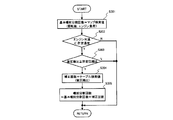
- FIG. 1 is a system diagram of an engine in an embodiment of the present invention. It is a flowchart which shows the flow of control of the injection timing according to the compression ratio in embodiment of this invention. It is a figure which shows the correlation with the injection timing and compression ratio of intake stroke injection in embodiment of this invention, (A) is a time chart which shows the correlation with compression ratio and injection timing, (B) is a crank angle and piston position. FIG. It is a figure which shows the correlation with the injection timing and compression ratio of compression stroke injection in embodiment of this invention, (A) is a time chart which shows the correlation with a compression ratio and injection timing, (B) is a crank angle and piston position. FIG. It is a flowchart which shows the flow of control of the fuel pressure according to the compression ratio in embodiment of this invention. It is a flowchart which shows the flow of control of the division
- FIG. 1 is a diagram illustrating an example of an engine to which a control device and a control method according to the present invention can be applied.
- 1 includes a compression ratio variable mechanism 50 that changes the top dead center position of the piston 33 and a fuel injection device 41 that directly injects fuel into the cylinder.
- the variable compression ratio mechanism 50 connects the crankshaft 32 and the piston 33 with the lower link 11 and the upper link 12 and restricts the movement of the lower link 11 with the control link 13 to change the top dead center position of the piston 33. This is a mechanism for changing the compression ratio.
- the lower link 11 is configured to be split into two left and right members, and is attached to the crankpin 32b of the crankshaft 32 through a substantially central connecting hole. And the lower link 11 rotates centering on the crankpin 32b.
- the crankshaft 32 includes a plurality of journals 32a and a crankpin 32b.
- the journal 32 a is rotatably supported by the cylinder block 31 and the ladder frame 34.
- the crank pin 32b is eccentric by a predetermined amount from the journal 32a, and the lower link 11 is rotatably connected thereto.
- One end of the lower link 11 is connected to the upper link 12 via a connecting pin 21, and the other end of the lower link 11 is connected to the control link 13 via a connecting pin 22.
- the lower end of the upper link 12 is connected to one end of the lower link 11 via the connecting pin 21, and the upper end of the upper link 12 is connected to the piston 33 via the piston pin 23.
- the piston 33 receives the combustion pressure and reciprocates in the cylinder 31 a of the cylinder block 31.
- the control link 13 is rotatably connected to the lower link 11 via a connecting pin 22 provided at the tip, and the other end of the control link 13 is eccentrically connected to the control shaft 25 via a connecting pin 24.
- the control link 13 swings around the connecting pin 24.
- a gear is formed on the control shaft 25, and the gear meshes with a pinion 53 provided on the rotation shaft 52 of the actuator 51. And the control shaft 25 is rotated by the actuator 51, and the connection pin 24 moves.
- the controller 70 as a control device changes the top dead center position of the piston 33 and changes the compression ratio (mechanical compression ratio) of the engine 10 by controlling the actuator 51 and rotating the control shaft 25.
- the fuel injection device (fuel injection valve) 41 is disposed, for example, so as to incline toward the piston 33 side to the side of the combustion chamber so that the spray direction obliquely intersects the axis of the cylinder bore. Inject directly.
- the fuel injection device 41 can be disposed, for example, approximately downward in the center of the ceiling surface of the combustion chamber, and is not limited to the configuration in which the fuel injection device 41 is disposed on the side of the combustion chamber.
- the controller 70 controls fuel injection by the fuel injection device 41 and controls the ignition timing of the spark plug 42.
- the controller 70 includes a microcomputer having a CPU, a ROM, a RAM, an input / output interface, and the like.
- the controller 70 inputs detection signals from various sensors, and the compression ratio variable mechanism 50, the fuel injection device 41, the spark plug 42, and the like.
- the control signal is output.
- the engine 10 includes a load sensor 61 that detects the engine load TP, a rotation sensor 62 that detects the rotational speed NE of the engine 10, a water temperature sensor 63 that detects the temperature TW of the cooling water of the engine 10, and the like. It is provided.
- the temperature of the cooling water of the engine 10 is a temperature that represents the temperature of the engine 10.
- the controller 70 has a function as an injection control unit that changes the injection of the fuel injection device 41 so as to reduce the fuel adhering to the crown surface of the piston 33 when the compression ratio is increased by the compression ratio variable mechanism 50. Yes.
- the amount attached to the crown surface of the piston 33 changes according to the injection timing, the fuel spray penetration, etc., so the function of changing the injection of the fuel injection device 41 described above Includes changing the injection timing and the fuel spray penetration. And by reducing the fuel adhering to the crown surface of the piston 33 when the compression ratio is increased, the PM discharge amount of the engine 10 in the high compression ratio state can be suppressed, and the exhaust property can be improved.
- the flowchart of FIG. 2 shows an example of injection timing control according to the compression ratio, which is performed by the controller 70.
- the controller 70 is a basic injection that is a basic value of timing for starting injection of the fuel injection device 41 in accordance with the operating state of the engine 10 such as the engine load TP and the engine rotational speed NE.
- the starting position is determined by map search or the like.
- the injection timing is set during the intake stroke or the compression stroke, and is expressed by, for example, an advance angle or a retard angle from the reference crank angle position.
- the retard angle direction is indicated by a plus angle
- the advance angle direction is indicated by a minus angle.
- the controller 70 determines whether or not the engine temperature condition is such that the amount of fuel adhering to the piston crown exceeds an allowable level based on the coolant temperature TW.
- the controller 70 can suppress the amount of fuel adhering to the piston crown surface within an allowable level with high atomization performance without changing the injection timing. Estimated.
- the controller 70 allows the amount of fuel adhering to the piston crown surface if the injection timing is not changed in a direction in which the fuel adhering to the piston crown surface decreases. Estimate that the level may be exceeded.
- the predetermined temperature is determined in advance by experiments and simulations so that the estimation process by the controller 70 as described above can be performed.
- the controller 70 determines that it is not necessary to change the injection timing for reducing the fuel adhering to the piston crown surface. Then, the controller 70 controls the injection timing by the fuel injection device 41 based on the basic injection start timing by terminating the present routine as it is.
- step S103 the controller 70 determines whether or not the actual compression ratio changed by the compression ratio variable mechanism 50 is equal to or greater than a predetermined compression ratio. That is, the compression ratio region that is variable by the compression ratio variable mechanism 50 is divided into a high compression ratio region and a low compression ratio region with a predetermined compression ratio as a boundary, and the controller 70 determines that the current actual compression ratio is the high compression ratio region. Or the low compression ratio region.
- the controller 70 can detect the angular position of the control shaft 25 as a state quantity corresponding to the actual compression ratio. That is, the controller 70 can convert the detected value of the angular position of the control shaft 25 into a compression ratio, and can use the compression ratio obtained by the conversion as the actual compression ratio. Also, the detected value of the angular position of the control shaft 25 can be used. And the angular position corresponding to the predetermined compression ratio, it can be determined whether or not the state is a high compression ratio. Since the variable compression ratio mechanism 50 is a mechanism that changes the compression ratio by changing the top dead center position of the piston, the lower the actual compression ratio, the lower the position of the piston at the same crank angle position. The distance between the injection device 41 and the piston crown surface becomes longer. And the longer the distance between the fuel injection device 41 and the piston crown surface, the more difficult the fuel adheres to the piston crown surface.
- the controller 70 determines that the distance between the fuel injection device 41 and the piston crown surface at the injection timing is within an allowable level. It is determined that the length is long enough to be suppressed. And the controller 70 controls the injection timing by the fuel injection device 41 based on the basic injection start timing by ending this routine as it is.
- step S104 the controller 70 determines whether the fuel injection timing by the fuel injection device 41 is set to the intake stroke injection or the compression stroke injection based on the basic injection start timing determined in step S101.
- step S105 the controller 70 sets the first correction angle HA1 based on the actual compression ratio and the basic injection start timing.
- the first correction angle HA1 is a retardation correction term for the basic injection start timing set during the intake stroke. The larger the value of the first correction angle HA1, the larger the basic injection start timing changes to the retard side. Is done.
- the first correction angle HA1 is set to a larger value as the actual compression ratio is higher, and to a larger value as the basic injection start timing is closer to the exhaust top dead center TDC.
- the larger the first correction angle HA1 is set the more the injection timing is retarded.
- the distance between the fuel injection device 41 and the piston crown surface at the injection start timing is equal to or greater than the set value, the amount of fuel adhering to the piston crown surface can be suppressed within an allowable level.
- the fuel injection is performed in a state where the distance between the fuel injection device 41 and the piston crown surface is shorter. Therefore, in order to make the distance between the fuel injection device 41 and the piston crown surface at the injection start timing equal to or greater than the set value, it is necessary to retard the injection timing as the compression ratio increases, that is, away from the exhaust top dead center. is there.
- step S105 the controller 70 sets the first correction angle HA1 to a larger value as the actual compression ratio is higher, and delays the injection start timing more greatly as the actual compression ratio is higher. Further, the controller 70 sets the first correction angle HA1 to a larger value as the basic injection start timing is closer to the exhaust top dead center TDC, and sets the injection start timing as the basic injection start timing is closer to the exhaust top dead center TDC. Delay more greatly.
- step S106 When the controller 70 sets the first correction angle HA1 in step S105, in the next step S106, whether or not the compression ratio obtained by subtracting a predetermined value from the target compression ratio is greater than or equal to the actual compression ratio, in other words, increased. It is determined whether or not it is a transient state in which the actual compression ratio is increasing toward the target compression ratio.
- the actual compression ratio is increasing and changing, even if the first correction angle HA1 is set based on the current actual compression ratio, the change in the fuel injection timing is executed with a delay. At the time of performing, the compression ratio is increased from the time of setting the first correction angle HA1.
- step S106 determines in step S106 that the actual compression ratio is in a transient state
- the controller 70 proceeds to step S107 and sets the second correction angle HA2 according to the changing speed in the increasing direction of the actual compression ratio.
- the controller 70 determines the rate of change in the actual compression ratio in the increasing direction based on the difference between the current actual compression ratio and the previous actual compression ratio.
- the second correction angle HA2 is set to a larger angle as the increase change speed of the actual compression ratio is larger, that is, as the increase margin of the actual compression ratio in the delay time until the actual fuel injection is started is larger. It is set, and the basic injection start timing is delayed more greatly. With this second correction angle HA2, it is possible to compensate for the response delay in the transient state and change the injection timing to match the actual compression ratio.
- step S108 sets the second correction angle HA2 to zero, and cancels the correction by the second correction angle HA2.
- the injection start timing is kept away from the exhaust top dead center, and the amount of fuel adhering to the piston crown is reduced.
- the injection timing is not changed when the compression ratio increases, the distance between the fuel injection device 41 and the crown surface of the piston 33 at the injection timing approaches, and the amount of fuel adhering to the crown surface increases.
- the timing is changed in a direction in which the amount of fuel attached to the piston crown surface decreases.
- the direction in which the amount of fuel adhering to the piston crown surface decreases is the retarded direction in the intake stroke injection.
- step S110 the controller 70 sets the third correction angle HA3 based on the actual compression ratio and the basic injection start timing.
- the third correction angle HA3 is an advance angle correction term for the basic injection start timing set during the compression stroke, and the larger the value of the third correction angle HA3, the larger the basic injection start timing becomes on the advance side. Be changed.
- the third correction angle HA3 is set to a larger value as the actual compression ratio is higher, and to a larger value as the basic injection start timing is closer to the compression top dead center TDC.
- the injection timing is changed to the advance side. As described above, by setting the distance between the fuel injection device 41 and the piston crown surface at the injection start timing to be equal to or greater than the set value, the amount of fuel adhering to the piston crown surface can be suppressed within an allowable level.
- the fuel injection is performed in a state where the distance between the fuel injection device 41 and the piston crown surface is shorter. Therefore, in order to make the distance between the fuel injection device 41 and the piston crown surface at the injection start time equal to or greater than the set value, it is necessary to advance the injection timing as the compression ratio increases, that is, away from the compression top dead center. is there.
- the controller 70 sets the third correction angle HA3 to a larger value as the actual compression ratio is higher, and advances the injection start timing more greatly as the actual compression ratio is higher. Further, the controller 70 sets the third correction angle HA3 to a larger value as the basic injection start timing is closer to the compression top dead center TDC, and sets the injection start timing as the basic injection start timing is closer to the compression top dead center TDC. Advance more.
- the controller 70 determines whether or not the compression ratio obtained by subtracting a predetermined value from the target compression ratio is equal to or greater than the actual compression ratio, in other words, the actual compression ratio increases toward the increased target compression ratio. It is determined whether or not it is in a transient state.
- the actual compression ratio is increasing and changing, even if the third correction angle HA3 is set based on the actual compression ratio at the present time, the change of the fuel injection timing is executed with a delay. At the time of performing, the compression ratio is increased more than when the third correction angle HA3 is set.
- step S111 determines in step S111 that the actual compression ratio is in a transient state where the actual compression ratio is increasing
- the controller 70 proceeds to step S112 and sets the fourth correction angle HA4 according to the changing speed in the increasing direction of the actual compression ratio.
- the fourth correction angle HA4 increases as the increase rate of change in the actual compression ratio increases, that is, the increase in the actual compression ratio during the delay time until the actual fuel injection starts. The larger the margin, the larger the angle is set, and the basic injection start timing is advanced more.
- step S113 sets the fourth correction angle HA4 to zero, and cancels the correction by the fourth correction angle HA4.
- the controller 70 advances the fuel injection start timing when the compression ratio increases, thereby moving the injection start timing away from the compression top dead center, and fuel to the piston crown surface. Reduce the amount of adhesion. That is, if the injection timing is not changed when the compression ratio is increased, the distance between the fuel injection device 41 and the crown surface of the piston 33 at the injection timing approaches, and the amount of fuel adhering to the crown surface increases. The timing is changed in a direction in which the amount of fuel attached to the piston crown surface decreases. The direction in which the amount of fuel adhering to the piston crown surface decreases is the advance direction in the compression stroke injection. Thereby, even if a compression ratio increases, it can suppress that the quantity of the fuel adhering to a piston crown surface increases, and can suppress that PM emission amount of the engine 10 increases.
- the controller 70 can change the injection timing as described above, and also perform the fuel spray penetration of the fuel injection device 41. Can be changed.
- the controller 70 can change the injection timing as described above, and also perform the fuel spray penetration of the fuel injection device 41. Can be changed.
- the compression ratio By increasing the compression ratio, when the fuel spray penetration is weakened when the distance between the fuel injection device 41 and the crown surface of the piston 33 at the injection timing is shortened, the reach of the fuel spray is shortened and the piston crown It is possible to suppress the amount of fuel reaching the surface from decreasing, and thus increase the amount of fuel adhering to the piston crown surface.
- the flowchart in FIG. 5 shows an example of penetration control according to the compression ratio, which is performed by the controller 70.
- the controller 70 changes the fuel spray penetration by changing the pressure FP of the fuel supplied to the fuel injection device 41. That is, if the fuel pressure FP is increased, the penetration increases and the amount of fuel that reaches the piston crown increases and the amount of fuel adhering to the piston crown increases. However, if the fuel pressure FP is decreased, the penetration weakens and the piston increases. The amount of fuel that reaches the crown surface decreases, and the amount of fuel adhering to the piston crown surface decreases.
- the change in the pressure FP of the fuel supplied to the fuel injection device 41 is performed, for example, by controlling a fuel pump included in the fuel supply device 71 that pumps the fuel toward the fuel injection device 41.
- the controller 70 determines the pressure FP of the fuel to be supplied to the fuel injection device 41 in accordance with the operating state of the engine 10 such as the engine load TP, the engine speed NE, and the coolant temperature TW.
- a basic target fuel pressure FPb which is a target value, is determined by a map search or the like.
- step S202 the controller 70 determines whether or not the coolant temperature TW is lower than a predetermined temperature, as in step S102. Then, when the coolant temperature TW is lower than the predetermined temperature and the atomization performance of the fuel injected from the fuel injection device 41 is low, the controller 70 proceeds to step S203.
- step S203 the controller 70 determines whether or not the actual compression ratio changed by the variable compression ratio mechanism 50 is equal to or greater than a predetermined compression ratio, as in step S103. If the actual compression ratio is greater than or equal to the predetermined compression ratio, the controller 70 proceeds to step S204, and sets the fuel pressure correction value HP according to the actual compression ratio and the injection timing of the fuel injection device 41.
- the fuel pressure correction value HP is a correction term that is subtracted from the basic target fuel pressure FPb, and the basic target fuel pressure FPb is corrected to a lower pressure as the fuel pressure correction value HP is larger.
- the fuel pressure correction value HP is set to a larger value as the actual compression ratio is higher, that is, a value for correcting the fuel pressure FP to be lower, and is set to a larger value as the injection timing is closer to the top dead center.
- the fuel pressure correction value HP is set to a larger value as it is closer to the exhaust top dead center
- the compression stroke injection the fuel pressure correction value HP is set to a larger value as it is closer to the compression top dead center. .
- the controller 70 lowers the fuel pressure FP as the compression ratio increases, and weakens the penetration of the fuel spray injected from the fuel injection device 41. Thereby, when the compression ratio is high, the reach of the fuel spray is shortened, and an increase in the amount of fuel adhering to the piston crown surface is suppressed.
- the controller 70 controls the amount of fuel discharged from the fuel supply device 71 so that the actual fuel pressure approaches the target fuel pressure FPtg.
- the fuel pressure FP is changed to a lower value to weaken the penetration, thereby suppressing an increase in the amount of fuel adhering to the crown surface of the piston 33, and the PM of the engine 10 An increase in the amount of discharge can be suppressed.
- the controller 70 performs in parallel the process of moving the injection timing away from the top dead center according to the increase in the compression ratio and the process of changing the fuel pressure FP lower according to the increase in the compression ratio. Can be implemented by switching. As an aspect in which the injection timing control and the fuel pressure control are switched, the controller 70 performs injection when the compression ratio further increases after the injection timing is moved away from the top dead center to the limit angle in accordance with the increase in the compression ratio. It is possible to perform control to reduce the fuel pressure while maintaining the timing. Further, the controller 70 may perform control to keep the fuel injection pressure away from the top dead center when the compression ratio further increases after the fuel pressure is reduced to the limit in accordance with the increase in the compression ratio. it can.
- the fuel spray penetration can be changed by changing the fuel pressure FP, and the penetration can also be changed by changing the number of divisions in divided fuel injection.
- the longer the injection duration the stronger the penetration, so when injecting the same amount of fuel, it is better to divide more times and shorten the injection duration. Becomes weaker.
- the flowchart of FIG. 6 shows an example of the divided injection number control according to the compression ratio, which is performed by the controller 70.
- the controller 70 sets the basic division number DN of the injection by the fuel injection device 41 according to the operating state of the engine 10 such as the engine load TP, the engine speed NE, and the coolant temperature TW. Determined by map search.
- the number of divisions indicates how many times the fuel injection amount per cycle is injected and, for example, when the number of divisions is two, the injection pulse width corresponding to the fuel injection amount is half. After the injection at the time, the injection for the remaining half time is performed after a predetermined interruption period has elapsed.
- the injection amount per time can be non-uniform, and the interruption period can be non-uniform when the number of divisions is three or more.
- step S301 the basic division number DN set in step S301 can be set uniformly to be set so that divided injection is not performed.
- step S302 the controller 70 determines whether or not the coolant temperature TW is lower than a predetermined temperature, as in step S102. When the coolant temperature TW is lower than the predetermined temperature and the atomization (vaporization) performance of the fuel injected from the fuel injection device 41 is low, the controller 70 proceeds to step S303.
- step S303 the controller 70 determines whether or not the actual compression ratio changed by the compression ratio variable mechanism 50 is equal to or greater than a predetermined compression ratio, as in step S103. If the actual compression ratio is greater than or equal to the predetermined compression ratio, the controller 70 proceeds to step S304, and sets the number of corrections HN according to the actual compression ratio.
- the correction number HN is an addition correction term of the basic division number DN.
- the correction number HN is set to a larger value as the actual compression ratio is higher, and the fuel injection is divided into a larger number of times as the actual compression ratio is higher.
- the controller 70 increases the number of divisions DN as the compression ratio increases, shortens the injection time per divided injection, and weakens the penetration of fuel spray injected from the fuel injection device 41. Thereby, the reach distance of the fuel spray is shortened, and an increase in the amount of fuel adhering to the piston crown surface is suppressed.
- the controller 70 divides the control in accordance with the increase in the compression ratio, the control for moving the injection timing away from the top dead center, the control for changing the fuel pressure FP to be lower in accordance with the increase in the compression ratio, and the increase in the compression ratio. At least two of the controls for increasing the number of injection divisions can be performed in parallel or by switching. For example, when the compression ratio further increases after increasing the number of divisions DN to the limit in accordance with an increase in the compression ratio, the controller 70 can perform control to reduce the fuel pressure while maintaining the number of divisions DN. Further, the controller 70 can perform control to increase the number of divisions while maintaining the fuel pressure when the compression ratio further increases after the fuel pressure is reduced to the limit in accordance with the increase in the compression ratio.
- the fuel spray penetration of the fuel injection device 41 can be changed by changing the injection characteristics of the fuel injection device 41 as well as the fuel pressure and the number of divisions.
- the change in the injection characteristics includes both a first fuel injection device that injects a fuel spray with relatively strong penetration and a second fuel injection device that injects a fuel spray with relatively weak penetration. This can be realized by switching the fuel injection device that performs injection. Further, the fuel injection device 41 is provided with a mechanism that can change the penetration, for example, a mechanism that switches the lift position of the valve body, and the penetration can be changed by controlling the mechanism according to the compression ratio. In addition, the correction angle of the injection start timing, the fuel pressure correction value, the number of corrections of divided injection, and the like can be set to larger values as the engine temperature is lower.
Landscapes
- Engineering & Computer Science (AREA)
- Chemical & Material Sciences (AREA)
- Combustion & Propulsion (AREA)
- Mechanical Engineering (AREA)
- General Engineering & Computer Science (AREA)
- Analytical Chemistry (AREA)
- Output Control And Ontrol Of Special Type Engine (AREA)
- Electrical Control Of Air Or Fuel Supplied To Internal-Combustion Engine (AREA)
- Combined Controls Of Internal Combustion Engines (AREA)
Abstract
本発明は、ピストンの上死点位置を変更する圧縮比可変機構と、筒内に燃料を直接噴射する燃料噴射装置とを備えたエンジンの制御装置及び制御方法に関する。本発明に係るエンジンの制御装置及び制御方法では、圧縮比可変機構により圧縮比が増加するときに、ピストン冠面に付着する燃料を減少させるように、燃料噴射装置による燃料噴射における噴射タイミング、燃料圧力、分割噴射回数などを変更する。
Description
本発明は、ピストンの上死点位置を変更する圧縮比可変機構と、筒内に燃料を直接噴射する燃料噴射装置とを備えたエンジンの制御装置及び制御方法に関する。
特許文献1には、圧縮比可変機構を備えた筒内直接噴射式内燃機関において、目標圧縮比に比べて実際の圧縮比が高い場合に、吸気行程噴射と圧縮行程噴射とを組み合わせた燃料噴射を行い、圧縮比の低下に応じて圧縮行程噴射の噴射開始時期を遅角させることが開示されている。
筒内に燃料を直接噴射する燃料噴射装置を備えたエンジンにおけるPM(Particulate Matter)排出量は、ピストン冠面への燃料付着によって変動する。
また、ピストンの上死点位置を変更する圧縮比可変機構を備えたエンジンでは、圧縮比に応じてピストンと燃料噴射装置との距離が変動する。
このため、ピストンと燃料噴射装置との距離が短くなる高圧縮比の状態では、燃料がピストン冠面に付着し易くなり、PM排出量が増加する場合があった。
また、ピストンの上死点位置を変更する圧縮比可変機構を備えたエンジンでは、圧縮比に応じてピストンと燃料噴射装置との距離が変動する。
このため、ピストンと燃料噴射装置との距離が短くなる高圧縮比の状態では、燃料がピストン冠面に付着し易くなり、PM排出量が増加する場合があった。
本発明は上記問題点に鑑みなされたものであり、圧縮比可変機構と筒内に燃料を直接噴射する燃料噴射装置とを備えたエンジンにおいて、ピストン冠面への燃料付着を抑制できる制御装置及び制御方法を提供することを目的とする。
そのため、本発明に係るエンジンの制御装置は、圧縮比可変機構により圧縮比が増加するときに、ピストン冠面に付着する燃料を減少させるように燃料噴射装置の噴射を変更する噴射制御部を備えるようにした。
また、本発明に係るエンジンの制御方法は、運転条件に応じて圧縮比可変機構を制御し、圧縮比が増加するときに、ピストン冠面に付着する燃料を減少させるように燃料噴射装置の噴射を変更するようにした。
また、本発明に係るエンジンの制御方法は、運転条件に応じて圧縮比可変機構を制御し、圧縮比が増加するときに、ピストン冠面に付着する燃料を減少させるように燃料噴射装置の噴射を変更するようにした。
上記発明によると、圧縮比の増加に伴ってピストン冠面に付着する燃料が増えることを抑制でき、以って、エンジンのPM排出量の増大を抑制することができる。
以下に本発明の実施の形態を説明する。
図1は、本発明に係る制御装置及び制御方法を適用可能なエンジンの一例を示す図である。
図1にエンジン10は、ピストン33の上死点位置を変更する圧縮比可変機構50と、筒内に燃料を直接噴射する燃料噴射装置41を備えている。
図1は、本発明に係る制御装置及び制御方法を適用可能なエンジンの一例を示す図である。
図1にエンジン10は、ピストン33の上死点位置を変更する圧縮比可変機構50と、筒内に燃料を直接噴射する燃料噴射装置41を備えている。
圧縮比可変機構50は、クランクシャフト32とピストン33とを、ロアリンク11及びアッパリンク12で連結すると共に、コントロールリンク13でロアリンク11の移動を規制し、ピストン33の上死点位置を変更することで圧縮比を変更する機構である。
ロアリンク11は、左右の2部材に分割可能に構成され、略中央の連結孔でクランクシャフト32のクランクピン32bに取り付けられる。そして、ロアリンク11は、クランクピン32bを中心軸として回転する。
ロアリンク11は、左右の2部材に分割可能に構成され、略中央の連結孔でクランクシャフト32のクランクピン32bに取り付けられる。そして、ロアリンク11は、クランクピン32bを中心軸として回転する。
クランクシャフト32は、複数のジャーナル32aとクランクピン32bとを備える。ジャーナル32aは、シリンダブロック31及びラダーフレーム34によって回転自在に支持される。クランクピン32bは、ジャーナル32aから所定量偏心しており、ここにロアリンク11が回転自在に連結する。
ロアリンク11の一端は、連結ピン21を介してアッパリンク12に連結し、ロアリンク11の他端は、連結ピン22を介してコントロールリンク13に連結する。
ロアリンク11の一端は、連結ピン21を介してアッパリンク12に連結し、ロアリンク11の他端は、連結ピン22を介してコントロールリンク13に連結する。
アッパリンク12の下端は、連結ピン21を介してロアリンク11の一端に連結し、アッパリンク12の上端は、ピストンピン23を介してピストン33に連結する。
ピストン33は、燃焼圧力を受け、シリンダブロック31のシリンダ31a内を往復動する。
ピストン33は、燃焼圧力を受け、シリンダブロック31のシリンダ31a内を往復動する。
コントロールリンク13は、先端に設けた連結ピン22を介して、ロアリンク11に回動可能に連結し、コントロールリンク13の他端は、連結ピン24を介してコントロールシャフト25に偏心して連結し、コントロールリンク13は、連結ピン24を中心として揺動する。
コントロールシャフト25にはギヤが形成されており、ギヤがアクチュエータ51の回転軸52に設けられたピニオン53に噛合する。そして、アクチュエータ51によってコントロールシャフト25が回転させられ、連結ピン24が移動する。
コントロールシャフト25にはギヤが形成されており、ギヤがアクチュエータ51の回転軸52に設けられたピニオン53に噛合する。そして、アクチュエータ51によってコントロールシャフト25が回転させられ、連結ピン24が移動する。
制御装置としてのコントローラ70は、アクチュエータ51を制御してコントロールシャフト25を回転させることで、ピストン33の上死点位置を変更し、エンジン10の圧縮比(機械圧縮比)を変更する。
燃料噴射装置(燃料噴射弁)41は、例えば、噴霧方向がシリダボアの軸心に斜めに交差するように、燃焼室側方にピストン33側を向くように傾けて配置され、筒内に燃料を直接噴射する。
なお、燃料噴射装置41を、例えば燃焼室の天井面の略中央に下向きに配置することができ、燃料噴射装置41を燃焼室側方に配置する構成に限定するものではない。
燃料噴射装置(燃料噴射弁)41は、例えば、噴霧方向がシリダボアの軸心に斜めに交差するように、燃焼室側方にピストン33側を向くように傾けて配置され、筒内に燃料を直接噴射する。
なお、燃料噴射装置41を、例えば燃焼室の天井面の略中央に下向きに配置することができ、燃料噴射装置41を燃焼室側方に配置する構成に限定するものではない。
コントローラ70は、燃料噴射装置41による燃料噴射を制御し、また、点火プラグ42の点火時期を制御する。
コントローラ70は、CPU、ROM、RAM、入出力インタフェースなどを備えたマイクロコンピュータを含んで構成され、各種センサからの検出信号を入力し、圧縮比可変機構50、燃料噴射装置41、点火プラグ42などの制御信号を出力する。
コントローラ70は、CPU、ROM、RAM、入出力インタフェースなどを備えたマイクロコンピュータを含んで構成され、各種センサからの検出信号を入力し、圧縮比可変機構50、燃料噴射装置41、点火プラグ42などの制御信号を出力する。
上記の各種センサとして、エンジン10には、エンジン負荷TPを検出する負荷センサ61、エンジン10の回転速度NEを検出する回転センサ62、エンジン10の冷却水の温度TWを検出する水温センサ63などを設けてある。
なお、エンジン10の冷却水の温度は、エンジン10の温度を代表する温度である。
コントローラ70は、圧縮比可変機構50により圧縮比が増加するときに、ピストン33の冠面に付着する燃料を減少させるように燃料噴射装置41の噴射を変更する噴射制御部としての機能を備えている。
なお、エンジン10の冷却水の温度は、エンジン10の温度を代表する温度である。
コントローラ70は、圧縮比可変機構50により圧縮比が増加するときに、ピストン33の冠面に付着する燃料を減少させるように燃料噴射装置41の噴射を変更する噴射制御部としての機能を備えている。
燃料噴射装置41から噴射された燃料のうち、ピストン33の冠面に付着する量は、噴射タイミング、燃料噴霧のペネトレーションなどに応じて変化するので、上記の燃料噴射装置41の噴射を変更する機能には、噴射タイミング、燃料噴霧のペネトレーションを変更することが含まれる。
そして、圧縮比を増加させるときにピストン33の冠面に付着する燃料を減少させることで、高圧縮比状態でのエンジン10のPM排出量を抑制でき、排気性状を改善することができる。
そして、圧縮比を増加させるときにピストン33の冠面に付着する燃料を減少させることで、高圧縮比状態でのエンジン10のPM排出量を抑制でき、排気性状を改善することができる。
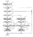
図2のフローチャートは、コントローラ70が実施する、圧縮比に応じた噴射タイミング制御の一例を示す。
図2のフローチャートにおいて、ステップS101で、コントローラ70は、エンジン負荷TP、エンジン回転速度NEなどのエンジン10の運転状態に応じて、燃料噴射装置41の噴射を開始させるタイミングの基本値である基本噴射開始位置を、マップ検索などによって決定する。
図2のフローチャートにおいて、ステップS101で、コントローラ70は、エンジン負荷TP、エンジン回転速度NEなどのエンジン10の運転状態に応じて、燃料噴射装置41の噴射を開始させるタイミングの基本値である基本噴射開始位置を、マップ検索などによって決定する。
噴射タイミングは、吸気行程中又は圧縮行程中に設定され、例えば、基準クランク角度位置から進角角度又は遅角角度で表されるものとする。なお、本願では、遅角方向をプラス角度で示し、進角方向をマイナス角度で示すものとする。
コントローラ70は、ステップS101で基本噴射開始位置を決定すると、次のステップS102で、冷却水温度TWが所定温度よりも低いか否かを判定する。つまり、コントローラ70は、冷却水温度領域を、所定温度を境界として高温領域と低温領域との区分し、ステップS102では、現在の冷却水温が高温領域と低温領域とのいずれに該当しているかを判定する。
コントローラ70は、ステップS101で基本噴射開始位置を決定すると、次のステップS102で、冷却水温度TWが所定温度よりも低いか否かを判定する。つまり、コントローラ70は、冷却水温度領域を、所定温度を境界として高温領域と低温領域との区分し、ステップS102では、現在の冷却水温が高温領域と低温領域とのいずれに該当しているかを判定する。
エンジン10の冷却水温度TWが高い場合には、燃料噴射装置41から噴射される燃料の霧化性能が向上し、噴射タイミングが同じでも冷機に比べてピストン33の冠面に付着する燃料が少なくなる。逆に、冷却水温度TWが低い場合には、高い場合に比べて同じ噴射タイミングでピストン33の冠面に付着する燃料量が多くなる。
そこで、コントローラ70は、ステップS102で、噴射タイミングを変更しないと、ピストン冠面に付着する燃料の量が許容レベルを超える機関温度条件であるか否かを冷却水温度TWに基づき判定する。
そこで、コントローラ70は、ステップS102で、噴射タイミングを変更しないと、ピストン冠面に付着する燃料の量が許容レベルを超える機関温度条件であるか否かを冷却水温度TWに基づき判定する。
つまり、コントローラ70は、所定温度よりも冷却水温度TWが高い場合には、噴射タイミングを変更しなくても、高い霧化性能によって、ピストン冠面に付着する燃料量を許容レベル内に抑制できるものと推定する。また、コントローラ70は、所定温度よりも冷却水温度TWが低い場合には、噴射タイミングをピストン冠面に付着する燃料が減少する方向に変更しないと、ピストン冠面に付着する燃料の量が許容レベルを超える可能性があると推定する。
上記のようなコントローラ70による推定処理が行えるように、所定温度を予め実験やシミュレーションによって決定してある。
従って、コントローラ70は、所定温度よりも冷却水温度TWが高い場合には、ピストン冠面に付着する燃料を低減するための噴射タイミングの変更は不要と判断する。そして、コントローラ70は、そのまま本ルーチンを終了させることで、基本噴射開始時期に基づいて燃料噴射装置41による噴射タイミングを制御する。
上記のようなコントローラ70による推定処理が行えるように、所定温度を予め実験やシミュレーションによって決定してある。
従って、コントローラ70は、所定温度よりも冷却水温度TWが高い場合には、ピストン冠面に付着する燃料を低減するための噴射タイミングの変更は不要と判断する。そして、コントローラ70は、そのまま本ルーチンを終了させることで、基本噴射開始時期に基づいて燃料噴射装置41による噴射タイミングを制御する。
一方、コントローラ70は、所定温度よりも冷却水温度TWが低い場合には、ピストン付着燃料量を低減するために噴射タイミングの変更が必要であると判断して、ステップS103へ進む。
ステップS103で、コントローラ70は、圧縮比可変機構50によって変更される実圧縮比が所定圧縮比以上であるか否かを判定する。即ち、圧縮比可変機構50によって可変とされる圧縮比領域を、所定圧縮比を境に高圧縮比領域と低圧縮比領域に区分し、コントローラ70は、現在の実圧縮比が高圧縮比領域と低圧縮比領域とのいずれに該当しているかを判定する。
ステップS103で、コントローラ70は、圧縮比可変機構50によって変更される実圧縮比が所定圧縮比以上であるか否かを判定する。即ち、圧縮比可変機構50によって可変とされる圧縮比領域を、所定圧縮比を境に高圧縮比領域と低圧縮比領域に区分し、コントローラ70は、現在の実圧縮比が高圧縮比領域と低圧縮比領域とのいずれに該当しているかを判定する。
なお、コントローラ70は、コントロールシャフト25の角度位置を実圧縮比に相当する状態量として検出することができる。つまり、コントローラ70は、コントロールシャフト25の角度位置の検出値を圧縮比に変換し、当該変換で得た圧縮比を実圧縮比として用いることができ、また、コントロールシャフト25の角度位置の検出値と、所定圧縮比に相当する角度位置とを比較することで、高圧縮比状態であるか否かを判定することができる。
圧縮比可変機構50は、ピストンの上死点位置を変更することで圧縮比を変更する機構であるから、実圧縮比が低いほど同じクランク角位置におけるピストンの位置がより低くなり、結果、燃料噴射装置41とピストン冠面との距離がより長くなる。そして、燃料噴射装置41とピストン冠面との距離がより長いなるほど、ピストン冠面に燃料が付着し難くなる。
圧縮比可変機構50は、ピストンの上死点位置を変更することで圧縮比を変更する機構であるから、実圧縮比が低いほど同じクランク角位置におけるピストンの位置がより低くなり、結果、燃料噴射装置41とピストン冠面との距離がより長くなる。そして、燃料噴射装置41とピストン冠面との距離がより長いなるほど、ピストン冠面に燃料が付着し難くなる。
そこで、噴射タイミングを変更しないと、ピストン冠面に付着する燃料の量を許容レベル内に抑えることができない高圧縮比状態を、実圧縮比が所定圧縮比以上の状態として検出することができるように、所定圧縮比を、予め実験やシミュレーションによって決定してある。
従って、コントローラ70は、実圧縮比が所定圧縮比よりも低い場合には、噴射タイミングでの燃料噴射装置41とピストン冠面との距離が、ピストン冠面に付着する燃料の量を許容レベル内に抑えることができる程度に十分に長いと判定する。そして、コントローラ70は、本ルーチンをそのまま終了させることで、基本噴射開始時期に基づいて燃料噴射装置41による噴射タイミングを制御する。
従って、コントローラ70は、実圧縮比が所定圧縮比よりも低い場合には、噴射タイミングでの燃料噴射装置41とピストン冠面との距離が、ピストン冠面に付着する燃料の量を許容レベル内に抑えることができる程度に十分に長いと判定する。そして、コントローラ70は、本ルーチンをそのまま終了させることで、基本噴射開始時期に基づいて燃料噴射装置41による噴射タイミングを制御する。
一方、コントローラ70は、実圧縮比が所定圧縮比以上であれば、噴射タイミングの変更を行わないと、ピストン冠面に付着する燃料の量が許容レベルを超える可能性があると判定し、ステップS104へ進む。
ステップS104で、コントローラ70は、燃料噴射装置41による燃料噴射タイミングが吸気行程噴射と圧縮行程噴射とのいずれに設定されているかを、ステップS101で決定した基本噴射開始時期に基づいて判定する。
ステップS104で、コントローラ70は、燃料噴射装置41による燃料噴射タイミングが吸気行程噴射と圧縮行程噴射とのいずれに設定されているかを、ステップS101で決定した基本噴射開始時期に基づいて判定する。
そして、コントローラ70は、吸気行程中に燃料を噴射させる吸気行程噴射である場合、ステップS105へ進む。
ステップS105で、コントローラ70は、実圧縮比及び基本噴射開始時期に基づき第1補正角度HA1を設定する。
なお、第1補正角度HA1は、吸気行程中に設定される基本噴射開始時期の遅角補正項であり、第1補正角度HA1の値が大きいほど基本噴射開始時期がより大きく遅角側に変更される。
ステップS105で、コントローラ70は、実圧縮比及び基本噴射開始時期に基づき第1補正角度HA1を設定する。
なお、第1補正角度HA1は、吸気行程中に設定される基本噴射開始時期の遅角補正項であり、第1補正角度HA1の値が大きいほど基本噴射開始時期がより大きく遅角側に変更される。
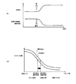
第1補正角度HA1は、図3(A)に示したように、実圧縮比が高いほどより大きな値に設定され、また、基本噴射開始時期が排気上死点TDCに近いほどより大きな値に設定され、第1補正角度HA1が大きいほど噴射タイミングをより遅角させることになる。
ここで、噴射開始時期における燃料噴射装置41とピストン冠面との距離を設定値以上とすることで、ピストン冠面に付着する燃料の量を許容レベル内に抑えることができる。
ここで、噴射開始時期における燃料噴射装置41とピストン冠面との距離を設定値以上とすることで、ピストン冠面に付着する燃料の量を許容レベル内に抑えることができる。
一方、図3(B)に示すように、圧縮比が高いほど同じ噴射時期でのピストン冠面はより高くなり、また、ピストンが下降する吸気行程での噴射では、噴射タイミングが進角するほど、燃料噴射装置41とピストン冠面との距離がより短い状態で燃料噴射を行うことになる。
従って、噴射開始時期における燃料噴射装置41とピストン冠面との距離を設定値以上とするためには、圧縮比が高いほど噴射タイミングをより遅角させる、つまり、排気上死点から遠ざける必要がある。
従って、噴射開始時期における燃料噴射装置41とピストン冠面との距離を設定値以上とするためには、圧縮比が高いほど噴射タイミングをより遅角させる、つまり、排気上死点から遠ざける必要がある。
また、基本噴射開始時期がより遅角側であるほど、噴射開始時期における燃料噴射装置41とピストン冠面との距離を設定値以上とするために要求される噴射タイミングの遅角補正量は小さくなる。
そこで、ステップS105で、コントローラ70は、実圧縮比が高いほど第1補正角度HA1をより大きな値に設定して、実圧縮比が高いほど噴射開始時期をより大きく遅角させる。また、コントローラ70は、基本噴射開始時期が排気上死点TDCに近いほど第1補正角度HA1をより大きな値に設定して、基本噴射開始時期が排気上死点TDCに近いほど噴射開始時期をより大きく遅角させる。
そこで、ステップS105で、コントローラ70は、実圧縮比が高いほど第1補正角度HA1をより大きな値に設定して、実圧縮比が高いほど噴射開始時期をより大きく遅角させる。また、コントローラ70は、基本噴射開始時期が排気上死点TDCに近いほど第1補正角度HA1をより大きな値に設定して、基本噴射開始時期が排気上死点TDCに近いほど噴射開始時期をより大きく遅角させる。
コントローラ70は、ステップS105で第1補正角度HA1を設定すると、次のステップS106では、目標圧縮比から所定値を減算した圧縮比が実圧縮比以上であるか否か、換言すれば、増大した目標圧縮比に向けて実圧縮比が増大しつつある過渡状態であるか否かを判定する。
実圧縮比が増大変化している場合には、現時点での実圧縮比に基づき第1補正角度HA1を設定しても、燃料噴射タイミングの変更は遅れて実行されるから、実際に燃料噴射を行う時点では、第1補正角度HA1を設定した時点よりも圧縮比が増大していることになる。
実圧縮比が増大変化している場合には、現時点での実圧縮比に基づき第1補正角度HA1を設定しても、燃料噴射タイミングの変更は遅れて実行されるから、実際に燃料噴射を行う時点では、第1補正角度HA1を設定した時点よりも圧縮比が増大していることになる。
そこで、コントローラ70は、ステップS106で、実圧縮比が増大しつつある過渡状態であると判定すると、ステップS107へ進み、実圧縮比の増大方向への変化速度に応じて第2補正角度HA2を設定する。
なお、コントローラ70は、実圧縮比の増大方向への変化速度を、今回実圧縮比と前回実圧縮比との差に基づいて判断する。
ここで、第2補正角度HA2は、実圧縮比の増大変化速度が大きいほど、つまり、実際に燃料噴射が開始されるまでの遅れ時間における実圧縮比の増大代が大きいほど、より大きな角度に設定され、基本噴射開始時期をより大きく遅角する。
係る第2補正角度HA2により、過渡状態で応答遅れを補償して、実圧縮比に見合った噴射タイミングに変更することができる。
なお、コントローラ70は、実圧縮比の増大方向への変化速度を、今回実圧縮比と前回実圧縮比との差に基づいて判断する。
ここで、第2補正角度HA2は、実圧縮比の増大変化速度が大きいほど、つまり、実際に燃料噴射が開始されるまでの遅れ時間における実圧縮比の増大代が大きいほど、より大きな角度に設定され、基本噴射開始時期をより大きく遅角する。
係る第2補正角度HA2により、過渡状態で応答遅れを補償して、実圧縮比に見合った噴射タイミングに変更することができる。
一方、実圧縮比が増大しつつある過渡状態でない場合、コントローラ70は、ステップS108へ進み、第2補正角度HA2を零として、第2補正角度HA2による補正をキャンセルする。
ステップS109で、コントローラ70は、燃料噴射開始位置を、基本噴射開始位置から第1補正角度HA1及び第2補正角度HA2だけ遅角した位置に設定する。つまり、コントローラ70は、以下の式に従って燃料噴射開始位置を算出する。
燃料噴射開始位置=基本噴射開始位置+第1補正角度HA1+第2補正角度HA2
そして、コントローラ70は、ステップS109で設定した燃料噴射開始位置が検出されたときに、燃料噴射装置41に向けて噴射パルス信号を出力する。
ステップS109で、コントローラ70は、燃料噴射開始位置を、基本噴射開始位置から第1補正角度HA1及び第2補正角度HA2だけ遅角した位置に設定する。つまり、コントローラ70は、以下の式に従って燃料噴射開始位置を算出する。
燃料噴射開始位置=基本噴射開始位置+第1補正角度HA1+第2補正角度HA2
そして、コントローラ70は、ステップS109で設定した燃料噴射開始位置が検出されたときに、燃料噴射装置41に向けて噴射パルス信号を出力する。
以上のように、吸気行程噴射においては、圧縮比が増加するときに燃料噴射開始時期を遅角させることで、排気上死点から噴射開始時期を遠ざけ、ピストン冠面への燃料付着量を減少させる。
つまり、圧縮比の増加するときに噴射タイミングを変更しないと、噴射タイミングにおける燃料噴射装置41とピストン33の冠面との距離が近づき、冠面に付着する燃料の量が増えてしまうため、噴射タイミングを、ピストン冠面への燃料付着量が減少する方向に変更する。ここで、ピストン冠面への燃料付着量が減少する方向は、吸気行程噴射では遅角方向となる。
これにより、圧縮比が増大しても、ピストン冠面に付着する燃料の量が増えることを抑制でき、以って、エンジン10のPM排出量が増えることを抑制できる。
つまり、圧縮比の増加するときに噴射タイミングを変更しないと、噴射タイミングにおける燃料噴射装置41とピストン33の冠面との距離が近づき、冠面に付着する燃料の量が増えてしまうため、噴射タイミングを、ピストン冠面への燃料付着量が減少する方向に変更する。ここで、ピストン冠面への燃料付着量が減少する方向は、吸気行程噴射では遅角方向となる。
これにより、圧縮比が増大しても、ピストン冠面に付着する燃料の量が増えることを抑制でき、以って、エンジン10のPM排出量が増えることを抑制できる。
また、コントローラ70は、ステップS104で圧縮行程噴射が設定されていると判定すると、ステップS110へ進む。
ステップS110で、コントローラ70は、実圧縮比及び基本噴射開始時期に基づき第3補正角度HA3を設定する。
なお、第3補正角度HA3は、圧縮行程中に設定される基本噴射開始時期の進角補正項であり、第3補正角度HA3の値が大きいほど、基本噴射開始時期がより大きく進角側に変更される。
ステップS110で、コントローラ70は、実圧縮比及び基本噴射開始時期に基づき第3補正角度HA3を設定する。
なお、第3補正角度HA3は、圧縮行程中に設定される基本噴射開始時期の進角補正項であり、第3補正角度HA3の値が大きいほど、基本噴射開始時期がより大きく進角側に変更される。
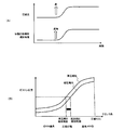
第3補正角度HA3は、図4(A)に示したように、実圧縮比が高いほどより大きな値に設定され、また、基本噴射開始時期が圧縮上死点TDCに近いほどより大きな値に設定され、第3補正角度HA3が大きいほど噴射タイミングはより進角側に変更される。
前述のように、噴射開始時期における燃料噴射装置41とピストン冠面との距離を、設定値以上とすることで、ピストン冠面に付着する燃料の量を許容レベル内に抑えることができる。
前述のように、噴射開始時期における燃料噴射装置41とピストン冠面との距離を、設定値以上とすることで、ピストン冠面に付着する燃料の量を許容レベル内に抑えることができる。
一方、図4(B)に示すように、圧縮比が高いほど同じ噴射時期でのピストン冠面はより高くなり、また、ピストンが上昇する圧縮行程での噴射では、噴射タイミングが遅角するほど、燃料噴射装置41とピストン冠面との距離がより短い状態で燃料噴射を行うことになる。
従って、噴射開始時期における燃料噴射装置41とピストン冠面との距離を設定値以上とするためには、圧縮比が高いほど噴射タイミングをより進角させる、つまり、圧縮上死点から遠ざける必要がある。
従って、噴射開始時期における燃料噴射装置41とピストン冠面との距離を設定値以上とするためには、圧縮比が高いほど噴射タイミングをより進角させる、つまり、圧縮上死点から遠ざける必要がある。
また、基本噴射開始時期がより進角側であるほど、噴射開始時期における燃料噴射装置41とピストン冠面との距離を設定値以上とするために要求される、噴射タイミングの進角補正量は小さくなる。
そこで、コントローラ70は、ステップS110で、第3補正角度HA3を実圧縮比が高いほどより大きな値に設定して、実圧縮比が高いほど噴射開始時期をより大きく進角させる。また、コントローラ70は、基本噴射開始時期が圧縮上死点TDCに近いほど第3補正角度HA3をより大きな値に設定して、基本噴射開始時期が圧縮上死点TDCに近いほど噴射開始時期をより大きく進角させる。
そこで、コントローラ70は、ステップS110で、第3補正角度HA3を実圧縮比が高いほどより大きな値に設定して、実圧縮比が高いほど噴射開始時期をより大きく進角させる。また、コントローラ70は、基本噴射開始時期が圧縮上死点TDCに近いほど第3補正角度HA3をより大きな値に設定して、基本噴射開始時期が圧縮上死点TDCに近いほど噴射開始時期をより大きく進角させる。
次のステップS111で、コントローラ70は、目標圧縮比から所定値を減算した圧縮比が実圧縮比以上であるか否か、換言すれば、増大した目標圧縮比に向けて実圧縮比が増大しつつある過渡状態であるか否かを判定する。
実圧縮比が増大変化している場合には、現時点での実圧縮比に基づき第3補正角度HA3を設定しても、燃料噴射タイミングの変更は遅れて実行されるから、実際に燃料噴射を行う時点では、第3補正角度HA3を設定した時点でよりも圧縮比が増大していることになる。
実圧縮比が増大変化している場合には、現時点での実圧縮比に基づき第3補正角度HA3を設定しても、燃料噴射タイミングの変更は遅れて実行されるから、実際に燃料噴射を行う時点では、第3補正角度HA3を設定した時点でよりも圧縮比が増大していることになる。
そこで、ステップS111で、コントローラ70は、実圧縮比が増大しつつある過渡状態であると判定すると、ステップS112へ進み、実圧縮比の増大方向への変化速度に応じて第4補正角度HA4を設定する。
ここで、第4補正角度HA4は、第2補正角度HA2と同様に、実圧縮比の増大変化速度が大きいほど、つまり、実際に燃料噴射が開始されるまでの遅れ時間における実圧縮比の増大代が大きいほどより大きな角度に設定され、基本噴射開始時期をより大きく進角する。
ここで、第4補正角度HA4は、第2補正角度HA2と同様に、実圧縮比の増大変化速度が大きいほど、つまり、実際に燃料噴射が開始されるまでの遅れ時間における実圧縮比の増大代が大きいほどより大きな角度に設定され、基本噴射開始時期をより大きく進角する。
一方、実圧縮比が増大しつつある過渡状態でない場合、コントローラ70は、ステップS113へ進み、第4補正角度HA4を零として、第4補正角度HA4による補正をキャンセルする。
そして、ステップS114で、コントローラ70は、燃料噴射開始位置を、基本噴射開始位置から第3補正角度HA3及び第4補正角度HA4だけ進角した位置に設定する。つまり、コントローラ70は、以下の式に従って燃料噴射開始時期を算出する。
燃料噴射開始位置=基本噴射開始位置-第3補正角度HA3-第4補正角度HA4
そして、ステップS114で、コントローラ70は、燃料噴射開始位置を、基本噴射開始位置から第3補正角度HA3及び第4補正角度HA4だけ進角した位置に設定する。つまり、コントローラ70は、以下の式に従って燃料噴射開始時期を算出する。
燃料噴射開始位置=基本噴射開始位置-第3補正角度HA3-第4補正角度HA4
以上のように、コントローラ70は、圧縮行程噴射においては、圧縮比が増加するときに燃料噴射開始時期を進角させることで、圧縮上死点から噴射開始時期を遠ざけ、ピストン冠面への燃料付着量を減少させる。
つまり、圧縮比の増加するときに噴射タイミングを変更しないと、噴射タイミングにおける燃料噴射装置41とピストン33の冠面との距離が近づき、冠面に付着する燃料の量が増えてしまうため、噴射タイミングを、ピストン冠面への燃料付着量が減少する方向に変更する。
なお、ピストン冠面への燃料付着量が減少する方向は、圧縮行程噴射では進角方向となる。
これにより、圧縮比が増大しても、ピストン冠面に付着する燃料の量が増えることを抑制でき、以って、エンジン10のPM排出量が増えることを抑制できる。
つまり、圧縮比の増加するときに噴射タイミングを変更しないと、噴射タイミングにおける燃料噴射装置41とピストン33の冠面との距離が近づき、冠面に付着する燃料の量が増えてしまうため、噴射タイミングを、ピストン冠面への燃料付着量が減少する方向に変更する。
なお、ピストン冠面への燃料付着量が減少する方向は、圧縮行程噴射では進角方向となる。
これにより、圧縮比が増大しても、ピストン冠面に付着する燃料の量が増えることを抑制でき、以って、エンジン10のPM排出量が増えることを抑制できる。
ところで、ピストン冠面への燃料付着量を減少させるための燃料噴射装置41の噴射の変更として、コントローラ70は、前述のように噴射タイミングを変更できる他、燃料噴射装置41の燃料噴霧のペネトレーションを変更できる。
圧縮比を高くすることで、噴射タイミングにおける燃料噴射装置41とピストン33の冠面との距離が短くなるときに、燃料噴霧のペネトレーションを弱めれば、燃料噴霧の到達距離が短くなってピストン冠面にまで到達する燃料が減り、以って、ピストン冠面への燃料付着量が増えることを抑制できる。
圧縮比を高くすることで、噴射タイミングにおける燃料噴射装置41とピストン33の冠面との距離が短くなるときに、燃料噴霧のペネトレーションを弱めれば、燃料噴霧の到達距離が短くなってピストン冠面にまで到達する燃料が減り、以って、ピストン冠面への燃料付着量が増えることを抑制できる。
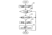
図5のフローチャートは、コントローラ70が実施する、圧縮比に応じたペネトレーション制御の一例を示す。
図5のフローチャートに示す制御で、コントローラ70は、燃料噴射装置41に供給される燃料の圧力FPを変更することで、燃料噴霧のペネトレーションを変更する。
つまり、燃料圧力FPを高くすれば、ペネトレーションが強まってピストン冠面にまで到達する燃料が増え、ピストン冠面への燃料付着量が増えるが、燃料圧力FPを低くすれば、ペネトレーションが弱まってピストン冠面にまで到達する燃料が減り、ピストン冠面への燃料の付着量が減少する。
図5のフローチャートに示す制御で、コントローラ70は、燃料噴射装置41に供給される燃料の圧力FPを変更することで、燃料噴霧のペネトレーションを変更する。
つまり、燃料圧力FPを高くすれば、ペネトレーションが強まってピストン冠面にまで到達する燃料が増え、ピストン冠面への燃料付着量が増えるが、燃料圧力FPを低くすれば、ペネトレーションが弱まってピストン冠面にまで到達する燃料が減り、ピストン冠面への燃料の付着量が減少する。
なお、燃料噴射装置41に供給される燃料の圧力FPの変更は、例えば、燃料噴射装置41に向けて燃料を圧送する燃料供給装置71に含まれる燃料ポンプの制御などによって行われる。
図5のフローチャートにおいて、ステップS201で、コントローラ70は、エンジン負荷TP、エンジン回転速度NE、冷却水温度TWなどのエンジン10の運転状態に応じて、燃料噴射装置41に供給する燃料の圧力FPの目標値である基本目標燃圧FPbを、マップ検索などによって決定する。
図5のフローチャートにおいて、ステップS201で、コントローラ70は、エンジン負荷TP、エンジン回転速度NE、冷却水温度TWなどのエンジン10の運転状態に応じて、燃料噴射装置41に供給する燃料の圧力FPの目標値である基本目標燃圧FPbを、マップ検索などによって決定する。
ステップS202で、コントローラ70は、ステップS102と同様に、冷却水温度TWが所定温度よりも低いか否かを判定する。
そして、コントローラ70は、冷却水温度TWが所定温度よりも低く、燃料噴射装置41から噴射される燃料の霧化性能が低い場合に、ステップS203へ進む。
そして、コントローラ70は、冷却水温度TWが所定温度よりも低く、燃料噴射装置41から噴射される燃料の霧化性能が低い場合に、ステップS203へ進む。
ステップS203で、コントローラ70は、ステップS103と同様に、圧縮比可変機構50によって変更される実圧縮比が所定圧縮比以上であるか否かを判定する。
ここで、実圧縮比が所定圧縮比以上であれば、コントローラ70は、ステップS204へ進み、実圧縮比及び燃料噴射装置41の噴射タイミングに応じて燃圧補正値HPを設定する。
ここで、実圧縮比が所定圧縮比以上であれば、コントローラ70は、ステップS204へ進み、実圧縮比及び燃料噴射装置41の噴射タイミングに応じて燃圧補正値HPを設定する。
なお、燃圧補正値HPは、基本目標燃圧FPbから減算される補正項であり、燃圧補正値HPの値が大きいほど、基本目標燃圧FPbはより低い圧に補正される。
燃圧補正値HPは、実圧縮比が高いほどより大きな値、つまり、燃料圧力FPをより低く補正する値に設定され、また、噴射タイミングが上死点に近いほどより大きな値に設定される。
なお、吸気行程噴射では排気上死点に近いほど燃圧補正値HPはより大きな値に設定され、また、圧縮行程噴射では圧縮上死点に近いほど燃圧補正値HPはより大きな値に設定される。
燃圧補正値HPは、実圧縮比が高いほどより大きな値、つまり、燃料圧力FPをより低く補正する値に設定され、また、噴射タイミングが上死点に近いほどより大きな値に設定される。
なお、吸気行程噴射では排気上死点に近いほど燃圧補正値HPはより大きな値に設定され、また、圧縮行程噴射では圧縮上死点に近いほど燃圧補正値HPはより大きな値に設定される。
前述のように、圧縮比が高いほど同じ噴射タイミングでのピストン冠面はより高くなって、燃料噴射装置41とピストン冠面との距離がより短い状態で燃料噴射を行うことになり、ピストン冠面に燃料が付着し易くなる。
そこで、コントローラ70は、圧縮比が高いほど燃料圧力FPをより低くして、燃料噴射装置41から噴射される燃料噴霧のペネトレーションを弱める。これにより、圧縮比が高いときに燃料噴霧の到達距離が短くなり、ピストン冠面に付着する燃料量が増えることが抑制される。
そこで、コントローラ70は、圧縮比が高いほど燃料圧力FPをより低くして、燃料噴射装置41から噴射される燃料噴霧のペネトレーションを弱める。これにより、圧縮比が高いときに燃料噴霧の到達距離が短くなり、ピストン冠面に付着する燃料量が増えることが抑制される。
また、噴射タイミングが上死点に近いほど、噴射タイミングにおける燃料噴射装置41とピストン冠面との距離が短くなるので、コントローラ70は、噴射タイミングが上死点に近いほど燃料圧力FPをより低くして、燃料噴射装置41から噴射される燃料噴霧のペネトレーションを弱める。これにより、噴射タイミングが上死点に近いときに燃料噴霧の到達距離が短くなり、ピストン冠面に付着する燃料量が増えることが抑制される。
コントローラ70は、ステップS204で燃圧補正値HPを設定すると、ステップS205に進み、燃料噴射装置41に供給する燃料の圧力の最終的な目標値FPtgを、基本目標燃圧FPbから燃圧補正値HPを減算した値に設定する。
つまり、コントローラ70は、以下の式に従って目標値FPtgを算出する。
FPtg=FPb-HP
コントローラ70は、ステップS204で燃圧補正値HPを設定すると、ステップS205に進み、燃料噴射装置41に供給する燃料の圧力の最終的な目標値FPtgを、基本目標燃圧FPbから燃圧補正値HPを減算した値に設定する。
つまり、コントローラ70は、以下の式に従って目標値FPtgを算出する。
FPtg=FPb-HP
そして、コントローラ70は、実際の燃料圧力が目標燃圧FPtgに近づくように、燃料供給装置71からの燃料の吐出量を制御する。
上記のように、圧縮比を増加させるときに、燃料圧力FPをより低く変更してペネトレーションを弱めることで、ピストン33の冠面に付着する燃料の量が増えることを抑制でき、エンジン10のPM排出量が増大することを抑制できる。
上記のように、圧縮比を増加させるときに、燃料圧力FPをより低く変更してペネトレーションを弱めることで、ピストン33の冠面に付着する燃料の量が増えることを抑制でき、エンジン10のPM排出量が増大することを抑制できる。
なお、コントローラ70は、圧縮比の増大に応じて噴射タイミングを上死点から遠ざける処理と、圧縮比の増大に応じて燃料圧力FPをより低く変更する処理とを、並行して実施したり、切り替えて実施したりすることができる。
噴射タイミング制御と燃圧制御とを切り替えて実施する態様として、コントローラ70は、圧縮比の増大に応じて噴射タイミングを上死点から限界角度まで遠ざけた後に、更に圧縮比が増大するときに、噴射タイミングを保持したまま燃圧を低下させる制御を実施することができる。また、コントローラ70は、圧縮比の増大に応じて燃圧を限界まで低下させた後に、更に圧縮比が増大するときに、燃圧を保持したまま噴射タイミングを上死点から遠ざける制御を実施することができる。
噴射タイミング制御と燃圧制御とを切り替えて実施する態様として、コントローラ70は、圧縮比の増大に応じて噴射タイミングを上死点から限界角度まで遠ざけた後に、更に圧縮比が増大するときに、噴射タイミングを保持したまま燃圧を低下させる制御を実施することができる。また、コントローラ70は、圧縮比の増大に応じて燃圧を限界まで低下させた後に、更に圧縮比が増大するときに、燃圧を保持したまま噴射タイミングを上死点から遠ざける制御を実施することができる。
ところで、燃料噴霧のペネトレーションの変更は、燃料圧力FPの変更によって行える他、分割燃料噴射における分割回数を変更することによっても、ペネトレーションを変更することができる。
燃料噴射においては、噴射の継続時間が長くなるほどペネトレーションが強くなるので、同じ量の燃料を噴射する場合に、より多くの回数に分けて噴射を行って噴射の継続時間を短くした方が、ペネトレーションは弱くなる。
燃料噴射においては、噴射の継続時間が長くなるほどペネトレーションが強くなるので、同じ量の燃料を噴射する場合に、より多くの回数に分けて噴射を行って噴射の継続時間を短くした方が、ペネトレーションは弱くなる。
図6のフローチャートは、コントローラ70が実施する、圧縮比に応じた分割噴射回数制御の一例を示す。
図6のフローチャートにおいて、ステップS301で、コントローラ70は、エンジン負荷TP、エンジン回転速度NE、冷却水温度TWなどのエンジン10の運転状態に応じて、燃料噴射装置41による噴射の基本分割回数DNをマップ検索などによって決定する。
図6のフローチャートにおいて、ステップS301で、コントローラ70は、エンジン負荷TP、エンジン回転速度NE、冷却水温度TWなどのエンジン10の運転状態に応じて、燃料噴射装置41による噴射の基本分割回数DNをマップ検索などによって決定する。
なお、分割回数とは、1サイクル当たりの燃料噴射量を何回に分けて噴射させるかを示し、例えば、分割回数を2回とする場合には、燃料噴射量に相当する噴射パルス幅の半分の時間での噴射を行った後、所定の中断期間が経過してから、残る半分の時間での噴射を行わせる。
ただし、各回当たりの噴射量は不均一とすることができ、また、分割回数を3回以上とする場合に、中断期間を不均一とすることができる。
ただし、各回当たりの噴射量は不均一とすることができ、また、分割回数を3回以上とする場合に、中断期間を不均一とすることができる。
また、ステップS301で設定される基本分割回数DNを一律に1回として、分割噴射を行わない設定とすることができる。
ステップS302で、コントローラ70は、ステップS102と同様に、冷却水温度TWが所定温度よりも低いか否かを判定する。
そして、冷却水温度TWが所定温度よりも低く、燃料噴射装置41から噴射される燃料の霧化(気化)性能が低い場合、コントローラ70は、ステップS303へ進む。
ステップS302で、コントローラ70は、ステップS102と同様に、冷却水温度TWが所定温度よりも低いか否かを判定する。
そして、冷却水温度TWが所定温度よりも低く、燃料噴射装置41から噴射される燃料の霧化(気化)性能が低い場合、コントローラ70は、ステップS303へ進む。
ステップS303で、コントローラ70は、ステップS103と同様に、圧縮比可変機構50によって変更される実圧縮比が所定圧縮比以上であるか否かを判定する。
ここで、実圧縮比が所定圧縮比以上であれば、コントローラ70はステップS304へ進み、実圧縮比に応じて補正回数HNを設定する。
ここで、実圧縮比が所定圧縮比以上であれば、コントローラ70はステップS304へ進み、実圧縮比に応じて補正回数HNを設定する。
なお、補正回数HNは、基本分割回数DNの加算補正項であり、補正回数HNの値が大きいほど基本分割回数DNがより多い回数に補正され、より細かく噴射パルス幅が分割されることになる。
補正回数HNは、実圧縮比が高いほどより大きな値に設定され、実圧縮比が高くなるほど燃料噴射をより多くの回数に分割して実施させる。
補正回数HNは、実圧縮比が高いほどより大きな値に設定され、実圧縮比が高くなるほど燃料噴射をより多くの回数に分割して実施させる。
前述のように、圧縮比が高いほど同じ噴射タイミングでのピストン冠面はより高くなって、燃料噴射装置41とピストン冠面との距離がより短い状態で燃料噴射を行うことになり、ピストン冠面に燃料が付着し易くなる。
そこで、コントローラ70は、圧縮比が高いほど分割回数DNを増やして、分割噴射の1回当たりの噴射時間を短くし、燃料噴射装置41から噴射される燃料噴霧のペネトレーションを弱める。これにより、燃料噴霧の到達距離が短くなり、ピストン冠面に付着する燃料量が増えることが抑制される。
そこで、コントローラ70は、圧縮比が高いほど分割回数DNを増やして、分割噴射の1回当たりの噴射時間を短くし、燃料噴射装置41から噴射される燃料噴霧のペネトレーションを弱める。これにより、燃料噴霧の到達距離が短くなり、ピストン冠面に付着する燃料量が増えることが抑制される。
コントローラ70は、ステップS304で補正回数HNを設定すると、ステップS305に進み、燃料噴射装置41の分割噴射における最終的な分割回数DNtgを、基本分割回数DNに補正回数HNを加算した値に設定する。
つまり、コントローラ70は、以下の式に従って最終的な分割回数DNtgを算出する。
DNtg=DN+HN
そして、コントローラ70は、分割回数DNtgに応じて1サイクル当たりの燃料噴射を分割して行わせる。
上記のように、コントローラ70は、圧縮比が増加するときに、分割噴射における分割回数DNを増やして燃料噴霧のペネトレーションを弱めることで、ピストン33の冠面に付着する燃料の量が増えることを抑制し、エンジン10のPM排出量が増大することを抑制する。
つまり、コントローラ70は、以下の式に従って最終的な分割回数DNtgを算出する。
DNtg=DN+HN
そして、コントローラ70は、分割回数DNtgに応じて1サイクル当たりの燃料噴射を分割して行わせる。
上記のように、コントローラ70は、圧縮比が増加するときに、分割噴射における分割回数DNを増やして燃料噴霧のペネトレーションを弱めることで、ピストン33の冠面に付着する燃料の量が増えることを抑制し、エンジン10のPM排出量が増大することを抑制する。
なお、コントローラ70は、圧縮比の増大に応じて噴射タイミングを上死点から遠ざける制御と、圧縮比の増大に応じて燃料圧力FPをより低く変更する制御と、圧縮比の増大に応じて分割噴射の分割回数を増やす制御とのうちの少なくとも2つを、並行で実施したり、切り替えて実施したりすることができる。
コントローラ70は、例えば、圧縮比の増大に応じて分割回数DNを限界まで増やした後に更に圧縮比が増大するときには、分割回数DNを保持したまま燃圧を低下させる制御を実施することができる。また、コントローラ70は、圧縮比の増大に応じて燃圧を限界まで低下させた後に更に圧縮比が増大するときには、燃圧を保持したまま分割回数を増やす制御を実施することができる。
コントローラ70は、例えば、圧縮比の増大に応じて分割回数DNを限界まで増やした後に更に圧縮比が増大するときには、分割回数DNを保持したまま燃圧を低下させる制御を実施することができる。また、コントローラ70は、圧縮比の増大に応じて燃圧を限界まで低下させた後に更に圧縮比が増大するときには、燃圧を保持したまま分割回数を増やす制御を実施することができる。
以上、好ましい実施形態を参照して本発明の内容を具体的に説明したが、本発明の基本的技術思想及び教示に基づいて、当業者であれば、種々の変形態様を採り得ることは自明である。
例えば、燃料噴射装置41の燃料噴霧のペネトレーションの変更は、燃料圧力、分割回数によって変更できる他、燃料噴射装置41における噴射特性を変更することによっても実行可能である。
例えば、燃料噴射装置41の燃料噴霧のペネトレーションの変更は、燃料圧力、分割回数によって変更できる他、燃料噴射装置41における噴射特性を変更することによっても実行可能である。
噴射特性の変更は、ペネトレーションが相対的に強い燃料噴霧を噴射する第1の燃料噴射装置と、ペネトレーションが相対的に弱い燃料噴霧を噴射する第2の燃料噴射装置との双方を備え、実際に噴射を行わせる燃料噴射装置を切り替えることで実現できる。
また、燃料噴射装置41にペネトレーションを変更できる機構、例えば、弁体のリフト位置を切り替える機構などを設け、圧縮比に応じて係る機構を制御することで、ペネトレーションを変更することができる。
また、噴射開始時期の補正角度、燃圧補正値、分割噴射の補正回数などを、機関温度が低いほどより大きな値に設定することができる。
また、燃料噴射装置41にペネトレーションを変更できる機構、例えば、弁体のリフト位置を切り替える機構などを設け、圧縮比に応じて係る機構を制御することで、ペネトレーションを変更することができる。
また、噴射開始時期の補正角度、燃圧補正値、分割噴射の補正回数などを、機関温度が低いほどより大きな値に設定することができる。
10…エンジン、33…ピストン、41…燃料噴射装置、50…圧縮比可変機構、70…コントローラ
Claims (15)
- ピストンの上死点位置を変更する圧縮比可変機構と、筒内に燃料を直接噴射する燃料噴射装置とを備えたエンジンの制御装置であって、
前記制御装置は、前記圧縮比可変機構により圧縮比が増加するときに、ピストン冠面に付着する燃料を減少させるように前記燃料噴射装置の噴射を変更する噴射制御部を備える、エンジンの制御装置。 - 前記噴射制御部は、前記燃料噴射装置による噴射タイミングを変更して前記ピストン冠面に付着する燃料を減少させる、請求項1記載のエンジンの制御装置。
- 前記噴射制御部は、前記燃料噴射装置によって噴射される燃料噴霧のペネトレーションを変更して前記ピストン冠面に付着する燃料を減少させる、請求項1記載のエンジンの制御装置。
- 前記噴射制御部は、前記圧縮比可変機構により圧縮比が増加するときに、前記燃料噴射装置による噴射タイミングを上死点から遠ざかる方向に変更する、請求項1記載のエンジンの制御装置。
- 前記噴射制御部は、前記圧縮比可変機構により圧縮比を増加するときに、前記燃料噴射装置による分割噴射における分割回数を増やす、請求項1記載のエンジンの制御装置。
- 前記噴射制御部は、前記圧縮比可変機構により圧縮比が増加するときに、前記燃料噴射装置の燃料圧力を低下させる、請求項1記載のエンジンの制御装置。
- 前記噴射制御部は、前記圧縮比可変機構により圧縮比が増加するときに、前記燃料噴射装置による噴射タイミングを上死点から遠ざかる方向に変更する処理、前記燃料噴射装置による分割噴射における分割回数を増やす処理、前記燃料噴射装置の燃料圧力を低下させる処理のうちの少なくとも1つを実行する、請求項1記載のエンジンの制御装置。
- 前記噴射制御部は、エンジンの温度が設定温度よりも低い状態において前記圧縮比可変機構により圧縮比が増加するときに、前記ピストンの冠面に付着する燃料を減少させるように前記燃料噴射装置の噴射を変更する、請求項1記載のエンジンの制御装置。
- 前記噴射制御部は、前記圧縮比可変機構により圧縮比が増加するときに、前記ピストン冠面に付着する燃料を、エンジンの温度が低いほどより大きく減少させるように前記燃料噴射装置の噴射を変更する、請求項1記載のエンジンの制御装置。
- 前記燃料噴射装置は、噴射特性が相互に異なる複数の燃料噴射装置を含み、
前記噴射制御部は、燃料噴射を行わせる燃料噴射装置を切り替えて、前記ピストン冠面に付着する燃料を減少させる、請求項1記載のエンジンの制御装置。 - 前記噴射制御部は、前記圧縮比可変機構により圧縮比が増加するときに、圧縮行程における前記燃料噴射装置の噴射タイミングを進角させる、請求項1記載のエンジンの制御装置。
- ピストンの上死点位置を変更する圧縮比可変機構と、筒内に燃料を直接噴射する燃料噴射装置とを備えたエンジンの制御方法であって、
運転条件に応じて前記圧縮比可変機構を制御し、
圧縮比が増加するときに、ピストン冠面に付着する燃料を減少させるように前記燃料噴射装置の噴射を変更する、
エンジンの制御方法。 - 前記燃料噴射装置の噴射を変更するステップは、
圧縮比が増加するときに、前記燃料噴射装置による噴射タイミングを上死点から遠ざかる方向に変更する、請求項12記載のエンジンの制御方法。 - 前記燃料噴射装置の噴射を変更するステップは、
圧縮比が増加するときに、前記燃料噴射装置による分割噴射における分割回数を増やす、請求項12記載のエンジンの制御方法。 - 前記燃料噴射装置の噴射を変更するステップは、
圧縮比が増加するときに、前記燃料噴射装置の燃料圧力を低下させる、請求項12記載のエンジンの制御方法。
Priority Applications (2)
| Application Number | Priority Date | Filing Date | Title |
|---|---|---|---|
| US14/432,305 US9291108B2 (en) | 2013-03-07 | 2014-03-07 | Engine control device and control method |
| CN201480002292.0A CN104603435B (zh) | 2013-03-07 | 2014-03-07 | 发动机的控制装置以及控制方法 |
Applications Claiming Priority (2)
| Application Number | Priority Date | Filing Date | Title |
|---|---|---|---|
| JP2013-045141 | 2013-03-07 | ||
| JP2013045141A JP6006146B2 (ja) | 2013-03-07 | 2013-03-07 | エンジンの制御装置 |
Publications (1)
| Publication Number | Publication Date |
|---|---|
| WO2014136935A1 true WO2014136935A1 (ja) | 2014-09-12 |
Family
ID=51491442
Family Applications (1)
| Application Number | Title | Priority Date | Filing Date |
|---|---|---|---|
| PCT/JP2014/055948 Ceased WO2014136935A1 (ja) | 2013-03-07 | 2014-03-07 | エンジンの制御装置及び制御方法 |
Country Status (4)
| Country | Link |
|---|---|
| US (1) | US9291108B2 (ja) |
| JP (1) | JP6006146B2 (ja) |
| CN (1) | CN104603435B (ja) |
| WO (1) | WO2014136935A1 (ja) |
Cited By (4)
| Publication number | Priority date | Publication date | Assignee | Title |
|---|---|---|---|---|
| CN107002563A (zh) * | 2014-12-09 | 2017-08-01 | 日产自动车株式会社 | 内燃机的控制装置 |
| RU2654508C1 (ru) * | 2015-06-12 | 2018-05-21 | Ниссан Мотор Ко., Лтд. | Устройство и способ для управления впрыском топлива |
| EP3284935A4 (en) * | 2015-04-14 | 2018-05-30 | Nissan Motor Co., Ltd. | Engine control device and engine control method |
| CN108474312A (zh) * | 2016-01-14 | 2018-08-31 | 日产自动车株式会社 | 缸内直喷式内燃机的控制方法以及控制装置 |
Families Citing this family (6)
| Publication number | Priority date | Publication date | Assignee | Title |
|---|---|---|---|---|
| JP6323683B2 (ja) * | 2015-06-03 | 2018-05-16 | マツダ株式会社 | エンジンの制御装置 |
| JP6323684B2 (ja) * | 2015-06-03 | 2018-05-16 | マツダ株式会社 | エンジンの制御装置 |
| JP6397437B2 (ja) * | 2016-02-24 | 2018-09-26 | 本田技研工業株式会社 | 直噴式内燃機関 |
| US10202898B2 (en) | 2017-04-25 | 2019-02-12 | Ford Global Technologies, Llc | Method and system for fuel injection control |
| JP7252170B2 (ja) * | 2020-03-31 | 2023-04-04 | 本田技研工業株式会社 | 内燃機関の制御装置 |
| CN111622836B (zh) * | 2020-06-05 | 2021-11-19 | 张家陶 | 一种半径可调的发动机曲轴 |
Citations (4)
| Publication number | Priority date | Publication date | Assignee | Title |
|---|---|---|---|---|
| JP2005139989A (ja) * | 2003-11-06 | 2005-06-02 | Nissan Motor Co Ltd | 筒内噴射式内燃機関 |
| JP2010242583A (ja) * | 2009-04-03 | 2010-10-28 | Nissan Motor Co Ltd | 可変圧縮比エンジンの成層運転制御装置及び成層運転制御方法 |
| JP2011132898A (ja) * | 2009-12-25 | 2011-07-07 | Hitachi Automotive Systems Ltd | 筒内噴射式内燃機関の制御装置 |
| JP2012255385A (ja) * | 2011-06-09 | 2012-12-27 | Toyota Motor Corp | 内燃機関の制御装置 |
Family Cites Families (6)
| Publication number | Priority date | Publication date | Assignee | Title |
|---|---|---|---|---|
| JP3968957B2 (ja) * | 2000-06-02 | 2007-08-29 | 日産自動車株式会社 | 内燃機関 |
| JP4466361B2 (ja) * | 2004-12-24 | 2010-05-26 | 日産自動車株式会社 | 内燃機関 |
| JP5332645B2 (ja) | 2008-03-03 | 2013-11-06 | 日産自動車株式会社 | 筒内直接噴射式内燃機関 |
| JP5500102B2 (ja) * | 2011-02-24 | 2014-05-21 | マツダ株式会社 | 火花点火式ガソリンエンジンの制御装置 |
| JP5360121B2 (ja) * | 2011-04-19 | 2013-12-04 | マツダ株式会社 | 火花点火式エンジンの制御方法および火花点火式エンジン |
| JP5971396B2 (ja) * | 2013-02-22 | 2016-08-17 | 日産自動車株式会社 | 内燃機関の制御装置および制御方法 |
-
2013
- 2013-03-07 JP JP2013045141A patent/JP6006146B2/ja active Active
-
2014
- 2014-03-07 WO PCT/JP2014/055948 patent/WO2014136935A1/ja not_active Ceased
- 2014-03-07 US US14/432,305 patent/US9291108B2/en active Active
- 2014-03-07 CN CN201480002292.0A patent/CN104603435B/zh active Active
Patent Citations (4)
| Publication number | Priority date | Publication date | Assignee | Title |
|---|---|---|---|---|
| JP2005139989A (ja) * | 2003-11-06 | 2005-06-02 | Nissan Motor Co Ltd | 筒内噴射式内燃機関 |
| JP2010242583A (ja) * | 2009-04-03 | 2010-10-28 | Nissan Motor Co Ltd | 可変圧縮比エンジンの成層運転制御装置及び成層運転制御方法 |
| JP2011132898A (ja) * | 2009-12-25 | 2011-07-07 | Hitachi Automotive Systems Ltd | 筒内噴射式内燃機関の制御装置 |
| JP2012255385A (ja) * | 2011-06-09 | 2012-12-27 | Toyota Motor Corp | 内燃機関の制御装置 |
Cited By (9)
| Publication number | Priority date | Publication date | Assignee | Title |
|---|---|---|---|---|
| CN107002563A (zh) * | 2014-12-09 | 2017-08-01 | 日产自动车株式会社 | 内燃机的控制装置 |
| EP3232037A4 (en) * | 2014-12-09 | 2017-12-13 | Nissan Motor Co., Ltd | Control device for internal combustion engine |
| US10087874B2 (en) | 2014-12-09 | 2018-10-02 | Nissan Motor Co., Ltd. | Control device for internal combustion engine |
| CN107002563B (zh) * | 2014-12-09 | 2020-06-12 | 日产自动车株式会社 | 内燃机的控制装置 |
| EP3284935A4 (en) * | 2015-04-14 | 2018-05-30 | Nissan Motor Co., Ltd. | Engine control device and engine control method |
| RU2654508C1 (ru) * | 2015-06-12 | 2018-05-21 | Ниссан Мотор Ко., Лтд. | Устройство и способ для управления впрыском топлива |
| EP3309378A4 (en) * | 2015-06-12 | 2018-08-08 | Nissan Motor Co., Ltd. | Fuel injection control device and fuel injection control method |
| CN108474312A (zh) * | 2016-01-14 | 2018-08-31 | 日产自动车株式会社 | 缸内直喷式内燃机的控制方法以及控制装置 |
| CN108474312B (zh) * | 2016-01-14 | 2019-04-26 | 日产自动车株式会社 | 缸内直喷式内燃机的控制方法以及控制装置 |
Also Published As
| Publication number | Publication date |
|---|---|
| CN104603435A (zh) | 2015-05-06 |
| US20150252736A1 (en) | 2015-09-10 |
| JP6006146B2 (ja) | 2016-10-12 |
| US9291108B2 (en) | 2016-03-22 |
| JP2014173464A (ja) | 2014-09-22 |
| CN104603435B (zh) | 2016-11-16 |
Similar Documents
| Publication | Publication Date | Title |
|---|---|---|
| JP6006146B2 (ja) | エンジンの制御装置 | |
| US7813866B2 (en) | Fuel injection control device of internal combustion engine | |
| JP4765440B2 (ja) | エンジンの燃料供給方法及びエンジンの燃料供給装置 | |
| EP2781725A1 (en) | Internal combustion engine control device | |
| US10767576B2 (en) | Control device for cylinder direct injection type of internal combustion engine | |
| JP2007332783A (ja) | エンジンの燃料供給方法及びエンジンの燃料供給装置 | |
| US10502175B2 (en) | Control device for internal combustion engine and method of estimating combustion chamber-wall temperature of internal combustion engine | |
| JP2006037812A (ja) | エンジンのバルブ特性制御装置 | |
| JP2011112017A (ja) | ディーゼルエンジンの制御装置 | |
| JP4900287B2 (ja) | 燃料供給制御装置およびそれを用いた燃料供給システム | |
| CN104246187B (zh) | 发动机燃料性能估计装置 | |
| JP5273310B2 (ja) | 内燃機関の制御装置 | |
| JP5812098B2 (ja) | 内燃機関の燃料噴射制御装置 | |
| JP5104195B2 (ja) | 火花点火内燃機関 | |
| JP2009102998A (ja) | 火花点火内燃機関 | |
| JP5735814B2 (ja) | 内燃機関の燃料噴射制御装置および燃料噴射制御方法 | |
| WO2019069443A1 (ja) | 内燃機関の制御方法及び内燃機関の制御装置 | |
| KR101786114B1 (ko) | 엔진의 점화시기 제어 방법 | |
| JP6627790B2 (ja) | 内燃機関の燃料噴射制御装置 | |
| JP4379270B2 (ja) | 内燃機関の制御装置 | |
| JP2014015907A (ja) | 内燃機関の燃料噴射制御装置 | |
| JP2010255512A (ja) | エンジン制御装置 | |
| JP5884783B2 (ja) | 燃料噴射制御装置 | |
| JP2018096242A (ja) | 燃圧制御装置 | |
| JP2010216396A (ja) | 吸気量制御装置 |
Legal Events
| Date | Code | Title | Description |
|---|---|---|---|
| 121 | Ep: the epo has been informed by wipo that ep was designated in this application |
Ref document number: 14759678 Country of ref document: EP Kind code of ref document: A1 |
|
| DPE1 | Request for preliminary examination filed after expiration of 19th month from priority date (pct application filed from 20040101) | ||
| WWE | Wipo information: entry into national phase |
Ref document number: 14432305 Country of ref document: US |
|
| NENP | Non-entry into the national phase |
Ref country code: DE |
|
| 122 | Ep: pct application non-entry in european phase |
Ref document number: 14759678 Country of ref document: EP Kind code of ref document: A1 |