WO2014136839A1 - 非接触電力供給装置 - Google Patents
非接触電力供給装置 Download PDFInfo
- Publication number
- WO2014136839A1 WO2014136839A1 PCT/JP2014/055632 JP2014055632W WO2014136839A1 WO 2014136839 A1 WO2014136839 A1 WO 2014136839A1 JP 2014055632 W JP2014055632 W JP 2014055632W WO 2014136839 A1 WO2014136839 A1 WO 2014136839A1
- Authority
- WO
- WIPO (PCT)
- Prior art keywords
- coil
- power supply
- primary coil
- supply device
- contact power
- Prior art date
- Legal status (The legal status is an assumption and is not a legal conclusion. Google has not performed a legal analysis and makes no representation as to the accuracy of the status listed.)
- Ceased
Links
Images

Classifications
-
- H02J5/005—
-
- B—PERFORMING OPERATIONS; TRANSPORTING
- B60—VEHICLES IN GENERAL
- B60L—PROPULSION OF ELECTRICALLY-PROPELLED VEHICLES; SUPPLYING ELECTRIC POWER FOR AUXILIARY EQUIPMENT OF ELECTRICALLY-PROPELLED VEHICLES; ELECTRODYNAMIC BRAKE SYSTEMS FOR VEHICLES IN GENERAL; MAGNETIC SUSPENSION OR LEVITATION FOR VEHICLES; MONITORING OPERATING VARIABLES OF ELECTRICALLY-PROPELLED VEHICLES; ELECTRIC SAFETY DEVICES FOR ELECTRICALLY-PROPELLED VEHICLES
- B60L53/00—Methods of charging batteries, specially adapted for electric vehicles; Charging stations or on-board charging equipment therefor; Exchange of energy storage elements in electric vehicles
- B60L53/10—Methods of charging batteries, specially adapted for electric vehicles; Charging stations or on-board charging equipment therefor; Exchange of energy storage elements in electric vehicles characterised by the energy transfer between the charging station and the vehicle
- B60L53/12—Inductive energy transfer
-
- B—PERFORMING OPERATIONS; TRANSPORTING
- B60—VEHICLES IN GENERAL
- B60L—PROPULSION OF ELECTRICALLY-PROPELLED VEHICLES; SUPPLYING ELECTRIC POWER FOR AUXILIARY EQUIPMENT OF ELECTRICALLY-PROPELLED VEHICLES; ELECTRODYNAMIC BRAKE SYSTEMS FOR VEHICLES IN GENERAL; MAGNETIC SUSPENSION OR LEVITATION FOR VEHICLES; MONITORING OPERATING VARIABLES OF ELECTRICALLY-PROPELLED VEHICLES; ELECTRIC SAFETY DEVICES FOR ELECTRICALLY-PROPELLED VEHICLES
- B60L53/00—Methods of charging batteries, specially adapted for electric vehicles; Charging stations or on-board charging equipment therefor; Exchange of energy storage elements in electric vehicles
- B60L53/30—Constructional details of charging stations
-
- H—ELECTRICITY
- H01—ELECTRIC ELEMENTS
- H01F—MAGNETS; INDUCTANCES; TRANSFORMERS; SELECTION OF MATERIALS FOR THEIR MAGNETIC PROPERTIES
- H01F38/00—Adaptations of transformers or inductances for specific applications or functions
- H01F38/14—Inductive couplings
-
- H—ELECTRICITY
- H02—GENERATION; CONVERSION OR DISTRIBUTION OF ELECTRIC POWER
- H02J—CIRCUIT ARRANGEMENTS OR SYSTEMS FOR SUPPLYING OR DISTRIBUTING ELECTRIC POWER; SYSTEMS FOR STORING ELECTRIC ENERGY
- H02J50/00—Circuit arrangements or systems for wireless supply or distribution of electric power
- H02J50/10—Circuit arrangements or systems for wireless supply or distribution of electric power using inductive coupling
- H02J50/12—Circuit arrangements or systems for wireless supply or distribution of electric power using inductive coupling of the resonant type
-
- H—ELECTRICITY
- H02—GENERATION; CONVERSION OR DISTRIBUTION OF ELECTRIC POWER
- H02J—CIRCUIT ARRANGEMENTS OR SYSTEMS FOR SUPPLYING OR DISTRIBUTING ELECTRIC POWER; SYSTEMS FOR STORING ELECTRIC ENERGY
- H02J50/00—Circuit arrangements or systems for wireless supply or distribution of electric power
- H02J50/70—Circuit arrangements or systems for wireless supply or distribution of electric power involving the reduction of electric, magnetic or electromagnetic leakage fields
-
- H—ELECTRICITY
- H02—GENERATION; CONVERSION OR DISTRIBUTION OF ELECTRIC POWER
- H02J—CIRCUIT ARRANGEMENTS OR SYSTEMS FOR SUPPLYING OR DISTRIBUTING ELECTRIC POWER; SYSTEMS FOR STORING ELECTRIC ENERGY
- H02J7/00—Circuit arrangements for charging or depolarising batteries or for supplying loads from batteries
- H02J7/0029—Circuit arrangements for charging or depolarising batteries or for supplying loads from batteries with safety or protection devices or circuits
- H02J7/00308—Overvoltage protection
-
- B—PERFORMING OPERATIONS; TRANSPORTING
- B60—VEHICLES IN GENERAL
- B60M—POWER SUPPLY LINES, AND DEVICES ALONG RAILS, FOR ELECTRICALLY- PROPELLED VEHICLES
- B60M7/00—Power lines or rails specially adapted for electrically-propelled vehicles of special types, e.g. suspension tramway, ropeway, underground railway
- B60M7/003—Power lines or rails specially adapted for electrically-propelled vehicles of special types, e.g. suspension tramway, ropeway, underground railway for vehicles using stored power (e.g. charging stations)
-
- H—ELECTRICITY
- H02—GENERATION; CONVERSION OR DISTRIBUTION OF ELECTRIC POWER
- H02J—CIRCUIT ARRANGEMENTS OR SYSTEMS FOR SUPPLYING OR DISTRIBUTING ELECTRIC POWER; SYSTEMS FOR STORING ELECTRIC ENERGY
- H02J2310/00—The network for supplying or distributing electric power characterised by its spatial reach or by the load
- H02J2310/40—The network being an on-board power network, i.e. within a vehicle
- H02J2310/48—The network being an on-board power network, i.e. within a vehicle for electric vehicles [EV] or hybrid vehicles [HEV]
-
- Y—GENERAL TAGGING OF NEW TECHNOLOGICAL DEVELOPMENTS; GENERAL TAGGING OF CROSS-SECTIONAL TECHNOLOGIES SPANNING OVER SEVERAL SECTIONS OF THE IPC; TECHNICAL SUBJECTS COVERED BY FORMER USPC CROSS-REFERENCE ART COLLECTIONS [XRACs] AND DIGESTS
- Y02—TECHNOLOGIES OR APPLICATIONS FOR MITIGATION OR ADAPTATION AGAINST CLIMATE CHANGE
- Y02T—CLIMATE CHANGE MITIGATION TECHNOLOGIES RELATED TO TRANSPORTATION
- Y02T10/00—Road transport of goods or passengers
- Y02T10/60—Other road transportation technologies with climate change mitigation effect
- Y02T10/70—Energy storage systems for electromobility, e.g. batteries
-
- Y—GENERAL TAGGING OF NEW TECHNOLOGICAL DEVELOPMENTS; GENERAL TAGGING OF CROSS-SECTIONAL TECHNOLOGIES SPANNING OVER SEVERAL SECTIONS OF THE IPC; TECHNICAL SUBJECTS COVERED BY FORMER USPC CROSS-REFERENCE ART COLLECTIONS [XRACs] AND DIGESTS
- Y02—TECHNOLOGIES OR APPLICATIONS FOR MITIGATION OR ADAPTATION AGAINST CLIMATE CHANGE
- Y02T—CLIMATE CHANGE MITIGATION TECHNOLOGIES RELATED TO TRANSPORTATION
- Y02T10/00—Road transport of goods or passengers
- Y02T10/60—Other road transportation technologies with climate change mitigation effect
- Y02T10/7072—Electromobility specific charging systems or methods for batteries, ultracapacitors, supercapacitors or double-layer capacitors
-
- Y—GENERAL TAGGING OF NEW TECHNOLOGICAL DEVELOPMENTS; GENERAL TAGGING OF CROSS-SECTIONAL TECHNOLOGIES SPANNING OVER SEVERAL SECTIONS OF THE IPC; TECHNICAL SUBJECTS COVERED BY FORMER USPC CROSS-REFERENCE ART COLLECTIONS [XRACs] AND DIGESTS
- Y02—TECHNOLOGIES OR APPLICATIONS FOR MITIGATION OR ADAPTATION AGAINST CLIMATE CHANGE
- Y02T—CLIMATE CHANGE MITIGATION TECHNOLOGIES RELATED TO TRANSPORTATION
- Y02T90/00—Enabling technologies or technologies with a potential or indirect contribution to GHG emissions mitigation
- Y02T90/10—Technologies relating to charging of electric vehicles
- Y02T90/12—Electric charging stations
-
- Y—GENERAL TAGGING OF NEW TECHNOLOGICAL DEVELOPMENTS; GENERAL TAGGING OF CROSS-SECTIONAL TECHNOLOGIES SPANNING OVER SEVERAL SECTIONS OF THE IPC; TECHNICAL SUBJECTS COVERED BY FORMER USPC CROSS-REFERENCE ART COLLECTIONS [XRACs] AND DIGESTS
- Y02—TECHNOLOGIES OR APPLICATIONS FOR MITIGATION OR ADAPTATION AGAINST CLIMATE CHANGE
- Y02T—CLIMATE CHANGE MITIGATION TECHNOLOGIES RELATED TO TRANSPORTATION
- Y02T90/00—Enabling technologies or technologies with a potential or indirect contribution to GHG emissions mitigation
- Y02T90/10—Technologies relating to charging of electric vehicles
- Y02T90/14—Plug-in electric vehicles
Definitions
- the present invention relates to a non-contact power supply device that has a primary coil and a resonance coil and a secondary coil that are arranged at a distance from the primary coil, and that transmits power from the primary coil to the secondary coil in a non-contact manner.
- the present invention relates to a non-contact power supply apparatus that increases the power supply efficiency from the primary coil to the secondary coil.
- a primary coil and a secondary coil are arranged with a gap, and a resonance capacitor is connected to the secondary side.
- a non-contact power feeding device that provides a resonance coil (tertiary coil) and supplies power from the primary coil to the secondary coil.
- a feeding line arranged along a traveling path is used as a primary side, and a pickup coil wound around an iron core provided on a ground moving body is used as a secondary side to resonate with an output terminal of the pickup coil.
- a resonant circuit is formed by connecting capacitors in parallel.
- a saturable reactor that magnetically saturates and lowers the self-inductance is connected in parallel to the pickup coil.
- a non-contact power feeding device for a ground moving body that regulates an increase in voltage of a pickup coil by increasing a current flowing in a saturable reactor.
- the present invention has been made in view of such circumstances, and efficiently supplies power to a secondary circuit having a resonance circuit (resonance coil) independently of the secondary coil.
- An object of the present invention is to provide a non-contact power supply device in which heat generation and loss of a coil and a resonance coil are reduced.
- a non-contact power supply apparatus includes a primary coil connected to a high-frequency power source, a secondary coil that receives power generated from the primary coil, the primary coil, and the secondary coil.
- a non-contact power supply apparatus having a resonance coil disposed in contact with the secondary coil Each area of the secondary coil and the resonance coil in plan view is equal to or smaller than the area of the primary coil in plan view,
- the primary coil is formed by spirally winding a first litz wire in a planar shape
- the resonant coil is formed by winding a coil in which a second litz wire is spirally wound in a plane in two layers, The next coil was spirally wound in a plane with two third litz wires arranged in parallel.
- a non-contact power supply apparatus is the non-contact power supply apparatus according to the first invention, wherein the first litz wire adjacent to the primary coil has a gap (for example, 1 to 5 mm). Are arranged.
- a non-contact power supply apparatus is the non-contact power supply apparatus according to the first and second aspects of the present invention, wherein the primary coil, the secondary coil, and the resonance coil are in corners in plan view. It is formed in a hollow rectangle (rectangle or square) having roundness.
- a contactless power supply apparatus is the contactless power supply apparatus according to the third aspect of the present invention, wherein the contactless power supply apparatus is for charging a battery of a work vehicle moving in a factory.
- the primary coil is disposed along a path of the work vehicle, and the secondary coil and the resonance coil are mounted on the work vehicle.
- a contactless power supply apparatus is the contactless power supply apparatus according to the fourth and fifth aspects of the present invention.
- a contactless power supply apparatus is the contactless power supply apparatus according to any of the first to sixth aspects of the present invention, wherein the primary coil has a plurality of rod-like shapes crossing the winding of the primary coil on the back surface of the primary coil.
- a ferrite core is provided.
- the rod-shaped ferrite core is preferably rectangular in cross section.
- a contactless power supply device is the contactless power supply device according to the seventh aspect of the invention, wherein the plate-shaped ferrite core has a plate thickness of 3 on the back surface of the rod-shaped ferrite core.
- An aluminum plate of ⁇ 10 mm is provided.
- the litz wire is used for the primary coil, the secondary coil, and the resonance coil, the skin effect hardly occurs even when a high frequency flows, and therefore, the power loss is reduced. It becomes an efficient non-contact power supply device. Moreover, since the area of each of the secondary coil and the resonance coil is equal to or smaller than the area of the primary coil in plan view, the leakage magnetic flux is reduced and efficient power supply can be performed. And since the resonance coil is formed by winding two layers of coils in which a litz wire is spirally wound in a plane, it can be formed compactly by increasing the number of turns.
- the litz wires are arranged at intervals in the primary coil, the cooling effect is increased and the interference between the litz wires is also reduced.
- the primary coil, secondary coil, and resonance coil are rectangular in shape with rounded corners, a wider area can be secured according to the width and travel of work vehicles, automobiles, etc., and transmission efficiency is improved. To do.
- the rod-shaped ferrite core when the rod-shaped ferrite core is disposed on the back surface of the primary coil, the leakage magnetic flux generated by the primary coil can be reduced, power loss can be reduced, and transmission efficiency can be increased. Further, when an aluminum plate having a thickness of 3 to 10 mm is provided on the back surface of the rod-shaped ferrite core, the primary coil and the rod-shaped ferrite core can be assembled on or below the aluminum plate, and can be used as a support member for the primary coil. Works effectively.
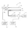
- (A) is a side view of the primary coil used for the non-contact power supply apparatus which concerns on one Example of this invention
- (B) is the top view. It is the layout of the non-contact electric power supply apparatus which tested in order to confirm an effect.
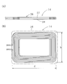
- (A) is a side view of the resonance coil of the non-contact power supply device
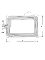
- (B) is a plan view. It is a top view of the secondary coil of the non-contact electric power supply apparatus.
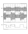
- (A)-(C) is a wave form diagram which shows the operation state of the non-contact electric power supply apparatus, respectively.
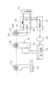
- a non-contact power supply apparatus 10 includes a primary coil 12 connected to a high-frequency power source 11 composed of an inverter (preferably 8 to 50 kHz), A secondary coil 13 that receives electric power generated from the primary coil 12, and a resonance coil 14 that is disposed between the primary coil 12 and the secondary coil 13 in contact with or close to the secondary coil 13.
- a high-frequency power source 11 composed of an inverter (preferably 8 to 50 kHz)
- a secondary coil 13 that receives electric power generated from the primary coil 12
- a resonance coil 14 that is disposed between the primary coil 12 and the secondary coil 13 in contact with or close to the secondary coil 13.
- a rectifier circuit 16 is connected to the secondary coil 13, and the output of the secondary coil 13 is converted into a direct current and supplied to a secondary battery 17 as a load.
- the DC voltage and current rectified by the rectifier circuit 16 are detected and input to the control circuit 18.
- the control circuit 18 performs digital processing and supplies it to the switching element circuit 20 via the photocoupler 19.
- an on signal and an off signal that are classified by the duty ratio are generated to increase or decrease the current flowing through the resonance coil 14.
- a capacitor 22 and a resistor 23 are connected to the resonance coil 14 in series. This state is shown in FIG. 6C.
- the switching element circuit 20 is turned off and only the resistor 23 is connected in series to the resonance coil 14, but in the period t1, the switching element circuit is connected. 20 is turned on, and another resistor is added in parallel to the resistor 23. Therefore, the resonance current can be controlled by changing the length ratio between t1 and t2.
- the current passing through the rectifier circuit 16 is detected by detecting the output current of the rectifier circuit 16 and feeding it back to the resonant coil 14. Can be made constant (or below a certain value). Further, the output voltage of the rectifier circuit 16 can be controlled to a predetermined value or less by detecting and feeding back the output voltage of the rectifier circuit 16 by the control circuit 18. In addition, when the secondary battery 17 is close to the completion of charging, the voltage increases, and this can be detected and the charging current can be reduced or reduced to zero.
- 6A shows the output voltage of the high frequency power supply 11
- FIG. 6B shows the current flowing through the resonance coil 14.
- the resonance coil 14 is provided with a resonance capacitor 18 a in series so that the current flowing through the resonance coil 14 resonates with the oscillation frequency f of the high-frequency power source (inverter) 11.
- the resonance frequency f1 formed by the resonance coil 14 and the capacitor 18a can be adjusted to (0.9 to 1.05) f by adjusting the capacitor 18a.
- the primary coil 12 attached to a fixed object for example, fixed to the building or arranged along the path of the work vehicle
- a vehicle driven by the secondary battery 17 for example, a work vehicle moving in the factory.
- the secondary coil 13 and the resonance coil 14 that are mounted on will be described.
- the areas of the secondary coil 13 and the resonance coil 14 in plan view are equal to or smaller than the area of the primary coil 12 in plan view, and the primary coil 12 preferably covers the resonance coil 14. .
- the secondary coil 13 and the resonance coil 14 in a plan view have a rectangular shape with rounded corners (having roundness), and are arranged with the same shape and area.
- the secondary coil 13 and the resonance coil 14 in plan view have widths a and b in the range of 350 to 600 mm and lengths c and d in the range of 350 to 650 mm in FIGS. Is in range.
- the width e of the primary coil 12 made of a hollow rectangle whose corners are arcuate in plan view is in the range of 350 to 600 mm, and is long.
- the thickness f is in the range of 350 to 800 mm.
- the length refers to the length in the traveling direction of the vehicle (that is, the length along the passage of the vehicle), and the width refers to the length in the direction orthogonal to the length (that is, the length along the width of the passage). .
- the primary coil 12 is formed by spirally winding a first litz wire 25 in a planar shape
- the resonant coil 14 is formed by winding coils 27 and 28 spirally wound in a plane on a second litz wire 26 in two layers.
- the secondary coil 13 is formed and two third litz wires 29 and 29a are arranged in parallel and spirally wound in a planar shape.
- the thickness of the first to third litz wires 25, 26, 29, and 29a is determined by the flowing current, but when charging the secondary battery 17 of the vehicle in the factory, for example, 100A specification (diameter is about 8). It is preferable to employ those having a thickness of ⁇ 9 mm and 14-22 SQ.
- a plurality of rod-shaped ferrite cores 31 cross about the winding (the first litz wire 25) of the primary coil 12 and are approximately 10 to It is provided at intervals of 50 mm.
- the rod-shaped ferrite core 31 completely covers the winding and protrudes further inside and outside. This prevents the magnetic field generated by the primary coil 12 from leaking to the back side of the primary coil 12 as much as possible.
- a gap S is provided between adjacent windings of the primary coil 12, that is, the first litz wire 25, to prevent interference between the first litz wires 25 as much as possible.
- the gap S is, for example, about 2 to 5 mm.
- the primary coil 12 is fixed on an insulating plate (for example, a glass epoxy substrate) 33, a rod-shaped ferrite core 31 is provided on the back of the insulating plate 33, and an aluminum plate 35 of 3 to 10 mm (preferably 5 to 8 mm) is provided on the back. Is provided.
- the aluminum plate 35 reinforces the entire primary coil 12 through the rod-shaped ferrite core 31 and can be screwed to the ceiling, wall, etc. of the building.
- the secondary coil 13 is formed by winding two litz wires 29, 29 a (third litz wire) or in parallel with each other, winding one litz wire 29, 29a is connected and used as an intermediate tap, and the rectifier circuit 16 by the two diodes 37 and 38 is comprised.
- the primary coil 12 has a width e of 400 mm, a length f of 600 mm (see FIG. 1), and the first litz wire 25 having a diameter of 8 to 9 mm is 10 turns by planar spiral winding. .
- a resonance coil 14 is disposed immediately below the primary coil 12, and a secondary coil 13 is disposed in contact with the resonance coil 14.
- the interval between the resonance coil 14 and the primary coil 12 was 50 mm.
- the planar dimensions of the resonance coil 14 and the secondary coil 13 were the same, the widths a and b were 400 mm, and the length was 600 mm.
- the resonance coil 14 is formed by winding a second litz wire (diameter 8 to 9 mm) 26 for eight turns and connecting the coils 27 and 28 in series to form two layers.
Landscapes
- Engineering & Computer Science (AREA)
- Power Engineering (AREA)
- Computer Networks & Wireless Communication (AREA)
- Mechanical Engineering (AREA)
- Transportation (AREA)
- Physics & Mathematics (AREA)
- Electromagnetism (AREA)
- Current-Collector Devices For Electrically Propelled Vehicles (AREA)
- Electric Propulsion And Braking For Vehicles (AREA)
- Charge And Discharge Circuits For Batteries Or The Like (AREA)
- Coils Of Transformers For General Uses (AREA)
Priority Applications (6)
| Application Number | Priority Date | Filing Date | Title |
|---|---|---|---|
| US14/416,743 US9716386B2 (en) | 2013-03-06 | 2014-03-05 | Contactless power supply system |
| JP2014546214A JP5707543B2 (ja) | 2013-03-06 | 2014-03-05 | 非接触電力供給装置 |
| KR1020157001610A KR20150023837A (ko) | 2013-03-06 | 2014-03-05 | 비접촉 전력 공급 장치 |
| CN201480001919.0A CN104488170A (zh) | 2013-03-06 | 2014-03-05 | 非接触电力供给装置 |
| EP14760172.8A EP2879273A4 (en) | 2013-03-06 | 2014-03-05 | CONTACTLESS ENERGY SUPPLY DEVICE |
| CN201611078801.5A CN106505643B (zh) | 2013-03-06 | 2014-03-05 | 非接触电力供给装置 |
Applications Claiming Priority (2)
| Application Number | Priority Date | Filing Date | Title |
|---|---|---|---|
| JP2013044743 | 2013-03-06 | ||
| JP2013-044743 | 2013-03-06 |
Publications (1)
| Publication Number | Publication Date |
|---|---|
| WO2014136839A1 true WO2014136839A1 (ja) | 2014-09-12 |
Family
ID=51491348
Family Applications (1)
| Application Number | Title | Priority Date | Filing Date |
|---|---|---|---|
| PCT/JP2014/055632 Ceased WO2014136839A1 (ja) | 2013-03-06 | 2014-03-05 | 非接触電力供給装置 |
Country Status (7)
| Country | Link |
|---|---|
| US (1) | US9716386B2 (enExample) |
| EP (1) | EP2879273A4 (enExample) |
| JP (2) | JP5707543B2 (enExample) |
| KR (1) | KR20150023837A (enExample) |
| CN (2) | CN106505643B (enExample) |
| MY (1) | MY172772A (enExample) |
| WO (1) | WO2014136839A1 (enExample) |
Cited By (1)
| Publication number | Priority date | Publication date | Assignee | Title |
|---|---|---|---|---|
| WO2017187611A1 (ja) * | 2016-04-28 | 2017-11-02 | 三菱電機エンジニアリング株式会社 | 無線電力伝送装置及び受信装置 |
Families Citing this family (12)
| Publication number | Priority date | Publication date | Assignee | Title |
|---|---|---|---|---|
| DE102014002876A1 (de) * | 2014-03-05 | 2015-09-10 | Supa Wireless Gmbh | Anordnung für eine induktive Energieübertragung |
| US9929606B2 (en) * | 2015-05-11 | 2018-03-27 | Qualcomm Incorporated | Integration of positioning antennas in wireless inductive charging power applications |
| EP3355325B1 (en) | 2015-09-24 | 2021-07-28 | FUJI Corporation | Coil for noncontact power supply and noncontact power supply system |
| US10878989B2 (en) * | 2016-07-13 | 2020-12-29 | Nippon Steel Corporation | Inductance adjusting device |
| US10144302B2 (en) | 2016-09-23 | 2018-12-04 | Qualcomm Incorporated | Twisted wire for power charging |
| JP6776889B2 (ja) * | 2016-12-27 | 2020-10-28 | 株式会社ダイフク | 搬送台車 |
| KR101806764B1 (ko) | 2017-02-13 | 2017-12-07 | 동원건설산업 주식회사 | 무선충전 급전장치용 리츠 와이어 단말부 보호 브라켓 |
| FR3065121B1 (fr) * | 2017-04-06 | 2020-10-02 | Dcns | Systeme de transmission d'energie electrique sans contact notamment pour drone |
| DE102017109818A1 (de) * | 2017-05-08 | 2018-11-08 | Liebherr-Verzahntechnik Gmbh | Ladeportal |
| JP6505820B1 (ja) * | 2017-12-18 | 2019-04-24 | 昭和電線ケーブルシステム株式会社 | 非接触給電装置およびコイル |
| EP3786985B1 (en) | 2019-08-28 | 2023-06-07 | Delta Electronics (Thailand) Public Co., Ltd. | Resonating inductor for wireless power transfer |
| PL243920B1 (pl) * | 2021-10-15 | 2023-10-30 | Siec Badawcza Lukasiewicz Inst Tele I Radiotechniczny | Układ zasilania indukcyjnego z izolacją wysokonapięciową |
Citations (6)
| Publication number | Priority date | Publication date | Assignee | Title |
|---|---|---|---|---|
| JP3442937B2 (ja) | 1996-08-26 | 2003-09-02 | 日立機電工業株式会社 | 地上移動体の非接触給電装置 |
| JP4318742B1 (ja) | 2008-10-06 | 2009-08-26 | 有限会社日本テクモ | 非接触電力供給装置 |
| JP2010016235A (ja) * | 2008-07-04 | 2010-01-21 | Panasonic Electric Works Co Ltd | 平面コイル |
| JP2010273441A (ja) * | 2009-05-20 | 2010-12-02 | Nippon Tekumo:Kk | 非接触電力供給装置 |
| JP2012120410A (ja) * | 2010-12-03 | 2012-06-21 | Fujitsu Ten Ltd | 受電装置、送電装置、及び無線電力伝送システム |
| JP2012249401A (ja) * | 2011-05-27 | 2012-12-13 | Nissan Motor Co Ltd | 非接触給電装置 |
Family Cites Families (17)
| Publication number | Priority date | Publication date | Assignee | Title |
|---|---|---|---|---|
| AU4093393A (en) * | 1993-05-03 | 1994-11-21 | Peter Bruce Clark | Power collector for inductive power transfer |
| JP2009158598A (ja) | 2007-12-25 | 2009-07-16 | Panasonic Electric Works Co Ltd | 平面コイル及びこれを用いた非接触電力伝送機器 |
| WO2010090539A1 (en) | 2009-02-05 | 2010-08-12 | Auckland Uniservices Limited | Inductive power transfer apparatus |
| JP5471283B2 (ja) | 2009-10-19 | 2014-04-16 | Tdk株式会社 | ワイヤレス給電装置、ワイヤレス受電装置およびワイヤレス電力伝送システム |
| JP2011229202A (ja) | 2010-04-15 | 2011-11-10 | Panasonic Corp | 無線電力伝送用コイル |
| CN101854086A (zh) * | 2010-04-30 | 2010-10-06 | 中山大学 | 一种高品质因数的无线能量传输设备 |
| US20110309689A1 (en) | 2010-06-17 | 2011-12-22 | Semiconductor Energy Laboratory Co., Ltd. | Electric power transmitting device, electric power receiving device, and power supply method using electric power transmitting and receiving devices |
| WO2012001758A1 (ja) * | 2010-06-28 | 2012-01-05 | 昭和飛行機工業 株式会社 | 非接触給電装置 |
| JP5653137B2 (ja) | 2010-08-31 | 2015-01-14 | キヤノン株式会社 | 給電装置及び方法 |
| JP4982598B2 (ja) * | 2010-09-07 | 2012-07-25 | 株式会社東芝 | 無線電力伝送システム、該システムの送電装置および受電装置 |
| JP5902693B2 (ja) | 2010-09-26 | 2016-04-13 | アクセス ビジネス グループ インターナショナル リミテッド ライアビリティ カンパニー | 選択的に制御可能な電磁気シールド |
| JP4835786B1 (ja) | 2010-12-01 | 2011-12-14 | パナソニック株式会社 | 非接触充電モジュール及び非接触充電機器 |
| US8800738B2 (en) | 2010-12-28 | 2014-08-12 | Tdk Corporation | Wireless power feeder and wireless power receiver |
| US9035500B2 (en) | 2011-03-01 | 2015-05-19 | Tdk Corporation | Wireless power feeder, wireless power receiver, and wireless power transmission system, and coil |
| US9136728B2 (en) * | 2011-04-28 | 2015-09-15 | Medtronic, Inc. | Implantable medical devices and systems having inductive telemetry and recharge on a single coil |
| WO2012157115A1 (ja) | 2011-05-19 | 2012-11-22 | トヨタ自動車株式会社 | 受電装置およびそれを備える車両、給電設備、ならびに給電システム |
| KR101339486B1 (ko) * | 2012-03-29 | 2013-12-10 | 삼성전기주식회사 | 박막 코일 및 이를 구비하는 전자 기기 |
-
2014
- 2014-03-05 JP JP2014546214A patent/JP5707543B2/ja active Active
- 2014-03-05 US US14/416,743 patent/US9716386B2/en active Active
- 2014-03-05 EP EP14760172.8A patent/EP2879273A4/en not_active Withdrawn
- 2014-03-05 WO PCT/JP2014/055632 patent/WO2014136839A1/ja not_active Ceased
- 2014-03-05 MY MYPI2015700226A patent/MY172772A/en unknown
- 2014-03-05 KR KR1020157001610A patent/KR20150023837A/ko not_active Ceased
- 2014-03-05 CN CN201611078801.5A patent/CN106505643B/zh not_active Expired - Fee Related
- 2014-03-05 CN CN201480001919.0A patent/CN104488170A/zh active Pending
-
2015
- 2015-01-16 JP JP2015006904A patent/JP6154835B2/ja active Active
Patent Citations (6)
| Publication number | Priority date | Publication date | Assignee | Title |
|---|---|---|---|---|
| JP3442937B2 (ja) | 1996-08-26 | 2003-09-02 | 日立機電工業株式会社 | 地上移動体の非接触給電装置 |
| JP2010016235A (ja) * | 2008-07-04 | 2010-01-21 | Panasonic Electric Works Co Ltd | 平面コイル |
| JP4318742B1 (ja) | 2008-10-06 | 2009-08-26 | 有限会社日本テクモ | 非接触電力供給装置 |
| JP2010273441A (ja) * | 2009-05-20 | 2010-12-02 | Nippon Tekumo:Kk | 非接触電力供給装置 |
| JP2012120410A (ja) * | 2010-12-03 | 2012-06-21 | Fujitsu Ten Ltd | 受電装置、送電装置、及び無線電力伝送システム |
| JP2012249401A (ja) * | 2011-05-27 | 2012-12-13 | Nissan Motor Co Ltd | 非接触給電装置 |
Non-Patent Citations (1)
| Title |
|---|
| See also references of EP2879273A4 |
Cited By (2)
| Publication number | Priority date | Publication date | Assignee | Title |
|---|---|---|---|---|
| WO2017187611A1 (ja) * | 2016-04-28 | 2017-11-02 | 三菱電機エンジニアリング株式会社 | 無線電力伝送装置及び受信装置 |
| JPWO2017187611A1 (ja) * | 2016-04-28 | 2018-05-10 | 三菱電機エンジニアリング株式会社 | 無線電力伝送装置及び受信装置 |
Also Published As
| Publication number | Publication date |
|---|---|
| EP2879273A1 (en) | 2015-06-03 |
| US20150207332A1 (en) | 2015-07-23 |
| EP2879273A4 (en) | 2016-04-27 |
| JP2015136287A (ja) | 2015-07-27 |
| US9716386B2 (en) | 2017-07-25 |
| JPWO2014136839A1 (ja) | 2017-02-16 |
| CN106505643A (zh) | 2017-03-15 |
| JP6154835B2 (ja) | 2017-06-28 |
| CN106505643B (zh) | 2019-02-19 |
| JP5707543B2 (ja) | 2015-04-30 |
| CN104488170A (zh) | 2015-04-01 |
| KR20150023837A (ko) | 2015-03-05 |
| MY172772A (en) | 2019-12-12 |
Similar Documents
| Publication | Publication Date | Title |
|---|---|---|
| JP6154835B2 (ja) | 非接触電力供給装置 | |
| JP2015136287A5 (enExample) | ||
| JP6371364B2 (ja) | 非接触電力供給装置 | |
| US10014105B2 (en) | Coil unit and wireless power transmission device | |
| US10002708B2 (en) | Coil unit and wireless power transmission device | |
| JP6191578B2 (ja) | ワイヤレス給電装置およびワイヤレス給電システム | |
| WO2012108432A1 (ja) | 非接触給電装置 | |
| JP2010093902A (ja) | 非接触電力供給装置 | |
| JP5646688B2 (ja) | 非接触給電システム | |
| US11043845B2 (en) | Power feeding device and wireless power transmission device | |
| US9331493B2 (en) | Electric load control apparatus | |
| JP5384195B2 (ja) | 非接触電力供給装置 | |
| JP6358098B2 (ja) | 給電装置および非接触電力伝送装置 | |
| JP6354437B2 (ja) | 非接触給電装置 | |
| Matsumoto et al. | Wireless power transfer system with passive boost topology for AGVs | |
| JP2013243890A (ja) | 非接触給電装置 | |
| US9991749B2 (en) | Coil unit, wireless power feeding device, wireless power receiving device, and wireless power transmission device | |
| JP5250867B2 (ja) | 誘導受電回路 | |
| JP2014128048A (ja) | 高周波電圧発生装置及び受給電システム | |
| JP6424710B2 (ja) | 非接触電力伝送用コイルおよび非接触電力伝送装置 | |
| JP2018196230A (ja) | 移動体用ワイヤレス給電システム | |
| JP2005102378A (ja) | 誘導受電回路 | |
| JP2006287987A (ja) | 無接触給電設備の2次側受電回路 |
Legal Events
| Date | Code | Title | Description |
|---|---|---|---|
| ENP | Entry into the national phase |
Ref document number: 2014546214 Country of ref document: JP Kind code of ref document: A |
|
| 121 | Ep: the epo has been informed by wipo that ep was designated in this application |
Ref document number: 14760172 Country of ref document: EP Kind code of ref document: A1 |
|
| ENP | Entry into the national phase |
Ref document number: 20157001610 Country of ref document: KR Kind code of ref document: A |
|
| WWE | Wipo information: entry into national phase |
Ref document number: 14416743 Country of ref document: US |
|
| REEP | Request for entry into the european phase |
Ref document number: 2014760172 Country of ref document: EP |
|
| WWE | Wipo information: entry into national phase |
Ref document number: 2014760172 Country of ref document: EP |
|
| WWE | Wipo information: entry into national phase |
Ref document number: IDP00201500518 Country of ref document: ID |
|
| NENP | Non-entry into the national phase |
Ref country code: DE |