WO2014136356A1 - 水圧転写用フィルムおよびそれを用いた転写被写体 - Google Patents
水圧転写用フィルムおよびそれを用いた転写被写体 Download PDFInfo
- Publication number
- WO2014136356A1 WO2014136356A1 PCT/JP2013/083935 JP2013083935W WO2014136356A1 WO 2014136356 A1 WO2014136356 A1 WO 2014136356A1 JP 2013083935 W JP2013083935 W JP 2013083935W WO 2014136356 A1 WO2014136356 A1 WO 2014136356A1
- Authority
- WO
- WIPO (PCT)
- Prior art keywords
- ink
- film
- hydraulic transfer
- absorbing layer
- layer
- Prior art date
- Legal status (The legal status is an assumption and is not a legal conclusion. Google has not performed a legal analysis and makes no representation as to the accuracy of the status listed.)
- Ceased
Links
Images
Classifications
-
- B—PERFORMING OPERATIONS; TRANSPORTING
- B44—DECORATIVE ARTS
- B44C—PRODUCING DECORATIVE EFFECTS; MOSAICS; TARSIA WORK; PAPERHANGING
- B44C1/00—Processes, not specifically provided for elsewhere, for producing decorative surface effects
- B44C1/16—Processes, not specifically provided for elsewhere, for producing decorative surface effects for applying transfer pictures or the like
- B44C1/165—Processes, not specifically provided for elsewhere, for producing decorative surface effects for applying transfer pictures or the like for decalcomanias; sheet material therefor
- B44C1/175—Transfer using solvent
Definitions
- the present invention relates to a hydraulic transfer film used in a hydraulic transfer method for imparting a design by transferring a pattern layer to a transfer subject having an uneven three-dimensional surface or curved surface, and the transfer subject.
- the hydraulic transfer method is known as a technique that can impart a design layer rich in design to a transfer subject having an uneven solid surface or curved surface.
- a method for forming a pattern layer on a water-soluble or water-swellable film such as a polyvinyl alcohol film as a support by a printing means such as gravure printing is used for the production of a film for hydraulic transfer used in the hydraulic transfer method.
- a method for forming a picture layer by an ink-jet method has been attracting attention with the recent increase in demand for production of various kinds of small lots.
- the pattern layer is formed by the inkjet method
- the pattern layer is formed by directly landing the ink on the polyvinyl alcohol film or the like as the support from the relationship of the viscosity, surface tension, solid content concentration, drying speed, etc. of the ink used in the inkjet method. Is difficult to form. For this reason, it is common to form an ink absorbing layer for absorbing an ink solvent on a polyvinyl alcohol film or the like as a support.
- This ink absorbing layer is obtained by dissolving a resin in a non-aqueous solvent that does not dissolve a water-soluble or water-swellable film such as polyvinyl alcohol, coating the surface of the support such as a polyvinyl alcohol film, and then drying. It is formed.
- Patent Document 1 Conventionally, as a film for hydraulic transfer used in the hydraulic transfer method, there is one described in Japanese Patent No. 395748 (Patent Document 1).
- This hydraulic transfer film includes a support film, an ink absorbing layer, and a pattern layer.
- the ink absorbing layer is made of a highly extensible resin such as a urethane resin, so that a three-dimensional surface or curved surface with unevenness is formed. It can be in close contact with the transfer subject.
- a resin having high extensibility such as urethane resin has elasticity like rubber, and a transfer subject having an uneven solid surface or curved surface is pressed against the hydraulic transfer film along the shape of the transfer subject. At this time, the ink absorbing layer tends to return to its original shape due to its elasticity, and the water pressure transfer film is wrinkled. Therefore, there is a problem in that the design layer is transferred to the transfer subject in a state where the hydraulic transfer film is wrinkled, and the design transferred by the design layer is damaged.
- the elastic force of the resin varies depending on the film thickness of the resin, if the resin film thickness is reduced to less than 1 ⁇ m, the elastic force of the resin can be reduced, but the performance of absorbing ink is reduced. There was a problem that an overflow occurred and a pattern layer could not be formed.
- an object of the present invention is to provide a hydraulic transfer film which does not cause wrinkles during the hydraulic transfer process and does not impair the transferred design.
- the hydraulic transfer film of the present invention is A water-soluble or water-swellable support film; After applying an acrylic resin dissolved in a non-aqueous solvent on one side of the support film, an ink absorbing layer formed by drying the non-aqueous solvent; And a pattern layer formed on the ink absorbing layer.
- the ink transfer layer formed by applying the acrylic resin dissolved in the non-aqueous solvent on one side of the support film and then drying the non-aqueous solvent is provided on the hydraulic transfer film. Therefore, the ink absorbing layer is easily deformed because it is softened when it is swollen and re-dissolved, and when the solvent component is dried, it retains its original shape and tries to return to the shape before softening. The power to do not work. Therefore, it can prevent that a wrinkle generate
- an acrylic resin dissolved in a non-aqueous solvent has a small increase in viscosity when polymerized and is easy to handle, so it can be easily applied to a water-soluble and water-swellable support film. .
- the pattern layer is formed by inkjet printing using an inkjet ink containing at least a pigment, a dispersant, an acrylic resin, and an organic solvent,
- the organic solvent uses a mixed solvent of glycol ester and glycol ether, or glycol ester or glycol ether as a main solvent.
- the pattern layer is formed by inkjet printing using an inkjet ink including at least a pigment, a dispersant, an acrylic resin, and an organic solvent, and the organic solvent is made of glycol ester and glycol ether. Since the mixed solvent, glycol ester, or glycol ether is used as the main solvent, the ink jet ink sufficiently penetrates into the ink absorbing layer and does not damage the ink absorbing layer by dissolution. Therefore, the ink-jet ink and the ink absorption layer are compatible with each other, and even a thin absorption layer hardly causes cracking or bleeding, and can stably achieve both printability and transferability.
- the ink absorbing layer has a thickness of 2 to 7 ⁇ m.
- the thickness of the ink absorbing layer is 2 to 7 ⁇ m, it is easy to achieve both the pattern formation in which cracks are not noticeable and the transfer stability without wrinkles, and a high-quality transfer subject is obtained. It becomes possible.
- the support film is a strip having a certain width
- the support film, the ink absorption layer, and the pattern layer are laminated in this order, and the width of the support film is larger than the widths of the ink absorption layer and the pattern layer.
- the support film has a strip shape having a certain width, and is laminated in the order of the support film, the ink absorption layer, and the pattern layer, and the width of the support film is the ink absorption layer and the pattern. Since the support film is closest to the guide chain in the hydraulic transfer film when it floats on the water tank, the entire width of the contact surface will be reduced when the hydraulic transfer film comes into contact with the guide chain. Becomes a support film, and even if a residual film adheres, it can be easily removed in the water tank.
- the support film may be curled due to the hardness of each layer.
- the back surface of the support film absorbs water by softening and softens, the surface is curled so that the surface is wound inward in order to maintain the hardness as it is. Therefore, the part which contacts a guide chain can be reliably made into only a support body film, and the removal of an adhesion residual film can be made easy.
- the transfer subject of the present invention is formed using any one of the above hydraulic transfer films, and the surface of the transfer subject is formed in the order of a pattern layer and an ink absorbing layer.
- the ink absorbing layer covers the surface of the transfer subject. Therefore, the pattern layer is hardly peeled off from the transferred material, and is hardly damaged by an external force.
- topcoat processing transparent protective layer formation processing
- the ink absorption layer easily absorbs the solvent for the topcoat, so that the topcoat does not cause unevenness due to the solvent being repelled on the surface of the transfer subject. It is possible to obtain a transfer product with good adhesion and good adhesion.
- the manufacturing method of the hydraulic transfer film of this invention is Applying an acrylic resin dissolved in a non-aqueous solvent on one side of a water-soluble or water-swellable support film; Drying the acrylic resin coated on the support film to form an ink absorbing layer; And a step of forming a pattern layer on the ink absorbing layer by an ink jet method.
- a step of applying an acrylic resin dissolved in a non-aqueous solvent on one side of a water-soluble or water-swellable support film, and drying the acrylic resin applied to the support film Since it has a step of forming an ink absorption layer and a step of forming a pattern layer on the ink absorption layer by an ink jet method, it is dissolved in a non-aqueous solvent that has a small increase in viscosity when polymerized and is easy to handle.
- An acrylic resin can be easily applied to a water-soluble and water-swellable support film to form an ink absorbing layer, and wrinkles are generated during the hydraulic transfer process, and the transferred design is damaged. A film for hydraulic transfer that can prevent this can be produced.
- the hydraulic transfer film of the present invention does not generate wrinkles during the hydraulic transfer process and does not impair the transferred design, and clearly uses the same.
- a printed transfer subject can be realized.
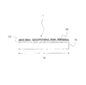
- FIG. 1 is a longitudinal sectional view of a hydraulic transfer film according to a first embodiment of the present invention.
- FIG. 2 is a schematic view seen from the upper surface of the hydraulic transfer film according to the second embodiment of the present invention.
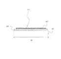
- FIG. 3 is a longitudinal sectional view of the hydraulic transfer film as seen from the line AA.
- the hydraulic transfer film 1 As shown in FIG. 1, the hydraulic transfer film 1 according to the first embodiment of the present invention includes a support film 10 made of a water-soluble or water-swellable film, an ink absorbing layer 20, and a pattern layer 30. Yes.
- This hydraulic transfer film 1 is formed by laminating an ink absorbing layer 20 and a pattern layer 30 in this order on a support film 10, and the width of the support film 10, the ink absorbing layer 20 and the pattern layer 30 in the width direction W is the same. All are formed to be the same.
- width direction as used in this specification is a direction shown by the arrow W, and the size of the width direction W refers to the length of each layer in this direction.
- the support film 10 has a strip shape having water solubility or water swellability, and is made of, for example, a resin such as polyvinyl alcohol, polyvinyl pyrrolidone, dextrin, gelatin, glue, sodium alginate, hydroxyethyl cellulose, acetyl butyl cellulose, or the like.
- the thickness of the support film 10 is preferably 10 to 100 ⁇ m. In this embodiment, the support film 10 made of a polyvinyl alcohol resin having a thickness of 30 ⁇ m is used.
- the support film 10 can be manufactured using a known technique as disclosed in, for example, Japanese Patent Application Laid-Open No. 2005-60636.
- the ink absorbing layer 20 is formed by applying a coating solution obtained by dissolving an acrylic resin in a non-aqueous solvent on one side of the support film 10 and evaporating the non-aqueous solvent by a drying means such as an oven. .
- acrylic resin used for the ink absorbing layer 20 examples include poly (meth) acrylate, poly (meth) butyl acrylate, (meth) methyl acrylate- (meth) butyl acrylate copolymer, (meth )
- One kind alone or a mixture of two or more kinds such as methyl acrylate- (meth) acrylate 2-hydroxyethyl copolymer is used.
- a copolymer of butyl acrylate and methyl (meth) acrylate is used.
- Non-aqueous solvents for dissolving acrylic resins include monohydric alcohols such as methyl alcohol, ethyl alcohol, propyl alcohol, and butyl alcohol, polyhydric alcohols such as ethylene glycol, propylene glycol, and glycerin, acetone, methyl ethyl ketone, methyl Ketones such as isobutyl ketone and cyclohexanone, ethyl ether, isopropyl ether, ethylene glycol mono-methyl ether, ethylene glycol mono-ethyl ether, ethylene glycol mono-butyl ether, diethylene glycol mono-methyl ether, diethylene glycol mono-ethyl Ethers, ethers such as diethylene glycol mono-butyl ether, ethyl acetate, butyl acetate, ethylene glycol mono-ethyl ether Ether acetate, ethylene glycol mono-butyl ether acetate, diethylene glycol mono
- the thickness of the ink absorbing layer 20 of the transfer film used other than the hydraulic transfer film 1 is generally 10 to 30 ⁇ m.
- the thickness of the ink absorbing layer 20 is desirably 2 to 7 ⁇ m.
- the thickness of the ink absorbing layer 20 is 2 ⁇ m or less, if the amount of ink is large, the ink absorbing layer 20 cracks over the entire thickness of the layer, and the transfer quality deteriorates.
- the thickness of the ink absorbing layer 20 If the thickness is 7 ⁇ m or more, there is a high possibility that wrinkles will occur during transfer.
- a copolymer of butyl acrylate and methyl (meth) acrylate is used as the resin component of the ink absorption layer 20
- ethyl acetate is used as the main solvent
- the resin of the support film 10 is used as a resin.
- Polyvinyl alcohol resin was used, but the thin ink absorbing layer 20 having a thickness of 2 to 7 ⁇ m could be stably formed. For this reason, it becomes easy to achieve both the pattern formation in which cracks are not noticeable and the transfer stability without wrinkles, and a high-quality transfer body can be obtained.
- the thickness of the ink absorbing layer 20 is desirably in the range of 2 to 5 ⁇ m.
- an acrylic resin is used as the resin component of the ink absorbing layer 20, and a small amount ( ⁇ 1%) of an isocyanate solution diluted with an ethyl acetate solvent is added to a coating solution containing ethyl acetate as a solvent. It is possible to obtain a hydraulic transfer film 1 that has both printability and flexibility in the transfer process by coating the surface of the alcohol support film 10 and drying it to form the ink absorbing layer 20. Become. By adding the isocyanate solution, the ink absorbing layer 20 can partially form a three-dimensional network structure with isocyanate groups. Since the optimum addition amount of the isocyanate solution varies depending on the acrylic resin component and the activator component described later, it is desirable to add an amount of the isocyanate solution derived from experiments in order to further improve the printability and transferability.
- a coating solution made of an ethyl acetate solvent was prototyped and examined using a polyurethane resin that is generally well used as the material of the ink absorbing layer 20.
- the ink absorption layer using polyurethane resin has elasticity like rubber, and when the transfer subject is pressed against the film, it stretches along the shape of the transfer subject, but it tries to return to its original shape by its elastic force. As a result, the film was transferred with wrinkles on it, which was inappropriate.
- coating means such as gravure coating, roll coating, die coating, and bar coating can be used. Is generally packaged in a roll shape, and a treatment method called roll-to-roll is preferable, and a coating means such as gravure coating, roll coating, and die coating is preferable. In this embodiment, a gravure coating method is used.
- the ink absorbing layer 20 is formed by applying a coating solution obtained by dissolving an acrylic resin in a non-aqueous solvent on the support film 10 and then drying by heating with a drying means such as an oven.
- a drying means such as an oven.
- the heating temperature is 40 to 80 ° C. and the heating time is 1 to 10 minutes so that the support film 10 does not change due to heat drying during the time it softens, dissolves and swells after landing. Preferably there is.
- it is dried by heating in an oven at 80 ° C. for 1 minute.
- the support film 10 swells and stretches after landing, but if the ink absorbing layer 20 is not sufficiently flexible, the transfer subject is placed on the hydraulic transfer film 1. When pressed, the water pressure transfer film 1 is wrinkled and transferred to the transfer subject as it is, so that the design is damaged.
- the ink absorbing layer 20 In order to prevent the quality of the design transferred to the transfer subject from deteriorating, it is necessary to provide the ink absorbing layer 20 with a certain degree of flexibility, which does not hinder the extending behavior of the support film 10 in the hydraulic transfer process. Thus, it is necessary to set a glass transition point having a correlation with the flexibility of the resin. Specifically, the glass transition point of the ink absorption layer 20 is set to be equal to or lower than the glass transition point of the support film 10.
- the glass transition point of the ink absorbing layer 20 is too low, tackiness is exhibited in the ink absorbing layer 20, so that blocking is indispensable when the hydraulic transfer film 1 is rolled.
- a protective member is required as a countermeasure against blocking, resulting in an increase in cost. Therefore, it is preferable that the glass transition point of the ink absorption layer 20 is not less than room temperature at which tackiness is relatively suppressed, specifically, the glass transition point is 22 ° C. or more as a design value.
- the glass transition point can be adjusted by designing the molecular structure at the time of synthesizing the acrylic resin, adjusting the polymerization degree, etc.
- phthalic acid esters such as dioctyl phthalate, adipic acid ester It can be carried out by adding a plasticizer such as a kind. In this embodiment, dioctyl phthalate is added as a plasticizer.
- the glass transition point is measured using a differential scanning calorimetry (DSC) method, and the intermediate point of the calorific value change amount is used as the glass transition point in a region where the calorific value changes.
- DSC differential scanning calorimetry
- the glass transition point of the support film 10 is 70 ° C.
- the glass transition point of the ink absorbing layer 20 is preferably 30 ° C. to 60 ° C., and the glass transition point is 55 ° C. from the viewpoint of blocking. It is adjusted so that.
- Table 1 shows the results of evaluating the weight average molecular weight and printability (landing diameter, blur) of the acrylic resin used in the ink absorbing layer 20.
- the molecular weight was adjusted according to the synthesis environmental conditions such as the amount of the reaction initiator, the reaction time, and the temperature.
- the light scattering method was used for measuring the molecular weight.
- the thickness of the ink absorbing layer 20 was 5 ⁇ m.
- the impact diameter when one drop is ejected is estimated by microscopic observation, and the proportionality coefficient when the nozzle diameter is “1” (for example, “2” when the impact diameter of the ink ejected from the inkjet head having a nozzle diameter of 20 ⁇ m is 40 ⁇ m. ”And“ 3 ”in the case of 60 ⁇ m.
- a weight average molecular weight of 50,000 or more is preferable, and a weight average molecular weight of 100,000 or more, which decreases the landing diameter in order to increase the resolution of the pattern layer 30, is more preferable. Coating becomes difficult. For this reason, when handling is considered, a weight average molecular weight of 500,000 or less that gives a viscosity of 1 Pa ⁇ s or less is more preferable.
- the pattern layer 30 is a solid content remaining on the ink absorption layer 20 after the solvent component of the ink composition is absorbed by the ink absorption layer 20, and the ink composition is discharged from the ink jet device to the ink absorption layer 20. Form. Therefore, since the solid material such as the color material component and the resin contained in the ink becomes a constituent of the pattern layer 30, the color developability and the film thickness of the pattern layer 30 depend on the concentration of the color material component and the resin component contained in the ink. Is decided.
- a solvent component of the ink that does not dissolve the ink absorption layer 20.
- a solvent component in this embodiment, a mixed solvent of a glycol ether solvent and a glycol ester solvent is used.
- a trace amount of a surfactant or the like for preventing drying or improving leveling may be added as necessary.
- the film thickness of the picture layer 30 is preferably in the range of 1 ⁇ m to 10 ⁇ m. This is because, in the water pressure transfer step, the water pressure transfer film 1 absorbs water and swells and expands about 1.4 times, so that the film thickness of the water pressure transfer film 10 is larger than that used in household printers. However, if the film thickness of the hydraulic transfer film 10 becomes too thick, the behavior of the hydraulic transfer film 1 after landing in the hydraulic transfer process is hindered, or wrinkles are formed on the hydraulic transfer film 1. This is because it may be generated.
- the pattern layer 30 is formed to be 3 to 4 ⁇ m.
- the non-aqueous ink jet ink composition according to the present invention includes at least a pigment, a dispersant for dispersing the pigment, an acrylic resin, and an organic solvent.
- a pigment for dispersing the pigment
- an acrylic resin for dispersing the pigment
- an organic solvent for dispersing the pigment
- each component will be described.
- the pigment used in the non-aqueous inkjet ink composition is not particularly limited, and an inorganic pigment or an organic pigment can be appropriately selected.
- inorganic pigments include carbon black, titanium oxide, zinc oxide, iron oxide, kaolinite, barium sulfate, calcium carbonate, silica, alumina, red pepper, chrome vermilion, chrome lead, chrome yellow, cadmium yellow, titanium yellow, Examples thereof include chromium oxide, cobalt green, cobalt blue, ultramarine blue, and bitumen.
- organic pigments examples include azo pigments such as monoazo pigments, diazo pigments, diazo condensation pigments, and azomethine pigments, isoindolinone pigments, isoindoline pigments, quinophthalone pigments, anthraquinone pigments, quinacridone pigments, imidazolone pigments, benzimidazolone pigments, Examples thereof include polycyclic pigments such as perinone pigments, perylene pigments, indigo pigments, thioindigo pigments, oxazine pigments, dioxazine pigments, and phthalocyanine pigments.
- azo pigments such as monoazo pigments, diazo pigments, diazo condensation pigments, and azomethine pigments
- isoindolinone pigments isoindoline pigments
- quinophthalone pigments anthraquinone pigments
- quinacridone pigments imidazolone pigments
- benzimidazolone pigments examples thereof
- These pigments can be used alone or in combination of two or more.
- the average primary particle diameter of the pigment after the dispersion treatment is preferably 50 to 200 nm, more preferably 60 to 150 nm in consideration of dispersibility and dischargeability.
- the average primary particle diameter of the pigment is smaller than the above range, the cohesiveness increases or the color developability deteriorates. On the other hand, if it is larger than the above range, nozzle clogging is likely to occur, and the discharge performance becomes unstable.
- the blending amount in the ink composition is preferably 1 to 15% by weight, more preferably 2 to 10% by weight.
- the amount of the pigment is less than the above range, the color developability deteriorates and only a light color can be expressed. Conversely, when it exceeds the above range, the viscosity stability of the ink composition itself deteriorates and the ink quality is sufficiently maintained. It ’s gone.
- the reactive functional groups hydroxyl group, carboxy group, sulfonic acid group, etc.
- the interaction with the pigment dispersant is preferably increased. Even if there is no reactive functional group, the reactive functional group can be introduced by performing surface treatment such as oxygen plasma treatment or UV irradiation treatment.
- pigment dispersant As the pigment dispersant used in the non-aqueous ink jet ink composition, an ionic surfactant, an anionic or cationic polymer compound, or the like can be used.
- a polymer compound in which a basic functional group is contained in a molecular chain is preferable because it has a good adsorptivity on a pigment surface in an organic solvent and provides a stable dispersion effect.
- the pigment dispersant must be appropriately selected according to the type of pigment and the type of organic solvent used.
- the blending amount of the pigment dispersant in the ink composition is preferably in the range of 10 to 100% by weight, more preferably in the range of 15 to 80% by weight, with respect to the inorganic pigment. Is preferably added in the range of 0.5 to 8% by weight, more preferably in the range of 1 to 5% by weight. If it is smaller than the above range, the desired dispersion performance is not exhibited and the cohesiveness becomes high. On the other hand, if it is larger than the above range, the viscosity becomes high, resulting in unstable ejection properties or nozzle clogging.
- Binder resin As the binder resin contained in the non-aqueous ink jet ink composition, it is indispensable to satisfy both the restrictive conditions required from the viewpoint of ink jet discharge properties and the restrictive conditions required from the viewpoint of drawing properties on the hydraulic transfer film 1. It is. With respect to the ejection performance, first, it must be in a viscosity range suitable for ejection corresponding to the ink jet apparatus, with little variation in ejection state and high stability over time. For this purpose, it is desirable to use a resin having a molecular weight that is not too high and that has little variation in molecular structure and degree of polymerization.
- the resin in order to improve the followability of the landing shape with respect to the extension behavior of the flexible ink absorbing layer 20, it is important that the resin does not have a too high molecular weight and has a high degree of freedom in molecular design. .
- the binder resin contained in the inkjet ink composition used in the present invention is as follows. Acrylic resin is most preferred.
- the acrylic resin contained in the inkjet ink composition can be obtained by copolymerizing a single monomer or a plurality of monomers by known radical polymerization.
- the monomer include acrylic acid esters such as methyl acrylate, ethyl acrylate, isopropyl acrylate, butyl acrylate, 2-ethylhexyl acrylate, methyl methacrylate, ethyl methacrylate, isopropyl methacrylate, butyl methacrylate, methacrylic acid.
- methacrylic acid esters such as isobutyl acid, cyclohexyl methacrylate, 2-ethylhexyl methacrylate, lauryl methacrylate, and stearyl methacrylate.
- monomers having a functional group can be used, for example, carboxyl group-containing monomers such as acrylic acid, methacrylic acid, maleic acid, and fumaric acid, 2-hydroxyethyl acrylate, 2-hydroxypropyl acrylate, and the like.
- the weight average molecular weight of the acrylic resin contained in the ink jet ink composition used in the present invention is preferably in the range of 5000 to 20000, and more preferably in the range of 7000 to 15000.
- the weight average molecular weight of the acrylic resin contained in the inkjet ink composition is smaller than this range, the inkjet ink has no film forming property, color fixing property, and glossiness.
- the weight average molecular weight of the acrylic resin contained in the ink-jet ink composition is larger than the above range, nozzle clogging is likely to occur, and ejection properties become unstable.
- the weight average molecular weight of the ink binder resin is preferably lower than the weight average molecular weight of the acrylic resin of the ink absorbing layer 20.
- the pattern layer 30 and the ink absorption layer 20 of the hydraulic transfer film 1 are softened by coating an activator made of an organic solvent in the transfer step.
- the weight average molecular weight of the binder resin of the pattern layer 30 is higher than the weight average molecular weight of the acrylic resin of the ink absorption layer 20, the portion of the pattern layer 30 is not easily softened by the activator, and the pattern layer Since the active agent is prevented from uniformly penetrating into the ink absorbing layer 20 located below 30, the difference in flexibility (attachment at the time of transfer) increases from place to place due to the difference in pattern density. It is.
- the organic solvent can be appropriately selected depending on the characteristics of the hydraulic transfer film.
- the blending amount of the acrylic resin in the inkjet ink composition is preferably in the range of 2 to 8% by weight.
- the blending amount of the acrylic resin is less than this range, there is a problem that the shape retention after landing on the ink absorbing layer 20 is weak or the fixability of the pigment is deteriorated.
- the viscosity of the inkjet ink composition is increased, and the ejection stability of the inkjet is deteriorated.
- ester resin urethane resin, rosin resin, alkyd resin, styrene-acrylic resin, cellulose resin, etc. is added within the range where ejection performance and drawing performance do not deteriorate.
- ejection performance and drawing performance do not deteriorate.
- the main solvent of the organic solvent contained in the non-aqueous ink jet ink composition of the present invention uses a glycol ester solvent and a glycol ether solvent.
- the glycol ester solvent and glycol ether solvent can dissolve the pigment, the dispersant for dispersing the pigment, and the acrylic resin, and can provide solution characteristics suitable for inkjet discharge.
- glycol ester solvents examples include ethylene glycol monomethyl ether acetate, ethylene glycol monoethyl ether acetate, ethylene glycol mono-n-butyl ether acetate, diethylene glycol monoethyl ether acetate, diethylene glycol mono-n-butyl ether acetate, propylene glycol monomethyl ether acetate. And dipropylene glycol monomethyl ether acetate. Since the solvent of the glycol ester solvent has good resin solubility, even an acrylic resin having a high molecular weight can be easily dissolved and dispersed uniformly, and the application range of the acrylic resin is expanded.
- the glycol ester solvent is not only absorbed by the ink absorbing layer 20 described above, but also has an effect of improving the adhesion between the binder resin in the ink and the ink absorbing layer 20 by dissolving a part of the surface layer. Therefore, it is preferred that the solvent contains a glycol ester solvent.
- diethylene glycol mono-n-butyl ether acetate and propylene glycol monomethyl ether acetate are preferable because they can stably disperse the binder resin and have a high adhesion effect with the ink absorbing layer 20.
- Glycol ether solvents are often used as solvents for inkjet inks. This is because there are multiple solvents with different boiling points related to problems such as clogging of inkjet nozzles due to drying and viscosities that are indicators for stably discharging fine droplets from the inkjet head, and their mixing properties are good, This is because a plurality of glycol ether solvents are often mixed and blended in a form that matches the characteristics of the inkjet head and the usage environment.
- Examples of the low-boiling glycol ether solvent that can contribute to the reduction in the viscosity of the entire inkjet ink composition include ethylene glycol monomethyl ether (124 ° C.), ethylene glycol monoethyl ether (135 ° C.), and ethylene glycol mono Isopropyl ether (144 ° C), ethylene glycol mono-n-propyl ether (152 ° C), ethylene glycol mono-n-butyl ether (171 ° C), propylene glycol monomethyl ether (121 ° C), propylene glycol monoethyl ether (133 ° C) , Propylene glycol mono-n-propyl ether (150 ° C.), propylene glycol mono-n-butyl ether (170 ° C.), dipropylene glycol dimethyl ether (171 ° C.), etc. Include ( Figures in parentheses following the solvent name indicate the boiling point). Of these, propylene glycol monomethyl ether and prop
- the ink absorbing layer 20 is an acrylic resin
- diethylene glycol monoethyl ether and diethylene glycol mono-n-butyl ether are preferable from the viewpoint of permeability to the ink absorbing layer 20.
- the ink for ink jet sufficiently penetrates into the ink absorbing layer 20 and damages the ink absorbing layer 20 by dissolution. There is no. Therefore, the ink for ink jet and the ink absorbing layer 20 are compatible with each other, and even a thin absorbing layer does not easily cause cracking or bleeding, and can stably achieve both printability and transferability.
- Ink-jet ink suitable for the above can be prepared.
- the above-mentioned material components are stirred and dispersed using a dispersing machine such as a bead mill, a ball mill, a sand mill, an attritor, or a roll mill so that the viscosity becomes 3 to 10 mPa ⁇ s. It can be obtained by adjusting to The stirred and dispersed ink composition is filtered through a filter such as a membrane filter or a cartridge filter, and large particles are removed to obtain a target non-aqueous ink jet ink composition.
- a dispersing machine such as a bead mill, a ball mill, a sand mill, an attritor, or a roll mill so that the viscosity becomes 3 to 10 mPa ⁇ s. It can be obtained by adjusting to The stirred and dispersed ink composition is filtered through a filter such as a membrane filter or a cartridge filter, and large particles are removed to obtain a target non-aqueous ink jet ink composition.
- Inkjet printing on hydraulic transfer film 1 Ink jet printing on the hydraulic transfer film 1 using the non-aqueous ink jet ink composition according to the present invention ejects fine droplets of the ink jet ink composition by an ink jet apparatus and lands on the ink absorbing layer 20. It is formed by letting.
- As the ink jet device various ink jet driving methods such as an electrostatic suction type and a piezoelectric method can be adopted.
- Pigment Blue 15 4 as a pigment is 10% by weight
- Dispersbyk-2001 manufactured by BYK Chemie is used as a pigment dispersant in an amount of 8% by weight and propylene glycol monomethyl ether acetate in a ratio of 82% by weight and dispersed for 10 hours.
- a pigment dispersion was obtained.
- a resin solution of an acrylic copolymer was prepared by radical polymerization using monomers of butyl acrylate and diethylaminoethyl methacrylate in a propylene glycol monomethyl ether acetate solvent.
- the resin liquid was obtained by solid content concentration 50% about five types whose weight average molecular weights are (A) 4400, (B) 9800, (C) 18000, (D) 25000, (E) 38000.
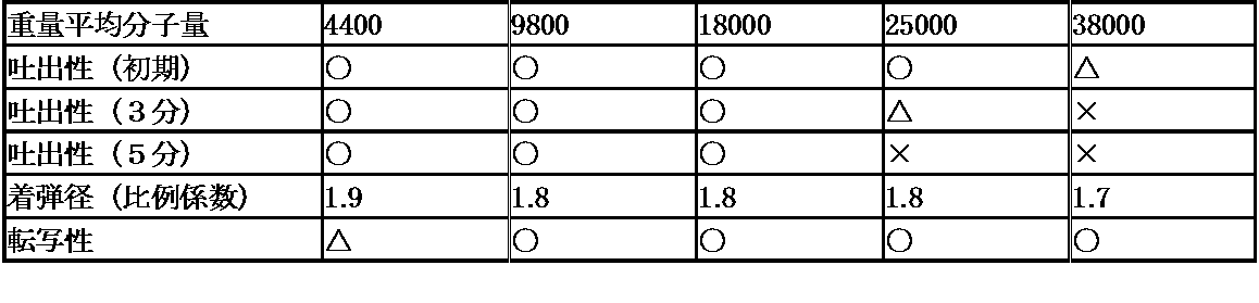
- Table 2 shows the molecular weight of the acrylic resin, which is the binder resin in the preparation example of the hydraulic transfer film 1, and the evaluation results of the discharge property, the contact elasticity, and the transfer property. Hereinafter, the evaluation result will be described.
- dischargeability Using an inkjet discharge evaluator, discharge stability in steady state by observing the flight state and measuring the landing position when an inkjet ink composition is discharged toward a specified position on a glass substrate It was confirmed. In addition, the discharge was stopped once, and after 3 minutes and then again after 5 minutes, the stability over time of the discharge was also confirmed. Judgment criteria are as follows.
- the inks of a plurality of colors are dripped almost simultaneously without going through a drying step.
- the thickness of the ink absorbing layer 20 was made in the range of 1 to 10 ⁇ m using a plurality of bar coaters, and the printability and transferability were examined.
- Table 3 shows the ink absorption layer 20 of the hydraulic transfer film 1 of the above preparation example and the evaluation results of printability and transferability.
- the hydraulic transfer film 1 is attached to a coating device that is a gravure coater, and an activator is applied to the surface of the support film 10 on which the pattern layer 30 and the ink absorbing layer 20 are formed.
- the solvent used for the activator can be selected from various solvents as long as it is a non-aqueous solvent.
- the pattern layer is used. 30 and the component capable of redissolving the ink absorbing layer 20, specifically, the component of the ink ejected from the ink jet apparatus to form the pattern layer 30, or the support for forming the ink absorbing layer 20 It is preferable that the solvent component contained in the coating liquid applied to the body film 10 is included.
- the activator preferably contains a main solvent contained in a coating liquid applied to the support film 10 in order to form the ink absorbing layer 20.
- the pattern layer 30 is made thinner than the ink absorption layer 20 and the ink absorption layer 20 below the pattern layer 30 is activated because the activator is supplied through the pattern layer 30. This is because it is difficult to select a component that is more easily activated in the ink absorbing layer 20 than in the pattern layer 30.
- the hydraulic transfer film 1 is conveyed into the water tank so that the back side of the activator-coated surface of the hydraulic transfer film 1 is landed.
- the water tank is always adjusted to have a constant flow rate and flow in one direction, and the hydraulic transfer film 1 is conveyed along the flow of the water.
- the hydraulic transfer film 1 swells and softens as the support film 10 absorbs water.
- the hydraulic transfer film 1 expands, and its end portion comes into contact with the guide chain in the water tank, and its size is defined.
- the design of the pattern layer 30 formed on the support film 10 is transferred by pressing the transfer subject conveyed from the same direction as the conveyance direction onto the softened hydraulic transfer film 1 at an angle of about 45 °.
- the transfer subject to which the design of the pattern layer 30 is transferred is washed with running water to wash away the unnecessary support film 10, and after drying, a topcoat agent (transparent protective layer forming agent) composed of urethane resin or the like is formed. Coated.
- One of the features of the inkjet method is to simultaneously eject multicolor ink and form the pattern layer 30 in a short time. To achieve this, the ink ejected from the inkjet device is absorbed quickly. If the ink absorbing layer 20 is required to have such characteristics, and the ink absorption is insufficient, the ink absorbing layer 20 is largely cracked as described above, and leakage occurs and a pattern cannot be formed. On the other hand, if the thickness of the ink absorption layer 20 is increased in order to increase the ink absorbability, the film is wrinkled in the subsequent transfer process, and the design of the transfer subject is impaired.
- the viscosity of the ink itself to be printed is high and solidifies without flowing even after printing, so it is necessary to form a pattern directly on a water-soluble or water-swellable film. Can do.
- the ink viscosity used is low and the solid content concentration is low, so that the liquid droplets wet and spread before drying and solidification, so the pattern is drawn directly on a water-soluble or water-swellable film. It is difficult. Therefore, in order to solidify while maintaining a state close to the droplet landing diameter immediately after landing, it is necessary to provide the ink absorbing layer 20 on the surface of the transfer film to be printed. That is, in order to form a high-definition decorative pattern on a transfer film by inkjet printing, the transfer film having the ink absorbing layer 20 is indispensable.
- the original purpose of the ink absorbing layer 20 is as described above, but from the application of hydraulic transfer, it must not only absorb ink but also have sufficiently extensible material properties. This is because, when the transfer subject is pressed against the transfer film, if it does not come in close contact with the shape of the transfer subject without causing wrinkles, the quality of the pattern may be deteriorated. In order to impart extensibility to materials, it is necessary to design materials such as softening the molecular structure, reducing the molecular weight, and suppressing intermolecular interactions.
- the film strength of the transfer film tends to be weak, so that the resistance to the solvent is weakened, and there is a concern that the ink having strong solubility is eroded.
- the ink absorbing layer 20 is formed by a material design that emphasizes extensibility suitable for the hydraulic transfer process, and as a result, the ink absorbing layer 20 of general inkjet paper is affected by the ink permeability and the dissolving power. Because the power is different. If the penetrating power is weak, the ink cannot be absorbed completely and the shape is blurred.
- the ink absorbing layer itself is melted and the film is damaged. That is, it is necessary to recognize that the ink absorption layer 20 for hydraulic transfer is different from the ink absorption layer of general inkjet paper, and the ink composition should be adjusted to match the ink absorption layer 20 for hydraulic transfer. Thus, high quality images can be realized on the transfer film.
- the present invention has been made in view of the above-described problems, and is a film for hydraulic transfer that can form a clear pattern by an inkjet method and does not damage the design without wrinkling the film during the hydraulic transfer process. 1 can be provided.
- the hydraulic transfer film 1 is provided with the ink absorbing layer 20 formed on one surface of the support film 10 with an acrylic resin dissolved in a non-aqueous solvent. Since it is softened in the redissolved state, it is easily deformed, and when the solvent component is dried, the force for maintaining the shape as it is and returning to the shape before softening does not work. Therefore, it can prevent that a wrinkle generate
- the acrylic resin dissolved in the non-aqueous solvent has a small increase in viscosity when polymerized and is easy to handle, it can be easily applied to the water-soluble and water-swellable support film 10. it can.
- the organic solvent used in the pattern layer 30 is a mixed solvent of glycol ester and glycol ether, or glycol ester or glycol ether as a main solvent
- the ink for inkjet is sufficiently applied to the ink absorbing layer 20. It penetrates and does not damage the ink absorbing layer 20 by dissolution. Therefore, the ink-jet ink and the ink absorbing layer 20 are compatible with each other, and even a thin absorbing layer is less likely to be cracked or smudged, so that both printability and transferability can be stably achieved.
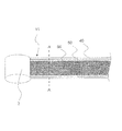
- FIG. 2 is a schematic view seen from the upper surface of the hydraulic transfer film 11 according to the second embodiment of the present invention.
- FIG. 3 is a longitudinal sectional view of the hydraulic transfer film 11 as seen from the line AA.
- the hydraulic transfer film 11 of the second embodiment includes a support film 40, an ink absorption layer 50, and a pattern layer 60.
- the support film 40, the ink absorption layer 50, and the pattern layer 60 of the hydraulic transfer film 11 of the present embodiment are the same as the support film 10, the ink absorption layer 20, and the pattern layer 30 of the hydraulic transfer film 1 of the first embodiment.
- the same components and methods are used, and the description of the first embodiment is used for overlapping portions.
- the hydraulic transfer film 11 is in the form of a roll wound around a roll 2, and the ink absorbing layer 50 and the pattern layer 60 are laminated on the support film 40 in this order. Moreover, as shown in FIG. 3, it forms so that the size of the width direction W may become small gradually toward the pattern layer 60 from the support body film 40. As shown in FIG.
- the size of the gravure coater plate used in the gravure coating method is the size in the width direction W of the support sheet 40. Smaller than that.
- the structure of the hydraulic transfer film 11 can be obtained by using a plate size smaller than the size in the width direction W of the support film 40. It can be easily manufactured.
- a plate smaller than the size of the support film 40 in the width direction in this way it is possible to prevent the coating liquid from flowing from the edge of the support film 40 to the back surface.
- the size of the gravure coater plate means the size in the width direction of an area with minute irregularities that defines the area that can be coated in the plate cylinder, and does not indicate the total size of the plate cylinder.
- the adjustment of the formation area of the pattern layer 30 can be easily performed by adjusting the drawing area of the ink jet apparatus.
- the pattern layer 60 is formed by an ink jet apparatus, it is necessary to take into account the deviation of the ink jet apparatus when the film is conveyed, the drawing accuracy, and the like. That is, when the ink for forming the pattern layer 60 lands on a region where the ink absorption layer 50 is not formed, the ink lands directly on the support film 40. Since the ink thus spread spreads out, the design of the support film 10 is damaged. Therefore, by forming the pattern layer 30 on the inner side of the ink absorption layer 30, it is possible to prevent the ink from directly landing on the support film 40 and to suppress the occurrence of the above-described problems.
- the hydraulic transfer film 11 formed by being wound around the roll 2 is attached to a coating device which is a gravure coater, and an activator is applied on the surface of the support film 40 on which the pattern layer 60 and the ink absorbing layer 50 are formed. Is done.
- the hydraulic transfer film 11 is conveyed from the roll 2 into the water tank so that the back side of the activator-coated surface of the hydraulic transfer film 11 is landed.
- the water tank is always adjusted to have a constant flow rate and a flow in one direction, and the water pressure transfer film 11 is conveyed along the water flow.
- the hydraulic transfer film 11 swells and softens as the support film 40 absorbs water.
- the hydraulic transfer film 11 expands, and its end portion comes into contact with the guide chain in the water tank, and its size is defined.
- the pattern layer 60 and the ink absorbing layer 50 formed on the support film 40 are pressed against the softened hydraulic transfer film 11 by pressing the molded product conveyed from the same direction as the film conveying direction at an angle of about 45 °. Transcript.
- the swelling and softening timing varies depending on the water temperature, the activator type, and the amount of activator applied, but the swelling behavior and timing of the pattern layer 60 and the ink absorbing layer 50 and the swelling behavior of the support film 40. If the timing is different, problems such as wrinkles occur, and it is necessary to adjust the amount of application of the activator and uneven application. For this reason, a gravure coater having application uniformity and easy control of the application amount by the plate shape is used.
- the transfer subject to which the pattern layer 60 and the ink absorbing layer 50 have been transferred is washed with running water to wash away the unnecessary support film 40, and after drying, a topcoat agent (transparent protective layer) made of urethane resin or the like. Forming agent).
- the hydraulic transfer film 11 has the following combined advantages.
- the ink absorbing layers 50 made of the same kind of resin have high affinity, and are fixed when they are brought into contact with each other. Therefore, after coating with the width
- the characteristics of the ink-jet ink when ink of a plurality of colors is dropped during the same scan and transferred to a transfer subject, the characteristics of the ink-jet ink have a viscosity of 3 to 3 at room temperature. 20 cP and a surface tension of 25 to 35 dyne / cm.
- the size of one dot droplet of each color pigment ink that spreads on the ink absorbing layers 20 and 50 is the diameter of the nozzle of the ejected inkjet. It is desirable that the ratio is 3 times or less, and it is desirable that the ink absorbing layers 20 and 50 have an absorptivity that is about twice that of the normal case.
- an ink jet device having a nozzle diameter of ⁇ 20 ⁇ m has a high resolution of 600 dpi or more. Multicolor ink can be ejected from an image and color mixing can be reduced, and a high-quality picture can be realized.
- the landing diameter is 3 times or more the nozzle diameter of the inkjet head, the ink absorption into the ink absorption layers 20 and 50 is slow, so when discharging multiple colors at the same time, the mixed ink bleeds and the pattern The design of the layers 30 and 60 may be damaged.
- the thickness of the ink absorbing layers 20 and 50 is determined by the extensibility in the transfer process and the followability to the support films 10 and 40. Therefore, it is necessary that the thickness is 10 ⁇ m or less, and it is preferably in the range of 2 to 6 ⁇ m. With the ink absorbing layers 20 and 50 having this film thickness, even when a general ink having a pigment concentration of about 7% is dropped on the entire hydraulic transfer films 1 and 11, the ink absorbing layer 20 and 50 have sufficient ink receiving ability and water pressure. At the time of transfer, extensibility and followability to the support become better. In consideration of transferability alone, when the ink absorbing layers 20 and 50 are made thin with a thickness of 2 ⁇ m or less, the ink absorbing layers 20 and 50 do not have a sufficient ink holding amount. , 60 could only be formed.
- the landing diameter of ink droplets can be made smaller than the resolution. Color mixing with other colors can be reduced. This is to improve the printing image quality.
- a plurality of colors of ink are simultaneously ejected onto the ink absorbing layers 20 and 50 by an ink jet device, and a hydraulic transfer film of a color image is created in a short time. Is more suitable.
- the ionicity of the ink absorbing layers 20 and 50 and the ink ejected on the ink absorbing layers 20 and 50 are opposite to each other, and with respect to the anionic ink absorbing layer or the anionic ink with respect to the cationic ink. Is preferably a cationic ink absorbing layer.
- the amount of the binder resin of the pattern layers 30 and 60 is small in the thin portion of the design by the pattern layers 30 and 60, the adhesiveness between the hydraulic transfer films 1 and 11 and the transferred surface of the transfer subject is not good as it is.
- the transparent ink absorbing layers 20 and 50 are formed so as to cover the pattern layers 30 and 60, the adhesion and durability between the hydraulic transfer films 1 and 11 and the transfer subject can be improved. .
- the binder resin of the pattern layers 30 and 60 that can be drawn by the inkjet method has a limitation in solvent resistance.
- the presence of the ink absorbing layers 20 and 50 having more solvent resistance allows the top of the transfer subject to be transferred after transfer.
- the solvent used for the coating is not limited.
- constituent elements of the hydraulic transfer films 1 and 11 of the first and second embodiments may be interchanged or added to each other if possible.
Landscapes
- Ink Jet Recording Methods And Recording Media Thereof (AREA)
- Decoration By Transfer Pictures (AREA)
Abstract
水溶性あるいは水膨潤性の支持体フィルム(10)と、非水系溶媒に溶解したアクリル樹脂により支持体フィルム(10)の一面に形成されたインク吸収層(20)と、インク吸収層(20)上に形成された絵柄層(30)とを備える。
Description
本発明は、凹凸のある立体面や曲面を有する転写被写体に絵柄層を転写させることで意匠を付与する水圧転写工法で使用する水圧転写用フィルムとその転写被写体に関する。
水圧転写工法は、意匠性に富む絵柄層を凹凸のある立体面や曲面を有する転写被写体に付与させることができる技術として知られている。
従来、水圧転写工法で用いられる水圧転写用フィルムの製造には、支持体であるポリビニルアルコールフィルム等の水溶性または水膨潤性フィルムの上にグラビア印刷等の印刷手段によって絵柄層を形成する方法が採用されていたが、近年の多品種小ロット生産の要求増加に伴い、インクジェット工法により絵柄層を形成する方法が注目を集めている。
インクジェット工法により絵柄層を形成する場合、インクジェット工法で使用するインクの粘度、表面張力、固形分濃度、乾燥速度等の関係から、支持体であるポリビニルアルコールフィルム等に直接インクを着弾させて絵柄層を形成することが困難である。このため、支持体であるポリビニルアルコールフィルム等の上にインクの溶媒を吸収させるためのインク吸収層を形成することが一般的である。このインク吸収層は、ポリビニルアルコール等の水溶性または水膨潤性フィルムを溶解しない非水系溶媒に樹脂を溶解させて、支持体であるポリビニルアルコールフィルム等の表面に塗工した後、乾燥させることで形成される。
従来、水圧転写工法で用いられる水圧転写用フィルムとしては、特許第3952748号公報(特許文献1)に記載されたものがある。この水圧転写用フィルムは、支持体フィルムと、インク吸収層と、絵柄層とを備えていて、インク吸収層にウレタン樹脂等の伸展性の高い樹脂を用いて、凹凸のある立体面や曲面を有する転写被写体に密着できるようにしている。
しかしながら、ウレタン樹脂ように伸展性が高い樹脂では、ゴムのような弾性があり、凹凸のある立体面や曲面を有する転写被写体を、この転写被写体の形状に沿って水圧転写用フィルムに押し当てた際に、インク吸収層がその弾性により元の形に戻ろうとして、水圧転写用フィルムにシワが発生してしまう。そのため、水圧転写用フィルムにシワが入った状態で絵柄層が転写被写体に転写されてしまい、絵柄層により転写された意匠が損なわれるという問題があった。
また、樹脂の弾性力は樹脂の膜厚により変わるため、上記樹脂の膜厚を1μm未満まで薄くすれば、上記樹脂の弾性力を弱めることができるものの、インクを吸収する性能が低下してしまい、溢れが発生して絵柄層が形成できないという問題があった。
そこで、この発明の課題は、水圧転写工程時にシワが発生せず、かつ、転写された意匠を損なわない水圧転写用フィルムを提供することにある。
上記課題を解決するため、この発明の水圧転写用フィルムは、
水溶性あるいは水膨潤性の支持体フィルムと、
非水系溶媒に溶解したアクリル樹脂を上記支持体フィルムの片面に塗工した後、上記非水系溶媒を乾燥させることで形成されたインク吸収層と、
上記インク吸収層上に形成された絵柄層と
を備えることを特徴とする。
水溶性あるいは水膨潤性の支持体フィルムと、
非水系溶媒に溶解したアクリル樹脂を上記支持体フィルムの片面に塗工した後、上記非水系溶媒を乾燥させることで形成されたインク吸収層と、
上記インク吸収層上に形成された絵柄層と
を備えることを特徴とする。
上記構成によれば、非水系溶媒に溶解したアクリル樹脂を上記支持体フィルムの片面に塗工した後、上記非水系溶媒を乾燥させることで形成されたインク吸収層が水圧転写用フィルムに設けられているので、インク吸収層は、膨潤、再溶解している状態では軟化しているため変形が容易であり、かつ、溶剤成分が乾燥するとそのままの形状を保持して軟化前の形状に戻ろうとする力が働かない。そのため、水圧転写工程時にシワが発生して、転写された意匠の形態が損なわれることを防止することができる。
また、非水系溶媒に溶解したアクリル樹脂は、高分子化した場合における粘度上昇も小さく、取り扱いも容易であるため、水溶性および水膨潤性の支持体フィルムにも容易に塗工することができる。
また、一実施形態の水圧転写用フィルムでは、
上記絵柄層は、顔料と、分散剤と、アクリル樹脂と、有機溶媒とを少なくとも含むインクジェット用インクを用いたインクジェット印刷により形成され、
上記有機溶媒は、グリコールエステルおよびグリコールエーテルの混合溶媒、あるいは、グリコールエステル、あるいは、グリコールエーテルを主溶媒としている。
上記絵柄層は、顔料と、分散剤と、アクリル樹脂と、有機溶媒とを少なくとも含むインクジェット用インクを用いたインクジェット印刷により形成され、
上記有機溶媒は、グリコールエステルおよびグリコールエーテルの混合溶媒、あるいは、グリコールエステル、あるいは、グリコールエーテルを主溶媒としている。
上記実施形態によれば、絵柄層は、顔料と、分散剤と、アクリル樹脂と、有機溶媒とを少なくとも含むインクジェット用インクを用いたインクジェット印刷により形成され、有機溶媒は、グリコールエステルおよびグリコールエーテルの混合溶媒、あるいは、グリコールエステル、あるいは、グリコールエーテルを主溶媒としているので、インクジェット用インクは、インク吸収層へ十分に浸透し、かつ、溶解によりインク吸収層を損傷させない。そのため、インクジェット用インクとインク吸収層とは相性がよく、薄い吸収層であっても割れや滲みが生じにくく、印刷性と転写性を安定して両立させることができる。
また、一実施形態の水圧転写用フィルムでは、
上記インク吸収層の厚さが、2~7μmである。
上記インク吸収層の厚さが、2~7μmである。
上記実施形態によれば、インク吸収層の厚さが、2~7μmであるので、割れが目立たない絵柄形成と、シワがよらない転写安定性を両立しやすくなり、高品位の転写被写体を得ることが可能となる。
また、一実施形態の水圧転写用フィルムでは、
上記支持体フィルムは一定幅を有する短冊形状であり、
上記支持体フィルム、上記インク吸収層、上記絵柄層の順に積層され、かつ、上記支持体フィルムの上記幅が、上記インク吸収層および上記絵柄層の幅よりも大きい。
上記支持体フィルムは一定幅を有する短冊形状であり、
上記支持体フィルム、上記インク吸収層、上記絵柄層の順に積層され、かつ、上記支持体フィルムの上記幅が、上記インク吸収層および上記絵柄層の幅よりも大きい。
上記実施形態によれば、支持体フィルムは一定幅を有する短冊形状であり、支持体フィルム、インク吸収層、絵柄層の順に積層され、かつ、支持体フィルムの上記幅が、インク吸収層および絵柄層の幅よりも大きいので、水槽上に浮かべたときに、水圧転写用フィルムにおいて支持体フィルムがガイドチェンに最も近くなるため、水圧転写用フィルムがガイドチェンに接触した場合、この接触面のすべてが支持体フィルムとなり、残膜が付着したとしても水槽内で容易に除去が可能である。
また、支持体フィルムにインク吸収層、絵柄層を積層した場合、各層の固さにより支持体フィルムがカールすることがある。このとき、着水により支持体フィルム裏面が吸水し、軟化するものの、表面はそのままの硬さを維持するため、表面が内側に巻かれるようにカールする。よって、ガイドチェンと接触する部分を確実に支持体フィルムのみにすることができ、付着残膜の除去を容易にすることができる。
また、この発明の転写被写体では、上記いずれか1つの水圧転写用フィルムを用いて形成されると共に、転写被写体の表面が絵柄層、インク吸収層の順に形成される。
上記実施形態によれば、転写被写体の表面に、この表面に近い方から、絵柄層、インク吸収層の順に転写されるので、転写被写体の表面をインク吸収層が覆う。そのため、絵柄層は転写物から剥離しにくく、外力による傷がつきにくい。また、トップコート処理(透明の保護層形成処理)を行う場合、インク吸収層はトップコート用の溶剤を吸収しやすいため、転写被写体の表面で溶剤が弾かれてムラが生じることなく、トップコートの乗りが良く、密着性も良い転写物を得ることが可能となる。
また、この発明の水圧転写フィルムの製造方法は、
水溶性あるいは水膨潤性の支持体フィルムの片面に、非水系溶媒に溶解したアクリル樹脂を塗工する工程と、
上記支持体フィルムに塗工した上記アクリル樹脂を乾燥させてインク吸収層を形成する工程と、
上記インク吸収層にインクジェット工法により絵柄層を形成する工程と
を順次行うことを特徴とする。
水溶性あるいは水膨潤性の支持体フィルムの片面に、非水系溶媒に溶解したアクリル樹脂を塗工する工程と、
上記支持体フィルムに塗工した上記アクリル樹脂を乾燥させてインク吸収層を形成する工程と、
上記インク吸収層にインクジェット工法により絵柄層を形成する工程と
を順次行うことを特徴とする。
上記構成によれば、水溶性あるいは水膨潤性の支持体フィルムの片面に、非水系溶媒に溶解したアクリル樹脂を塗工する工程と、上記支持体フィルムに塗工した上記アクリル樹脂を乾燥させてインク吸収層を形成する工程と、上記インク吸収層にインクジェット工法により絵柄層を形成する工程とを有するので、高分子化した場合における粘度上昇も小さく、取り扱いも容易である非水系溶媒に溶解したアクリル樹脂を、水溶性および水膨潤性の支持体フィルムに容易に塗工してインク吸収層を形成することができ、水圧転写工程時にシワが発生して、転写された意匠の形態が損なわれることを防止することができる水圧転写用フィルムを製造することができる。
以上より明らかなように、この発明の水圧転写用フィルムによれば、水圧転写工程時にシワが発生せず、かつ、転写された意匠を損なわない水圧転写用フィルム、および、それを用いて鮮明に印刷された転写被写体を実現できる。
以下、この発明の水圧転写用フィルム1を図示の実施の形態により詳細に説明する。
(第1実施形態)
本発明の第1実施形態の水圧転写用フィルム1は、図1に示すように、水溶性または水膨潤性フィルムからなる支持体フィルム10と、インク吸収層20と、絵柄層30とを備えている。この水圧転写用フィルム1は、支持体フィルム10の上にインク吸収層20、絵柄層30の順に積層していて、支持体フィルム10、インク吸収層20および絵柄層30の幅方向Wのサイズがすべて同じになるように形成している。
本発明の第1実施形態の水圧転写用フィルム1は、図1に示すように、水溶性または水膨潤性フィルムからなる支持体フィルム10と、インク吸収層20と、絵柄層30とを備えている。この水圧転写用フィルム1は、支持体フィルム10の上にインク吸収層20、絵柄層30の順に積層していて、支持体フィルム10、インク吸収層20および絵柄層30の幅方向Wのサイズがすべて同じになるように形成している。
なお、本明細書でいう幅方向とは矢印Wで示す方向であり、幅方向Wのサイズとは、この方向における各層の長さを指す。
上記支持体フィルム10は、水溶性または水膨潤性を有する短冊形状で、例えば、ポリビニルアルコール、ポリビニルピロリドン、デキストリン、ゼラチン、にかわ、アルギン酸ナトリウム、ヒドロキシエチルセルロース、アセチルブチルセルロース等の樹脂からなっている。この支持体フィルム10の厚さとしては10~100μmが好ましく、本実施形態では、厚さ30μmのポリビニルアルコール樹脂からなる支持体フィルム10を使用している。
なお、上記支持体フィルム10は、例えば、特開2005-60636号公報にて開示されているように、公知の技術を用いて製造することができる。
上記インク吸収層20は、アクリル樹脂を非水系溶媒に溶解した塗工液を上記支持体フィルム10の片面上に塗工し、オーブン等の乾燥手段により非水系溶媒を蒸発させて形成している。
上記インク吸収層20に用いられるアクリル樹脂としては、例えば、ポリ(メタ)アクリル酸メチル、ポリ(メタ)アクリル酸ブチル、(メタ)アクリル酸メチル-(メタ)アクリル酸ブチル共重合体、(メタ)アクリル酸メチル-(メタ)アクリル酸2ヒドロキシエチル共重合体などの1種単独または2種以上の混合物が用いられる。本実施形態では、アクリル酸ブチルと(メタ)アクリル酸メチルとの共重合体を用いている。
また、アクリル樹脂を溶解する非水系溶媒としては、メチルアルコール、エチルアルコール、プロピルアルコール、ブチルアルコール等の1価アルコール類、エチレングリコール、プロピレングリコール、グリセリン等の多価アルコール類、アセトン、メチルエチルケトン、メチルイソブチルケトン、シクロヘキサノン等のケトン類、エチルエーテル、イソプロピルエーテル、エチレングリコール・モノ・メチルエーテル、エチレングリコール・モノ・エチルエーテル、エチレングリコール・モノ・ブチルエーテル、ジエチレングリコール・モノ・メチルエーテル、ジエチレングリコール・モノ・エチルエーテル、ジエチレングリコール・モノ・ブチルエーテル等のエーテル類、酢酸エチル、酢酸ブチル、エチレングリコール・モノ・エチルエーテル・アセテート、エチレングリコール・モノ・ブチルエーテル・アセテート、ジエチレングリコール・モノ・メチルエーテル・アセテート、ジエチレングリコール・モノ・エチルエーテル・アセテート、ジエチレングリコール・モノ・ブチルエーテル・アセテート等の酢酸エステル類、ペンタン、ヘキサン、ヘプタン、オクタン、ベンゼン、トルエン、キシレン、シクロヘキサン、エチルベンゼン等の芳香族炭化水素類が単独あるいは混合溶剤として用いられる。本実施形態では、非水系溶媒の主成分(主溶媒)として酢酸エチルを使用している。なお、ガラス転移点を調整するため、後述するフタル酸ジオクチルを微量添加してもよい。
また、水圧転写用フィルム1以外に用いられる転写フィルムのインク吸収層20の厚さは、一般に10~30μmであるが、水圧転写用フィルム1においては、印刷性と転写性を両立させるために、インク吸収層20の厚さが2~7μmであることが望ましい。インク吸収層20の厚さが2μm以下の場合、インク量が多いとインク吸収層20に層の厚さ全域に亘るひび割れが発生してしまい、転写品質が悪化する一方、インク吸収層20の厚さが7μm以上では、転写時にシワが発生する可能性が高くなる。
本実施形態においては、インク吸収層20の樹脂成分として、アクリル酸ブチルと(メタ)アクリル酸メチルとの共重合体を用い、主溶媒として酢酸エチルを用いると共に、支持体フィルム10の樹脂として、ポリビニルアルコール樹脂を用いているが、2~7μmの薄層のインク吸収層20を安定して形成可能であった。そのため、割れが目立たない絵柄形成と、シワがよらない転写安定性を両立しやすくなり、高品位の転写体を得ることが可能となる。なお、転写時のシワの発生を更に低減するには、インク吸収層20の厚さは2~5μmの範囲であることが望ましい。
更に、インク吸収層20の樹脂成分としてアクリル樹脂を用い、酢酸エチルを溶媒とした塗工液に対して、酢酸エチル溶媒で希釈したイソシアネート溶液を少量(~1%)添加したのち、水溶性ポリビニルアルコールの支持体フィルム10の表面に塗工して乾燥させてインク吸収層20を形成することで、印刷性と転写工程での柔軟性を更に兼ね備えた水圧転写用フィルム1を得ることが可能となる。イソシアネート溶液の添加により、インク吸収層20はイソシアネート基により部分的に三次元網目構造を形成することができる。このイソシアネート溶液の最適添加量は、アクリル樹脂成分及び後述する活性剤成分により異なるため、印刷性と転写性を更に高めるためには、実験により導出された量のイソシアネート溶液を添加することが望ましい。
なお、比較実験として、インク吸収層20材料として一般的に良く用いられているポリウレタン樹脂を用いて酢酸エチル溶媒からなる塗工液を試作し検討を行った。ポリウレタン樹脂を用いたインク吸収層はゴムのような弾性があり、転写被写体をフィルムに押し当てた際に転写被写体の形状に沿って伸びるものの、その弾性力により元の形に戻ろうとするため、結果的にフィルムにシワが入ったまま転写されてしまい不適であった。
上記インク吸収層20を形成する塗工液を支持体フィルム10上に塗工させる方法としては、グラビアコート、ロールコート、ダイコート、バーコート等のコーティング手段を用いることができるが、支持体フィルム10は一般的にロール形状で梱包されており、ロール・ツー・ロールと呼ばれる処理方法が好ましく、グラビアコート、ロールコート、ダイコート等のコーティング手段が好ましい。なお、本実施形態では、グラビアコート法を用いている。
上記インク吸収層20は、アクリル樹脂を非水系溶媒に溶解した塗工液を支持体フィルム10上に塗工した後、オーブン等の乾燥手段により加熱乾燥することで形成されるが、水圧転写工程において、支持体フィルム10が、着水後の軟化、溶解、膨潤する時間に加熱乾燥することによる変化が起きないように、加熱する温度は40~80℃、加熱時間は1分~10分であることが好ましい。本実施形態では、80℃のオーブンにより1分加熱乾燥している。
上記水圧転写フィルムをロールで巻き取る等の際に、インク吸収層20に十分な柔軟性が付与されていないと、機械的なクラックが入ることがある。このクラックは、インク吸収層20を貫通することもあり、インク吸収層20におけるクラックの界面での濡れ広がりや浸透具合が変化する。そのため、絵柄層30形成の際に、インクジェット装置から吐出されたインクのインク吸収層20への着弾形状が乱れ、絵柄層30の質の低下を招き、転写された転写被写体の意匠が損なわれてしまう。さらに、水圧転写時の活性剤塗布工程では、上記クラックの発生箇所で活性剤の塗布ムラが発生し、絵柄層30の割れがおこりやすくなり、転写された転写被写体の意匠の更なる低下を招く。
また、水圧転写工程において、着水後に支持体フィルム10が膨潤し、伸展する挙動を示すが、インク吸収層20に十分な柔軟性が付与されていないと、転写被写体を水圧転写用フィルム1に押し当てた際に、水圧転写用フィルム1にシワが入り、そのまま転写被写体に転写されるため、意匠が損なわれてしまう。
このため、転写被写体に転写される意匠の品質の劣化を防ぐためには、インク吸収層20に一定の柔軟性を付与する必要があり、水圧転写工程における支持体フィルム10の伸展する挙動を妨げないよう、樹脂の柔軟性と相関があるガラス転移点を設定する必要がある。具体的には、インク吸収層20のガラス転移点を支持体フィルム10のガラス転移点以下に設定する。
一方で、インク吸収層20のガラス転移点が低すぎるとインク吸収層20にタック性が発現するため、水圧転写用フィルム1をロールにした際にブロッキングの防止が不可欠になる。具体的には、ガラス転移点が室温未満のインク吸収層20を用いる場合、ブロッキング対策として保護部材が必要となるため、コスト高になってしまう。そのため、インク吸収層20のガラス転移点は、タック性が比較的抑えられる室温以上、具体的には、設計値でガラス転移点22℃以上であるのが好ましい。
上記ガラス転移点の調整は、アクリル樹脂合成時における分子構造の設計、重合度の調整等により行うことができるが、それ以外に、例えば、フタル酸ジオクチルのようなフタル酸エステル類、アジピン酸エステル類等の可塑剤を添加することにより行うことができる。本実施形態ではフタル酸ジオクチルを可塑剤として添加している。
本明細書において、ガラス転移点の測定は、示差走査熱量分析(DSC)法を用いて測定し、発熱量変化がある領域において、発熱量の変化量の中間点をガラス転移点としている。本実施形態では、支持体フィルム10のガラス転移点が70℃であることから、インク吸収層20のガラス転移点は、30℃~60℃が好ましく、ブロッキングの観点からガラス転移点55℃になるように調整している。
上記インク吸収層20に用いられるアクリル樹脂の重量平均分子量と印字性(着弾径、にじみ)を評価した結果を表1に示す。分子量の調整は反応開始剤の量、反応時間、温度等の合成環境条件により行った。また、分子量の計測には光散乱法を用いた。なお、インク吸収層20の厚さはいずれも5μmとした。

(着弾径の評価)
1滴吐出した際の着弾径を顕微鏡観察により見積もり、ノズル径を“1”とした場合の比例係数(例えば、ノズル径20μmのインクジェットヘッドから吐出されたインクの着弾径が40μmの場合、「2」、60μmの場合「3」)を表記している。
1滴吐出した際の着弾径を顕微鏡観察により見積もり、ノズル径を“1”とした場合の比例係数(例えば、ノズル径20μmのインクジェットヘッドから吐出されたインクの着弾径が40μmの場合、「2」、60μmの場合「3」)を表記している。
(にじみの評価)
各分子量のアクリル樹脂で構成したインク吸収層20に対し、後述するインク4色を印字後、目視あるいは顕微鏡観察(50倍)によりインクのにじみの有無を評価し、
(1)○:4色すべてが目視、顕微鏡観察の両方でにじみが確認できない
(2)△:4色すべてが目視ではにじみは確認できないが、4色のうち1色でも顕微鏡観察により確認できる
(3)×:4色のうちどれか1色が目視、顕微鏡観察のどちらにおいてもにじみが確認できる
によって分類評価した。
各分子量のアクリル樹脂で構成したインク吸収層20に対し、後述するインク4色を印字後、目視あるいは顕微鏡観察(50倍)によりインクのにじみの有無を評価し、
(1)○:4色すべてが目視、顕微鏡観察の両方でにじみが確認できない
(2)△:4色すべてが目視ではにじみは確認できないが、4色のうち1色でも顕微鏡観察により確認できる
(3)×:4色のうちどれか1色が目視、顕微鏡観察のどちらにおいてもにじみが確認できる
によって分類評価した。
(粘度の計測)
ブルックフィールド社製デジタル粘度計LVDV-Iを用いて計測した。
ブルックフィールド社製デジタル粘度計LVDV-Iを用いて計測した。
表1からわかるように、インクジェット装置で絵柄層30を形成するためには、重量平均分子量が10000以上必要であることが分かる。
印字性の観点からは、重量平均分子量50000以上が好ましく、絵柄層30の解像度を高めるために着弾径が小さくなる重量平均分子量100000以上がさらに好ましいが、高分子化すると塗工液の粘度が高くなり、塗工が困難になる。このため、取り扱いを考えると粘度1Pa・s以下となる重量平均分子量500000以下がさらに好ましい。
上記絵柄層30は、インク組成物の溶媒成分がインク吸収層20に吸収されて、インク吸収層20上に残った固形分であり、インクジェット装置からインク組成物をインク吸収層20に吐出して形成する。そのため、インク内に含まれる色材成分や樹脂等の固形分が絵柄層30の構成物になるため、インク内に含まれる色材成分や樹脂成分の濃度により絵柄層30の発色性や膜厚が決まる。
上記絵柄層30は、インクの溶媒成分によりインク吸収層20を溶解させると絵柄が鮮明に形成されないため、インク吸収層20を溶解しないインクの溶媒成分を選定する必要がある。このような溶媒成分として、本実施形態ではグリコールエーテル系溶媒とグリコールエステル系溶媒の混合溶媒を用いている。また、本実施形態では使用していないが、必要に応じて乾燥防止やレベリング性向上のための界面活性剤等を微量添加しても良い。
また、上記絵柄層30の膜厚は、1μm~10μmの範囲にあるのが好ましい。これは、水圧転写工程において、水圧転写用フィルム1は、吸水し膨潤することで1.4倍程度伸展するため、家庭用プリンタなどで使用される場合に比べ、水圧転写用フィルム10の膜厚は厚くする方が好ましい一方、水圧転写用フィルム10の膜厚が厚くなりすぎると、水圧転写工程における着水後の水圧転写用フィルム1の挙動を妨げる、あるいは、水圧転写用フィルム1にシワが発生する等の原因となるからである。なお、本実施形態では3~4μmになるように絵柄層30を形成している。
本発明による非水系インクジェット用インク組成物は、顔料と、顔料を分散させる分散剤と、アクリル樹脂と、有機溶媒とを少なくとも含んでいる。以下、各成分について説明する。
(顔料)
非水系インクジェット用インク組成物に使用される顔料は、特に限定されるものではなく、無機顔料でも有機顔料でも適宜選択できる。
非水系インクジェット用インク組成物に使用される顔料は、特に限定されるものではなく、無機顔料でも有機顔料でも適宜選択できる。
無機顔料としては、例えば、カーボンブラック、酸化チタン、酸化亜鉛、酸化鉄、カオリナイト、硫酸バリウム、炭酸カルシウム、シリカ、アルミナ、べんがら、クロムバーミリオン、黄鉛、クロムイエロー、カドミウムイエロー、チタンイエロー、酸化クロム、コバルトグリーン、コバルトブルー、群青、紺青などが挙げられる。
有機顔料としては、例えば、モノアゾ顔料、ジアゾ顔料、ジアゾ縮合顔料、アゾメチン顔料などのアゾ顔料、イソインドリノン顔料、イソインドリン顔料、キノフタロン顔料、アントラキノン顔料、キナクリドン顔料、イミダゾロン顔料、ベンズイミダゾロン顔料、ペリノン顔料、ペリレン顔料、インジゴ顔料、チオインジゴ顔料、オキサジン顔料、ジオキサジン顔料、フタロシアニン顔料などの多環式顔料などが挙げられる。
具体的には、例えば、ピグメントイエロー1、3、12、13、14、17、34、35、37、42、53、65、74、81、83、93、94、95、110、111、128、129、138、150、151、153、154、155、157、175、180、ピグメントブルー15、15:1、15:3、15:4、15:6、17:1、27、29、60、ピグメントグリーン7、36、ピグメントレッド5、17、22、48:1、48:2、48:3、48:4、49:1、53:1、57:1、101、112、122、146、177、178、179、185、202、254,255、ピグメントバイオレット、19、23、50、ピグメントオレンジ13、16、ピグメントブラック7、ピグメントホワイト6、18、21などが挙げられる。これらの顔料は1種もしくは2種以上を混合して用いることができる。
分散処理後の顔料の平均一次粒子径は、分散性と吐出性とを考慮すると、50~200nmであることが好ましく、さらには60~150nmであることがより好ましい。顔料の平均一次粒子径が前記範囲より小さい場合、凝集性が高まったり、発色性が悪くなったりする。また、逆に前記範囲より大きい場合、ノズルの目詰まりが起こりやすくなり、吐出性が不安定化する。
インク組成物に占める配合量として、好ましくは、1~15重量%であり、より好ましくは、2~10重量%である。顔料の配合量が前記範囲より少ない場合、発色性が悪くなり、淡い色目しか表現できず、逆に前記範囲より多い場合、インク組成物自体の粘度安定性が悪くなり、インク品質が十分に保てなくなる。
これらの顔料を顔料分散剤にて効果的に有機溶剤中に安定に分散させるためには、顔料の表面に反応性の官能基(ヒドロキシル基、カルボキシ基、スルホン酸基等)を備えているほうが、顔料分散剤との相互作用が高まり好適である。反応性の官能基がない場合でも、酸素プラズマ処理、UV照射処理などの表面処理を行えば、反応性の官能基を導入できる。
(顔料分散剤)
非水系インクジェット用インク組成物に使用される顔料分散剤としては、イオン性の界面活性剤や、アニオン性、もしくはカチオン性の高分子化合物等が使用できる。特に、塩基性官能基が分子鎖中に含まれる高分子化合物が、有機溶媒中での顔料表面に吸着性がよく、安定した分散効果が得られるので好ましい。
非水系インクジェット用インク組成物に使用される顔料分散剤としては、イオン性の界面活性剤や、アニオン性、もしくはカチオン性の高分子化合物等が使用できる。特に、塩基性官能基が分子鎖中に含まれる高分子化合物が、有機溶媒中での顔料表面に吸着性がよく、安定した分散効果が得られるので好ましい。
具体的には、市販の商品として、BYKChemie社製Disperbyk-161、162、163、166、182、183、184、185、2000、2050、2150、味の素ファインテクノ株式会社製アジスパーPB-821、822、881、楠本化成株式会社製ディスパロンDA-703-50などが挙げられる。
上記顔料分散剤は、顔料の種類、使用する有機溶剤の種類に応じて適宜選択する必要がある。顔料分散剤のインク組成物に占める配合量として、有機顔料に対しては、好ましくは、10~100重量%の範囲、より好ましくは、15~80重量%の範囲であり、無機顔料に対しては、好ましくは、0.5~8重量%の範囲、より好ましくは、1~5重量%の範囲で添加される。上記範囲より小さい場合、目的の分散性能が発揮されず凝集性が高くなり、逆に上記範囲より大きい場合、粘度が高くなるために吐出性が不安定化もしくはノズル目詰まりを引き起こす。
(バインダー樹脂)
非水系インクジェット用インク組成物に含まれるバインダー樹脂としては、インクジェット吐出性の観点から求められる制約条件と水圧転写用フィルム1上への描画性の観点から求められる制約条件とを両立させることが不可欠である。吐出性について、まずインクジェット装置に見合った吐出をするのにふさわしい粘度範囲で、なおかつ、吐出状態のばらつきが少なく、経時安定性も高くなくてはならない。そのためには分子量が高過ぎず、なおかつ、分子構造や重合度のばらつきが少ない樹脂であることが望ましい。描画性について、柔軟なインク吸収層20の伸展挙動に対して着弾形状も追従性を高めるためには、分子量が高過ぎず、なおかつ、分子設計の自由度が高い樹脂であることが重要である。柔軟なインク吸収層20として構造設計性に優れる樹脂を対象とする場合、インク組成物の分子設計の必要性を考慮した上で、本発明に用いるインクジェット用インク組成物に含まれるバインダー樹脂としては、アクリル樹脂がもっとも好適である。
非水系インクジェット用インク組成物に含まれるバインダー樹脂としては、インクジェット吐出性の観点から求められる制約条件と水圧転写用フィルム1上への描画性の観点から求められる制約条件とを両立させることが不可欠である。吐出性について、まずインクジェット装置に見合った吐出をするのにふさわしい粘度範囲で、なおかつ、吐出状態のばらつきが少なく、経時安定性も高くなくてはならない。そのためには分子量が高過ぎず、なおかつ、分子構造や重合度のばらつきが少ない樹脂であることが望ましい。描画性について、柔軟なインク吸収層20の伸展挙動に対して着弾形状も追従性を高めるためには、分子量が高過ぎず、なおかつ、分子設計の自由度が高い樹脂であることが重要である。柔軟なインク吸収層20として構造設計性に優れる樹脂を対象とする場合、インク組成物の分子設計の必要性を考慮した上で、本発明に用いるインクジェット用インク組成物に含まれるバインダー樹脂としては、アクリル樹脂がもっとも好適である。
上記インクジェット用インク組成物に含まれるアクリル樹脂は、単体のモノマーもしくは複数のモノマーを公知のラジカル重合によって共重合させることで得られる。モノマーとしては、例えば、アクリル酸メチル、アクリル酸エチル、アクリル酸イソプロピル、アクリル酸ブチル、アクリル酸2-エチルヘキシル等のアクリル酸エステル、メタクリル酸メチル、メタクリル酸エチル、メタクリル酸イソプロピル、メタクリル酸ブチル、メタクリル酸イソブチル、メタクリル酸シクロヘキシル、メタクリル酸2-エチルヘキシル、メタクリル酸ラウリル、メタクリル酸ステアリル等のメタクリル酸エステルなどが挙げられる。
他には、官能基を持つモノマーも用いることができ、例えば、アクリル酸、メタクリル酸、マレイン酸、フマル酸等のカルボキシル基含有モノマー、アクリル酸2-ヒドロキシエチル、アクリル酸2-ヒドロキシプロピル等のヒドロキシル基含有アクリル酸エステル、メタクリル酸2-ヒドロキシエチル、メタクリル酸2-ヒドロキシプロピル等のヒドロキシル基含有メタクリル酸エステル、アクリルアミド、メタクリルアミド、マレイン酸アミド、フマル酸アミド等のアミド基含有モノマー、メタクリル酸ジメチルアミノエチル、メタクリル酸ジエチルアミノエチル等の3級アミノ基含有モノマーなどが挙げられる。これらのモノマーは単独で使用してもよいし、2種以上を組み合わせても使用できる。
本発明に用いられるインクジェット用インク組成物に含まれるアクリル樹脂の重量平均分子量は、5000~20000の範囲であることが好ましく、さらには、7000~15000の範囲であることがより好ましい。インクジェット用インク組成物に含まれるアクリル樹脂の重量平均分子量がこの範囲より小さい場合、造膜性、色の定着性、光沢性のないインクジェット用インクになってしまう。また、逆に、インクジェット用インク組成物に含まれるアクリル樹脂の重量平均分子量が上記範囲より大きい場合、ノズルの目詰まりが起こりやすくなり、吐出性が不安定になる。
また、インクのバインダー樹脂の重量平均分子量は、インク吸収層20のアクリル樹脂の重量平均分子量に比べ低いことが望ましい。上記水圧転写用フィルム1の絵柄層30及びインク吸収層20は、転写工程において、有機溶剤からなる活性剤をコートすることで軟化される。しかし、絵柄層30のバインダー樹脂の重量平均分子量の方がインク吸収層20のアクリル樹脂の重量平均分子量に比べ高い場合、絵柄層30の部分が活性剤で軟化されにくくなるだけでなく、絵柄層30の下に位置するインク吸収層20に活性剤が均一に浸透するのを阻害してしまい、絵柄濃度の違いで場所毎に柔軟性(転写時の付き回り)の差が大きくなってしまうためである。なお、この有機溶剤は、水圧転写フィルムの特性により適宜選択することが可能である。
上記インクジェット用インク組成物に占めるアクリル樹脂の配合量は、好ましくは、2~8重量%の範囲である。アクリル樹脂の配合量がこの範囲より少ない場合、インク吸収層20への着弾後の形状保持力が弱くなったり、顔料の定着性が悪くなったりという問題が生じ、逆に上記範囲より多い場合、インクジェット用インク組成物の粘度が高くなり、インクジェットの吐出安定性が悪くなる。
なお、吐出性能や描画性能が低下しない範囲で、上記アクリル樹脂以外にも、エステル系樹脂、ウレタン系樹脂、ロジン系樹脂、アルキッド系樹脂、スチレン-アクリル系樹脂、セルロース系樹脂などを少量添加することで、着弾形状や発色性などの特性を補完することも可能である。
(有機溶剤)
本発明の非水系インクジェット用インク組成物に含まれる有機溶媒の主溶媒は、グリコールエステル系及びグリコールエーテル系溶媒を用いている。このグリコールエステル系及びグリコールエーテル系溶媒は、上記の顔料、顔料を分散させる分散剤、アクリル樹脂を溶解することができ、かつ、インクジェット吐出に適した溶液特性を与えることができる。
本発明の非水系インクジェット用インク組成物に含まれる有機溶媒の主溶媒は、グリコールエステル系及びグリコールエーテル系溶媒を用いている。このグリコールエステル系及びグリコールエーテル系溶媒は、上記の顔料、顔料を分散させる分散剤、アクリル樹脂を溶解することができ、かつ、インクジェット吐出に適した溶液特性を与えることができる。
グリコールエステル系溶媒としては、例えば、エチレングリコールモノメチルエーテルアセテート、エチレングリコールモノエチルエーテルアセテート、エチレングリコールモノ-n-ブチルエーテルアセテート、ジエチレングリコールモノエチルエーテルアセテート、ジエチレングリコールモノ-n-ブチルエーテルアセテート、プロピレングリコールモノメチルエーテルアセテート、ジプロピレングリコールモノメチルエーテルアセテートなどが挙げられる。グリコールエステル系溶媒の溶剤は樹脂溶解性が良いため、分子量が高いアクリル樹脂であっても均一に溶解分散させやすく、アクリル樹脂の適用範囲が広がる。
更に、グリコールエステル系溶媒は、前述のインク吸収層20に単に吸収されるだけでなく、その表層の一部を溶解させることで、インク中のバインダー樹脂とインク吸収層20の密着性を高める効果も有するため、溶剤中にグリコールエステル系溶媒が含まれていることは好適である。中でも、バインダー樹脂を安定的に分散させるとともに、インク吸収層20との密着性の効果が高い、ジエチレングリコールモノ-n-ブチルエーテルアセテート、プロピレングリコールモノメチルエーテルアセテートが好ましい。
グリコールエーテル系溶媒は、インクジェット用インクの溶媒として良く用いられている。これは、乾燥によるインクジェットノズルの詰まり等の不具合に関連する沸点およびインクジェットヘッドから安定的に微小液滴を吐出させるための指標となる粘度が異なる複数の溶媒があり、その混合性が良いため、複数のグリコールエーテル溶媒を混ぜ合わせ、インクジェットヘッドの特性、使用環境に沿った形にブレンドすることが多いからである。
上記インクジェット用インク組成物全体の粘度低下に寄与することができる低沸点のグリコールエーテル系溶媒としては、例えば、エチレングリコールモノメチルエーテル(124℃)、エチレングリコールモノエチルエーテル(135℃)、エチレングリコールモノイソプロピルエーテル(144℃)、エチレングリコールモノ-n-プロピルエーテル(152℃)、エチレングリコールモノ-n-ブチルエーテル(171℃)、プロピレングリコールモノメチルエーテル(121℃)、プロピレングリコールモノエチルエーテル(133℃)、プロピレングリコールモノ-n-プロピルエーテル(150℃)、プロピレングリコールモノ-n-ブチルエーテル(170℃)、ジプロピレングリコールジメチルエーテル(171℃)などが挙げられる(溶剤名の後の括弧の数値は沸点を示す)。中でも、プロピレングリコールモノメチルエーテル、プロピレングリコールモノ-n-ブチルエーテルが好ましい。
また、沸点が高くノズル詰まりの原因となる乾燥性を遅くできるグリコールエーテル系溶媒としては、例えば、ジエチレングリコールモノメチルエーテル(194℃)、ジエチレングリコールモノエチルエーテル(202℃)、ジエチレングリコールジエチルエーテル(189℃)、ジエチレングリコールモノ-n-ブチルエーテル(230℃)、ジエチレングリコールブチルメチルエーテル(212℃)、ジエチレングリコールジブチルエーテル(256℃)、トリエチレングリコールモノメチルエーテル(249℃)、トリエチレングリコールジメチルエーテル(216℃)、トリエチレングリコールモノエチルエーテル(256℃)、ジプロピレングリコールモノメチルエーテル(189℃)、ジプロピレングリコール-n-プロピルエーテル(212℃)、ジプロピレングリコール-n-ブチルエーテル(229℃)、トリプロピレングリコールモノメチルエーテル(242℃)、トリプロピレングリコールジメチルエーテル(215℃)などが挙げられる(溶剤名の後の括弧の数値は沸点を示す)。中でも、インク吸収層20がアクリル樹脂の場合、インク吸収層20への浸透性の点で、ジエチレングリコールモノエチルエーテル、ジエチレングリコールモノ-n-ブチルエーテルが好ましい。
本発明では、このようなグリコールエーテル系溶媒を単独でまたは複数を組み合わせて用いることで、インクジェット用インクが、インク吸収層20へ十分に浸透し、かつ、溶解によりインク吸収層20を損傷させることがない。そのため、インクジェット用インクとインク吸収層20とは相性がよく、薄い吸収層であっても割れや滲みが生じにくく、印刷性と転写性を安定して両立させることができ、印刷性及び転写性に適したインクジェット用インクを調合することが可能となる。
(インクジェット用インク組成物の生成)
本発明の非水系インクジェット用インク組成物は、上記の材料成分を、ビーズミル、ボールミル、サンドミル、アトライター、ロールミル等の分散機を用いて撹拌・分散し、粘度を3~10mPa・sとなるように調整することで得ることができる。撹拌・分散されたインク組成物はメンブレンフィルター、カートリッジフィルター等のフィルターで濾過し、大きな粒子を除去することで、目的の非水系インクジェット用インク組成物が得られる。
本発明の非水系インクジェット用インク組成物は、上記の材料成分を、ビーズミル、ボールミル、サンドミル、アトライター、ロールミル等の分散機を用いて撹拌・分散し、粘度を3~10mPa・sとなるように調整することで得ることができる。撹拌・分散されたインク組成物はメンブレンフィルター、カートリッジフィルター等のフィルターで濾過し、大きな粒子を除去することで、目的の非水系インクジェット用インク組成物が得られる。
(水圧転写用フィルム1上へのインクジェット印刷)
本発明による非水系インクジェット用インク組成物を用いての水圧転写用フィルム1上へのインクジェット印刷は、インクジェット装置により上記インクジェット用インク組成物の微小液滴を吐出し、インク吸収層20上に着弾させることで形成される。インクジェット装置としては、静電吸引型、圧電方式等、種々のインクジェット駆動方式を採用することができる。
本発明による非水系インクジェット用インク組成物を用いての水圧転写用フィルム1上へのインクジェット印刷は、インクジェット装置により上記インクジェット用インク組成物の微小液滴を吐出し、インク吸収層20上に着弾させることで形成される。インクジェット装置としては、静電吸引型、圧電方式等、種々のインクジェット駆動方式を採用することができる。
上記水圧転写用フィルム1のインクジェット用インクの調合例を説明する。
まず、顔料としてピグメントブルー15:4を10重量%、顔料分散剤としてBYKChemie社製Disperbyk-2001を8重量%、プロピレングリコールモノメチルエーテルアセテート82重量%の割合でビーズミルに仕込んで10時間分散を行い、顔料分散品を得た。
次に、プロピレングリコールモノメチルエーテルアセテート溶媒でアクリル酸ブチルとメタクリル酸ジエチルアミノエチルのモノマーを用いてラジカル重合により、アクリル共重合体の樹脂液を作成した。なお、樹脂液は重量平均分子量が(A)4400、(B)9800、(C)18000、(D)25000、(E)38000 の5種類について固形分濃度50%で得た。
上記顔料分散品を40重量%、樹脂液を10重量%、ジエチレングリコールモノ-n-ブチルエーテルを20重量%、プロピレングリコールモノメチルエーテルアセテートを10重量%、プロピレングリコールモノメチルエーテルを10重量%の比率で混合し、樹脂液の重量平均分子量の異なる5種類のインクを得た。
表2は、上記水圧転写用フィルム1の調合例のバインダー樹脂であるアクリル樹脂の分子量と、それに対する吐出性、着弾性および転写性の評価の結果を示している。以下、この評価結果について説明する。
(吐出性)
インクジェット吐出評価機を用いて、インクジェット用インク組成物をガラス基板上の定められた位置にめがけて吐出させた際の、飛翔状態の観察、および着弾位置の測定を行い定常状態での吐出安定性を確認した。また、吐出を一旦停止し、3分停止後、5分停止後に再吐出を行うことで、吐出の経時安定性についても確認を行った。判定基準は次の通りである。
インクジェット吐出評価機を用いて、インクジェット用インク組成物をガラス基板上の定められた位置にめがけて吐出させた際の、飛翔状態の観察、および着弾位置の測定を行い定常状態での吐出安定性を確認した。また、吐出を一旦停止し、3分停止後、5分停止後に再吐出を行うことで、吐出の経時安定性についても確認を行った。判定基準は次の通りである。
[判定基準]
(1)○:不吐出、液滴形状のばらつきや飛散、飛翔方向の乱れが
ほとんどなく良好
(2)△:不吐出、液滴形状のばらつきや飛散、飛翔方向の乱れが
一部のノズルであるいは時々見られる
(3)×:吐出中にシブキが見られたり、ノズル目詰まりが頻発したりする
インク吸収層20の付いた水圧転写用フィルム1に1滴吐出した際の着弾径を顕微鏡観察により見積もり、ノズル径を“1”とした場合の相対的な大きさ(例えば、ノズル径20μmのインクジェットヘッドから吐出されたインクの着弾径が40μmの場合、「2」、60μmの場合「3」)を表記している。
(1)○:不吐出、液滴形状のばらつきや飛散、飛翔方向の乱れが
ほとんどなく良好
(2)△:不吐出、液滴形状のばらつきや飛散、飛翔方向の乱れが
一部のノズルであるいは時々見られる
(3)×:吐出中にシブキが見られたり、ノズル目詰まりが頻発したりする
インク吸収層20の付いた水圧転写用フィルム1に1滴吐出した際の着弾径を顕微鏡観察により見積もり、ノズル径を“1”とした場合の相対的な大きさ(例えば、ノズル径20μmのインクジェットヘッドから吐出されたインクの着弾径が40μmの場合、「2」、60μmの場合「3」)を表記している。
(転写性)
上記インク吸収層20を有する水圧転写用フィルム1に、インクジェットで6種類のそれぞれにシアンベタ画像を印刷したサンプルを作成し、このフィルムを水面に浮かべ、所定時間が経過した後、キシレン、酢酸ブチル、エチルベンゼン、メトキシブチルアセテート、プロピレングリコールモノブチルエーテルアセテート、エチルエトキシプロピレートの混合溶媒からなる活性剤をスプレー工法により塗布し、最大で約3倍の絵柄の伸びに相当する条件で被転写体に転写を行い、シアンベタ柄の割れや濃度ムラ発生の有無を確認した。判定基準は次の通りである。
上記インク吸収層20を有する水圧転写用フィルム1に、インクジェットで6種類のそれぞれにシアンベタ画像を印刷したサンプルを作成し、このフィルムを水面に浮かべ、所定時間が経過した後、キシレン、酢酸ブチル、エチルベンゼン、メトキシブチルアセテート、プロピレングリコールモノブチルエーテルアセテート、エチルエトキシプロピレートの混合溶媒からなる活性剤をスプレー工法により塗布し、最大で約3倍の絵柄の伸びに相当する条件で被転写体に転写を行い、シアンベタ柄の割れや濃度ムラ発生の有無を確認した。判定基準は次の通りである。
[判定基準]
(1)○: 割れや、濃度ムラが発生しない
(2)△: 部分的に割れや濃度ムラが発生する
(3)×: 全体的に割れや白抜けが発生する
なお、インク吸収層20を軟化させるために必要な活性剤量を塗布すると、バインダー樹脂の重量平均分子量4800の条件では、絵柄層が溶けてしまい、絵柄を保持できなくなったために、濃度ムラが発生していた。
(1)○: 割れや、濃度ムラが発生しない
(2)△: 部分的に割れや濃度ムラが発生する
(3)×: 全体的に割れや白抜けが発生する
なお、インク吸収層20を軟化させるために必要な活性剤量を塗布すると、バインダー樹脂の重量平均分子量4800の条件では、絵柄層が溶けてしまい、絵柄を保持できなくなったために、濃度ムラが発生していた。
次に、複数色の顔料インクを同一走査中に滴下する場合の最適条件について検討する。
従来のグラビア印刷では多色印刷において色毎に印刷及び乾燥を行うため、色毎の混色の問題はなかった。しかしながら、インクジェット工法で水圧転写用フィルム1に印刷する場合は、複数色のインクがそれぞれ乾燥工程を経ることなくほぼ同時に滴下されるため、黒ベタ画像などの高濃度部分では溶媒の過多や、低濃度部分では複数色の混色による発色性の悪化が懸念される。そこで、複数の番手のバーコーターを用いてインク吸収層20の厚さを1~10μmの範囲で作成し、印刷性と転写性を検討した。
上記調合例の水圧転写用フィルム1のインク吸収層20と、印刷性および転写性の評価結果を表3に示す。

(印刷性)
インク吸収層20の厚さを1~10μmの範囲で変えたフィルムを作成し、CMYK4色それぞれ100%印刷して、計400%の黒ベタ画像をインクジェット印刷し、金属顕微鏡にて印刷表面を観察した。また、同様に単色で100%のベタ画像を印刷した。
インク吸収層20の厚さを1~10μmの範囲で変えたフィルムを作成し、CMYK4色それぞれ100%印刷して、計400%の黒ベタ画像をインクジェット印刷し、金属顕微鏡にて印刷表面を観察した。また、同様に単色で100%のベタ画像を印刷した。
[判定基準]
(1)○:割れが発生しない
(2)△:細かい割れが発生する
(3)×:大きな割れが発生する
インク吸収層20の厚さが2μm以下の場合、インク吸収層20の厚さ全てに亘る割れが発生し、転写においてもその割れが強調されてNGであった。インク吸収層20の厚さが2μm~6μmの間では、絵柄層30に細かな割れが発生するが、割れはインク吸収層20の表層にのみ発生しており、転写においてこの割れが進展することなく、またシワも生じず、良好な結果が得られた。インク吸収層20の厚さが8~10μmでは、転写時にシワが発生しNGであった。なお、ベタ印刷部分において細かい割れが発生していることは、絵柄層30を区分けして、転写において絵柄を広がりやすくして転写性を良好にする効果がある。
(1)○:割れが発生しない
(2)△:細かい割れが発生する
(3)×:大きな割れが発生する
インク吸収層20の厚さが2μm以下の場合、インク吸収層20の厚さ全てに亘る割れが発生し、転写においてもその割れが強調されてNGであった。インク吸収層20の厚さが2μm~6μmの間では、絵柄層30に細かな割れが発生するが、割れはインク吸収層20の表層にのみ発生しており、転写においてこの割れが進展することなく、またシワも生じず、良好な結果が得られた。インク吸収層20の厚さが8~10μmでは、転写時にシワが発生しNGであった。なお、ベタ印刷部分において細かい割れが発生していることは、絵柄層30を区分けして、転写において絵柄を広がりやすくして転写性を良好にする効果がある。
(転写性)
上記インク吸収層20を有する水圧転写用フィルム1に、インクジェットで6種類のそれぞれにシアンベタ画像を印刷したサンプルを作成し、このフィルムを水面に浮かべ、所定時間が経過した後、キシレン、酢酸ブチル、エチルベンゼン、メトキシブチルアセテート、プロピレングリコールモノブチルエーテルアセテート、エチルエトキシプロピレートの混合溶媒からなる活性剤をスプレー工法により塗布し、最大で約3倍の絵柄の伸びに相当する条件で被転写体に転写を行い、シアンベタ柄の割れや濃度ムラ発生の有無を確認した。判定基準は次の通りである。
上記インク吸収層20を有する水圧転写用フィルム1に、インクジェットで6種類のそれぞれにシアンベタ画像を印刷したサンプルを作成し、このフィルムを水面に浮かべ、所定時間が経過した後、キシレン、酢酸ブチル、エチルベンゼン、メトキシブチルアセテート、プロピレングリコールモノブチルエーテルアセテート、エチルエトキシプロピレートの混合溶媒からなる活性剤をスプレー工法により塗布し、最大で約3倍の絵柄の伸びに相当する条件で被転写体に転写を行い、シアンベタ柄の割れや濃度ムラ発生の有無を確認した。判定基準は次の通りである。
[判定基準]
(1)○:目視で絵柄の割れやシワが確認できない
(2)△:部分的に絵柄の割れやシワが確認できる
(3)×:目視で絵柄の割れやシワが確認できる
なお、常温時の粘度3~20cP(センチポアズ)及び表面張力25~35dyne/cmの範囲で複数試したが傾向は同じであり、着弾径(比例係数)が3以下の場合、低濃度部分での発色性(色再現性)は良好であった。
(1)○:目視で絵柄の割れやシワが確認できない
(2)△:部分的に絵柄の割れやシワが確認できる
(3)×:目視で絵柄の割れやシワが確認できる
なお、常温時の粘度3~20cP(センチポアズ)及び表面張力25~35dyne/cmの範囲で複数試したが傾向は同じであり、着弾径(比例係数)が3以下の場合、低濃度部分での発色性(色再現性)は良好であった。
次に、上記水圧転写用フィルム1を用いた水圧転写工程について説明する。
上記水圧転写用フィルム1は、グラビアコータであるコート装置に取り付けられ、支持体フィルム10上の絵柄層30とインク吸収層20とが形成された面に活性剤が塗布される。
上記活性剤に使用される溶媒としては、非水系溶媒であれば様々な溶媒から選択可能であるが、活性剤により絵柄層30およびインク吸収層50を活性化(軟化)させるために、絵柄層30およびインク吸収層20を再溶解させることができる成分、具体的には、絵柄層30を形成するためにインクジェット装置より吐出されるインクの成分、または、インク吸収層20を形成するために支持体フィルム10に塗布する塗工液に含まれる溶剤成分を含むものであるのが好ましい。
また、活性剤にはインク吸収層20を形成するために、支持体フィルム10に塗布する塗工液に含まれる主溶媒を含むのが好ましい。これは、絵柄層30の方がインク吸収層20よりも薄く構成されると共に、絵柄層30の下層にあるインク吸収層20は、絵柄層30を経て活性剤が供給されるため、活性化されにくいことから、絵柄層30よりもインク吸収層20の方が活性化しやすい成分を選択する必要があるためである。
上記活性剤の塗布後、上記水圧転写用フィルム1の活性剤塗布面の裏面側が着水するよう、水槽内に水圧転写用フィルム1が搬送される。水槽は常時一定流量、一方向の流れができるように流量調整されており、その水の流れに沿って、水圧転写用フィルム1が搬送される。着水後の搬送の際、水圧転写用フィルム1は支持体フィルム10が吸水することで膨潤、軟化する。このことにより、水圧転写用フィルム1は膨張し、その端部が水槽内のガイドチェンに接触し、そのサイズが規定される。その後、軟化した水圧転写用フィルム1に搬送方向と同じ方向から搬送された転写被写体を約斜め45°で押し当てることで支持体フィルム10に形成された絵柄層30の意匠を転写する。
絵柄層30の意匠が転写された転写被写体は、不要な支持体フィルム10を洗い流すために流水洗浄が行われ、乾燥後にウレタン樹脂などで構成されたトップコート剤(透明の保護層形成剤)がコートされる。
インクジェット工法の特徴の一つとして、多色インクを同時に吐出し、短時間で絵柄層30を形成することが挙げられるが、これを実現するためには、インクジェット装置から吐出されたインクをすばやく吸収する特性がインク吸収層20に求められ、インクの吸収が不十分であると、上述のようにインク吸収層20に大きな割れが生じ、漏れが発生して絵柄を形成できない。一方で、インクの吸収性を高めるためにインク吸収層20の厚さを増やすと、その後の転写工程でフィルムにシワが入り、転写被写体の意匠を損なってしまう。
更に、インクジェット用インクという観点から見ると、グラビア印刷では、印刷するインク自体の粘度が高く、印刷後でも流動することなく固化するので、水溶性または水膨潤性フィルム上に直接、絵柄形成することができる。一方、インクジェット印刷では、使用するインク粘度が低く、固形分濃度も低いため、乾燥して固化するまでに液滴が濡れ広がってしまうため、直接、水溶性または水膨潤性フィルムに絵柄を描画することは困難である。そのため、着弾直後の液滴着弾径に近い状態を保持したまま固化させるには、印刷される転写フィルム表面にインク吸収層20を設けることが必要となる。すなわち、インクジェット印刷で転写フィルム上に高精細な装飾絵柄を形成するには、インク吸収層20を有する転写フィルムが不可欠となる。
インク吸収層20の本来の目的は上記に記載した通りであるが、水圧転写という用途から、インクを吸収するだけでなく、十分な伸展性のある材料特性を備えていなければならない。これは、転写被写体を転写フィルムに押し当てた際に、その転写被写体の形状に沿ってシワなく密着していかなければ、絵柄の品質劣化の原因となるからである。材料への伸展性付与のためには分子構造の柔軟化、低分子化、分子間相互作用の抑制などの材料設計が必要となる。
また、柔軟性を高めると、転写フィルムの膜強度が脆弱になる傾向があるため、溶剤に対する耐性が弱くなり、溶解性の強いインクに対しては浸食される懸念が生じる。従来の吐出性のよいインクジェット用インクで転写フィルムに印刷を行った場合、色がにじんだり、色目が淡かったりと十分な印刷品質が得られない。これはインク吸収層20が水圧転写プロセスに適した伸展性を重視した材料設計によって層形成されており、その結果、一般のインクジェット用紙のインク吸収層20とはインクの浸透性や溶解力の影響力が異なるからである。浸透力が弱いとインクを吸収しきれず形状ぼやけるし、溶解力が強すぎるとインク吸収層自体を溶かしてフィルムを損傷してしまうなどの問題が生じる。すなわち、水圧転写用のインク吸収層20は、一般的なインクジェット用紙のインク吸収層とは異なるという認識が必要で、インク組成についても水圧転写用のインク吸収層20に見合ったものに調整することで、転写フィルム上に高品質な絵柄を実現できる。
本発明は上述した問題点に鑑みなされたものであって、インクジェット工法により鮮明に絵柄を形成することができ、かつ、水圧転写工程時にフィルムにシワが入らずに意匠を損なわない水圧転写用フィルム1を提供することができる。
すなわち、上記水圧転写用フィルム1には、非水系溶媒に溶解したアクリル樹脂により、支持体フィルム10の一面に形成されたインク吸収層20が設けられているので、インク吸収層20は、膨潤、再溶解している状態では軟化しているため変形が容易であり、かつ、溶剤成分が乾燥するとそのままの形状を保持して軟化前の形状に戻ろうとする力が働かない。そのため、水圧転写工程時にシワが発生して、転写された意匠の形態が損なわれることを防止することができる。
また、非水系溶媒に溶解したアクリル樹脂は、高分子化した場合における粘度上昇も小さく、取り扱いも容易であるため、水溶性および水膨潤性の支持体フィルム10にも容易に塗工することができる。
さらに、上記絵柄層30に用いられる有機溶媒は、グリコールエステルおよびグリコールエーテルの混合溶媒、あるいは、グリコールエステル、あるいは、グリコールエーテルを主溶媒とするので、インクジェット用インクは、インク吸収層20へ十分に浸透し、かつ、溶解によりインク吸収層20を損傷させない。そのため、インクジェット用インクとインク吸収層20とは相性がよく、薄い吸収層であっても割れや滲みが生じにくく、印刷性と転写性を安定して両立させることができる。
(第2実施形態)
図2は、この発明の第2実施形態の水圧転写用フィルム11の上面からみた概略図である。図3は、上記水圧転写用フィルム11のA-A線からみた縦断面図である。この第2実施形態の水圧転写用フィルム11は、図2に示すように、支持体フィルム40と、インク吸収層50と、絵柄層60とを備えている。本実施形態の水圧転写用フィルム11の支持体フィルム40、インク吸収層50および絵柄層60は、上記第1実施形態の水圧転写用フィルム1の支持体フィルム10、インク吸収層20および絵柄層30と同様の成分・方法により形成されており、重複する部分については第1実施形態の説明を援用する。
図2は、この発明の第2実施形態の水圧転写用フィルム11の上面からみた概略図である。図3は、上記水圧転写用フィルム11のA-A線からみた縦断面図である。この第2実施形態の水圧転写用フィルム11は、図2に示すように、支持体フィルム40と、インク吸収層50と、絵柄層60とを備えている。本実施形態の水圧転写用フィルム11の支持体フィルム40、インク吸収層50および絵柄層60は、上記第1実施形態の水圧転写用フィルム1の支持体フィルム10、インク吸収層20および絵柄層30と同様の成分・方法により形成されており、重複する部分については第1実施形態の説明を援用する。
上記水圧転写用フィルム11は、ロール2に巻きつけられたロール状であり、支持体フィルム40の上にインク吸収層50、絵柄層60の順に積層している。また、図3に示すように、支持体フィルム40から絵柄層60に向かって、幅方向Wのサイズが漸次小さくなるよう形成している。
上記支持体シート40の幅方向のサイズよりもインク吸収層50の幅方向Wのサイズを小さくするために、グラビアコート法で用いるグラビアコータの版のサイズを支持体シート40の幅方向Wのサイズよりも小さくしている。グラビアコート法では、グラビアコータ版のサイズにより塗工サイズを規定できることから、版サイズが支持体フィルム40の幅方向Wのサイズよりも小さいものを利用することで、水圧転写用フィルム11の構成を簡単に作製することができる。また、このように支持体フィルム40の幅方向のサイズよりも小さな版を使うことで、塗工液が支持体フィルム40のエッジから裏面に回り込むことを防ぐこともできる。
ここで、グラビアコータの版のサイズとは、版胴のうちコート処理できるエリアを規定した微小凹凸のあるエリアの幅方向のサイズのことで、版胴のトータルサイズを指すものではない。
上記絵柄層30の形成エリアの調整は、インクジェット装置の描画エリアの調整により簡単に行える。上記絵柄層60をインクジェット装置により形成する場合、インクジェット装置のフィルム搬送時のずれ、描画精度等を考慮する必要がある。すなわち、絵柄層60を形成するためのインクが、インク吸収層50が形成されていない領域に着弾すると、支持体フィルム40上に直接着弾するため、絵柄層60の意匠が崩れ、さらには、着弾したインクが濡れ広がるため、支持体フィルム10の意匠が損なわれる等の原因となってしまう。そのため、絵柄層30をインク吸収層30の内側に形成することで、インクが支持体フィルム40に直接着弾することを防いで、上記不具合の発生を抑制することができる。
次に、上記水圧転写用フィルム11を用いた水圧転写工程について説明する。
ロール2に巻きつけて形成された水圧転写用フィルム11は、グラビアコータであるコート装置に取り付けられ、支持体フィルム40上の絵柄層60とインク吸収層50が形成された面に活性剤が塗布される。
活性剤の塗布後、水圧転写用フィルム11の活性剤塗布面の裏面側が着水するよう、水槽内に水圧転写用フィルム11がロール2から搬送される。水槽は常時一定流量、一方向の流れができるように流量調整されており、その水の流れに沿って、水圧転写用フィルム11が搬送される。着水後の搬送の際、水圧転写用フィルム11は支持体フィルム40が吸水することで膨潤、軟化する。このことにより、水圧転写用フィルム11は膨張し、その端部が水槽内のガイドチェンに接触し、そのサイズが規定される。その後、軟化した水圧転写用フィルム11にフィルム搬送方向と同方向から搬送された成形品を約斜め45°で押し当てることで支持体フィルム40に形成された絵柄層60とインク吸収層50とを転写する。
上記水圧転写用フィルム11では、水温、活性剤種、活性剤塗布量により膨潤、軟化のタイミングが異なるが、絵柄層60、インク吸収層50の膨潤挙動、タイミングと、支持体フィルム40の膨潤挙動、タイミングとが異なると、シワの発生等の問題が発生するため、活性剤塗布量や塗布ムラがないよう調整することが必要である。そのため、塗布均一性があり、版形状により塗布量コントロールが容易なグラビアコータを用いている。
絵柄層60とインク吸収層50とが転写された転写被写体は、不要な支持体フィルム40を洗い流すために流水洗浄が行われ、乾燥後にウレタン樹脂などで構成されたトップコート剤(透明の保護層形成剤)がコートされる。
上記水圧転写用フィルム11は、次のような複合的な利点を有する。
第一に、同種の樹脂からなるインク吸収層50同士は親和性が高くなり、それぞれを当接させておくと固着してしまう。よって、支持体フィルム40の幅方向Wのサイズよりも小さい幅で塗工して、一部が裏面に回り込むことを防止して、水圧転写用フィルム11をロールに巻き取って保管した後に、水圧転写用フィルム11同士が固着することを防ぐことができる。
第二に、ロール2に巻きつけた水圧転写用フィルム11を着水させる場合に、幅方向Wの端まで塗工していると、水圧転写用フィルム11を内巻きにして水中に入り込んでしまう現象が生じる。このとき、水圧転写用フィルム11は水分で膨潤するが、水圧転写用フィルム11の水没により、インク吸収層50を軟化させるために事前に塗布していた活性剤が流れ出して、水面での水圧転写用フィルム11の幅方向Wの端部の伸びが抑えられ、結果として水圧転写用フィルム11全体が均一に広げることができる。また、水分により広がった水圧転写用フィルム11の動きを規制するためのガイド部材を用いる場合、インク吸収層20によるガイド部材の汚染を防止して、ラインメンテナンスが煩雑になることを防ぐことができる。
上記第1,2実施形態の水圧転写用フィルム1,11において、複数色の顔料インクを同一走査中に滴下し、転写被写体に転写を行うとき、インクジェットインクの特性が、常温時の粘度3~20cP及び表面張力25~35dyne/cmの範囲であり、このインク吸収層20,50の上に着弾して広がった各色顔料インクの1ドットの液滴の大きさが、吐出したインクジェットのノズル径の3倍以下であることが望ましく、さらに、インク吸収層20,50が、通常の2倍前後となる吸収性を有することが望ましい。上記インクの着弾径の広がりを抑えることで、多色同時にインクを吐出しても、他色の着弾インクとの混じりあいを極力抑えることができ、高解像度の絵柄や模様を形成することが可能となる。
特に、インクジェットヘッドのノズル径の3倍以下、とりわけ2倍前後の着弾径となるインク吸収性を有するインク吸収層20,50であれば、φ20μmのノズル径のインクジェット装置でも解像度600dpi以上の高解像で多色インクを吐出し、しかも混色を軽減することができるものであり、高品質な絵柄を実現することができる。一方、インクジェットヘッドのノズル径の3倍以上の着弾径となる場合は、インク吸収層20,50へのインクの吸収が遅いため、多色を同時に吐出する場合、混色したインクが滲んで、絵柄層30,60の意匠を損ねる場合がある。
複数色の顔料インクを同一走査中に滴下し、転写被写体に転写を行うとき、上記インク吸収層20,50の厚さは、転写プロセスでの伸展性や支持体フィルム10,40への追従性より、10μm以下であることが必要で、2~6μmの範囲にあるのが好ましい。この膜厚のインク吸収層20,50であれば、一般的な顔料濃度7%程度のインクを水圧転写フィルム1,11全体に滴下する場合でも、十分なインク受容能力を有し、かつ、水圧転写時において、伸展性や支持体への追従性がより良好になる。なお、転写性だけを考慮して、インク吸収層20,50を2μm厚以下の薄いものにした場合、インク吸収層20,50が十分なインク保持量を持たないため、薄い色の絵柄層30,60しか形成できなかった。
以上のように、例えば、一般的に高解像とされる印刷解像度600dpiの絵柄をプリントする場合に、解像度よりインク滴の着弾径が小さくすることができるため、同時に多色を吐出しても他色との混色を軽減することが出来る。このことは、印刷画質を良好にするものであり、特に、インクジェット装置によって複数色のインクをインク吸収層20,50上に同時吐出し、カラー画像の水圧転写フィルムを短時間で作成する場合においてはより好適となるものである。
更に、インク吸収層20,50と、このインク吸収層20,50上に吐出されるインクのイオン性は其々相反し、カチオン性インクに対してアニオン性インク吸収層またはアニオン性インクに対してはカチオン性インク吸収層であることが望ましい。インクとインク吸収層20,50とが其々陰イオンと陽イオンの異なるイオン極性にすることによって、インク吸収層20,50へのインク浸透性がアップし、インク吸収層20,50上へのインク着弾径が大きく広がらないようにすることができる。
また、上記水圧転写用フィルム1,11を用いて作成した転写被写体は、次のような有利な点を得ることができる。
絵柄層30,60による意匠の薄い部分では、絵柄層30,60のバインダー樹脂量が少ないために、そのままでは、水圧転写用フィルム1,11と転写被写体の被転写面との密着性が良くないが、絵柄層30,60を覆うように透明のインク吸収層20,50が形成されるため、水圧転写用フィルム1,11と転写被写体との間の密着性及び耐久性を向上する事ができる。
また、インクジェット工法により絵柄描画できる絵柄層30,60のバインダー樹脂は耐溶剤性に制約があるが、より耐溶剤性のあるインク吸収層20,50があることで、転写被写体に転写後のトップコート(透明の保護層形成)に用いる溶剤が限定されることがない。
上記第1,第2実施形態の水圧転写用フィルム1,11の各々の構成要素は、可能ならば、お互いに入れ換え、あるいは追加してもよいことは勿論である。
1,11 水圧転写用フィルム
2 ロール
10,40 支持体フィルム
20,50 インク吸収層
30,60 絵柄層
2 ロール
10,40 支持体フィルム
20,50 インク吸収層
30,60 絵柄層
Claims (6)
- 水溶性あるいは水膨潤性の支持体フィルム(10,40)と、
非水系溶媒に溶解したアクリル樹脂を上記支持体フィルム(10,40)の片面に塗工した後、上記非水系溶媒を乾燥させることで形成されたインク吸収層(20,50)と、
上記インク吸収層(20,50)上に形成された絵柄層(30,60)と
を備えることを特徴とする水圧転写用フィルム(1,11)。 - 請求項1に記載の水圧転写用フィルム(1,11)において、
上記絵柄層(30,60)は、顔料と、分散剤と、アクリル樹脂と、有機溶媒とを少なくとも含むインクジェット用インクを用いたインクジェット印刷により形成され、
上記有機溶媒は、グリコールエステルおよびグリコールエーテルの混合溶媒、あるいは、グリコールエステル、あるいは、グリコールエーテルを主溶媒としていることを特徴とする水圧転写用フィルム(1,11)。 - 請求項1または2に記載の水圧転写用フィルム(1,11)において、
上記インク吸収層(20,50)の厚さが、2~7μmであることを特徴とする水圧転写用フィルム(1,11)。 - 請求項1から3のいずれか1つに記載の水圧転写用フィルム(1,11)において、
上記支持体フィルム(10,40)は一定幅を有する短冊形状であり、
上記支持体フィルム(10,40)、上記インク吸収層(20,50)、上記絵柄層(30,60)の順に積層され、かつ、上記支持体フィルム(10,40)の上記幅が、上記インク吸収層(20,50)および上記絵柄層(30,60)の幅よりも大きいことを特徴とする水圧転写用フィルム(1,11)。 - 請求項1から4のいずれか1つに記載の水圧転写用フィルム(1,11)を用いて形成されると共に、被写体の表面が絵柄層(30,60)、インク吸収層(20,50)の順に形成されている転写被写体。
- 水溶性あるいは水膨潤性の支持体フィルム(10,40)の片面に、非水系溶媒に溶解したアクリル樹脂を塗工する工程と、
上記支持体フィルム(10,40)に塗工した上記アクリル樹脂を乾燥させてインク吸収層(20,50)を形成する工程と、
上記インク吸収層(20,50)にインクジェット工法により絵柄層(30,60)を形成する工程と
を順次行うことを特徴とする水圧転写フィルム(1,11)の製造方法。
Applications Claiming Priority (2)
| Application Number | Priority Date | Filing Date | Title |
|---|---|---|---|
| JP2013043340A JP2014168937A (ja) | 2013-03-05 | 2013-03-05 | 水圧転写用フィルムおよびそれを用いた転写被写体 |
| JP2013-043340 | 2013-03-05 |
Publications (1)
| Publication Number | Publication Date |
|---|---|
| WO2014136356A1 true WO2014136356A1 (ja) | 2014-09-12 |
Family
ID=51490896
Family Applications (1)
| Application Number | Title | Priority Date | Filing Date |
|---|---|---|---|
| PCT/JP2013/083935 Ceased WO2014136356A1 (ja) | 2013-03-05 | 2013-12-18 | 水圧転写用フィルムおよびそれを用いた転写被写体 |
Country Status (2)
| Country | Link |
|---|---|
| JP (1) | JP2014168937A (ja) |
| WO (1) | WO2014136356A1 (ja) |
Cited By (1)
| Publication number | Priority date | Publication date | Assignee | Title |
|---|---|---|---|---|
| CN108909224A (zh) * | 2018-06-01 | 2018-11-30 | 上海泰画服饰铺料有限公司 | 一种数字喷墨烫标的制作工艺 |
Citations (2)
| Publication number | Priority date | Publication date | Assignee | Title |
|---|---|---|---|---|
| JP2003145997A (ja) * | 2001-11-13 | 2003-05-21 | Dainippon Printing Co Ltd | 水圧転写方法 |
| JP2009214420A (ja) * | 2008-03-11 | 2009-09-24 | Dainippon Printing Co Ltd | 水圧転写用シート、及び水圧転写方法 |
Family Cites Families (7)
| Publication number | Priority date | Publication date | Assignee | Title |
|---|---|---|---|---|
| JPH04141500A (ja) * | 1990-10-03 | 1992-05-14 | Toba Sangyo:Kk | 印刷方法 |
| JPH06239005A (ja) * | 1993-02-15 | 1994-08-30 | Nissha Printing Co Ltd | 液圧転写箔 |
| JP2000141992A (ja) * | 1998-11-13 | 2000-05-23 | Dainippon Printing Co Ltd | 曲面印刷用転写フィルムおよびその製造方法 |
| JP2007211081A (ja) * | 2006-02-08 | 2007-08-23 | Konica Minolta Holdings Inc | インクジェットインク及びインクジェット記録方法 |
| JP2007314771A (ja) * | 2006-04-28 | 2007-12-06 | Kao Corp | 顔料分散体 |
| JP2007332348A (ja) * | 2006-05-16 | 2007-12-27 | The Inctec Inc | インクジェットプリンター用油性インク組成物 |
| JP4585009B2 (ja) * | 2008-02-08 | 2010-11-24 | 大日本印刷株式会社 | 曲面印刷用転写フィルムおよびその製造方法 |
-
2013
- 2013-03-05 JP JP2013043340A patent/JP2014168937A/ja active Pending
- 2013-12-18 WO PCT/JP2013/083935 patent/WO2014136356A1/ja not_active Ceased
Patent Citations (2)
| Publication number | Priority date | Publication date | Assignee | Title |
|---|---|---|---|---|
| JP2003145997A (ja) * | 2001-11-13 | 2003-05-21 | Dainippon Printing Co Ltd | 水圧転写方法 |
| JP2009214420A (ja) * | 2008-03-11 | 2009-09-24 | Dainippon Printing Co Ltd | 水圧転写用シート、及び水圧転写方法 |
Cited By (1)
| Publication number | Priority date | Publication date | Assignee | Title |
|---|---|---|---|---|
| CN108909224A (zh) * | 2018-06-01 | 2018-11-30 | 上海泰画服饰铺料有限公司 | 一种数字喷墨烫标的制作工艺 |
Also Published As
| Publication number | Publication date |
|---|---|
| JP2014168937A (ja) | 2014-09-18 |
Similar Documents
| Publication | Publication Date | Title |
|---|---|---|
| JP6409354B2 (ja) | 記録方法 | |
| US10190008B2 (en) | Method for printing on water-soluble material | |
| US10071566B2 (en) | Transfer material, recorded matter, method of manufacturing recorded matter, image-recording apparatus, and apparatus for manufacturing recorded matter | |
| JP5957582B1 (ja) | インクジェット記録用受理溶液、この受理溶液を含むインクジェット記録用インクセット及びこのインクセットを用いた印刷物の製造方法 | |
| EP2128207B1 (en) | Water-based ink-jet recording ink | |
| JP4111104B2 (ja) | 反応液、インクセット及びインクジェット記録方法 | |
| US20110148980A1 (en) | Oil inkjet printing method and ink set | |
| JP6593666B2 (ja) | インク、インクジェット記録用インク、印刷物及び印刷物の製造方法 | |
| WO2018181527A1 (ja) | 受理溶液、この受理溶液を含有するインクセット及びインクセットを用いた印刷物の製造方法 | |
| WO2023195274A1 (ja) | 記録液セット、印刷物の製造方法、及び、印刷物 | |
| WO2018181528A1 (ja) | 受理溶液、この受理溶液を含有するインクセット及びインクセットを用いた印刷物の製造方法 | |
| JP2015085576A (ja) | インクジェット記録方法 | |
| JP4446420B2 (ja) | 画像形成に用いられる処理液 | |
| JP6496436B1 (ja) | 受理溶液、この受理溶液を含有するインクセット及びインクセットを用いた印刷物の製造方法 | |
| JP2015104872A (ja) | 油性インクジェット印刷方法及びインクセット | |
| JP2023060809A (ja) | インクセット、画像形成方法、及び画像形成装置 | |
| JP2005074654A (ja) | 反応液、インクセット及びインクジェット記録方法 | |
| JP2014069337A (ja) | 水圧転写フィルムおよび水圧転写体 | |
| JP2020019843A (ja) | インク、インク収容容器、およびインクジェット記録装置 | |
| JP4543295B2 (ja) | 印刷方法 | |
| WO2014136356A1 (ja) | 水圧転写用フィルムおよびそれを用いた転写被写体 | |
| JP6104645B2 (ja) | 水圧転写向け非水系インクジェット用インク組成物およびこれを用いた印刷物 | |
| JPH0892513A (ja) | カラーインクジェットインク及び記録方法 | |
| JP2014141043A (ja) | 水圧転写フィルム | |
| JP2014019000A (ja) | 水圧転写用フィルム |
Legal Events
| Date | Code | Title | Description |
|---|---|---|---|
| 121 | Ep: the epo has been informed by wipo that ep was designated in this application |
Ref document number: 13877197 Country of ref document: EP Kind code of ref document: A1 |
|
| NENP | Non-entry into the national phase |
Ref country code: DE |
|
| 122 | Ep: pct application non-entry in european phase |
Ref document number: 13877197 Country of ref document: EP Kind code of ref document: A1 |