WO2014136334A1 - Endoprothèse médicale - Google Patents
Endoprothèse médicale Download PDFInfo
- Publication number
- WO2014136334A1 WO2014136334A1 PCT/JP2013/082440 JP2013082440W WO2014136334A1 WO 2014136334 A1 WO2014136334 A1 WO 2014136334A1 JP 2013082440 W JP2013082440 W JP 2013082440W WO 2014136334 A1 WO2014136334 A1 WO 2014136334A1
- Authority
- WO
- WIPO (PCT)
- Prior art keywords
- resin
- stent
- longitudinal axis
- rigid
- reinforcing
- Prior art date
Links
- 239000011347 resin Substances 0.000 claims description 123
- 229920005989 resin Polymers 0.000 claims description 123
- 230000003014 reinforcing effect Effects 0.000 claims description 110
- 210000000013 bile duct Anatomy 0.000 claims description 41
- 239000000463 material Substances 0.000 claims description 34
- 230000002183 duodenal effect Effects 0.000 claims description 29
- 238000004804 winding Methods 0.000 claims description 11
- 210000000277 pancreatic duct Anatomy 0.000 claims description 8
- 230000002093 peripheral effect Effects 0.000 description 25
- 238000000034 method Methods 0.000 description 24
- 239000004106 carminic acid Substances 0.000 description 20
- 239000004149 tartrazine Substances 0.000 description 20
- 210000001198 duodenum Anatomy 0.000 description 13
- 238000003780 insertion Methods 0.000 description 13
- 230000037431 insertion Effects 0.000 description 13
- 239000001679 citrus red 2 Substances 0.000 description 12
- 208000031481 Pathologic Constriction Diseases 0.000 description 11
- 208000037804 stenosis Diseases 0.000 description 11
- 230000036262 stenosis Effects 0.000 description 11
- 238000003466 welding Methods 0.000 description 10
- 239000004176 azorubin Substances 0.000 description 7
- 230000002787 reinforcement Effects 0.000 description 7
- 238000012986 modification Methods 0.000 description 6
- 230000004048 modification Effects 0.000 description 6
- 239000002151 riboflavin Substances 0.000 description 6
- 239000004173 sunset yellow FCF Substances 0.000 description 6
- 239000004813 Perfluoroalkoxy alkane Substances 0.000 description 4
- 229910052751 metal Inorganic materials 0.000 description 4
- 239000002184 metal Substances 0.000 description 4
- 229920011301 perfluoro alkoxyl alkane Polymers 0.000 description 4
- -1 polyethylene Polymers 0.000 description 4
- 229920001343 polytetrafluoroethylene Polymers 0.000 description 4
- 239000004810 polytetrafluoroethylene Substances 0.000 description 4
- JOYRKODLDBILNP-UHFFFAOYSA-N Ethyl urethane Chemical compound CCOC(N)=O JOYRKODLDBILNP-UHFFFAOYSA-N 0.000 description 3
- 239000004148 curcumin Substances 0.000 description 3
- 238000002594 fluoroscopy Methods 0.000 description 3
- 229910001220 stainless steel Inorganic materials 0.000 description 3
- 239000010935 stainless steel Substances 0.000 description 3
- 239000004698 Polyethylene Substances 0.000 description 2
- 229910000831 Steel Inorganic materials 0.000 description 2
- 238000005452 bending Methods 0.000 description 2
- 210000000941 bile Anatomy 0.000 description 2
- 229920000573 polyethylene Polymers 0.000 description 2
- 230000000717 retained effect Effects 0.000 description 2
- 238000004904 shortening Methods 0.000 description 2
- 239000010959 steel Substances 0.000 description 2
- WFKWXMTUELFFGS-UHFFFAOYSA-N tungsten Chemical compound [W] WFKWXMTUELFFGS-UHFFFAOYSA-N 0.000 description 2
- 229910052721 tungsten Inorganic materials 0.000 description 2
- 239000010937 tungsten Substances 0.000 description 2
- 239000004677 Nylon Substances 0.000 description 1
- 239000012141 concentrate Substances 0.000 description 1
- 239000000470 constituent Substances 0.000 description 1
- 229920001778 nylon Polymers 0.000 description 1
- 239000012466 permeate Substances 0.000 description 1
- 238000011084 recovery Methods 0.000 description 1
Images


Classifications
-
- A—HUMAN NECESSITIES
- A61—MEDICAL OR VETERINARY SCIENCE; HYGIENE
- A61F—FILTERS IMPLANTABLE INTO BLOOD VESSELS; PROSTHESES; DEVICES PROVIDING PATENCY TO, OR PREVENTING COLLAPSING OF, TUBULAR STRUCTURES OF THE BODY, e.g. STENTS; ORTHOPAEDIC, NURSING OR CONTRACEPTIVE DEVICES; FOMENTATION; TREATMENT OR PROTECTION OF EYES OR EARS; BANDAGES, DRESSINGS OR ABSORBENT PADS; FIRST-AID KITS
- A61F2/00—Filters implantable into blood vessels; Prostheses, i.e. artificial substitutes or replacements for parts of the body; Appliances for connecting them with the body; Devices providing patency to, or preventing collapsing of, tubular structures of the body, e.g. stents
- A61F2/02—Prostheses implantable into the body
- A61F2/04—Hollow or tubular parts of organs, e.g. bladders, tracheae, bronchi or bile ducts
-
- A—HUMAN NECESSITIES
- A61—MEDICAL OR VETERINARY SCIENCE; HYGIENE
- A61F—FILTERS IMPLANTABLE INTO BLOOD VESSELS; PROSTHESES; DEVICES PROVIDING PATENCY TO, OR PREVENTING COLLAPSING OF, TUBULAR STRUCTURES OF THE BODY, e.g. STENTS; ORTHOPAEDIC, NURSING OR CONTRACEPTIVE DEVICES; FOMENTATION; TREATMENT OR PROTECTION OF EYES OR EARS; BANDAGES, DRESSINGS OR ABSORBENT PADS; FIRST-AID KITS
- A61F2/00—Filters implantable into blood vessels; Prostheses, i.e. artificial substitutes or replacements for parts of the body; Appliances for connecting them with the body; Devices providing patency to, or preventing collapsing of, tubular structures of the body, e.g. stents
- A61F2/82—Devices providing patency to, or preventing collapsing of, tubular structures of the body, e.g. stents
- A61F2/848—Devices providing patency to, or preventing collapsing of, tubular structures of the body, e.g. stents having means for fixation to the vessel wall, e.g. barbs
-
- A—HUMAN NECESSITIES
- A61—MEDICAL OR VETERINARY SCIENCE; HYGIENE
- A61F—FILTERS IMPLANTABLE INTO BLOOD VESSELS; PROSTHESES; DEVICES PROVIDING PATENCY TO, OR PREVENTING COLLAPSING OF, TUBULAR STRUCTURES OF THE BODY, e.g. STENTS; ORTHOPAEDIC, NURSING OR CONTRACEPTIVE DEVICES; FOMENTATION; TREATMENT OR PROTECTION OF EYES OR EARS; BANDAGES, DRESSINGS OR ABSORBENT PADS; FIRST-AID KITS
- A61F2/00—Filters implantable into blood vessels; Prostheses, i.e. artificial substitutes or replacements for parts of the body; Appliances for connecting them with the body; Devices providing patency to, or preventing collapsing of, tubular structures of the body, e.g. stents
- A61F2/82—Devices providing patency to, or preventing collapsing of, tubular structures of the body, e.g. stents
- A61F2/94—Stents retaining their form, i.e. not being deformable, after placement in the predetermined place
-
- A—HUMAN NECESSITIES
- A61—MEDICAL OR VETERINARY SCIENCE; HYGIENE
- A61F—FILTERS IMPLANTABLE INTO BLOOD VESSELS; PROSTHESES; DEVICES PROVIDING PATENCY TO, OR PREVENTING COLLAPSING OF, TUBULAR STRUCTURES OF THE BODY, e.g. STENTS; ORTHOPAEDIC, NURSING OR CONTRACEPTIVE DEVICES; FOMENTATION; TREATMENT OR PROTECTION OF EYES OR EARS; BANDAGES, DRESSINGS OR ABSORBENT PADS; FIRST-AID KITS
- A61F2/00—Filters implantable into blood vessels; Prostheses, i.e. artificial substitutes or replacements for parts of the body; Appliances for connecting them with the body; Devices providing patency to, or preventing collapsing of, tubular structures of the body, e.g. stents
- A61F2/95—Instruments specially adapted for placement or removal of stents or stent-grafts
-
- A—HUMAN NECESSITIES
- A61—MEDICAL OR VETERINARY SCIENCE; HYGIENE
- A61F—FILTERS IMPLANTABLE INTO BLOOD VESSELS; PROSTHESES; DEVICES PROVIDING PATENCY TO, OR PREVENTING COLLAPSING OF, TUBULAR STRUCTURES OF THE BODY, e.g. STENTS; ORTHOPAEDIC, NURSING OR CONTRACEPTIVE DEVICES; FOMENTATION; TREATMENT OR PROTECTION OF EYES OR EARS; BANDAGES, DRESSINGS OR ABSORBENT PADS; FIRST-AID KITS
- A61F2/00—Filters implantable into blood vessels; Prostheses, i.e. artificial substitutes or replacements for parts of the body; Appliances for connecting them with the body; Devices providing patency to, or preventing collapsing of, tubular structures of the body, e.g. stents
- A61F2/02—Prostheses implantable into the body
- A61F2/04—Hollow or tubular parts of organs, e.g. bladders, tracheae, bronchi or bile ducts
- A61F2002/041—Bile ducts
-
- A—HUMAN NECESSITIES
- A61—MEDICAL OR VETERINARY SCIENCE; HYGIENE
- A61F—FILTERS IMPLANTABLE INTO BLOOD VESSELS; PROSTHESES; DEVICES PROVIDING PATENCY TO, OR PREVENTING COLLAPSING OF, TUBULAR STRUCTURES OF THE BODY, e.g. STENTS; ORTHOPAEDIC, NURSING OR CONTRACEPTIVE DEVICES; FOMENTATION; TREATMENT OR PROTECTION OF EYES OR EARS; BANDAGES, DRESSINGS OR ABSORBENT PADS; FIRST-AID KITS
- A61F2/00—Filters implantable into blood vessels; Prostheses, i.e. artificial substitutes or replacements for parts of the body; Appliances for connecting them with the body; Devices providing patency to, or preventing collapsing of, tubular structures of the body, e.g. stents
- A61F2/82—Devices providing patency to, or preventing collapsing of, tubular structures of the body, e.g. stents
- A61F2/848—Devices providing patency to, or preventing collapsing of, tubular structures of the body, e.g. stents having means for fixation to the vessel wall, e.g. barbs
- A61F2002/8483—Barbs
-
- A—HUMAN NECESSITIES
- A61—MEDICAL OR VETERINARY SCIENCE; HYGIENE
- A61F—FILTERS IMPLANTABLE INTO BLOOD VESSELS; PROSTHESES; DEVICES PROVIDING PATENCY TO, OR PREVENTING COLLAPSING OF, TUBULAR STRUCTURES OF THE BODY, e.g. STENTS; ORTHOPAEDIC, NURSING OR CONTRACEPTIVE DEVICES; FOMENTATION; TREATMENT OR PROTECTION OF EYES OR EARS; BANDAGES, DRESSINGS OR ABSORBENT PADS; FIRST-AID KITS
- A61F2/00—Filters implantable into blood vessels; Prostheses, i.e. artificial substitutes or replacements for parts of the body; Appliances for connecting them with the body; Devices providing patency to, or preventing collapsing of, tubular structures of the body, e.g. stents
- A61F2/82—Devices providing patency to, or preventing collapsing of, tubular structures of the body, e.g. stents
- A61F2/848—Devices providing patency to, or preventing collapsing of, tubular structures of the body, e.g. stents having means for fixation to the vessel wall, e.g. barbs
- A61F2002/8486—Devices providing patency to, or preventing collapsing of, tubular structures of the body, e.g. stents having means for fixation to the vessel wall, e.g. barbs provided on at least one of the ends
-
- A—HUMAN NECESSITIES
- A61—MEDICAL OR VETERINARY SCIENCE; HYGIENE
- A61F—FILTERS IMPLANTABLE INTO BLOOD VESSELS; PROSTHESES; DEVICES PROVIDING PATENCY TO, OR PREVENTING COLLAPSING OF, TUBULAR STRUCTURES OF THE BODY, e.g. STENTS; ORTHOPAEDIC, NURSING OR CONTRACEPTIVE DEVICES; FOMENTATION; TREATMENT OR PROTECTION OF EYES OR EARS; BANDAGES, DRESSINGS OR ABSORBENT PADS; FIRST-AID KITS
- A61F2/00—Filters implantable into blood vessels; Prostheses, i.e. artificial substitutes or replacements for parts of the body; Appliances for connecting them with the body; Devices providing patency to, or preventing collapsing of, tubular structures of the body, e.g. stents
- A61F2/95—Instruments specially adapted for placement or removal of stents or stent-grafts
- A61F2002/9528—Instruments specially adapted for placement or removal of stents or stent-grafts for retrieval of stents
-
- A—HUMAN NECESSITIES
- A61—MEDICAL OR VETERINARY SCIENCE; HYGIENE
- A61F—FILTERS IMPLANTABLE INTO BLOOD VESSELS; PROSTHESES; DEVICES PROVIDING PATENCY TO, OR PREVENTING COLLAPSING OF, TUBULAR STRUCTURES OF THE BODY, e.g. STENTS; ORTHOPAEDIC, NURSING OR CONTRACEPTIVE DEVICES; FOMENTATION; TREATMENT OR PROTECTION OF EYES OR EARS; BANDAGES, DRESSINGS OR ABSORBENT PADS; FIRST-AID KITS
- A61F2210/00—Particular material properties of prostheses classified in groups A61F2/00 - A61F2/26 or A61F2/82 or A61F9/00 or A61F11/00 or subgroups thereof
- A61F2210/0076—Particular material properties of prostheses classified in groups A61F2/00 - A61F2/26 or A61F2/82 or A61F9/00 or A61F11/00 or subgroups thereof multilayered, e.g. laminated structures
-
- A—HUMAN NECESSITIES
- A61—MEDICAL OR VETERINARY SCIENCE; HYGIENE
- A61F—FILTERS IMPLANTABLE INTO BLOOD VESSELS; PROSTHESES; DEVICES PROVIDING PATENCY TO, OR PREVENTING COLLAPSING OF, TUBULAR STRUCTURES OF THE BODY, e.g. STENTS; ORTHOPAEDIC, NURSING OR CONTRACEPTIVE DEVICES; FOMENTATION; TREATMENT OR PROTECTION OF EYES OR EARS; BANDAGES, DRESSINGS OR ABSORBENT PADS; FIRST-AID KITS
- A61F2220/00—Fixations or connections for prostheses classified in groups A61F2/00 - A61F2/26 or A61F2/82 or A61F9/00 or A61F11/00 or subgroups thereof
- A61F2220/0008—Fixation appliances for connecting prostheses to the body
- A61F2220/0016—Fixation appliances for connecting prostheses to the body with sharp anchoring protrusions, e.g. barbs, pins, spikes
-
- A—HUMAN NECESSITIES
- A61—MEDICAL OR VETERINARY SCIENCE; HYGIENE
- A61F—FILTERS IMPLANTABLE INTO BLOOD VESSELS; PROSTHESES; DEVICES PROVIDING PATENCY TO, OR PREVENTING COLLAPSING OF, TUBULAR STRUCTURES OF THE BODY, e.g. STENTS; ORTHOPAEDIC, NURSING OR CONTRACEPTIVE DEVICES; FOMENTATION; TREATMENT OR PROTECTION OF EYES OR EARS; BANDAGES, DRESSINGS OR ABSORBENT PADS; FIRST-AID KITS
- A61F2250/00—Special features of prostheses classified in groups A61F2/00 - A61F2/26 or A61F2/82 or A61F9/00 or A61F11/00 or subgroups thereof
- A61F2250/0014—Special features of prostheses classified in groups A61F2/00 - A61F2/26 or A61F2/82 or A61F9/00 or A61F11/00 or subgroups thereof having different values of a given property or geometrical feature, e.g. mechanical property or material property, at different locations within the same prosthesis
- A61F2250/0018—Special features of prostheses classified in groups A61F2/00 - A61F2/26 or A61F2/82 or A61F9/00 or A61F11/00 or subgroups thereof having different values of a given property or geometrical feature, e.g. mechanical property or material property, at different locations within the same prosthesis differing in elasticity, stiffness or compressibility
-
- A—HUMAN NECESSITIES
- A61—MEDICAL OR VETERINARY SCIENCE; HYGIENE
- A61F—FILTERS IMPLANTABLE INTO BLOOD VESSELS; PROSTHESES; DEVICES PROVIDING PATENCY TO, OR PREVENTING COLLAPSING OF, TUBULAR STRUCTURES OF THE BODY, e.g. STENTS; ORTHOPAEDIC, NURSING OR CONTRACEPTIVE DEVICES; FOMENTATION; TREATMENT OR PROTECTION OF EYES OR EARS; BANDAGES, DRESSINGS OR ABSORBENT PADS; FIRST-AID KITS
- A61F2250/00—Special features of prostheses classified in groups A61F2/00 - A61F2/26 or A61F2/82 or A61F9/00 or A61F11/00 or subgroups thereof
- A61F2250/0014—Special features of prostheses classified in groups A61F2/00 - A61F2/26 or A61F2/82 or A61F9/00 or A61F11/00 or subgroups thereof having different values of a given property or geometrical feature, e.g. mechanical property or material property, at different locations within the same prosthesis
- A61F2250/0029—Special features of prostheses classified in groups A61F2/00 - A61F2/26 or A61F2/82 or A61F9/00 or A61F11/00 or subgroups thereof having different values of a given property or geometrical feature, e.g. mechanical property or material property, at different locations within the same prosthesis differing in bending or flexure capacity
Definitions
- the present invention relates to a medical stent used by being placed in a bile duct or a pancreatic duct.
- This application is based on US provisional application 61/774290 filed provisionally in the United States on March 7, 2013 and US provisional application 61/774302 filed provisionally in the United States on March 7, 2013. And the contents of both are incorporated herein.
- a medical stent (hereinafter also referred to as “stent”) has been placed in order to expand the stenosis and maintain the patency of the stenosis formed in the bile duct or pancreatic duct. .
- the stent of Patent Document 1 includes a coil (reinforcing portion) formed by winding an element wire around an axis, an outer layer formed in a substantially tubular shape and coaxial with the coil, and provided on the outer peripheral side of the coil, and in a substantially tubular shape. And an inner layer provided coaxially with the coil and provided on the inner peripheral side of the coil.
- four flaps are fixed to the outer peripheral surface of the portion that becomes the distal end side when inserted into the bile duct at equiangular intervals around the axis.
- Each flap has elasticity, and when the flap is pressed toward the radially inner side of the outer layer, the flap is accommodated in a notch formed in the outer layer.
- four flaps are fixed to the outer peripheral surface of the base layer side of the outer layer at equiangular intervals around the axis.
- the coil wires are provided at a constant pitch from the distal end side to the proximal end side than the portion to which the proximal side flap is fixed than the portion to which the distal end side flap is fixed.
- the endoscope When placing the stent thus configured in the bile duct, the endoscope is inserted into the body cavity of the patient through the mouth or the like, and the tip of the endoscope is advanced to the vicinity of the duodenal papilla.
- the stent is inserted into the channel through the forceps opening of the endoscope, and inserted into the bile duct while observing the stent under fluoroscopy.
- the stent reaches the stenosis of the bile duct, it is pushed by the stenosis and the flap on the distal end side is closed and accommodated in the notch.
- the flap on the tip side exceeds the stenosis, the flap is released by the stenosis and the flap opens. Thereby, the flap of the front end side is locked to the back side of the narrowed portion.
- the proximal flap is locked to the duodenal papilla. In this state, the stent is left for a
- the stent Since the stent is provided with a coil, the stent can be prevented from being crushed in the radial direction, the space in the stent can be maintained, and the bile can easily flow through the stenosis. While the stent is indwelled, components such as bile accumulate on the inner peripheral surface, and its own duct becomes narrow. In this case, the indwelling stent is collected and replaced with a new stent. The recovery of the stent is also performed when the stent has moved (strayed) from the position where the stent is placed.
- the first method is a method of grasping the stent with a grasping tool inserted through the channel of the endoscope and pulling the endoscope out of the body together with the grasping tool grasping the stent. In this case, it is necessary to reinsert the endoscope into the patient in order to insert a new stent into the body cavity.
- the second method is a method in which a stent is grasped by a grasping tool inserted through an endoscope channel, and the stent and the grasping tool are pulled out of the body through the channel in a state where the position of the endoscope is fixed (TTS: Through Thee. Scope).
- TTS Through Thee. Scope
- the retained portion of the stent When the stent is retracted into the channel, the retained portion of the stent enters the channel first, and the distal and proximal portions of the stent from the retained portion subsequently enter the channel. That is, the stent is drawn into the channel while being folded at the held portion. In the portion where the stent is folded, the outer diameter of the stent as a whole becomes large, and thus the stent may be crushed in the radial direction when it is drawn into the channel. If the outer diameter of the stent is relatively large, the stent is drawn radially into the channel in a more collapsed state.
- reinforcing portions are provided over almost the entire axial direction in order to prevent collapse. For this reason, while the space in the duct is maintained, the stent is not easily crushed when the stent is replaced, and the outer diameter of the stent is not reduced. If the stent is difficult to collapse, the inner peripheral surface of the endoscope channel may be damaged by the stent when the stent is retracted into the channel, and it takes time to retract the stent and the time required for the procedure becomes longer. This is a problem caused by the TTS described as the second method for replacing the stent.
- the present invention has been made in view of such a problem, and provides a medical stent that can maintain a space in a duct during indwelling and can be easily crushed, that is, easily deformed when pulled out. With the goal.
- the medical stent according to the first aspect of the present invention is formed in a tubular shape along the longitudinal axis, and has a first rigid portion having a predetermined rigidity against a compressive force in a radial direction, and the first rigid portion.
- the first rigid portion is placed in the bile duct or the pancreatic duct when the locking member is locked to the duodenal papilla.
- the second rigid portion may be configured to protrude from the duodenal papilla into the duodenal lumen and be placed in the bile duct or pancreatic duct.
- the first rigid portion is formed of a resin material in a tubular shape, and the first resin portion is tubular. And a first reinforcing portion fixed to the first resin portion so as to maintain the shape.
- the second rigid portion may include a second resin portion that is connected to the base end portion of the first resin portion substantially coaxially and formed in a tubular shape with a resin material.
- the first reinforcing portion is formed in a tubular shape and is coaxial with the first resin portion, and the first resin portion. It may be provided inside.
- the first reinforcing portion may be formed of a material having a larger elastic modulus than the first resin portion.
- the base end portion of the locking member may be fixed to the second rigid portion at an intermediate portion in a direction along the longitudinal axis of the second rigid portion.
- the medical stent according to the third aspect is a first located on the opposite side of the second rigid portion to the first rigid portion in the direction along the longitudinal axis.
- the length from the end to the base end portion of the locking member may be equal to or less than the length from the base end portion of the locking member to the end of the second rigid portion on the first rigid portion side. Good.
- the first rigid portion includes a first resin portion formed in a tubular shape with a resin material, and a tubular shape of the first resin portion. And a first reinforcing portion fixed to the first resin portion so as to maintain the shape.
- the second rigid portion includes a second resin portion that is substantially coaxially connected to a base end portion of the first resin portion and formed in a tubular shape with a resin material, and a circumferential direction around the longitudinal axis of the second resin portion. And a second reinforcing portion fixed to the second resin portion.
- the first reinforcing portion is formed in a tubular shape and is coaxial with the first resin portion, and the first resin portion. It may be provided inside.
- the second reinforcing part may be provided coaxially with the second resin part and inside the second resin part.
- the first reinforcing portion is formed in a tubular shape with a material having a larger elastic modulus than the first resin portion, and the first rigid portion and the second rigid portion in a direction along the longitudinal axis of the first resin portion.
- the second reinforcing portion is provided coaxially with the first resin portion over a range from a boundary position that is a connection position to the second end of the first rigid portion opposite to the second rigid portion. Is formed of a material having a larger elastic modulus than the second resin part, and extends from the first end of the second rigid part opposite to the first rigid part to the boundary position in the direction along the longitudinal axis. It may be provided over a range.
- the second reinforcing portion is attached to the locking member in the circumferential direction when viewed in the direction along the longitudinal axis. You may be provided in the position which does not overlap.
- the second reinforcing portion may be formed in a plate shape extending in a direction along the longitudinal axis.
- the second reinforcing portion may be formed in a rod shape extending in a direction along the longitudinal axis.
- a plurality of the locking members may be provided at intervals around the longitudinal axis.
- the second reinforcing portion is positioned in the circumferential direction between the locking members adjacent in the circumferential direction at a position that does not overlap the locking member in the circumferential direction when viewed in the direction along the longitudinal axis.
- a plurality may be provided at intervals.
- the first reinforcing portion is a coil formed by winding the first strand around the longitudinal axis. May be.
- the second reinforcing portion may be formed by winding a second strand in a spiral around the longitudinal axis.
- the coil and the second reinforcing portion may be integrally formed.
- the second reinforcing part may be connected to the first reinforcing part.
- the second reinforcing portion is spaced apart from a part of the second resin portion in the circumferential direction around the longitudinal axis. A plurality of them may be provided.
- the first rigid portion includes a first resin portion formed in a tubular shape with a resin material, and the first resin portion.
- the second rigid portion includes a second resin portion formed in a tubular shape with a resin material that is substantially coaxially connected to a base end portion of the first resin portion, and the second resin portion is configured to maintain a tubular shape of the second resin portion.
- You may have the 2nd reinforcement part fixed to 2 resin parts.
- the second reinforcing portion may be less rigid than the first reinforcing portion.
- the first reinforcing portion and the second reinforcing portion are formed by twisting a wire around the longitudinal axis.
- the coil wound in the shape may be sufficient.
- a pitch of the strands in the second reinforcement part may be larger than a pitch of the strands in the first reinforcement part.
- the wall portion of the second resin portion has the locking member in the direction along the longitudinal axis.
- a gap may be formed in the thickness direction of the wall portion from the base end portion to the end of the second rigid portion on the first rigid portion side.
- the strands of the second reinforcing portion disposed in the gap may be movable in a direction along the longitudinal axis with respect to the second resin portion.
- the medical stent it can be easily crushed, that is, easily deformed, when it is withdrawn while retaining the space in the duct during indwelling.
- 1st embodiment of this invention it is a figure explaining the procedure which replace
- FIG. 11 is a cross-sectional view taken along a cutting line A1-A1 in FIG. It is a figure explaining the procedure indwelling the medical stent which concerns on 2nd embodiment of this invention. It is a figure explaining the procedure indwelling the medical stent which concerns on 2nd embodiment of this invention.
- FIG. 17 is a cross-sectional view taken along line A2-A2 in FIG. It is sectional drawing of the front of the medical stent which concerns on 3rd embodiment of this invention. It is sectional drawing of the front which shows the state which the medical stent was crushed. It is the perspective view which permeate
- FIGS. 1 to 8 a first embodiment of a stent according to the present invention will be described with reference to FIGS. 1 to 8.
- the thicknesses and dimensional ratios of the respective components are appropriately changed and shown for easy understanding of the drawings.
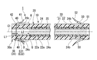
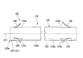
- the stent 1 (medical stent) according to this embodiment includes a main body 10 having a first rigid portion 20 and a second rigid portion 30, and a flap (locking member) 40.
- the first rigid portion 20 and the second rigid portion 30 have a flap 40 formed in a tubular shape along the longitudinal axis C ⁇ b> 1, and an extended portion 41 extending radially outward of the main body 10, and the extended portion 41.
- a base end portion 42 fixed to the second rigid portion 30.
- the first rigid portion 20 includes a first resin portion 21 formed in a tubular shape, and a coil (first reinforcement portion) 22 fixed to the first resin portion 21.
- the first resin portion 21 includes a distal end portion of the outer layer 24 formed in a tubular shape, and a distal end portion of the inner layer 25 that is formed in a tubular shape and is provided coaxially with the outer layer 24 on the inner peripheral side of the outer layer 24. Including.
- the outer layer 24 is formed of a resin material having elasticity, flexibility, and biocompatibility such as urethane and polyethylene.
- the outer layer 24 has an outer diameter of 3.2 mm (10 French) and a length of 100 mm.
- the outer layer 24 is provided not only on the outer peripheral surface side of the coil 22 but also in a gap between the strands 22 a described later of the coil 22.
- flaps 50 are formed at the end portion of the outer layer 24 that is the distal end side when inserted into the bile duct on the side opposite to the second rigid portion 30 (one flap 50). Is not shown.)
- the flap 50 is formed by cutting a part of the outer layer 24 in the longitudinal direction and raising the cut part. That is, the material of the flap 50 is the same as the material of the outer layer 24.
- the four flaps 50 are formed at equiangular intervals around the longitudinal axis C1.
- the flap 50 has a first end 51 fixed to the outer peripheral surface of the outer layer 24 opposite to the second rigid portion 30 (first end), and a second end 52 along the longitudinal axis C1.
- the outer layer 24 is formed so as to open to the outer side in the radial direction of the main body 10 while extending toward the central portion 24 a side.
- a notch 24b is formed on the outer peripheral surface of the outer layer 24 at a position corresponding to each flap 50.
- the inner layer 25 is made of a resin material having a smooth surface and biocompatibility, such as PTFE (polytetrafluoroethylene) or PFA (perfluoroalkoxyalkane).
- PTFE polytetrafluoroethylene
- PFA perfluoroalkoxyalkane
- the coil 22 is formed by winding a wire 22a around a longitudinal axis C1 in a spiral shape at a constant pitch.
- the coil 22 is formed in a tubular shape as a whole by winding one or more turns of the wire 22a.
- the strand 22a has radiopacity such as tungsten steel or stainless steel.
- the strand 22a is formed of a metal having a larger elastic modulus (tensile strength) than the outer layer 24 and the inner layer 25.
- the cross section orthogonal to the longitudinal direction of the strand 22a is formed in a circle.
- the outer diameter of the strand 22a is, for example, 0.11 mm.
- the pitch of the strands 22a in the direction along the longitudinal axis C1 is, for example, about 0.41 mm (the gap between the strands 22a is about 0.30 mm).
- the wire 22 a of the coil 22 is fixed (fixed) to the outer layer 24 and the inner layer 25.
- the coil 22 is provided coaxially with the first resin portion 21 at the boundary between the outer layer 24 and the inner layer 25. That is, the coil 22 is provided inside the first resin portion 21, for example, at a substantially intermediate portion in the radial direction. In the first rigid portion 20, the coil 22 is provided to maintain the tubular shape of the first resin portion 21.
- the first rigid portion 20 has a predetermined rigidity with respect to a compressive force in the radial direction.
- the rigidity mentioned here mainly means the proof strength against the force that crushes the stent in the radial direction.
- the second rigid portion 30 is formed in a tubular shape along the longitudinal axis C1.
- the 2nd rigid part 30 has the 2nd resin part 31 formed in the tubular shape with the resin material.
- the second resin portion 31 includes the base end portion of the outer layer 24 and the base end portion of the inner layer 25 described above.
- the second resin portion 31, that is, the second rigid portion 30 is connected to the base end portion of the first resin portion 21 substantially coaxially (including coaxial). Since the second rigid portion 30 does not include the coil 22, the second rigid portion 30 has rigidity lower than that of the first rigid portion 20.
- the second rigid portion 30 is connected to the first rigid portion 20 by being substantially coaxial with the proximal end portion of the first rigid portion 20 on the proximal end side of the first rigid portion 20.
- flaps 40 are formed at the end portion of the outer layer 24 that is the proximal end side when inserted into the bile duct on the side opposite to the first rigid portion 20 (one flap 40 is not shown). ).
- the flap 40 is formed by cutting up a part of the outer layer 24. That is, the material of the flap 40 is the same as the material of the outer layer 24.
- the four flaps 40 are formed at equiangular intervals around the longitudinal axis C1.
- the flap 40 has an extending part 41 and a base end part 42. As for the flap 40, the base end part 42 is being fixed to the outer peripheral surface of the 1st end 30a on the opposite side to the 1st rigid part 20 in the 2nd resin part 31.
- the flap 40 is formed such that the extending portion 41 extends toward the central portion 24a side of the outer layer 24 along the longitudinal axis C1 and opens outward in the radial direction of the main body 10.
- the base end portion 42 of the flap 40 is fixed to the second rigid portion 30 at an intermediate portion in the direction along the longitudinal axis C ⁇ b> 1 of the second rigid portion 30.
- the extending portion 41 is disposed at a substantially central position in the direction along the longitudinal axis C1 of the second rigid portion 30.
- the first length L1 from the first end 30a of the second rigid portion 30 opposite to the first rigid portion 20 to the base end portion 42 of the flap 40 is, for example, 5 mm.
- a notch 24c is formed on the outer peripheral surface of the outer layer 24 at a position corresponding to each flap 40.
- the flap 40 is shorter than the flap 50. By shortening the flap 40 on the proximal end side (duodenum side), it is possible to suppress the flap 40 from being caught by the forceps raising base at the endoscope exit, and to perform a smooth treatment.
- a boundary position Q that is a connection position between the first rigid portion 20 and the second rigid portion 30 is defined in the direction along the longitudinal axis C1.
- the boundary position Q is a portion where the proximal end of the coil 22 is located.
- the coil 22 is provided over the range from the boundary position Q to the end of the first rigid portion 20 opposite to the second rigid portion 30 without being provided on the second rigid portion 30 side from the boundary position Q. Yes.
- the second length L2 from the base end portion 42 of the flap 40 to the boundary position Q is, for example, 7 mm. That is, the first length L1 from the first end 30a of the second rigid portion 30 to the base end portion 42 of the flap 40 is equal to or less than the second length L2.
- the first length L1 is preferably shorter.
- the flap 40 is fixed to the outer layer 24 by heat welding or the like, it is preferable to secure the first length L1 of 4 mm or more in order to ensure the fixing strength.
- the second length L2 is more preferably set to 2 mm or more and 8 mm or less.
- the respective rigidity is substantially constant regardless of the position along the longitudinal axis C1. Since the rigidity of the second rigid portion 30 is large on the first rigid portion 20 side, the rigidity changes greatly at the boundary position Q.
- the main body 10 at a portion where the rigidity changes greatly is more likely to break because stress concentrates compared to other portions.
- a gripped region R a range from the central portion 24a side of the base end portion 42 of the flap 40 in the second rigid portion 30 to the boundary position Q.
- the operation of the stent 1 configured as described above will be described below by taking as an example a technique for placing the stent 1 in the bile duct and further replacing the placed stent 1.
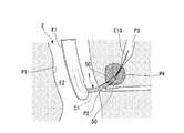
- a user such as an operator inserts a side-viewing type endoscope into a patient's body cavity through a natural opening such as a mouth, and the distal end of the insertion portion E1 of the endoscope E is inserted as shown in FIG. , Through the duodenum P1 to the vicinity of the duodenal papilla (tissue) P2.
- the user inserts the guide wire E10 into the channel E2 from the forceps opening (not shown) of the endoscope E, and appropriately operates the raising base (not shown), and the tip of the guide wire E10 is opened to the tip of the channel E2. Project toward the duodenal papilla P2. Then, the distal end of the guide wire E10 is inserted from the duodenal papilla P2 into the bile duct P3.
- the user confirms the shapes of the stenosis P4 of the duodenal papilla P2 and the bile duct P3 under X-ray fluoroscopy, and selects the stent 1 having a suitable length. That is, when each flap 40, 50 is opened, the length from the extension 41 of the flap 40 to the second end 52 of the flap 50 is the length from the duodenal papilla P2 to the position beyond the constriction P4 of the bile duct P3. A stent 1 having a thickness is selected.
- the user uses the stent delivery catheter (not shown) inserted from the forceps opening to place the stent 1 along the guide wire E10 from the flap 50 side to the bile duct P3. Insert inside.
- the flap 50 When the distal end of the stent 1 reaches the constriction P4 of the bile duct P3, the flap 50 is pressed toward the longitudinal axis C1 by the constriction P4, and the flap 50 is accommodated in the notch 24b.
- the stent 1 When the stent 1 is further inserted into the bile duct P3 and the flap 50 exceeds the constriction P4, the second end 52 side of the flap 50 is opened as shown in FIG. 4, and the flap 50 is locked to the constriction P4.
- the flap 40 is also locked to the duodenal papilla P2.
- the base end portion of the second rigid portion 30 protrudes from the duodenal papilla P2 into the lumen of the duodenum P1 and is placed.
- the outer peripheral surface of the main body 10 on the side of the central portion 24a slightly from the base end portion 42 of the flap 40 protrudes into the lumen of the duodenum P1 when indwelling.
- the 1st rigid part 20 is detained in the bile duct P3.
- the boundary position Q of the stent 1 is located in the vicinity of the duodenal papilla P2. That is, the 2nd rigid part 30 is located in the duodenum P1 substantially. Therefore, in the stent 1, the space in the duct that is pressed by the bile duct P ⁇ b> 3 or the like is held by the coil 22.
- the user removes the guide wire E10 and the insertion portion E1 of the endoscope E from the body cavity of the patient, and ends the procedure of placing the stent 1. Thereafter, when the stent 1 is placed for a certain period, the placed stent 1 is replaced with a new stent 1 as described below.
- the user inserts the distal end of the insertion portion E1 of the endoscope E through the duodenum P1 to the vicinity of the duodenal papilla P2 as described above.
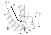
- the snare E20 is inserted into the channel E2 through the forceps opening.
- the snare E20 used at this time is selected such that the outer diameter D (see FIG. 2) of the wire E22 constituting the loop portion E21 of the snare E20 is sufficiently smaller than the second length L2.
- the loop portion E21 is configured by forming a wire E22 in a loop shape.
- the snare E20 is pushed into the forceps opening, and the loop portion E21 is protruded from the tip opening of the channel E2.
- the loop portion E21 is hung on the gripped region R of the stent 1 through the proximal end side of the stent 1 through the loop portion E21. More specifically, the loop portion E21 is hung on the outer peripheral surface of the main body 10 on the side of the central portion 24a slightly from the base end portion 42 of the flap 40.
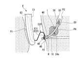
- the snare E20 When the snare E20 is pulled back with the position of the insertion portion E1 fixed, the loop portion E21 is locked to the central portion 24a side of the base end portion 42 of the flap 40 in the main body 10 as shown in FIGS. . Thereby, the stent 1 is hold
- the stent 1 When the snare E20 is pulled back, the stent 1 is pulled out from the bile duct P3 and, as shown in FIG. 6, the stent 1 is pulled into the channel E2 of the insertion portion E1.
- the grasped region R held by the stent 1 enters the channel E2 first, and the first rigid portion 30 of the second rigid portion 30 that is the distal end portion and the proximal end portion of the stent 1 relative to the grasped region R.
- One end 30a then enters channel E2. That is, the stent 1 is drawn into the channel E2 while being folded in the grasped region R. Since the outer diameter of the stent 1 as a whole is increased at the portion where the stent 1 is folded, as shown in FIG. 7, the stent 1 is crushed in the radial direction when it is drawn into the channel E2.
- the coil 22 Since the first length L1 is shorter than the second length L2, the coil 22 is not provided in any of the folded and overlapping portions of the stent 1. For this reason, the outer diameter of the overlapping portion is easily reduced. Since the wire E22 is separated from the boundary position Q, an excessive force does not act on the boundary position Q of the stent 1, for example, the wire E22 bites into the boundary position Q of the stent 1. When the folded and overlapped portion of the stent 1 passes through the channel E2, it passes through the channel E2 so that the remaining portion of the stent 1 is also interlocked.
- the snare E20 is pulled back, and the stent 1 and the snare E20 are pulled out of the body through the channel E2. Thereafter, the guide wire E10 is inserted into the channel E2 as described above, and the new stent 1 is placed in the bile duct P3 through the channel E2.
- the first rigid portion 20 is higher in rigidity than the second rigid portion 30, so that the space in the portion of the duct that is pressed by the bile duct P3 at the time of placement is maintained. Since the second rigid portion 30 is lower in rigidity than the first rigid portion 20, the second rigid portion 30 is a portion that is first drawn into the channel E 2 when the stent 1 is passed through the channel E 2 to recover the stent 1. It is possible to easily crush, that is, deform, the gripped region R that is a portion.
- the wire E22 of the snare E20 is separated from the boundary position Q when the loop portion E21 is locked to the proximal end portion 42 of the flap 40. Therefore, it is possible to suppress the excessive force from acting on the boundary position Q where the rigidity of the stent 1 greatly changes and the main body 10 being torn at the boundary position Q and breaking.
- the first length L1 from the first end 30a of the second rigid portion 30 to the base end portion 42 of the flap 40 is equal to or less than the second length L2 from the base end portion 42 of the flap 40 to the boundary position Q.
- the first length L1 from the first end 30a of the second rigid portion 30 to the base end portion 42 of the flap 40 is the second length from the base end portion 42 of the flap 40 to the boundary position Q. It may be longer than L2. This is because the second rigid portion 30 can be crushed and the outer diameter of the folded portion of the stent 1 can be suppressed even with such a configuration.
- the coil 22 is used as the first reinforcing portion.
- the first reinforcing portion is not limited to this, and a blade 60 may be used as the first reinforcing portion, for example, as in the stent 2 shown in FIG.
- a known blade having a configuration in which metal strands are knitted in a net shape can be used.
- the snare E20 is used to pull the stent out of the body.
- the grasped region R of the stent may be grasped using grasping forceps or the like, or the stent 40 may be pulled out by being hooked on the proximal end portion 42 of the flap 40.
- grasping forceps it is preferable to select a grasping piece that grasps the stent 1 having a width sufficiently smaller than the second length L2.
- the four flaps 40 are fixed to the proximal end side of the outer layer 24 of the stent 1.
- the number of the flaps 40 fixed to the outer layer 24 is not limited, and may be 1 to 3, or 5 or more.
- the four flaps 40 are formed at equiangular intervals around the longitudinal axis C1, but these flaps 40 are formed at equiangular intervals around the longitudinal axis C1. It does not have to be.
- the flap 40 is formed by raising a cut portion by making a cut.
- the flap 40 may be formed by fixing a member formed separately from the outer layer 24 to the outer layer 24 by heat welding or the like. The same applies to the flap 50.
- the stent 1 may be used by being placed in the pancreatic duct.
- the stent 101 (medical stent) according to this embodiment includes a main body 110 having a first rigid portion 120 and a second rigid portion 130, and a flap (locking member) 140.
- the main body 110 has a first rigid portion 120 and a second rigid portion 130 formed in a tubular shape along the longitudinal axis C101.
- the flap 140 includes an extending portion 141 that extends outward in the radial direction of the main body 110, and a base end portion 142 that is connected to the extending portion 141 and is fixed to the second rigid portion 130.
- the first rigid portion 120 has a first resin portion 121 and a coil (first reinforcing portion) 122.
- the first resin part 121 is formed in a tubular shape.
- the coil 122 is fixed to the first resin portion 121.
- the first resin portion 121 includes a distal end portion of the outer layer 124 formed in a tubular shape, and a distal end portion of the inner layer 125 that is formed in a tubular shape and is provided coaxially with the outer layer 124 on the inner peripheral side of the outer layer 124.
- the outer layer 124 is formed of a resin material having elasticity, flexibility, and biocompatibility such as urethane and polyethylene.
- the outer layer 124 has an outer diameter of 3.2 mm (10 French) and a length of 100 mm.
- the outer layer 124 is provided not only on the outer peripheral surface side of the coil 122 but also in a gap between the strands 122 a described later of the coil 122.
- three flaps 150 are formed at the end portion of the outer layer 124 that is the distal end side when inserted into the bile duct on the side opposite to the second rigid portion 130 (one flap 150 is Not shown).
- the flap 150 is formed by cutting a part of the outer layer 124 and raising the cut part. That is, the material of the flap 150 is the same as that of the outer layer 124.
- the three flaps 150 are formed at equiangular intervals around the longitudinal axis C101.
- the first end 151 of the flap 150 is fixed to the outer peripheral surface of the second end 120 a on the opposite side of the outer layer 124 from the second rigid portion 130.
- the flap 150 is formed such that the second end portion 152 extends toward the center portion 124 a side of the outer layer 124 along the longitudinal axis C ⁇ b> 101 and opens outward in the radial direction of the main body 110.
- a notch 124b is formed on the outer peripheral surface of the outer layer 124 at a position corresponding to each flap 150.
- the inner layer 125 is formed of a resin material having a smooth surface and biocompatibility, such as PTFE (polytetrafluoroethylene) and PFA (perfluoroalkoxyalkane).
- PTFE polytetrafluoroethylene
- PFA perfluoroalkoxyalkane
- the coil 122 is configured by winding a first strand (strand) 122a in a spiral shape around the longitudinal axis C101 at a constant pitch.
- the coil 122 is formed in a tubular shape as a whole by winding one or more turns of the first strand 122a.
- the first strand 122a has radiopacity such as tungsten steel and stainless steel.
- the first strand 122a is formed of a metal having a larger elastic modulus (tensile strength) than the outer layer 124 and the inner layer 125.
- the cross section orthogonal to the longitudinal direction of the first strand 122a is formed in a circular shape.
- the outer diameter of the first strand 122a is, for example, 0.11 mm.
- the pitch of the first strands 122a in the direction along the longitudinal axis C101 is, for example, about 0.41 mm (the gap between the first strands 122a is about 0.30 mm).
- the first strand 122 a of the coil 122 is fixed (fixed) to the outer layer 124 and the inner layer 125.
- the coil 122 is provided coaxially with the first resin portion 121 at a boundary portion between the outer layer 124 and the inner layer 125. That is, the coil 122 is provided inside the first resin portion 121, for example, at a substantially intermediate portion in the radial direction. In the first rigid portion 120, the coil 122 is provided to maintain the tubular shape of the first resin portion 121.
- the first rigid portion 120 has a predetermined rigidity with respect to a compressive force in the radial direction.
- the rigidity mentioned here mainly means the proof strength against the force that crushes the stent in the radial direction.
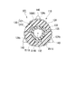
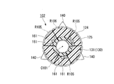
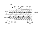
- the second rigid portion 130 is formed in a tubular shape along the longitudinal axis C101. As shown in FIGS. 10 and 11, the second rigid portion 130 includes a second resin portion 131 formed in a tubular shape with a resin material, and a reinforcing plate (second reinforcing portion) 132 fixed to the second resin portion 131. And have.
- the second resin portion 131 includes the base end portion of the outer layer 124 and the base end portion of the inner layer 125 described above.
- the base portion of the outer layer 124 and the base end portion of the inner layer 125 form a wall portion of the second resin portion 131.
- the second resin portion 131 that is, the second rigid portion 130 is connected to the base end portion of the first resin portion 121 substantially coaxially (including coaxial).
- Three flaps 140 are formed at the first end 130a on the opposite side of the first rigid portion 120 of the outer layer 124 which is the proximal end side when inserted into the bile duct (one flap 140 is not formed). Illustrated.) The flap 140 is formed by cutting a part of the outer layer 124 and raising the cut part. That is, the material of the flap 140 is the same as the material of the outer layer 124. The three flaps 140 are formed at equiangular intervals around the longitudinal axis C101.
- the flap 140 has an extended portion 141 and a proximal end portion 142.
- the base end part 142 is being fixed to the outer peripheral surface of the 1st end 130a on the opposite side to the 1st rigid part 120 in the 2nd resin part 131.
- FIG. The flap 140 is formed so that the extended portion 141 extends along the longitudinal axis C101 toward the central portion 124a of the outer layer 124 and opens radially outward of the main body 110.
- the base end portion 142 of the flap 140 is fixed to the second rigid portion 130 at an intermediate portion in the direction along the longitudinal axis C101 of the second rigid portion 130.
- the extending portion 141 is disposed at a substantially central position in the direction along the longitudinal axis C101 of the second rigid portion 130.
- the first length L101 from the first end 130a of the second rigid portion 130 opposite to the first rigid portion 120 to the base end portion 142 of the flap 140 is, for example, 5 mm.
- a notch 124c is formed on the outer peripheral surface of the outer layer 124 at a position corresponding to each flap 140.
- the flap 140 is shorter than the flap 150. By shortening the flap 140 on the proximal end side (duodenum side), it is possible to suppress the flap 140 from being caught by the forceps raising base at the exit of the endoscope and perform a smooth treatment.
- a boundary position Q100 that is a connection position between the first rigid portion 120 and the second rigid portion 130 is defined in the direction along the longitudinal axis C101.
- the boundary position Q100 is a portion where the proximal end of the coil 22 is located.
- the coil 122 extends in the direction along the longitudinal axis C101 from the boundary position Q100 of the first resin portion 121 to the end portion (second end) 120a of the first rigid portion 120 opposite to the second rigid portion 130.
- the first resin portion 121 is provided coaxially.
- the second length L102 from the base end 142 of the flap 140 to the boundary position Q100 is, for example, 7 mm.
- the first length L101 is preferably shorter.
- the flap 140 is fixed to the outer layer 124 by heat welding or the like, it is preferable to secure the first length L101 of 4 mm or more in order to ensure the fixing strength.
- the second length L102 is more preferably set to 2 mm or more and 8 mm or less.
- the reinforcing plate 132 is formed in a plate shape extending in the direction along the longitudinal axis C101.
- the reinforcing plate 132 is formed of a material having a larger elastic modulus than the outer layer 124 and the inner layer 125 such as hard urethane, nylon, and stainless steel.
- the stent 101 is provided with three reinforcing plates 132.
- Each reinforcing plate 132 is provided at a position that does not overlap the flap 140 in the circumferential direction of the main body 110 at an equal angle around the longitudinal axis C101 when viewed in the direction along the longitudinal axis C101.
- the reinforcing plate 132 is fixed so as not to be disposed between the flap 140 and the longitudinal axis C101.
- the reinforcing plates 132 are provided at intervals in the circumferential direction around the longitudinal axis C101 of the second resin portion 131.
- the reinforcing plate 132 is not provided in the region R101 that is a part of the second resin portion 131 in the circumferential direction, but is provided in the remaining portion that is a portion other than the region R101 in the circumferential direction of the second resin portion 131. ing.
- An outer layer 124 is provided between the reinforcing plates 132 adjacent in the circumferential direction.
- each reinforcing plate 132 is provided over a range from the first end 130a on the opposite side of the second rigid portion 130 to the boundary position Q100 in the direction along the longitudinal axis C101. ing.
- at least one of the three reinforcing plates 132 is connected to the coil 122 by bonding or welding.
- the second rigid portion 130 compresses the outer layer 124 between the reinforcing plates 132 adjacent to each other in the circumferential direction or pushes the outer layer 124 between the adjacent reinforcing plates 132. By doing so, the first rigid portion 120 has lower rigidity.
- the second rigid portion 130 is configured to be easily crushed in the radial direction as compared with the first rigid portion 120.
- a range from the central portion 124a side of the base end portion 142 of the flap 140 to the boundary position Q100 in the second rigid portion 130 is shown as a gripped region R100.
- the operation of the stent 101 configured as described above will be described as an example of a technique for placing the stent 101 in the bile duct and replacing the placed stent 101.
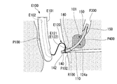
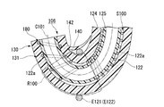
- a user such as an operator inserts a side-viewing type endoscope into a patient's body cavity through a natural opening such as a mouth, and inserts the distal end of the insertion portion E101 of the endoscope E as shown in FIG. And through the duodenum P101 to the vicinity of the duodenal papilla (tissue) P102.
- the user inserts the guide wire E110 into the channel E102 from a forceps opening (not shown) of the endoscope E100, and appropriately operates a raising base (not shown), and the tip of the guide wire E110 is opened to the tip of the channel E102. Project toward the duodenal papilla P102. Then, the distal end of the guide wire E110 is inserted from the duodenal papilla P102 into the bile duct P103.
- the user confirms the shapes of the stenosis P104 of the duodenal papilla P102 and the bile duct P103 under X-ray fluoroscopy, and selects the stent 101 having a suitable length. That is, the length from the extended portion 141 of the flap 140 to the second end portion 152 of the flap 150 when each of the flaps 140 and 150 is opened is the length from the duodenal papilla P102 to the position beyond the constricted portion P104 of the bile duct P103. A stent 101 having a thickness is selected.
- the user moves the stent 101 from the flap 150 side along the guide wire E110 by using a stent delivery catheter (not shown) inserted from the forceps opening. Insert inside.
- the flap 150 When the distal end of the stent 101 reaches the constriction P104 of the bile duct P103, the flap 150 is pressed toward the longitudinal axis C101 by the constriction P104, and the flap 150 is accommodated in the notch 124b.
- the stent 101 is further inserted into the bile duct P103 and the flap 150 exceeds the stenosis P104, the second end 152 side of the flap 150 is opened as shown in FIG. 13, and the flap 150 is locked to the stenosis P104.
- the flap 140 is also locked to the duodenal papilla P102.
- the base end portion of the second rigid portion 130 protrudes from the duodenal papilla P102 into the lumen of the duodenum P101 and is placed.
- the outer peripheral surface of the main body 110 on the side of the central portion 124a slightly from the base end portion 142 of the flap 140 protrudes into the lumen of the duodenum P101 when indwelling.
- the 1st rigid part 120 is detained in the bile duct P103.
- the boundary position Q100 of the stent 101 is located in the vicinity of the duodenal papilla P102. That is, the 2nd rigid part 130 is located in the duodenum P101 substantially. Accordingly, the space in the duct where the stent 101 is pressed by the bile duct P103 or the like is held by the coil 122.
- the user removes the guide wire E110 and the insertion portion E101 of the endoscope E100 from the body cavity of the patient, and ends the procedure of placing the stent 101. After this, when the stent 101 is placed for a certain period, the placed stent 101 is replaced with a new stent 101 as described below.
- the user inserts the distal end of the insertion portion E101 of the endoscope E100 through the duodenum P101 to the vicinity of the duodenal papilla P102.
- the snare E120 is inserted into the channel E102 through the forceps opening.
- the loop portion E121 of the snare E120 is configured by forming a wire E122 in a loop shape.
- the snare E120 is pushed into the forceps opening, and the loop portion E121 is protruded from the tip opening of the channel E102.
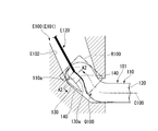
- the loop portion E121 is hung on the grasped region R100 of the stent 101 through the proximal end side of the stent 101 through the loop portion E121. More specifically, the loop portion E121 is hung on the outer peripheral surface of the main body 110 on the side of the central portion 124a slightly from the base end portion 142 of the flap 140.
- the stent 101 When the snare E120 is pulled back, the stent 101 is pulled out from the bile duct P103, and the stent 101 is pulled into the channel E102 of the insertion portion E101 as shown in FIG. At this time, the grasped region R100 held by the stent 101 enters the channel E102 first, and the second rigid portion 130 of the second rigid portion 130 that is the distal end portion and the proximal end portion of the stent 101 with respect to the grasped region R100. One end 130a then enters channel E102. That is, the stent 101 is drawn into the channel E102 while being folded in the gripped region R100.
- the flap 140 may be folded back toward the first end 130a of the second rigid portion 130.
- the region R101 of the second rigid portion 130 is easier to compress in the circumferential direction than the first rigid portion 120, the second rigid portion 130 can be easily crushed in the radial direction.
- the region R101 where the reinforcing plate 132 is not provided is more easily crushed in the radial direction than the region where the reinforcing plate 132 is provided.
- a recess 124e that is recessed toward the longitudinal axis C101 is formed on the outer peripheral surface of the outer layer 124 in the region R101.
- the second rigid portion 130 of the stent 101 When being pulled into the channel E102, the second rigid portion 130 of the stent 101 is stretched in the direction along the longitudinal axis C101.
- the second rigid portion 130 is provided with a reinforcing plate 132 made of a material having a larger elastic modulus than the outer layer 124 and the inner layer 125. For this reason, the rigidity in the direction along the longitudinal axis C101 of the 2nd rigid part 130 is large. Furthermore, since at least one of the three reinforcing plates 132 is connected to the coil 122, the rigidity of the connection portion between the second rigid portion 130 and the first rigid portion 120 is also large. Since the stent 101 has these configurations, it is suppressed that the second rigid portion 130 is torn in the direction along the longitudinal axis C101 when being pulled into the channel E102.
- the snare E120 is pulled back while the position of the insertion portion E101 is fixed, and the stent 101 and the snare E120 are pulled out of the body through the channel E102. Thereafter, the guide wire E110 is inserted into the channel E102 as described above, and the new stent 101 is placed in the bile duct P103 through the channel E102.
- the first rigid portion 120 is higher in rigidity than the second rigid portion 130, so that the space in the portion of the duct that is pressed by the bile duct P103 or the like at the time of placement is maintained. Since the second rigid portion 130 is lower in rigidity than the first rigid portion 120, the second rigid portion 130 is a portion that is first drawn into the channel E102 when the stent 101 is passed through the channel E102 in order to retrieve the stent 101. As compared with the first rigid portion 120, the gripped region R100 that is a portion can be easily crushed, that is, deformed.
- the second rigid portion 130 is provided with the reinforcing plate 132, the rigidity in the direction along the longitudinal axis C101 increases, and the second rigid portion 130 breaks when stretched in the direction along the longitudinal axis C101. Can be difficult.
- Each reinforcing plate 132 is provided at a position that does not overlap the flap 140 in the circumferential direction of the main body 110 when viewed in the direction along the longitudinal axis C101.
- a recess 124e is formed on the outer peripheral surface of the outer layer 124 in the region R101.
- the reinforcing plate 132 is formed in a plate shape extending in the direction along the longitudinal axis C101, the configuration of the reinforcing plate 132 becomes simple, and the reinforcing plate 132 can be easily formed. Since the reinforcing plate 132 is connected to the coil 122, the rigidity of the stent 101 at the boundary position Q100 can be increased.
- three flaps 140 are formed on the outer layer 124 of the stent 101, and three reinforcing plates 132 are provided on the second rigid portion 130.
- the number of the flaps 140 and the reinforcing plates 132 is not limited, and one or more flaps 140 may be formed on the outer layer 124, and one or more reinforcing plates 132 may be provided on the second rigid portion 130.
- the three flaps 140 are formed at equiangular intervals around the longitudinal axis C101, but these flaps 140 may not be formed at equiangular intervals around the longitudinal axis C101. .
- each reinforcing plate 132 is provided in a range from the opposite end of the second rigid portion 130 to the boundary position Q100 in the direction along the longitudinal axis C101.
- the reinforcing plate 132 may be provided over at least the gripped region R100. This is because even with this configuration, the rigidity of the portion of the stent 101 where the wire E122 of the snare E120 is locked can be increased.
- At least one of the three reinforcing plates 132 is connected to the coil 122, but all the reinforcing plates 132 may not be connected to the coil 122. In this case, the rigidity of the stent 101 at the boundary position Q100 is reduced.
- a snare E120 having a sufficiently smaller outer diameter D (see FIG. 10) of the wire E122 constituting the loop portion E121 than the above-described second length L102 is selected.
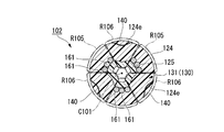
- the stent 102 (medical stent) according to this embodiment includes a plurality of rod-like bodies (second reinforcing portions) 161 instead of the reinforcing plate 132 of the stent 101 according to the second embodiment. Yes.
- Each rod-shaped body 161 is formed in a columnar shape (bar shape) extending in a direction along the longitudinal axis C101.
- the rod-shaped body 161 can be formed of the same material as the reinforcing plate 132.
- Each rod-like body 161 is provided in a region R105 that is a position that does not overlap the flap 140 in the circumferential direction of the second resin portion 131 when viewed in the direction along the longitudinal axis C101. That is, the rod-shaped body 161 is not disposed between the flap 140 and the longitudinal axis C101.
- the three rod-shaped bodies 161 are provided in the region R5 between the adjacent flaps 140 in the circumferential direction at intervals in the circumferential direction.
- An outer layer 124 is provided between the rod-shaped bodies 161 adjacent in the circumferential direction.
- the stent 102 configured in this manner is as shown in FIG. 19 when the loop portion E121 is locked to the grasped region R100 and the snare E120 is pulled back. That is, the region R106 of the second resin portion 131 in which the rod-shaped body 161 is not provided in the circumferential direction is more easily crushed in the radial direction than the region R105 in which the rod-shaped body 161 is provided, and the outer surface 124 of the outer layer 124 of the region R106 is A recess 124e is formed.
- the space in the pipe line can be maintained during detention, and can be easily crushed, that is, easily deformed, and not easily broken when pulled out.
- the rod-shaped body 161 is formed in a columnar shape extending in the direction along the longitudinal axis C101, the configuration of the rod-shaped body 161 becomes simple, and the rod-shaped body 161 can be easily formed. Since the three rod-shaped bodies 161 are provided in each region R105 at intervals in the circumferential direction, the three rod-shaped bodies 161 are easily crushed in the circumferential direction as a whole. Therefore, the second rigid portion 130 of the stent 102 can be crushed more easily.
- rods 161 are provided in each region R105.
- the number of rod-shaped bodies 161 provided in the region R105 is not limited, and may be two or four or more as long as it is plural.
- the stent 102 can be variously deformed as described below.
- a single rod-like body 161 may be provided as in the stent 103 (medical stent) of the modification shown in FIG. In FIG. 20, the flaps 140 and 150 are not shown.
- the rod-shaped body 161 is formed so as to extend in the direction along the longitudinal axis C ⁇ b> 101 and is connected to the coil 122.
- the coil 122 and the rod-shaped body 161 can be integrally formed by bending one strand, and the stent 103 can be easily manufactured.
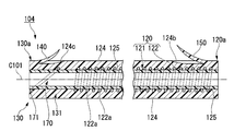
- the second reinforcing portion 170 may be formed in a shape in which the second strand 171 is spirally wound around the longitudinal axis C101. .
- the second reinforcing portion 170 is coaxial with the second resin portion 131 and is provided between the outer layer 124 and the inner layer 125, that is, in the intermediate portion in the radial direction of the second resin portion 131.
- the central angle ⁇ of the second reinforcing portion 170 is an angle smaller than 360 °, for example, 270 °.
- the coil 122 and the second reinforcing portion 170 are integrally formed by bending one strand.
- a region where the second reinforcing portion 170 is not provided in the circumferential direction is formed. It becomes easy to crush the 2nd rigid part 130.
- FIG. The stent 104 configured as described above can be easily manufactured by integrally forming the coil 122 and the second reinforcing portion 170.
- the coil 122 and the rod-shaped body 161 may be integrally formed by welding the coil 122 and the rod-shaped body 161 that are separately formed by processing the wire. The same applies to the modified stent 104.
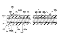
- the stent 105 (medical stent) according to the present embodiment includes a coil (second reinforcing portion) 180 instead of the three reinforcing plates 132 of the stent 101 according to the second embodiment. Yes.
- the coil 180 is configured by winding the above-described first strand 122a around the longitudinal axis C101 in a spiral shape at a constant pitch.
- the coil 180 is formed in a tubular shape as a whole by winding the first strand 122a one or more turns.
- the coil 180 and the coil 122 are integrally formed from the same first strand 122a, and are configured in a tubular shape as a whole.
- the coil 180 is provided coaxially with the second resin portion 131 at the boundary between the outer layer 124 and the inner layer 125.
- the first strand 122 a of the coil 180 is fixed (fixed) to the outer layer 124 and the inner layer 125.
- the coil 180 is provided to maintain the tubular shape of the second resin portion 131.
- the outer diameters of the coil 180 and the coil 122 are equal.
- the pitch L106 of the first strand 122a in the coil 180 is larger than the pitch L107 of the first strand 122a in the coil 122.
- the coil 180 is less rigid than the coil 122 by increasing the pitch L106 of the first strands 122a.
- the pitch L106 of the coil 180 is more preferably 1.1 to 5 times the pitch L107 of the coil 122.
- the space in the duct is mainly held by the coil 122.
- the loop portion E121 is locked to the grasped region R100.
- the coil 180 is less rigid than the coil 122, the stent 105 is more easily crushed in the radial direction in the second rigid portion 130 than in the first rigid portion 120.
- it is easy to be crushed, that is, to be deformed, when it is withdrawn while retaining the space in the duct during indwelling.
- the gripped region R100 which is a part of the second rigid portion 130, can be easily crushed, that is, deformed, in the radial direction as compared with the first rigid portion 120.
- the rigidity of the coil 180 may be made smaller than that of the coil 122 by making the outer diameter of the wire constituting the coil 180 smaller than that of the wire constituting the coil 122.
- the coil 122 and the coil 180 have the same outer diameter of the wire and the outer diameter of the coils 122 and 180 as a whole, and the coil 180 is configured based on the elastic modulus of the wire constituting the coil 122.
- the rigidity of the coil 180 may be made smaller than that of the coil 122 by reducing the elastic modulus of the wire.
- the stent 106 (medical stent) according to this embodiment is a boundary portion between the outer layer 124 and the inner layer 125 in the configuration of the stent 105 according to the fourth embodiment, and has a longitudinal axis.
- a gap S100 is formed from the base end portion 142 of the flap 140 to the central portion 124a of the outer layer 124 in the direction along C101.
- the 1st strand 122a is arrange
- the first strand 122a is provided so as to be movable in the direction along the longitudinal axis C101 with respect to the outer layer 124 and the inner layer 125.
- the first strands 122a disposed at positions other than the gap S100 are fixed to the outer layer 124 and the inner layer 125.
- the gap S100 is formed by thermally welding a range other than the gap S100 without thermally welding the outer layer 124 and the inner layer 125 in a range corresponding to the gap S100 in the direction along the longitudinal axis C101.
- the loop portion E121 of the snare E120 is hung on the grasped region R100 as illustrated in FIG.
- the outer layer 124 pressed by the wire E122 is deformed to the longitudinal axis C101 side, and the stent 106 is folded back in the grasped region R100.
- the first strand 122a located at the position of the wire E122 in the direction along the longitudinal axis C101 moves so as to be separated from the wire E122 within the gap S100.
- the movement of the first strand 122a within the gap S100 also occurs when the stent 106 is bent.
- the outer layer 124 and the inner layer 125 can be deformed without interlocking with the movement of the first strand 122a in the gap S100, the outer layer 124 and the inner layer 125 are not easily broken. This increases the buckling resistance of the stent 106.
- the stent 106 according to the present embodiment can be easily crushed, that is, easily deformed when pulled out while retaining the space in the duct during placement.
- the first strand 122a is provided so as to be movable in the direction along the longitudinal axis C101 within the gap S100 between the outer layer 124 and the inner layer 125. For this reason, the outer layer 124 and the inner layer 125 can be made difficult to break when the snare E120 is hung or bent on the gripped region R100.
- the gap S100 between the outer layer 124 and the inner layer 125 is formed from the base end portion 142 of the flap 140 to the central portion 124a of the outer layer 124 in the direction along the longitudinal axis C101.
- the gap S100 only needs to be formed from the base end 142 of the flap 140 to the boundary position Q100 in the direction along the longitudinal axis C101. This is because the first strand 122a can move in the direction along the longitudinal axis C101 within the gap S100 when the snare E120 is applied to the gripped region R100.
- the coil 122 is used as the first reinforcing portion.
- the first reinforcing portion is a blade 190 like a stent 107 (medical stent) shown in FIG. May be.
- the blade 190 has a known configuration in which metal strands are knitted in a net shape.
- the snare E120 is used to pull out the stent from the body.
- the stent may be pulled out by grasping the grasped region R100 of the stent using grasping forceps or the like instead of the snare E120, or by hooking on the proximal end portion 142 of the flap 140.
- three flaps 150 are provided in the outer layer 124 of the stent. However, these flaps 150 may not be provided in the stent.
- the flap 140 showed the example currently formed by cutting up. However, the flap 140 may be formed by fixing a member formed separately from the outer layer 124 to the outer layer 124 by heat welding or the like. The same applies to the flap 150.
- the stent in the second to fifth embodiments, the case where the stent is placed in the bile duct P103 has been described.
- the stent according to this embodiment may be used by being placed in the pancreatic duct.
- Stent (medical stent) 10 110: Main body 20, 120: First rigid portion 21, 121: First resin portion 22, 122: Coil (first reinforcing portion) 22a, 122a: First strand (strand) 24, 124: outer layers 24a, 124a: central portions 24b, 24c, 124b, 124c: notches 25, 125: inner layers 30, 130: second rigid portions 30a, 130a: first ends 31, 131: second Resin portions 32 and 132: Reinforcing plate (second reinforcing portion) 40,140: Flap (locking member) 50, 150: Flap 41, 141: Extension part 42, 142: Base end part 51, 151: First end part 52, 152: Second end part 60, 190: Blade (first reinforcing part) 161: Rod-shaped body (second reinforcing part) 170: 2nd reinforcement part 171: 2nd strand 180: Coil (2nd reinforcement part)
Abstract
L'invention concerne une endoprothèse médicale (1), qui comprend : un corps principal (10) qui comprend une première partie rigide (20) qui a une forme tubulaire le long d'un axe longitudinal et a une rigidité prédéterminée par rapport à une force de compression dans une direction radiale, et une seconde partie rigide (30) qui a une rigidité inférieure à celle de la première partie rigide (20), s'étend sensiblement coaxialement à partir d'une partie extrémité de base de la première partie rigide (20), et a une forme tubulaire le long de l'axe longitudinal ; et un élément de verrouillage (40) qui est agencé sur la seconde partie rigide (30) pour être verrouillé sur un tissu, et a une partie extrémité de base (42) qui s'étend à partir de la seconde partie rigide (30) et une partie extension (41) qui s'étend à partir de la partie extrémité de base (42) dans une direction radialement vers l'extérieur du corps principal (10), dans une position sensiblement centrale de la seconde partie rigide (30) dans la direction le long de l'axe longitudinal.
Priority Applications (5)
| Application Number | Priority Date | Filing Date | Title |
|---|---|---|---|
| CN201380033978.1A CN104507422B (zh) | 2013-03-07 | 2013-12-03 | 医疗用支架 |
| JP2014530844A JP5642909B1 (ja) | 2013-03-07 | 2013-12-03 | 医療用ステント |
| EP13877309.8A EP2965723A4 (fr) | 2013-03-07 | 2013-12-03 | Endoprothèse médicale |
| US14/318,053 US9585772B2 (en) | 2013-03-07 | 2014-06-27 | Stent for medical use |
| US15/416,280 US10383719B2 (en) | 2013-03-07 | 2017-01-26 | Stent for medical use |
Applications Claiming Priority (4)
| Application Number | Priority Date | Filing Date | Title |
|---|---|---|---|
| US201361774290P | 2013-03-07 | 2013-03-07 | |
| US201361774302P | 2013-03-07 | 2013-03-07 | |
| US61/774,290 | 2013-03-07 | ||
| US61/774,302 | 2013-03-07 |
Related Child Applications (1)
| Application Number | Title | Priority Date | Filing Date |
|---|---|---|---|
| US14/318,053 Continuation US9585772B2 (en) | 2013-03-07 | 2014-06-27 | Stent for medical use |
Publications (1)
| Publication Number | Publication Date |
|---|---|
| WO2014136334A1 true WO2014136334A1 (fr) | 2014-09-12 |
Family
ID=51490877
Family Applications (1)
| Application Number | Title | Priority Date | Filing Date |
|---|---|---|---|
| PCT/JP2013/082440 WO2014136334A1 (fr) | 2013-03-07 | 2013-12-03 | Endoprothèse médicale |
Country Status (5)
| Country | Link |
|---|---|
| US (2) | US9585772B2 (fr) |
| EP (1) | EP2965723A4 (fr) |
| JP (1) | JP5642909B1 (fr) |
| CN (1) | CN104507422B (fr) |
| WO (1) | WO2014136334A1 (fr) |
Cited By (2)
| Publication number | Priority date | Publication date | Assignee | Title |
|---|---|---|---|---|
| KR101904646B1 (ko) | 2017-02-21 | 2018-10-04 | 인제대학교 산학협력단 | 뇌척수액 운송용 도관의 이탈 방지 장치 |
| DE112018008164T5 (de) | 2018-11-22 | 2021-08-12 | Olympus Corporation | Medizinischer Stent und Stent-Zuführeinrichtung |
Families Citing this family (4)
| Publication number | Priority date | Publication date | Assignee | Title |
|---|---|---|---|---|
| US11207199B2 (en) | 2008-06-11 | 2021-12-28 | Q3 Medical Devices Limited | Stent with anti-migration devices |
| CN110769786B (zh) * | 2017-06-13 | 2022-12-09 | 株式会社钟化 | 生物体内留置管 |
| US10881275B2 (en) | 2018-08-03 | 2021-01-05 | Olympus Corporation | Medical device insertion method |
| CN113924067A (zh) * | 2019-03-19 | 2022-01-11 | Q3医疗设备有限公司 | 带有防移动装置的支架 |
Citations (6)
| Publication number | Priority date | Publication date | Assignee | Title |
|---|---|---|---|---|
| JPH05192389A (ja) * | 1991-10-16 | 1993-08-03 | Olympus Optical Co Ltd | 生体内留置チューブ |
| JPH1176412A (ja) | 1997-09-12 | 1999-03-23 | Olympus Optical Co Ltd | ドレナージチューブ |
| JP2007524480A (ja) * | 2004-01-28 | 2007-08-30 | アプライド メディカル リソーシーズ コーポレイション | 可変特性を有する医療管材とその製造方法 |
| JP2010536430A (ja) * | 2007-08-15 | 2010-12-02 | ウィルソン−クック・メディカル・インコーポレーテッド | ソフトステント用展開システム |
| JP2010537743A (ja) * | 2007-08-31 | 2010-12-09 | ウィルソン−クック・メディカル・インコーポレーテッド | 改良された薬物溶出要素を有する医用インプラント |
| JP4981994B2 (ja) | 2010-03-26 | 2012-07-25 | オリンパスメディカルシステムズ株式会社 | 医療用ステント |
Family Cites Families (13)
| Publication number | Priority date | Publication date | Assignee | Title |
|---|---|---|---|---|
| US5282860A (en) * | 1991-10-16 | 1994-02-01 | Olympus Optical Co., Ltd. | Stent tube for medical use |
| JP2002537065A (ja) * | 1999-02-26 | 2002-11-05 | ヴァスキュラー・アーキテクツ・インコーポレイテッド | 管腔内プロステーゼを備えるカテーテルアセンブリとその設置方法 |
| JP4043210B2 (ja) * | 2001-10-09 | 2008-02-06 | オリンパス株式会社 | ステント |
| CN200960355Y (zh) * | 2006-09-21 | 2007-10-17 | 中国人民解放军第二军医大学 | 一种可承载微型放射性粒子源的管道支架 |
| US9107741B2 (en) * | 2007-11-01 | 2015-08-18 | Cook Medical Technologies Llc | Flexible stent graft |
| CN201246551Y (zh) * | 2008-08-29 | 2009-05-27 | 镇江飞达医疗器材有限公司 | 医用高分子管材 |
| KR20100042478A (ko) * | 2008-10-16 | 2010-04-26 | (주) 태웅메디칼 | 굴곡 변형성을 갖는 스텐트의 제조방법과 그 스텐트 |
| CN102202605A (zh) * | 2008-10-22 | 2011-09-28 | 威尔逊-库克医学公司 | 预防胰腺病症的支架 |
| EP2564818B1 (fr) | 2010-10-29 | 2015-05-13 | Olympus Medical Systems Corp. | Endoprothèse médicale |
| EP2640325B1 (fr) * | 2010-11-19 | 2016-07-20 | Boston Scientific Scimed, Inc. | Système de mise en place d'une endoprothèse à échange rapide |
| JP5769992B2 (ja) * | 2011-03-23 | 2015-08-26 | 株式会社グッドマン | カテーテル |
| US8870947B2 (en) * | 2011-09-16 | 2014-10-28 | W.L. Gore & Associates, Inc. | Medical device fixation anchors |
| US8968386B2 (en) * | 2012-07-11 | 2015-03-03 | The Cleveland Clinic Foundation | Stent and method for maintaining the area of a body lumen |
-
2013
- 2013-12-03 CN CN201380033978.1A patent/CN104507422B/zh active Active
- 2013-12-03 EP EP13877309.8A patent/EP2965723A4/fr active Pending
- 2013-12-03 JP JP2014530844A patent/JP5642909B1/ja active Active
- 2013-12-03 WO PCT/JP2013/082440 patent/WO2014136334A1/fr active Application Filing
-
2014
- 2014-06-27 US US14/318,053 patent/US9585772B2/en active Active
-
2017
- 2017-01-26 US US15/416,280 patent/US10383719B2/en active Active
Patent Citations (6)
| Publication number | Priority date | Publication date | Assignee | Title |
|---|---|---|---|---|
| JPH05192389A (ja) * | 1991-10-16 | 1993-08-03 | Olympus Optical Co Ltd | 生体内留置チューブ |
| JPH1176412A (ja) | 1997-09-12 | 1999-03-23 | Olympus Optical Co Ltd | ドレナージチューブ |
| JP2007524480A (ja) * | 2004-01-28 | 2007-08-30 | アプライド メディカル リソーシーズ コーポレイション | 可変特性を有する医療管材とその製造方法 |
| JP2010536430A (ja) * | 2007-08-15 | 2010-12-02 | ウィルソン−クック・メディカル・インコーポレーテッド | ソフトステント用展開システム |
| JP2010537743A (ja) * | 2007-08-31 | 2010-12-09 | ウィルソン−クック・メディカル・インコーポレーテッド | 改良された薬物溶出要素を有する医用インプラント |
| JP4981994B2 (ja) | 2010-03-26 | 2012-07-25 | オリンパスメディカルシステムズ株式会社 | 医療用ステント |
Non-Patent Citations (1)
| Title |
|---|
| See also references of EP2965723A4 |
Cited By (2)
| Publication number | Priority date | Publication date | Assignee | Title |
|---|---|---|---|---|
| KR101904646B1 (ko) | 2017-02-21 | 2018-10-04 | 인제대학교 산학협력단 | 뇌척수액 운송용 도관의 이탈 방지 장치 |
| DE112018008164T5 (de) | 2018-11-22 | 2021-08-12 | Olympus Corporation | Medizinischer Stent und Stent-Zuführeinrichtung |
Also Published As
| Publication number | Publication date |
|---|---|
| US9585772B2 (en) | 2017-03-07 |
| US10383719B2 (en) | 2019-08-20 |
| EP2965723A1 (fr) | 2016-01-13 |
| JP5642909B1 (ja) | 2014-12-17 |
| CN104507422A (zh) | 2015-04-08 |
| CN104507422B (zh) | 2016-08-24 |
| EP2965723A4 (fr) | 2016-12-21 |
| US20170128188A1 (en) | 2017-05-11 |
| JPWO2014136334A1 (ja) | 2017-02-09 |
| US20150005894A1 (en) | 2015-01-01 |
Similar Documents
| Publication | Publication Date | Title |
|---|---|---|
| JP5642909B1 (ja) | 医療用ステント | |
| EP3302311B1 (fr) | Dispositifs de traitement intravasculaire flexibles | |
| US8034094B2 (en) | Stent delivery system and stent delivery method | |
| US20060293696A1 (en) | Retrieval catheter | |
| KR101961530B1 (ko) | 임플란트용 삽입 및 릴리스 시스템 | |
| CN210170107U (zh) | 植入物、植入物输送系统及其医疗组件 | |
| EP4096539A1 (fr) | Appareil et procédé pour intervention neurovasculaire endoluminale | |
| CN111757708B (zh) | 与栓塞材料一起使用的输送装置 | |
| CN110636805B (zh) | 从血管内腔取出材料 | |
| US20220265293A1 (en) | Apparatus, system, and method for vasculature obstruction removal | |
| JP6995219B2 (ja) | 医療用ステントおよびステントデリバリー装置 | |
| US11172946B2 (en) | Apparatus, system, and method for vasculature obstruction removal | |
| EP3498234A1 (fr) | Panier de chargement pour système de mise en place d'endoprothèse | |
| US20190307587A1 (en) | Structure for a catheter sleeve and catheter sleeve | |
| WO2021124786A1 (fr) | Dispositif medical de transport de corps tubulaire | |
| JP2024002181A (ja) | デリバリーカテーテル | |
| IE20060306A1 (en) | A retrieval catheter |
Legal Events
| Date | Code | Title | Description |
|---|---|---|---|
| ENP | Entry into the national phase |
Ref document number: 2014530844 Country of ref document: JP Kind code of ref document: A |
|
| 121 | Ep: the epo has been informed by wipo that ep was designated in this application |
Ref document number: 13877309 Country of ref document: EP Kind code of ref document: A1 |
|
| NENP | Non-entry into the national phase |
Ref country code: DE |
|
| WWE | Wipo information: entry into national phase |
Ref document number: 2013877309 Country of ref document: EP |