WO2014136334A1 - Medical stent - Google Patents
Medical stent Download PDFInfo
- Publication number
- WO2014136334A1 WO2014136334A1 PCT/JP2013/082440 JP2013082440W WO2014136334A1 WO 2014136334 A1 WO2014136334 A1 WO 2014136334A1 JP 2013082440 W JP2013082440 W JP 2013082440W WO 2014136334 A1 WO2014136334 A1 WO 2014136334A1
- Authority
- WO
- WIPO (PCT)
- Prior art keywords
- resin
- stent
- longitudinal axis
- rigid
- reinforcing
- Prior art date
Links
- 239000011347 resin Substances 0.000 claims description 123
- 229920005989 resin Polymers 0.000 claims description 123
- 230000003014 reinforcing effect Effects 0.000 claims description 110
- 210000000013 bile duct Anatomy 0.000 claims description 41
- 239000000463 material Substances 0.000 claims description 34
- 230000002183 duodenal effect Effects 0.000 claims description 29
- 238000004804 winding Methods 0.000 claims description 11
- 210000000277 pancreatic duct Anatomy 0.000 claims description 8
- 230000002093 peripheral effect Effects 0.000 description 25
- 238000000034 method Methods 0.000 description 24
- 239000004106 carminic acid Substances 0.000 description 20
- 239000004149 tartrazine Substances 0.000 description 20
- 210000001198 duodenum Anatomy 0.000 description 13
- 238000003780 insertion Methods 0.000 description 13
- 230000037431 insertion Effects 0.000 description 13
- 239000001679 citrus red 2 Substances 0.000 description 12
- 208000031481 Pathologic Constriction Diseases 0.000 description 11
- 208000037804 stenosis Diseases 0.000 description 11
- 230000036262 stenosis Effects 0.000 description 11
- 238000003466 welding Methods 0.000 description 10
- 239000004176 azorubin Substances 0.000 description 7
- 230000002787 reinforcement Effects 0.000 description 7
- 238000012986 modification Methods 0.000 description 6
- 230000004048 modification Effects 0.000 description 6
- 239000002151 riboflavin Substances 0.000 description 6
- 239000004173 sunset yellow FCF Substances 0.000 description 6
- 239000004813 Perfluoroalkoxy alkane Substances 0.000 description 4
- 229910052751 metal Inorganic materials 0.000 description 4
- 239000002184 metal Substances 0.000 description 4
- 229920011301 perfluoro alkoxyl alkane Polymers 0.000 description 4
- -1 polyethylene Polymers 0.000 description 4
- 229920001343 polytetrafluoroethylene Polymers 0.000 description 4
- 239000004810 polytetrafluoroethylene Substances 0.000 description 4
- JOYRKODLDBILNP-UHFFFAOYSA-N Ethyl urethane Chemical compound CCOC(N)=O JOYRKODLDBILNP-UHFFFAOYSA-N 0.000 description 3
- 239000004148 curcumin Substances 0.000 description 3
- 238000002594 fluoroscopy Methods 0.000 description 3
- 229910001220 stainless steel Inorganic materials 0.000 description 3
- 239000010935 stainless steel Substances 0.000 description 3
- 239000004698 Polyethylene Substances 0.000 description 2
- 229910000831 Steel Inorganic materials 0.000 description 2
- 238000005452 bending Methods 0.000 description 2
- 210000000941 bile Anatomy 0.000 description 2
- 229920000573 polyethylene Polymers 0.000 description 2
- 230000000717 retained effect Effects 0.000 description 2
- 238000004904 shortening Methods 0.000 description 2
- 239000010959 steel Substances 0.000 description 2
- WFKWXMTUELFFGS-UHFFFAOYSA-N tungsten Chemical compound [W] WFKWXMTUELFFGS-UHFFFAOYSA-N 0.000 description 2
- 229910052721 tungsten Inorganic materials 0.000 description 2
- 239000010937 tungsten Substances 0.000 description 2
- 239000004677 Nylon Substances 0.000 description 1
- 239000012141 concentrate Substances 0.000 description 1
- 239000000470 constituent Substances 0.000 description 1
- 229920001778 nylon Polymers 0.000 description 1
- 239000012466 permeate Substances 0.000 description 1
- 238000011084 recovery Methods 0.000 description 1
Images


Classifications
-
- A—HUMAN NECESSITIES
- A61—MEDICAL OR VETERINARY SCIENCE; HYGIENE
- A61F—FILTERS IMPLANTABLE INTO BLOOD VESSELS; PROSTHESES; DEVICES PROVIDING PATENCY TO, OR PREVENTING COLLAPSING OF, TUBULAR STRUCTURES OF THE BODY, e.g. STENTS; ORTHOPAEDIC, NURSING OR CONTRACEPTIVE DEVICES; FOMENTATION; TREATMENT OR PROTECTION OF EYES OR EARS; BANDAGES, DRESSINGS OR ABSORBENT PADS; FIRST-AID KITS
- A61F2/00—Filters implantable into blood vessels; Prostheses, i.e. artificial substitutes or replacements for parts of the body; Appliances for connecting them with the body; Devices providing patency to, or preventing collapsing of, tubular structures of the body, e.g. stents
- A61F2/02—Prostheses implantable into the body
- A61F2/04—Hollow or tubular parts of organs, e.g. bladders, tracheae, bronchi or bile ducts
-
- A—HUMAN NECESSITIES
- A61—MEDICAL OR VETERINARY SCIENCE; HYGIENE
- A61F—FILTERS IMPLANTABLE INTO BLOOD VESSELS; PROSTHESES; DEVICES PROVIDING PATENCY TO, OR PREVENTING COLLAPSING OF, TUBULAR STRUCTURES OF THE BODY, e.g. STENTS; ORTHOPAEDIC, NURSING OR CONTRACEPTIVE DEVICES; FOMENTATION; TREATMENT OR PROTECTION OF EYES OR EARS; BANDAGES, DRESSINGS OR ABSORBENT PADS; FIRST-AID KITS
- A61F2/00—Filters implantable into blood vessels; Prostheses, i.e. artificial substitutes or replacements for parts of the body; Appliances for connecting them with the body; Devices providing patency to, or preventing collapsing of, tubular structures of the body, e.g. stents
- A61F2/82—Devices providing patency to, or preventing collapsing of, tubular structures of the body, e.g. stents
- A61F2/848—Devices providing patency to, or preventing collapsing of, tubular structures of the body, e.g. stents having means for fixation to the vessel wall, e.g. barbs
-
- A—HUMAN NECESSITIES
- A61—MEDICAL OR VETERINARY SCIENCE; HYGIENE
- A61F—FILTERS IMPLANTABLE INTO BLOOD VESSELS; PROSTHESES; DEVICES PROVIDING PATENCY TO, OR PREVENTING COLLAPSING OF, TUBULAR STRUCTURES OF THE BODY, e.g. STENTS; ORTHOPAEDIC, NURSING OR CONTRACEPTIVE DEVICES; FOMENTATION; TREATMENT OR PROTECTION OF EYES OR EARS; BANDAGES, DRESSINGS OR ABSORBENT PADS; FIRST-AID KITS
- A61F2/00—Filters implantable into blood vessels; Prostheses, i.e. artificial substitutes or replacements for parts of the body; Appliances for connecting them with the body; Devices providing patency to, or preventing collapsing of, tubular structures of the body, e.g. stents
- A61F2/82—Devices providing patency to, or preventing collapsing of, tubular structures of the body, e.g. stents
- A61F2/94—Stents retaining their form, i.e. not being deformable, after placement in the predetermined place
-
- A—HUMAN NECESSITIES
- A61—MEDICAL OR VETERINARY SCIENCE; HYGIENE
- A61F—FILTERS IMPLANTABLE INTO BLOOD VESSELS; PROSTHESES; DEVICES PROVIDING PATENCY TO, OR PREVENTING COLLAPSING OF, TUBULAR STRUCTURES OF THE BODY, e.g. STENTS; ORTHOPAEDIC, NURSING OR CONTRACEPTIVE DEVICES; FOMENTATION; TREATMENT OR PROTECTION OF EYES OR EARS; BANDAGES, DRESSINGS OR ABSORBENT PADS; FIRST-AID KITS
- A61F2/00—Filters implantable into blood vessels; Prostheses, i.e. artificial substitutes or replacements for parts of the body; Appliances for connecting them with the body; Devices providing patency to, or preventing collapsing of, tubular structures of the body, e.g. stents
- A61F2/95—Instruments specially adapted for placement or removal of stents or stent-grafts
-
- A—HUMAN NECESSITIES
- A61—MEDICAL OR VETERINARY SCIENCE; HYGIENE
- A61F—FILTERS IMPLANTABLE INTO BLOOD VESSELS; PROSTHESES; DEVICES PROVIDING PATENCY TO, OR PREVENTING COLLAPSING OF, TUBULAR STRUCTURES OF THE BODY, e.g. STENTS; ORTHOPAEDIC, NURSING OR CONTRACEPTIVE DEVICES; FOMENTATION; TREATMENT OR PROTECTION OF EYES OR EARS; BANDAGES, DRESSINGS OR ABSORBENT PADS; FIRST-AID KITS
- A61F2/00—Filters implantable into blood vessels; Prostheses, i.e. artificial substitutes or replacements for parts of the body; Appliances for connecting them with the body; Devices providing patency to, or preventing collapsing of, tubular structures of the body, e.g. stents
- A61F2/02—Prostheses implantable into the body
- A61F2/04—Hollow or tubular parts of organs, e.g. bladders, tracheae, bronchi or bile ducts
- A61F2002/041—Bile ducts
-
- A—HUMAN NECESSITIES
- A61—MEDICAL OR VETERINARY SCIENCE; HYGIENE
- A61F—FILTERS IMPLANTABLE INTO BLOOD VESSELS; PROSTHESES; DEVICES PROVIDING PATENCY TO, OR PREVENTING COLLAPSING OF, TUBULAR STRUCTURES OF THE BODY, e.g. STENTS; ORTHOPAEDIC, NURSING OR CONTRACEPTIVE DEVICES; FOMENTATION; TREATMENT OR PROTECTION OF EYES OR EARS; BANDAGES, DRESSINGS OR ABSORBENT PADS; FIRST-AID KITS
- A61F2/00—Filters implantable into blood vessels; Prostheses, i.e. artificial substitutes or replacements for parts of the body; Appliances for connecting them with the body; Devices providing patency to, or preventing collapsing of, tubular structures of the body, e.g. stents
- A61F2/82—Devices providing patency to, or preventing collapsing of, tubular structures of the body, e.g. stents
- A61F2/848—Devices providing patency to, or preventing collapsing of, tubular structures of the body, e.g. stents having means for fixation to the vessel wall, e.g. barbs
- A61F2002/8483—Barbs
-
- A—HUMAN NECESSITIES
- A61—MEDICAL OR VETERINARY SCIENCE; HYGIENE
- A61F—FILTERS IMPLANTABLE INTO BLOOD VESSELS; PROSTHESES; DEVICES PROVIDING PATENCY TO, OR PREVENTING COLLAPSING OF, TUBULAR STRUCTURES OF THE BODY, e.g. STENTS; ORTHOPAEDIC, NURSING OR CONTRACEPTIVE DEVICES; FOMENTATION; TREATMENT OR PROTECTION OF EYES OR EARS; BANDAGES, DRESSINGS OR ABSORBENT PADS; FIRST-AID KITS
- A61F2/00—Filters implantable into blood vessels; Prostheses, i.e. artificial substitutes or replacements for parts of the body; Appliances for connecting them with the body; Devices providing patency to, or preventing collapsing of, tubular structures of the body, e.g. stents
- A61F2/82—Devices providing patency to, or preventing collapsing of, tubular structures of the body, e.g. stents
- A61F2/848—Devices providing patency to, or preventing collapsing of, tubular structures of the body, e.g. stents having means for fixation to the vessel wall, e.g. barbs
- A61F2002/8486—Devices providing patency to, or preventing collapsing of, tubular structures of the body, e.g. stents having means for fixation to the vessel wall, e.g. barbs provided on at least one of the ends
-
- A—HUMAN NECESSITIES
- A61—MEDICAL OR VETERINARY SCIENCE; HYGIENE
- A61F—FILTERS IMPLANTABLE INTO BLOOD VESSELS; PROSTHESES; DEVICES PROVIDING PATENCY TO, OR PREVENTING COLLAPSING OF, TUBULAR STRUCTURES OF THE BODY, e.g. STENTS; ORTHOPAEDIC, NURSING OR CONTRACEPTIVE DEVICES; FOMENTATION; TREATMENT OR PROTECTION OF EYES OR EARS; BANDAGES, DRESSINGS OR ABSORBENT PADS; FIRST-AID KITS
- A61F2/00—Filters implantable into blood vessels; Prostheses, i.e. artificial substitutes or replacements for parts of the body; Appliances for connecting them with the body; Devices providing patency to, or preventing collapsing of, tubular structures of the body, e.g. stents
- A61F2/95—Instruments specially adapted for placement or removal of stents or stent-grafts
- A61F2002/9528—Instruments specially adapted for placement or removal of stents or stent-grafts for retrieval of stents
-
- A—HUMAN NECESSITIES
- A61—MEDICAL OR VETERINARY SCIENCE; HYGIENE
- A61F—FILTERS IMPLANTABLE INTO BLOOD VESSELS; PROSTHESES; DEVICES PROVIDING PATENCY TO, OR PREVENTING COLLAPSING OF, TUBULAR STRUCTURES OF THE BODY, e.g. STENTS; ORTHOPAEDIC, NURSING OR CONTRACEPTIVE DEVICES; FOMENTATION; TREATMENT OR PROTECTION OF EYES OR EARS; BANDAGES, DRESSINGS OR ABSORBENT PADS; FIRST-AID KITS
- A61F2210/00—Particular material properties of prostheses classified in groups A61F2/00 - A61F2/26 or A61F2/82 or A61F9/00 or A61F11/00 or subgroups thereof
- A61F2210/0076—Particular material properties of prostheses classified in groups A61F2/00 - A61F2/26 or A61F2/82 or A61F9/00 or A61F11/00 or subgroups thereof multilayered, e.g. laminated structures
-
- A—HUMAN NECESSITIES
- A61—MEDICAL OR VETERINARY SCIENCE; HYGIENE
- A61F—FILTERS IMPLANTABLE INTO BLOOD VESSELS; PROSTHESES; DEVICES PROVIDING PATENCY TO, OR PREVENTING COLLAPSING OF, TUBULAR STRUCTURES OF THE BODY, e.g. STENTS; ORTHOPAEDIC, NURSING OR CONTRACEPTIVE DEVICES; FOMENTATION; TREATMENT OR PROTECTION OF EYES OR EARS; BANDAGES, DRESSINGS OR ABSORBENT PADS; FIRST-AID KITS
- A61F2220/00—Fixations or connections for prostheses classified in groups A61F2/00 - A61F2/26 or A61F2/82 or A61F9/00 or A61F11/00 or subgroups thereof
- A61F2220/0008—Fixation appliances for connecting prostheses to the body
- A61F2220/0016—Fixation appliances for connecting prostheses to the body with sharp anchoring protrusions, e.g. barbs, pins, spikes
-
- A—HUMAN NECESSITIES
- A61—MEDICAL OR VETERINARY SCIENCE; HYGIENE
- A61F—FILTERS IMPLANTABLE INTO BLOOD VESSELS; PROSTHESES; DEVICES PROVIDING PATENCY TO, OR PREVENTING COLLAPSING OF, TUBULAR STRUCTURES OF THE BODY, e.g. STENTS; ORTHOPAEDIC, NURSING OR CONTRACEPTIVE DEVICES; FOMENTATION; TREATMENT OR PROTECTION OF EYES OR EARS; BANDAGES, DRESSINGS OR ABSORBENT PADS; FIRST-AID KITS
- A61F2250/00—Special features of prostheses classified in groups A61F2/00 - A61F2/26 or A61F2/82 or A61F9/00 or A61F11/00 or subgroups thereof
- A61F2250/0014—Special features of prostheses classified in groups A61F2/00 - A61F2/26 or A61F2/82 or A61F9/00 or A61F11/00 or subgroups thereof having different values of a given property or geometrical feature, e.g. mechanical property or material property, at different locations within the same prosthesis
- A61F2250/0018—Special features of prostheses classified in groups A61F2/00 - A61F2/26 or A61F2/82 or A61F9/00 or A61F11/00 or subgroups thereof having different values of a given property or geometrical feature, e.g. mechanical property or material property, at different locations within the same prosthesis differing in elasticity, stiffness or compressibility
-
- A—HUMAN NECESSITIES
- A61—MEDICAL OR VETERINARY SCIENCE; HYGIENE
- A61F—FILTERS IMPLANTABLE INTO BLOOD VESSELS; PROSTHESES; DEVICES PROVIDING PATENCY TO, OR PREVENTING COLLAPSING OF, TUBULAR STRUCTURES OF THE BODY, e.g. STENTS; ORTHOPAEDIC, NURSING OR CONTRACEPTIVE DEVICES; FOMENTATION; TREATMENT OR PROTECTION OF EYES OR EARS; BANDAGES, DRESSINGS OR ABSORBENT PADS; FIRST-AID KITS
- A61F2250/00—Special features of prostheses classified in groups A61F2/00 - A61F2/26 or A61F2/82 or A61F9/00 or A61F11/00 or subgroups thereof
- A61F2250/0014—Special features of prostheses classified in groups A61F2/00 - A61F2/26 or A61F2/82 or A61F9/00 or A61F11/00 or subgroups thereof having different values of a given property or geometrical feature, e.g. mechanical property or material property, at different locations within the same prosthesis
- A61F2250/0029—Special features of prostheses classified in groups A61F2/00 - A61F2/26 or A61F2/82 or A61F9/00 or A61F11/00 or subgroups thereof having different values of a given property or geometrical feature, e.g. mechanical property or material property, at different locations within the same prosthesis differing in bending or flexure capacity
Landscapes
- Health & Medical Sciences (AREA)
- Engineering & Computer Science (AREA)
- Biomedical Technology (AREA)
- Heart & Thoracic Surgery (AREA)
- Oral & Maxillofacial Surgery (AREA)
- Transplantation (AREA)
- Cardiology (AREA)
- Vascular Medicine (AREA)
- Life Sciences & Earth Sciences (AREA)
- Animal Behavior & Ethology (AREA)
- General Health & Medical Sciences (AREA)
- Public Health (AREA)
- Veterinary Medicine (AREA)
- Pulmonology (AREA)
- Gastroenterology & Hepatology (AREA)
- Media Introduction/Drainage Providing Device (AREA)
Abstract
A medical stent (1) comprises: a main body (10) which includes a first rigid portion (20) that is formed in a tubular shape along a longitudinal axis and has a predetermined rigidity with respect to compressive force in a radial direction, and a second rigid portion (30) that has less rigidity than the first rigid portion (20), substantially coaxially extends from a base end portion of the first rigid portion (20), and is formed in a tubular shape along the longitudinal axis; and a locking member (40) which is provided on the second rigid portion (30) to lock onto tissue, and has a base end portion (42) that extends from the second rigid portion (30) and an extension portion (41) that extends from the base end portion (42) in a radially outward direction of the main body (10), in a substantially central position of the second rigid portion (30) in the direction along the longitudinal axis.
Description
本発明は、胆管内または膵管内に留置させて用いられる医療用ステントに関する。本願は、2013年3月7日に、米国に仮出願された米国仮出願61/774290号及び2013年3月7日に、米国に仮出願された米国仮出願61/774302号に基づき優先権を主張し、双方の内容をここに援用する。
The present invention relates to a medical stent used by being placed in a bile duct or a pancreatic duct. This application is based on US provisional application 61/774290 filed provisionally in the United States on March 7, 2013 and US provisional application 61/774302 filed provisionally in the United States on March 7, 2013. And the contents of both are incorporated herein.
従来、胆管または膵管に形成された狭窄部に対して、この狭窄部を拡張し、開存状態を維持するために、医療用ステント(以下、「ステント」とも称する)の留置が行われている。
Conventionally, a medical stent (hereinafter also referred to as “stent”) has been placed in order to expand the stenosis and maintain the patency of the stenosis formed in the bile duct or pancreatic duct. .
ステントとしては、例えば、特許文献1および特許文献2に記載されたものが知られている。特許文献1のステントは、素線を軸線周りに巻回させて形成したコイル(補強部)と、略管状に形成されコイルと同軸にコイルの外周側に設けられた外部層と、略管状に形成されコイルと同軸にコイルの内周側に設けられた内部層とを備えている。
外部層において、胆管内に挿入されるときに先端側となる部分の外周面には、軸線周りに等角度の間隔で4つのフラップ(係止部材)が固定されている。各フラップは弾性を有しており、フラップが外部層の径方向内側に向けて押付けられたときに、フラップが外部層に形成された切欠き部に収容される。
外部層の基端側の外周面にも同様に、軸線周りに等角度の間隔で4つのフラップが固定されている。
軸線方向において、コイルの素線は、先端側のフラップが固定されている部分よりも先端側から、基端側のフラップが固定されている部分よりも基端側まで一定のピッチで設けられている。 As a stent, for example, those described inPatent Document 1 and Patent Document 2 are known. The stent of Patent Document 1 includes a coil (reinforcing portion) formed by winding an element wire around an axis, an outer layer formed in a substantially tubular shape and coaxial with the coil, and provided on the outer peripheral side of the coil, and in a substantially tubular shape. And an inner layer provided coaxially with the coil and provided on the inner peripheral side of the coil.
In the outer layer, four flaps (locking members) are fixed to the outer peripheral surface of the portion that becomes the distal end side when inserted into the bile duct at equiangular intervals around the axis. Each flap has elasticity, and when the flap is pressed toward the radially inner side of the outer layer, the flap is accommodated in a notch formed in the outer layer.
Similarly, four flaps are fixed to the outer peripheral surface of the base layer side of the outer layer at equiangular intervals around the axis.
In the axial direction, the coil wires are provided at a constant pitch from the distal end side to the proximal end side than the portion to which the proximal side flap is fixed than the portion to which the distal end side flap is fixed. Yes.
外部層において、胆管内に挿入されるときに先端側となる部分の外周面には、軸線周りに等角度の間隔で4つのフラップ(係止部材)が固定されている。各フラップは弾性を有しており、フラップが外部層の径方向内側に向けて押付けられたときに、フラップが外部層に形成された切欠き部に収容される。
外部層の基端側の外周面にも同様に、軸線周りに等角度の間隔で4つのフラップが固定されている。
軸線方向において、コイルの素線は、先端側のフラップが固定されている部分よりも先端側から、基端側のフラップが固定されている部分よりも基端側まで一定のピッチで設けられている。 As a stent, for example, those described in
In the outer layer, four flaps (locking members) are fixed to the outer peripheral surface of the portion that becomes the distal end side when inserted into the bile duct at equiangular intervals around the axis. Each flap has elasticity, and when the flap is pressed toward the radially inner side of the outer layer, the flap is accommodated in a notch formed in the outer layer.
Similarly, four flaps are fixed to the outer peripheral surface of the base layer side of the outer layer at equiangular intervals around the axis.
In the axial direction, the coil wires are provided at a constant pitch from the distal end side to the proximal end side than the portion to which the proximal side flap is fixed than the portion to which the distal end side flap is fixed. Yes.
このように構成されたステントを胆管内に留置するときには、口などから内視鏡を患者の体腔内に挿入し、内視鏡の先端を十二指腸乳頭の付近まで進める。内視鏡の鉗子口を通してチャンネル内にステントを挿入し、X線透視下においてステントを観察しながら胆管内まで挿入する。胆管の狭窄部にステントが達すると、狭窄部に押されて先端側のフラップが閉じ、切欠き部に収容される。先端側のフラップが狭窄部を越えると、狭窄部によるフラップの押圧が外れてフラップが開く。これにより、狭窄部の奥側に先端側のフラップが係止する。基端側のフラップは、十二指腸乳頭に係止する。この状態で、ステントを一定期間留置する。
When placing the stent thus configured in the bile duct, the endoscope is inserted into the body cavity of the patient through the mouth or the like, and the tip of the endoscope is advanced to the vicinity of the duodenal papilla. The stent is inserted into the channel through the forceps opening of the endoscope, and inserted into the bile duct while observing the stent under fluoroscopy. When the stent reaches the stenosis of the bile duct, it is pushed by the stenosis and the flap on the distal end side is closed and accommodated in the notch. When the flap on the tip side exceeds the stenosis, the flap is released by the stenosis and the flap opens. Thereby, the flap of the front end side is locked to the back side of the narrowed portion. The proximal flap is locked to the duodenal papilla. In this state, the stent is left for a certain period.
ステントにはコイルが備えられているため、留置されたステントが径方向に潰れるのを抑えてステントの管路内の空間を保持し、狭窄部を通して胆汁を流しやすくすることができる。
ステントは、留置する間に胆汁などの成分が内周面に蓄積して自身の管路が狭くなる。この場合、留置されているステントを回収して新しいステントに交換する。ステントの回収は、ステントが留置した位置から移動した(迷走した)場合にも行われる。 Since the stent is provided with a coil, the stent can be prevented from being crushed in the radial direction, the space in the stent can be maintained, and the bile can easily flow through the stenosis.
While the stent is indwelled, components such as bile accumulate on the inner peripheral surface, and its own duct becomes narrow. In this case, the indwelling stent is collected and replaced with a new stent. The recovery of the stent is also performed when the stent has moved (strayed) from the position where the stent is placed.
ステントを交換する方法は、主に下記の方法がある。
第1の方法は、内視鏡のチャンネルを通して挿入した把持具でステントを把持し、ステントを掴んだ把持具とともに内視鏡を体外に引抜く方法である。この場合、新しいステントを体腔内に挿入するために、患者に内視鏡を再び挿入する必要がある。 There are mainly the following methods for replacing the stent.
The first method is a method of grasping the stent with a grasping tool inserted through the channel of the endoscope and pulling the endoscope out of the body together with the grasping tool grasping the stent. In this case, it is necessary to reinsert the endoscope into the patient in order to insert a new stent into the body cavity.
第2の方法は、内視鏡のチャンネルを通して挿入した把持具でステントを把持し、内視鏡の位置を固定した状態でチャンネルを通してステントと把持具とを体外に引抜く方法(TTS:Through The Scope)である。第1の方法に比べて第2の方法の方が、患者に与える負担は少なく、術者の負担も少ない。
The second method is a method in which a stent is grasped by a grasping tool inserted through an endoscope channel, and the stent and the grasping tool are pulled out of the body through the channel in a state where the position of the endoscope is fixed (TTS: Through Thee. Scope). Compared to the first method, the second method places less burden on the patient and less burden on the operator.
一定期間留置したステントは、管路が狭くなっていて管路内を把持することは技術的に困難となる。このため、ステントの基端側の外周面を把持具で把持したり、スネアで絞振したりする。ステントを把持具やスネアで確実に保持できるように、外部層における基端側のフラップよりもステントの中央部側に把持具やスネアを係止させる場合がある。特許文献1では、一定期間留置したステントは、ステントの基端部を把持するなどして回収する必要がある。チャンネルにステントを引込むときには、ステントの保持された部分がチャンネルに先に入り、ステントにおけるこの保持された部分よりも先端側の部分および基端側の部分が続いてチャンネルに入る。すなわち、保持された部分で折返された状態でステントがチャンネルに引込まれる。ステントが折返された部分では、ステント全体としての外径が大きくなるため、チャンネルに引込まれるときにステントが径方向に潰される場合がある。ステントの外径が比較的大きい場合には、ステントは径方向に、さらに潰された状態でチャンネルに引込まれる。
¡Stents placed for a certain period of time are narrow in the pipeline, and it is technically difficult to grip the inside of the pipeline. For this reason, the outer peripheral surface of the proximal end side of the stent is gripped with a gripping tool or squeezed with a snare. In order to securely hold the stent with a gripping tool or a snare, the gripping tool or the snare may be locked on the center side of the stent with respect to the flap on the proximal end side in the outer layer. In Patent Document 1, it is necessary to recover a stent that has been placed for a certain period of time, for example, by gripping the proximal end of the stent. When the stent is retracted into the channel, the retained portion of the stent enters the channel first, and the distal and proximal portions of the stent from the retained portion subsequently enter the channel. That is, the stent is drawn into the channel while being folded at the held portion. In the portion where the stent is folded, the outer diameter of the stent as a whole becomes large, and thus the stent may be crushed in the radial direction when it is drawn into the channel. If the outer diameter of the stent is relatively large, the stent is drawn radially into the channel in a more collapsed state.
特許文献1および特許文献2に記載されたステントでは、潰れにくくするために軸線方向のほぼ全体にわたり補強部(コイル又はメッシュ)が設けられている。このため、管路内の空間が保持される一方で、ステントを交換するときにステントが潰れにくく、ステントの外径が小さくならない。ステントが潰れにくいと、チャンネルにステントを引込む際に、内視鏡のチャンネルの内周面がステントにより損傷する恐れがあるとともに、ステントを引込むのに時間がかかり手技に要する時間が長くなる。これは、ステントを交換するための前述の第2の方法として示したTTSが行われることで生じた課題である。
In the stents described in Patent Document 1 and Patent Document 2, reinforcing portions (coils or meshes) are provided over almost the entire axial direction in order to prevent collapse. For this reason, while the space in the duct is maintained, the stent is not easily crushed when the stent is replaced, and the outer diameter of the stent is not reduced. If the stent is difficult to collapse, the inner peripheral surface of the endoscope channel may be damaged by the stent when the stent is retracted into the channel, and it takes time to retract the stent and the time required for the procedure becomes longer. This is a problem caused by the TTS described as the second method for replacing the stent.
また、例えば、ステントにおいてスネアなどで絞振する部分を潰しやすくするために、その部分にコイルを設けないことが考えられる。この場合、ステントにおけるコイルが設けられていない部分は潰しやすくなるが、軸線方向の剛性も低下する。このため、内視鏡のチャンネルを通して挿入したスネアなどでステントを捕捉し、このチャンネルにステントを引込んだときに、コイルが設けられていない部分が伸びやすく、引きちぎられて破断する恐れがある。破断した部分は後で回収することができるが、手技に要する時間が長くなる。
Also, for example, in order to easily crush a portion of the stent that is squeezed with a snare or the like, it is conceivable that a coil is not provided in that portion. In this case, the portion of the stent where the coil is not provided is easily crushed, but the axial rigidity is also reduced. For this reason, when the stent is captured by a snare inserted through the channel of the endoscope and the stent is retracted into the channel, the portion where the coil is not provided tends to be stretched and may be torn and broken. The broken part can be recovered later, but the time required for the procedure becomes longer.
本発明は、このような課題に鑑みてなされたものであって、留置時には管路内の空間を保持し、引抜くときには潰れやすく、すなわち変形させやすくすることができる医療用ステントを提供することを目的とする。
The present invention has been made in view of such a problem, and provides a medical stent that can maintain a space in a duct during indwelling and can be easily crushed, that is, easily deformed when pulled out. With the goal.
本発明の第一の態様に係る医療用ステントは、長手軸に沿って管状に形成され、径方向への圧縮力に対して所定の剛性を有する第1剛性部と、前記第1剛性部より低い剛性を有し前記第1剛性部の基端部と略同軸に連なり前記長手軸に沿って管状に形成された第2剛性部と、を有する本体と、組織に係止させるために前記第2剛性部に設けられ、前記第2剛性部の前記長手軸に沿う方向における略中心位置において、前記第2剛性部に連なる基端部と、前記基端部から前記本体の径方向外方に延びた延部と、を有する係止部材と、を備える。
The medical stent according to the first aspect of the present invention is formed in a tubular shape along the longitudinal axis, and has a first rigid portion having a predetermined rigidity against a compressive force in a radial direction, and the first rigid portion. A main body having a low rigidity and having a second rigid portion formed in a tubular shape along the longitudinal axis and connected substantially coaxially with a proximal end portion of the first rigid portion; and Two rigid portions, and at a substantially central position in the direction along the longitudinal axis of the second rigid portion, a proximal end portion connected to the second rigid portion, and radially outward of the main body from the proximal end portion And a locking member having an extended portion.
本発明の第二の態様よれば、第一の態様に係る医療用ステントは、前記係止部材が十二指腸乳頭に係止されることによって、前記第1剛性部は胆管内または膵管内に留置されるとともに、前記第2剛性部は十二指腸乳頭から十二指腸の管腔内に突出されて胆管内または膵管内に留置されるように構成されてもよい。
According to the second aspect of the present invention, in the medical stent according to the first aspect, the first rigid portion is placed in the bile duct or the pancreatic duct when the locking member is locked to the duodenal papilla. In addition, the second rigid portion may be configured to protrude from the duodenal papilla into the duodenal lumen and be placed in the bile duct or pancreatic duct.
本発明の第三の態様によれば、第一の態様に係る医療用ステントは、前記第1剛性部は、樹脂材料で管状に形成された第1樹脂部と、前記第1樹脂部の管状形状を維持するように前記第1樹脂部に固着された第1補強部と、を有してもよい。前記第2剛性部は、前記第1樹脂部の基端部と略同軸に連なり樹脂材料で管状に形成された第2樹脂部を有してもよい。
According to a third aspect of the present invention, in the medical stent according to the first aspect, the first rigid portion is formed of a resin material in a tubular shape, and the first resin portion is tubular. And a first reinforcing portion fixed to the first resin portion so as to maintain the shape. The second rigid portion may include a second resin portion that is connected to the base end portion of the first resin portion substantially coaxially and formed in a tubular shape with a resin material.
本発明の第四の態様によれば、第三の態様に係る医療用ステントは、前記第1補強部は、管状に形成されるとともに前記第1樹脂部と同軸であって前記第1樹脂部の内部に設けられてもよい。前記第1補強部は、前記第1樹脂部よりも弾性率の大きい材料で形成されてもよい。前記係止部材の前記基端部は、前記第2剛性部の前記長手軸に沿う方向における中間部で前記第2剛性部に固定されてもよい。
According to a fourth aspect of the present invention, in the medical stent according to the third aspect, the first reinforcing portion is formed in a tubular shape and is coaxial with the first resin portion, and the first resin portion. It may be provided inside. The first reinforcing portion may be formed of a material having a larger elastic modulus than the first resin portion. The base end portion of the locking member may be fixed to the second rigid portion at an intermediate portion in a direction along the longitudinal axis of the second rigid portion.
本発明の第五の態様によれば、第三の態様に係る医療用ステントは、前記長手軸に沿う方向において、前記第2剛性部の前記第1剛性部とは反対側に位置する第1端から前記係止部材の前記基端部までの長さは、前記係止部材の前記基端部から前記第2剛性部の前記第1剛性部側の端までの長さ以下であってもよい。
According to a fifth aspect of the present invention, the medical stent according to the third aspect is a first located on the opposite side of the second rigid portion to the first rigid portion in the direction along the longitudinal axis. The length from the end to the base end portion of the locking member may be equal to or less than the length from the base end portion of the locking member to the end of the second rigid portion on the first rigid portion side. Good.
本発明の第六の態様によれば、第一の態様に係る医療用ステントでは、前記第1剛性部は、樹脂材料で管状に形成された第1樹脂部と、前記第1樹脂部の管状形状を維持するように前記第1樹脂部に固着された第1補強部と、を有してもよい。前記第2剛性部は、前記第1樹脂部の基端部と略同軸に連なり樹脂材料で管状に形成された第2樹脂部と、前記第2樹脂部の前記長手軸周りの周方向の一部に前記第2樹脂部に固着された第2補強部と、を有してもよい。
According to a sixth aspect of the present invention, in the medical stent according to the first aspect, the first rigid portion includes a first resin portion formed in a tubular shape with a resin material, and a tubular shape of the first resin portion. And a first reinforcing portion fixed to the first resin portion so as to maintain the shape. The second rigid portion includes a second resin portion that is substantially coaxially connected to a base end portion of the first resin portion and formed in a tubular shape with a resin material, and a circumferential direction around the longitudinal axis of the second resin portion. And a second reinforcing portion fixed to the second resin portion.
本発明の第七の態様によれば、第六の態様に係る医療用ステントでは、前記第1補強部は、管状に形成されるとともに前記第1樹脂部と同軸であって前記第1樹脂部の内部に設けられてもよい。前記第2補強部は、前記第2樹脂部と同軸であって前記第2樹脂部の内部に設けられてもよい。前記第1補強部は、前記第1樹脂部よりも弾性率の大きい材料で管状に形成され、前記第1樹脂部の前記長手軸に沿う方向において、前記第1剛性部と前記第2剛性部との接続位置である境界位置から前記第1剛性部の前記第2剛性部とは反対側に位置する第2端までの範囲にわたり前記第1樹脂部と同軸に設けられ、前記第2補強部は、前記第2樹脂部よりも弾性率の大きい材料で形成され、前記長手軸に沿う方向において前記第2剛性部の前記第1剛性部とは反対側の第1端から前記境界位置までの範囲にわたり設けられてもよい。
According to a seventh aspect of the present invention, in the medical stent according to the sixth aspect, the first reinforcing portion is formed in a tubular shape and is coaxial with the first resin portion, and the first resin portion. It may be provided inside. The second reinforcing part may be provided coaxially with the second resin part and inside the second resin part. The first reinforcing portion is formed in a tubular shape with a material having a larger elastic modulus than the first resin portion, and the first rigid portion and the second rigid portion in a direction along the longitudinal axis of the first resin portion. The second reinforcing portion is provided coaxially with the first resin portion over a range from a boundary position that is a connection position to the second end of the first rigid portion opposite to the second rigid portion. Is formed of a material having a larger elastic modulus than the second resin part, and extends from the first end of the second rigid part opposite to the first rigid part to the boundary position in the direction along the longitudinal axis. It may be provided over a range.
本発明の第八の態様によれば、第六の態様に係る医療用ステントでは、前記第2補強部は、前記長手軸に沿う方向に見たときに、前記周方向において前記係止部材に重ならない位置に設けられていてもよい。
According to an eighth aspect of the present invention, in the medical stent according to the sixth aspect, the second reinforcing portion is attached to the locking member in the circumferential direction when viewed in the direction along the longitudinal axis. You may be provided in the position which does not overlap.
本発明の第九の態様によれば、第六の態様に係る医療用ステントでは、前記第2補強部は、前記長手軸に沿う方向に延びる板状に形成されていてもよい。
According to the ninth aspect of the present invention, in the medical stent according to the sixth aspect, the second reinforcing portion may be formed in a plate shape extending in a direction along the longitudinal axis.
本発明の第十の態様によれば、第六の態様に係る医療用ステントでは、前記第2補強部は、前記長手軸に沿う方向に延びる棒状に形成されていてもよい。
According to the tenth aspect of the present invention, in the medical stent according to the sixth aspect, the second reinforcing portion may be formed in a rod shape extending in a direction along the longitudinal axis.
本発明の第十一の態様によれば、第十の態様に係る医療用ステントでは、前記係止部材は、前記長手軸周りに間隔を空けて複数備えられてもよい。前記第2補強部は、前記長手軸に沿う方向に見たときに、前記周方向において前記係止部材に重ならない位置に、前記周方向に隣合う前記係止部材の間に前記周方向に間隔を空けて複数設けられていてもよい。
According to the eleventh aspect of the present invention, in the medical stent according to the tenth aspect, a plurality of the locking members may be provided at intervals around the longitudinal axis. The second reinforcing portion is positioned in the circumferential direction between the locking members adjacent in the circumferential direction at a position that does not overlap the locking member in the circumferential direction when viewed in the direction along the longitudinal axis. A plurality may be provided at intervals.
本発明の第十二の態様によれば、第六の態様に係る医療用ステントでは、前記第1補強部は、第1素線が前記長手軸周りに巻回されて形成されたコイルであってもよい。前記第2補強部は、第2素線が前記長手軸周りに螺線状に巻回されて形成されていてもよい。前記コイルと前記第2補強部とは一体に形成されていてもよい。
According to a twelfth aspect of the present invention, in the medical stent according to the sixth aspect, the first reinforcing portion is a coil formed by winding the first strand around the longitudinal axis. May be. The second reinforcing portion may be formed by winding a second strand in a spiral around the longitudinal axis. The coil and the second reinforcing portion may be integrally formed.
本発明の第十三の態様によれば、第六の態様に係る医療用ステントでは、前記第2補強部は前記第1補強部に接続されていてもよい。
According to the thirteenth aspect of the present invention, in the medical stent according to the sixth aspect, the second reinforcing part may be connected to the first reinforcing part.
本発明の第十四の態様によれば、第六の態様に係る医療用ステントでは、前記第2補強部は、前記第2樹脂部の前記長手軸周りの周方向の一部に間隔を空けて複数設けられていてもよい。
According to a fourteenth aspect of the present invention, in the medical stent according to the sixth aspect, the second reinforcing portion is spaced apart from a part of the second resin portion in the circumferential direction around the longitudinal axis. A plurality of them may be provided.
本発明の第十五の態様によれば、第六の態様に係る医療用ステントでは、前記第1剛性部は、樹脂材料で管状に形成された第1樹脂部と、前記第1樹脂部の管状形状を維持するように前記第1樹脂部に固着された第1補強部と、を有してもよい。前記第2剛性部は、前記第1樹脂部の基端部と略同軸に連なり樹脂材料で管状に形成された第2樹脂部と、前記第2樹脂部の管状形状を維持するように前記第2樹脂部に固着された第2補強部と、を有してもよい。前記第2補強部は、前記第1補強部よりも剛性が小さくてもよい。
According to a fifteenth aspect of the present invention, in the medical stent according to the sixth aspect, the first rigid portion includes a first resin portion formed in a tubular shape with a resin material, and the first resin portion. A first reinforcing portion fixed to the first resin portion so as to maintain a tubular shape. The second rigid portion includes a second resin portion formed in a tubular shape with a resin material that is substantially coaxially connected to a base end portion of the first resin portion, and the second resin portion is configured to maintain a tubular shape of the second resin portion. You may have the 2nd reinforcement part fixed to 2 resin parts. The second reinforcing portion may be less rigid than the first reinforcing portion.
本発明の第十六の態様に係る医療用ステントは、第十五の態様に係る医療用ステントでは、前記第1補強部および前記第2補強部は、素線が前記長手軸周りに螺線状に巻回されたコイルであってもよい。前記第2補強部における前記素線のピッチは、前記第1補強部における前記素線のピッチよりも大きくてもよい。
In the medical stent according to the sixteenth aspect of the present invention, in the medical stent according to the fifteenth aspect, the first reinforcing portion and the second reinforcing portion are formed by twisting a wire around the longitudinal axis. The coil wound in the shape may be sufficient. A pitch of the strands in the second reinforcement part may be larger than a pitch of the strands in the first reinforcement part.
本発明の第十七の態様に係る医療用ステントは、第十六の態様に係る医療用ステントでは、前記第2樹脂部の壁部には、前記長手軸に沿う方向において前記係止部材の前記基端部から前記第2剛性部の前記第1剛性部側の端までの間にわたり前記壁部の厚さ方向に隙間が形成されてもよい。前記隙間内に配置された前記第2補強部の前記素線は、前記第2樹脂部に対して前記長手軸に沿う方向に移動可能であってもよい。
In the medical stent according to the seventeenth aspect of the present invention, in the medical stent according to the sixteenth aspect, the wall portion of the second resin portion has the locking member in the direction along the longitudinal axis. A gap may be formed in the thickness direction of the wall portion from the base end portion to the end of the second rigid portion on the first rigid portion side. The strands of the second reinforcing portion disposed in the gap may be movable in a direction along the longitudinal axis with respect to the second resin portion.
上記医療用ステントによれば、留置時には管路内の空間を保持しつつも引抜くときには潰れやすく、すなわち変形させやすくすることができる。
According to the above-mentioned medical stent, it can be easily crushed, that is, easily deformed, when it is withdrawn while retaining the space in the duct during indwelling.
以下、本発明に係るステントの第一実施形態を、図1から図8を参照しながら説明する。なお、以下の全ての図面においては、図面を見やすくするため、各構成要素の厚さや寸法の比率は適宜変えて示す。
Hereinafter, a first embodiment of a stent according to the present invention will be described with reference to FIGS. 1 to 8. In all of the following drawings, the thicknesses and dimensional ratios of the respective components are appropriately changed and shown for easy understanding of the drawings.
(第一実施形態)
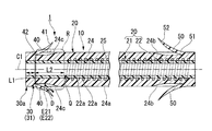
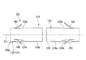
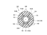
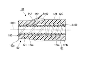
図1および図2に示すように、本実施形態に係るステント1(医療用ステント)は、第1剛性部20および第2剛性部30を有する本体10と、フラップ(係止部材)40とを備えている。第1剛性部20および第2剛性部30は、長手軸C1に沿って管状に形成されているフラップ40は、本体10の径方向外方に延びた延部41と、この延部41と連なって第2剛性部30に固定された基端部42とを有する。 (First embodiment)
As shown in FIGS. 1 and 2, the stent 1 (medical stent) according to this embodiment includes amain body 10 having a first rigid portion 20 and a second rigid portion 30, and a flap (locking member) 40. I have. The first rigid portion 20 and the second rigid portion 30 have a flap 40 formed in a tubular shape along the longitudinal axis C <b> 1, and an extended portion 41 extending radially outward of the main body 10, and the extended portion 41. And a base end portion 42 fixed to the second rigid portion 30.
図1および図2に示すように、本実施形態に係るステント1(医療用ステント)は、第1剛性部20および第2剛性部30を有する本体10と、フラップ(係止部材)40とを備えている。第1剛性部20および第2剛性部30は、長手軸C1に沿って管状に形成されているフラップ40は、本体10の径方向外方に延びた延部41と、この延部41と連なって第2剛性部30に固定された基端部42とを有する。 (First embodiment)
As shown in FIGS. 1 and 2, the stent 1 (medical stent) according to this embodiment includes a
第1剛性部20は、管状に形成された第1樹脂部21と、第1樹脂部21に固着されたコイル(第1補強部)22とを有している。
第1樹脂部21は、管状に形成された外部層24の先端部と、管状に形成され、外部層24と同軸に外部層24の内周側に設けられた内部層25の先端部とを含む。 The firstrigid portion 20 includes a first resin portion 21 formed in a tubular shape, and a coil (first reinforcement portion) 22 fixed to the first resin portion 21.
Thefirst resin portion 21 includes a distal end portion of the outer layer 24 formed in a tubular shape, and a distal end portion of the inner layer 25 that is formed in a tubular shape and is provided coaxially with the outer layer 24 on the inner peripheral side of the outer layer 24. Including.
第1樹脂部21は、管状に形成された外部層24の先端部と、管状に形成され、外部層24と同軸に外部層24の内周側に設けられた内部層25の先端部とを含む。 The first
The
外部層24は、ウレタンやポリエチレンなどの弾性、柔軟性および生体適合性を有する樹脂材料で形成されている。外部層24は、例えば外径が3.2mm(10フレンチ)、長さが100mmである。外部層24は、コイル22の外周面側だけでなく、コイル22の後述する素線22a同士の隙間にも設けられている。
The outer layer 24 is formed of a resin material having elasticity, flexibility, and biocompatibility such as urethane and polyethylene. For example, the outer layer 24 has an outer diameter of 3.2 mm (10 French) and a length of 100 mm. The outer layer 24 is provided not only on the outer peripheral surface side of the coil 22 but also in a gap between the strands 22 a described later of the coil 22.
本実施形態では、胆管内に挿入されるときに先端側となる外部層24の第2剛性部30とは反対側となる端部に、4つのフラップ50が形成されている(1つのフラップ50は不図示。)。フラップ50は、外部層24の一部に長尺方向に切り込みを入れ、切り込んだ部分を起こすことにより形成されている。すなわち、フラップ50の材質は、外部層24の材質と同一である。4つのフラップ50は、長手軸C1周りに等角度の間隔で形成されている。フラップ50は、外部層24における第2剛性部30とは反対側の端部(第1端)の外周面に第一端部51が固定され、第二端部52が長手軸C1に沿って外部層24の中央部24a側に延びつつ本体10の径方向外側に開くように形成されている。
In the present embodiment, four flaps 50 are formed at the end portion of the outer layer 24 that is the distal end side when inserted into the bile duct on the side opposite to the second rigid portion 30 (one flap 50). Is not shown.) The flap 50 is formed by cutting a part of the outer layer 24 in the longitudinal direction and raising the cut part. That is, the material of the flap 50 is the same as the material of the outer layer 24. The four flaps 50 are formed at equiangular intervals around the longitudinal axis C1. The flap 50 has a first end 51 fixed to the outer peripheral surface of the outer layer 24 opposite to the second rigid portion 30 (first end), and a second end 52 along the longitudinal axis C1. The outer layer 24 is formed so as to open to the outer side in the radial direction of the main body 10 while extending toward the central portion 24 a side.
外部層24の各フラップ50に対応する位置の外周面には、切欠き部24bが形成されている。フラップ50が径方向外側から長手軸C1に向けて押付けられたときに、フラップ50が切欠き部24bに収容される。
A notch 24b is formed on the outer peripheral surface of the outer layer 24 at a position corresponding to each flap 50. When the flap 50 is pressed from the radially outer side toward the longitudinal axis C1, the flap 50 is accommodated in the notch 24b.
内部層25は、PTFE(ポリテトラフルオロエチレン)やPFA(パーフルオロアルコキシルアルカン)などの、表面が滑らかであって生体適合性を有する樹脂材料で形成されている。内部層25と前述の外部層24とは、熱溶着などにより固定されている。
The inner layer 25 is made of a resin material having a smooth surface and biocompatibility, such as PTFE (polytetrafluoroethylene) or PFA (perfluoroalkoxyalkane). The inner layer 25 and the aforementioned outer layer 24 are fixed by heat welding or the like.
コイル22は、素線22aが長手軸C1周りに一定のピッチで螺線状に巻回されて形成されて構成されている。コイル22は、素線22aを1巻き以上巻回することで全体として管状に形成されている。素線22aは、タングステン鋼やステンレス鋼などのX線不透過性を有する。素線22aは、外部層24および内部層25よりも弾性率(引張強度)の大きい金属で形成されている。素線22aの長手方向に直交する断面は、円形に形成されている。本実施形態では、素線22aの外径は、例えば0.11mmである。素線22aの長手軸C1に沿う方向のピッチは、例えば0.41mm程度(素線22a同士の隙間は0.30mm程度。)である。コイル22の素線22aは、外部層24および内部層25に対して固定(固着)されている。
The coil 22 is formed by winding a wire 22a around a longitudinal axis C1 in a spiral shape at a constant pitch. The coil 22 is formed in a tubular shape as a whole by winding one or more turns of the wire 22a. The strand 22a has radiopacity such as tungsten steel or stainless steel. The strand 22a is formed of a metal having a larger elastic modulus (tensile strength) than the outer layer 24 and the inner layer 25. The cross section orthogonal to the longitudinal direction of the strand 22a is formed in a circle. In the present embodiment, the outer diameter of the strand 22a is, for example, 0.11 mm. The pitch of the strands 22a in the direction along the longitudinal axis C1 is, for example, about 0.41 mm (the gap between the strands 22a is about 0.30 mm). The wire 22 a of the coil 22 is fixed (fixed) to the outer layer 24 and the inner layer 25.
コイル22は、外部層24と内部層25との境界部分に第1樹脂部21と同軸に設けられている。すなわち、コイル22は第1樹脂部21の内部、例えば、径方向の略中間部に設けられている。第1剛性部20において、コイル22は第1樹脂部21の管状形状を維持するために設けられている。第1剛性部20は、径方向への圧縮力に対して所定の剛性を有している。ここで言う剛性とは、ステントを径方向に潰す力に対する耐力を主に意味する。
The coil 22 is provided coaxially with the first resin portion 21 at the boundary between the outer layer 24 and the inner layer 25. That is, the coil 22 is provided inside the first resin portion 21, for example, at a substantially intermediate portion in the radial direction. In the first rigid portion 20, the coil 22 is provided to maintain the tubular shape of the first resin portion 21. The first rigid portion 20 has a predetermined rigidity with respect to a compressive force in the radial direction. The rigidity mentioned here mainly means the proof strength against the force that crushes the stent in the radial direction.
第2剛性部30は、長手軸C1に沿って管状に形成されている。第2剛性部30は、樹脂材料で管状に形成された第2樹脂部31を有している。第2樹脂部31は、前述の外部層24の基端部と、内部層25の基端部とを含んでいる。第2樹脂部31、すなわち第2剛性部30は、第1樹脂部21の基端部と略同軸(同軸も含む。)に連なっている。第2剛性部30は、コイル22を備えないので、第1剛性部20より低い剛性を有している。第2剛性部30は、第1剛性部20の基端側において第1剛性部20の基端部と略同軸に連なることで、第1剛性部20と接続されている。
The second rigid portion 30 is formed in a tubular shape along the longitudinal axis C1. The 2nd rigid part 30 has the 2nd resin part 31 formed in the tubular shape with the resin material. The second resin portion 31 includes the base end portion of the outer layer 24 and the base end portion of the inner layer 25 described above. The second resin portion 31, that is, the second rigid portion 30 is connected to the base end portion of the first resin portion 21 substantially coaxially (including coaxial). Since the second rigid portion 30 does not include the coil 22, the second rigid portion 30 has rigidity lower than that of the first rigid portion 20. The second rigid portion 30 is connected to the first rigid portion 20 by being substantially coaxial with the proximal end portion of the first rigid portion 20 on the proximal end side of the first rigid portion 20.
フラップ40は、胆管内に挿入されるときに基端側となる外部層24の第1剛性部20とは反対側となる端部に4つ形成されている(1つのフラップ40は不図示。)。フラップ40は、外部層24の一部を切起こすことにより形成されている。すなわち、フラップ40の材質は、外部層24の材質と同一である。4つのフラップ40は、長手軸C1周りに等角度の間隔で形成されている。
フラップ40は、延部41と基端部42とを有する。フラップ40は、第2樹脂部31における第1剛性部20とは反対側の第1端30aの外周面に基端部42が固定されている。フラップ40は、延部41が長手軸C1に沿って外部層24の中央部24a側に延びつつ本体10の径方向外側に開くように形成されている。フラップ40の基端部42は、第2剛性部30の長手軸C1に沿う方向における中間部で第2剛性部30に固定されている。延部41は、第2剛性部30の長手軸C1に沿う方向における略中心位置に配置されている。 Fourflaps 40 are formed at the end portion of the outer layer 24 that is the proximal end side when inserted into the bile duct on the side opposite to the first rigid portion 20 (one flap 40 is not shown). ). The flap 40 is formed by cutting up a part of the outer layer 24. That is, the material of the flap 40 is the same as the material of the outer layer 24. The four flaps 40 are formed at equiangular intervals around the longitudinal axis C1.
Theflap 40 has an extending part 41 and a base end part 42. As for the flap 40, the base end part 42 is being fixed to the outer peripheral surface of the 1st end 30a on the opposite side to the 1st rigid part 20 in the 2nd resin part 31. FIG. The flap 40 is formed such that the extending portion 41 extends toward the central portion 24a side of the outer layer 24 along the longitudinal axis C1 and opens outward in the radial direction of the main body 10. The base end portion 42 of the flap 40 is fixed to the second rigid portion 30 at an intermediate portion in the direction along the longitudinal axis C <b> 1 of the second rigid portion 30. The extending portion 41 is disposed at a substantially central position in the direction along the longitudinal axis C1 of the second rigid portion 30.
フラップ40は、延部41と基端部42とを有する。フラップ40は、第2樹脂部31における第1剛性部20とは反対側の第1端30aの外周面に基端部42が固定されている。フラップ40は、延部41が長手軸C1に沿って外部層24の中央部24a側に延びつつ本体10の径方向外側に開くように形成されている。フラップ40の基端部42は、第2剛性部30の長手軸C1に沿う方向における中間部で第2剛性部30に固定されている。延部41は、第2剛性部30の長手軸C1に沿う方向における略中心位置に配置されている。 Four
The
長手軸C1に沿う方向において、第2剛性部30の第1剛性部20とは反対側の第1端30aからフラップ40の基端部42までの第1長さL1は、例えば5mmである。
In the direction along the longitudinal axis C1, the first length L1 from the first end 30a of the second rigid portion 30 opposite to the first rigid portion 20 to the base end portion 42 of the flap 40 is, for example, 5 mm.
外部層24の各フラップ40に対応する位置の外周面には、切欠き部24cが形成されている。フラップ40が径方向外側から長手軸C1に向けて押付けられたときに、フラップ40が切欠き部24cに収容される。
A notch 24c is formed on the outer peripheral surface of the outer layer 24 at a position corresponding to each flap 40. When the flap 40 is pressed from the radially outer side toward the longitudinal axis C1, the flap 40 is accommodated in the notch 24c.
フラップ40は、フラップ50よりも短い。基端側(十二指腸側)のフラップ40を短くすることで、内視鏡出口の鉗子起上台でフラップ40が引っ掛かることを抑制し、円滑な処置を行うことができる。
ここで、長手軸C1に沿う方向において、第1剛性部20と第2剛性部30との接続位置である境界位置Qを規定する。境界位置Qは、コイル22の基端側の端が位置する部分である。 Theflap 40 is shorter than the flap 50. By shortening the flap 40 on the proximal end side (duodenum side), it is possible to suppress the flap 40 from being caught by the forceps raising base at the endoscope exit, and to perform a smooth treatment.
Here, a boundary position Q that is a connection position between the firstrigid portion 20 and the second rigid portion 30 is defined in the direction along the longitudinal axis C1. The boundary position Q is a portion where the proximal end of the coil 22 is located.
ここで、長手軸C1に沿う方向において、第1剛性部20と第2剛性部30との接続位置である境界位置Qを規定する。境界位置Qは、コイル22の基端側の端が位置する部分である。 The
Here, a boundary position Q that is a connection position between the first
コイル22は、この境界位置Qから第2剛性部30側に設けられることなく、境界位置Qから第1剛性部20の第2剛性部30とは反対側の端部までの範囲にわたり設けられている。この例では、フラップ40の基端部42から境界位置Qまでの第2長さL2は、例えば7mmである。すなわち、前述の第2剛性部30の第1端30aからフラップ40の基端部42までの第1長さL1は、この第2長さL2以下である。
The coil 22 is provided over the range from the boundary position Q to the end of the first rigid portion 20 opposite to the second rigid portion 30 without being provided on the second rigid portion 30 side from the boundary position Q. Yes. In this example, the second length L2 from the base end portion 42 of the flap 40 to the boundary position Q is, for example, 7 mm. That is, the first length L1 from the first end 30a of the second rigid portion 30 to the base end portion 42 of the flap 40 is equal to or less than the second length L2.
ステント1の基端部は、留置時に十二指腸乳頭から十二指腸の管腔内に突出するため、第1長さL1は短い方が好ましい。しかし、外部層24にフラップ40を熱溶着などで固定する場合などには、固定強度を確保するためにも、第1長さL1を4mm以上確保することが好ましい。第2長さL2は、2mm以上8mm以下に設定することがより好ましい。
Since the proximal end portion of the stent 1 protrudes from the duodenal papilla into the duodenal lumen at the time of placement, the first length L1 is preferably shorter. However, when the flap 40 is fixed to the outer layer 24 by heat welding or the like, it is preferable to secure the first length L1 of 4 mm or more in order to ensure the fixing strength. The second length L2 is more preferably set to 2 mm or more and 8 mm or less.
本実施形態に係るステント1は、第1剛性部20及び第2剛性部30では、長手軸C1に沿う方向の位置によらず、それぞれの剛性はほぼ一定である。そして、第2剛性部30の剛性は第1剛性部20側の剛性が大きいため、この境界位置Qにおいて剛性が大きく変化している。ステント1に外力が作用したときに、剛性が大きく変化する部分の本体10は、それ以外の部分に比べて応力が集中するため破断しやすい。
以下では、第2剛性部30におけるフラップ40の基端部42の中央部24a側から境界位置Qまでの範囲を、被把持領域Rとして示す。 In thestent 1 according to this embodiment, in the first rigid portion 20 and the second rigid portion 30, the respective rigidity is substantially constant regardless of the position along the longitudinal axis C1. Since the rigidity of the second rigid portion 30 is large on the first rigid portion 20 side, the rigidity changes greatly at the boundary position Q. When an external force is applied to the stent 1, the main body 10 at a portion where the rigidity changes greatly is more likely to break because stress concentrates compared to other portions.
Hereinafter, a range from thecentral portion 24a side of the base end portion 42 of the flap 40 in the second rigid portion 30 to the boundary position Q is shown as a gripped region R.
以下では、第2剛性部30におけるフラップ40の基端部42の中央部24a側から境界位置Qまでの範囲を、被把持領域Rとして示す。 In the
Hereinafter, a range from the
次に、以上のように構成されたステント1の作用について、ステント1を胆管に留置し、さらに留置したステント1を交換する手技を例として以下に説明する。
Next, the operation of the stent 1 configured as described above will be described below by taking as an example a technique for placing the stent 1 in the bile duct and further replacing the placed stent 1.
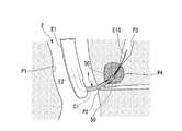
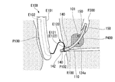
まず、術者などの使用者は、口等の自然開口から側視タイプの内視鏡を患者の体腔内に挿入し、図3に示すように、内視鏡Eの挿入部E1の先端を、十二指腸P1を通して十二指腸乳頭(組織)P2付近まで進入させる。
First, a user such as an operator inserts a side-viewing type endoscope into a patient's body cavity through a natural opening such as a mouth, and the distal end of the insertion portion E1 of the endoscope E is inserted as shown in FIG. , Through the duodenum P1 to the vicinity of the duodenal papilla (tissue) P2.
次に、使用者は、内視鏡Eの不図示の鉗子口からチャンネルE2にガイドワイヤE10を挿入し、不図示の起上台を適宜操作しながら、ガイドワイヤE10の先端をチャンネルE2の先端開口から十二指腸乳頭P2に向かって突出させる。そして、ガイドワイヤE10の先端を十二指腸乳頭P2から胆管P3内に挿入する。
Next, the user inserts the guide wire E10 into the channel E2 from the forceps opening (not shown) of the endoscope E, and appropriately operates the raising base (not shown), and the tip of the guide wire E10 is opened to the tip of the channel E2. Project toward the duodenal papilla P2. Then, the distal end of the guide wire E10 is inserted from the duodenal papilla P2 into the bile duct P3.
さらに、使用者は、X線透視下において、十二指腸乳頭P2と胆管P3の狭窄部P4の形状を確認して、好適な長さのステント1を選択する。すなわち、各フラップ40、50が開いたときの、フラップ40の延部41からフラップ50の第二端部52までの長さが、十二指腸乳頭P2から胆管P3の狭窄部P4を越える位置までの長さを有するステント1を選択する。
Further, the user confirms the shapes of the stenosis P4 of the duodenal papilla P2 and the bile duct P3 under X-ray fluoroscopy, and selects the stent 1 having a suitable length. That is, when each flap 40, 50 is opened, the length from the extension 41 of the flap 40 to the second end 52 of the flap 50 is the length from the duodenal papilla P2 to the position beyond the constriction P4 of the bile duct P3. A stent 1 having a thickness is selected.
次に、使用者は、ステント1と胆管P3の位置と形状を確認しながら、鉗子口から挿入した不図示のステントデリバリーカテーテルにより、ガイドワイヤE10に沿わせてステント1をフラップ50側から胆管P3内に挿入する。
Next, while confirming the position and shape of the stent 1 and the bile duct P3, the user uses the stent delivery catheter (not shown) inserted from the forceps opening to place the stent 1 along the guide wire E10 from the flap 50 side to the bile duct P3. Insert inside.
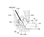
ステント1の先端が胆管P3の狭窄部P4に達すると、フラップ50は狭窄部P4により長手軸C1に向けて押付けられ、フラップ50が切欠き部24bにそれぞれ収容される。ステント1が胆管P3内にさらに挿入されフラップ50が狭窄部P4を越えると、図4に示すように、フラップ50の第二端部52側が開き、フラップ50が狭窄部P4に係止する。
When the distal end of the stent 1 reaches the constriction P4 of the bile duct P3, the flap 50 is pressed toward the longitudinal axis C1 by the constriction P4, and the flap 50 is accommodated in the notch 24b. When the stent 1 is further inserted into the bile duct P3 and the flap 50 exceeds the constriction P4, the second end 52 side of the flap 50 is opened as shown in FIG. 4, and the flap 50 is locked to the constriction P4.
このとき、フラップ40の延部41からフラップ50の第二端部52までの長さが上記の長さを有するステント1を選択しているので、フラップ40も十二指腸乳頭P2に係止する。これにより、第2剛性部30の少なくとも基端部は、十二指腸乳頭P2から十二指腸P1の管腔内に突出されて留置される。言い換えれば、フラップ40の基端部42よりもやや中央部24a側の本体10の外周面は、留置時には十二指腸P1の管腔内に突出している。一方で、第1剛性部20は胆管P3内に留置される。
At this time, since the stent 1 having the length from the extended portion 41 of the flap 40 to the second end portion 52 of the flap 50 is selected, the flap 40 is also locked to the duodenal papilla P2. As a result, at least the base end portion of the second rigid portion 30 protrudes from the duodenal papilla P2 into the lumen of the duodenum P1 and is placed. In other words, the outer peripheral surface of the main body 10 on the side of the central portion 24a slightly from the base end portion 42 of the flap 40 protrudes into the lumen of the duodenum P1 when indwelling. On the other hand, the 1st rigid part 20 is detained in the bile duct P3.
ステント1の境界位置Qは、十二指腸乳頭P2の近傍に位置する。すなわち、第2剛性部30は、ほぼ十二指腸P1内に位置する。したがって、ステント1において、胆管P3などで押付けられる部分の管路内の空間は、コイル22により保持される。
The boundary position Q of the stent 1 is located in the vicinity of the duodenal papilla P2. That is, the 2nd rigid part 30 is located in the duodenum P1 substantially. Therefore, in the stent 1, the space in the duct that is pressed by the bile duct P <b> 3 or the like is held by the coil 22.
次に、使用者は、ガイドワイヤE10および内視鏡Eの挿入部E1を患者の体腔内から取出し、ステント1を留置する手技を終了する。この後で、ステント1を一定期間留置したら、以下に説明するように留置したステント1を新しいステント1に交換する。
Next, the user removes the guide wire E10 and the insertion portion E1 of the endoscope E from the body cavity of the patient, and ends the procedure of placing the stent 1. Thereafter, when the stent 1 is placed for a certain period, the placed stent 1 is replaced with a new stent 1 as described below.
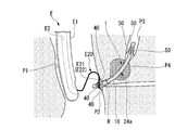
まず、前述のように、使用者は図5に示すように、内視鏡Eの挿入部E1の先端を、十二指腸P1を通して十二指腸乳頭P2付近まで挿入する。
First, as described above, the user inserts the distal end of the insertion portion E1 of the endoscope E through the duodenum P1 to the vicinity of the duodenal papilla P2 as described above.
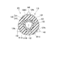
鉗子口を通してチャンネルE2に、スネアE20を挿通させる。このときに用いるスネアE20は、スネアE20のループ部E21を構成するワイヤE22の外径D(図2参照。)が前述の第2長さL2よりも充分小さいものを選定する。なお、ループ部E21は、ワイヤE22がループ状に形成されて構成されている。
The snare E20 is inserted into the channel E2 through the forceps opening. The snare E20 used at this time is selected such that the outer diameter D (see FIG. 2) of the wire E22 constituting the loop portion E21 of the snare E20 is sufficiently smaller than the second length L2. The loop portion E21 is configured by forming a wire E22 in a loop shape.
鉗子口に対してスネアE20を押込み、チャンネルE2の先端開口からループ部E21を突出させる。ループ部E21にステント1の基端側を通して、ステント1の被把持領域Rにループ部E21を掛ける。より詳しくは、フラップ40の基端部42よりもやや中央部24a側の本体10の外周面にループ部E21を掛ける。
The snare E20 is pushed into the forceps opening, and the loop portion E21 is protruded from the tip opening of the channel E2. The loop portion E21 is hung on the gripped region R of the stent 1 through the proximal end side of the stent 1 through the loop portion E21. More specifically, the loop portion E21 is hung on the outer peripheral surface of the main body 10 on the side of the central portion 24a slightly from the base end portion 42 of the flap 40.
挿入部E1の位置を固定した状態でスネアE20を引戻すと、図2および図5に示すように、ループ部E21が本体10におけるフラップ40の基端部42の中央部24a側に係止する。これにより、ステント1がスネアE20に保持される。ワイヤE22の外径Dが前述の第2長さL2よりも充分小さいため、長手軸C1に沿う方向においてワイヤE22は境界位置Qから離間している。
When the snare E20 is pulled back with the position of the insertion portion E1 fixed, the loop portion E21 is locked to the central portion 24a side of the base end portion 42 of the flap 40 in the main body 10 as shown in FIGS. . Thereby, the stent 1 is hold | maintained at the snare E20. Since the outer diameter D of the wire E22 is sufficiently smaller than the second length L2, the wire E22 is separated from the boundary position Q in the direction along the longitudinal axis C1.
スネアE20を引戻していくと、胆管P3からステント1が引抜かれるとともに、図6に示すように、挿入部E1のチャンネルE2にステント1が引込まれる。このとき、ステント1の保持された被把持領域RがチャンネルE2に先に入り、ステント1における被把持領域Rよりも先端側の部分、および基端側の部分である第2剛性部30の第1端30aが続いてチャンネルE2に入る。すなわち、被把持領域Rで折返された状態でステント1がチャンネルE2に引込まれる。ステント1が折返された部分では、ステント1全体としての外径が大きくなるため、図7に示すように、チャンネルE2に引込まれるときにステント1が径方向に潰される。
When the snare E20 is pulled back, the stent 1 is pulled out from the bile duct P3 and, as shown in FIG. 6, the stent 1 is pulled into the channel E2 of the insertion portion E1. At this time, the grasped region R held by the stent 1 enters the channel E2 first, and the first rigid portion 30 of the second rigid portion 30 that is the distal end portion and the proximal end portion of the stent 1 relative to the grasped region R. One end 30a then enters channel E2. That is, the stent 1 is drawn into the channel E2 while being folded in the grasped region R. Since the outer diameter of the stent 1 as a whole is increased at the portion where the stent 1 is folded, as shown in FIG. 7, the stent 1 is crushed in the radial direction when it is drawn into the channel E2.
前述の第1長さL1は第2長さL2よりも短いため、ステント1における折返されて重なる部分のいずれにもコイル22が設けられていない。このため、重なる部分の外径は容易に小さくなる。ワイヤE22が境界位置Qから離間しているため、ステント1の境界位置QにワイヤE22が食込むなど、ステント1の境界位置Qに過剰な力が作用しない。ステント1の折返されて重なる部分がチャンネルE2を通ると、ステント1の残りの部分も連動するようにチャンネルE2を通る。
Since the first length L1 is shorter than the second length L2, the coil 22 is not provided in any of the folded and overlapping portions of the stent 1. For this reason, the outer diameter of the overlapping portion is easily reduced. Since the wire E22 is separated from the boundary position Q, an excessive force does not act on the boundary position Q of the stent 1, for example, the wire E22 bites into the boundary position Q of the stent 1. When the folded and overlapped portion of the stent 1 passes through the channel E2, it passes through the channel E2 so that the remaining portion of the stent 1 is also interlocked.
このように、挿入部E1の位置を固定した状態でスネアE20を引戻し、チャンネルE2を通してステント1およびスネアE20を体外に引抜く。これ以降は、前述のようにチャンネルE2にガイドワイヤE10を挿入し、チャンネルE2を通して新しいステント1を胆管P3内に留置する。
Thus, with the position of the insertion portion E1 fixed, the snare E20 is pulled back, and the stent 1 and the snare E20 are pulled out of the body through the channel E2. Thereafter, the guide wire E10 is inserted into the channel E2 as described above, and the new stent 1 is placed in the bile duct P3 through the channel E2.
本実施形態に係るステント1によれば、第1剛性部20は第2剛性部30よりも剛性が高いため、留置時に胆管P3などで押付けられる部分の管路内の空間が保持される。第2剛性部30は第1剛性部20よりも剛性が低いので、ステント1を回収するためにチャンネルE2に通すときにチャンネルE2に最初に引込まれる部分であって第2剛性部30の一部である被把持領域Rを容易に潰す、すなわち変形させることができる。
According to the stent 1 according to the present embodiment, the first rigid portion 20 is higher in rigidity than the second rigid portion 30, so that the space in the portion of the duct that is pressed by the bile duct P3 at the time of placement is maintained. Since the second rigid portion 30 is lower in rigidity than the first rigid portion 20, the second rigid portion 30 is a portion that is first drawn into the channel E 2 when the stent 1 is passed through the channel E 2 to recover the stent 1. It is possible to easily crush, that is, deform, the gripped region R that is a portion.
前述のようにスネアE20のワイヤE22の外径Dを選定することで、ループ部E21がフラップ40の基端部42に係止したときにワイヤE22は境界位置Qから離間している。したがって、ステント1の剛性が大きく変化する境界位置Qに過剰な力が作用して、本体10が境界位置Qで引きちぎられて破断するのを抑制することができる。
By selecting the outer diameter D of the wire E22 of the snare E20 as described above, the wire E22 is separated from the boundary position Q when the loop portion E21 is locked to the proximal end portion 42 of the flap 40. Therefore, it is possible to suppress the excessive force from acting on the boundary position Q where the rigidity of the stent 1 greatly changes and the main body 10 being torn at the boundary position Q and breaking.
第2剛性部30の第1端30aからフラップ40の基端部42までの第1長さL1は、フラップ40の基端部42から境界位置Qまでの第2長さL2以下である。これにより、ステント1が挿入部E1のチャンネルE2に引込まれる際に被把持領域Rで折返されたきに、折返されて重なる部分にコイル22がない。このため、重なる部分を容易に潰す、すなわち変形させることができる。したがって、この重なる部分の全体としての外径が大きくなるのを抑えることができる。
The first length L1 from the first end 30a of the second rigid portion 30 to the base end portion 42 of the flap 40 is equal to or less than the second length L2 from the base end portion 42 of the flap 40 to the boundary position Q. Thus, when the stent 1 is folded back in the gripped region R when the stent 1 is pulled into the channel E2 of the insertion portion E1, there is no coil 22 in the portion that is folded back and overlapped. For this reason, the overlapping portion can be easily crushed, that is, deformed. Therefore, it can suppress that the outer diameter as the whole of this overlapping part becomes large.
なお、本実施形態では、第2剛性部30の第1端30aからフラップ40の基端部42までの第1長さL1は、フラップ40の基端部42から境界位置Qまでの第2長さL2より長くてもよい。このように構成されていても、第2剛性部30を潰して、ステント1の折返された部分の外径を抑えることができるからである。
In the present embodiment, the first length L1 from the first end 30a of the second rigid portion 30 to the base end portion 42 of the flap 40 is the second length from the base end portion 42 of the flap 40 to the boundary position Q. It may be longer than L2. This is because the second rigid portion 30 can be crushed and the outer diameter of the folded portion of the stent 1 can be suppressed even with such a configuration.
本実施形態では、第1補強部としてコイル22を用いた。しかし、第1補強部はこれに限ることなく、例えば図8に示すステント2のように、第1補強部としてブレード60を用いてもよい。ブレード60は、金属製の素線を網状に編んだ構成の公知のブレードを使用できる。
In the present embodiment, the coil 22 is used as the first reinforcing portion. However, the first reinforcing portion is not limited to this, and a blade 60 may be used as the first reinforcing portion, for example, as in the stent 2 shown in FIG. As the blade 60, a known blade having a configuration in which metal strands are knitted in a net shape can be used.
例えば、本実施形態では、ステントを体外に引抜くのにスネアE20を用いた。しかし、スネアE20に代えて、把持鉗子などを用いてステントの被把持領域Rを把持したり、フラップ40の基端部42に引っ掛けるなどしてステントを引抜いてもよい。把持鉗子を用いる場合には、ステント1を把持する把持片の幅が前述の第2長さL2よりも充分小さいものを選定することが好ましい。
For example, in this embodiment, the snare E20 is used to pull the stent out of the body. However, instead of the snare E20, the grasped region R of the stent may be grasped using grasping forceps or the like, or the stent 40 may be pulled out by being hooked on the proximal end portion 42 of the flap 40. When using grasping forceps, it is preferable to select a grasping piece that grasps the stent 1 having a width sufficiently smaller than the second length L2.
本実施形態では、ステント1の外部層24の基端側に4つのフラップ40が固定されている構成とした。しかし、外部層24に固定されるフラップ40の数に制限はなく、1から3でもよいし、5以上でもよい。本実施形態では、4つのフラップ40は、長手軸C1周りに等角度の間隔で形成されている例を示したが、これらのフラップ40は、長手軸C1周りに等角度の間隔で形成されていなくてもよい。外部層24の先端側に固定されるフラップ50の数、配置についても同様である。
In the present embodiment, the four flaps 40 are fixed to the proximal end side of the outer layer 24 of the stent 1. However, the number of the flaps 40 fixed to the outer layer 24 is not limited, and may be 1 to 3, or 5 or more. In this embodiment, the four flaps 40 are formed at equiangular intervals around the longitudinal axis C1, but these flaps 40 are formed at equiangular intervals around the longitudinal axis C1. It does not have to be. The same applies to the number and arrangement of the flaps 50 fixed to the front end side of the outer layer 24.
本実施形態では、ステントの外部層24に4つのフラップ50が固定されている例を示したが、ステントにこれらのフラップ50は備えられなくてもよい。
In the present embodiment, an example in which the four flaps 50 are fixed to the outer layer 24 of the stent is shown, but these flaps 50 may not be provided in the stent.
本実施形態では、フラップ40は、切り込みをいれて切り込んだ部分を起こすことにより形成した。しかし、外部層24とは別に形成した部材を外部層24に熱溶着などで固定することで、フラップ40を形成してもよい。フラップ50についても同様である。
In this embodiment, the flap 40 is formed by raising a cut portion by making a cut. However, the flap 40 may be formed by fixing a member formed separately from the outer layer 24 to the outer layer 24 by heat welding or the like. The same applies to the flap 50.
本実施形態では、ステント1を胆管P3内に留置する場合について説明した。しかし、本ステント1は膵管内に留置して用いてもよい。
In the present embodiment, the case where the stent 1 is placed in the bile duct P3 has been described. However, the stent 1 may be used by being placed in the pancreatic duct.
(第二実施形態)
以下、本発明に係るステントの第二実施形態を、図9から図26を参照しながら説明する。なお、以下の全ての図面においては、図面を見やすくするため、各構成要素の厚さや寸法の比率は適宜変更して示している。 (Second embodiment)
Hereinafter, a second embodiment of the stent according to the present invention will be described with reference to FIGS. 9 to 26. In all of the drawings below, the thicknesses and dimensional ratios of the constituent elements are appropriately changed for easy understanding of the drawings.
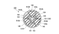
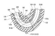
図9および図10に示すように、本実施形態に係るステント101(医療用ステント)は、第1剛性部120および第2剛性部130を有する本体110と、フラップ(係止部材)140とを備えている。本体110は、長手軸C101に沿って管状に形成された第1剛性部120および第2剛性部130を有する。フラップ140は、本体110の径方向外方に延びた延部141と、この延部141と連なって第2剛性部130に固定された基端部142とを有する。
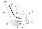
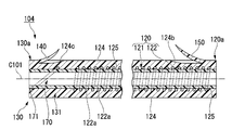
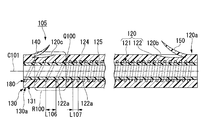
As shown in FIGS. 9 and 10, the stent 101 (medical stent) according to this embodiment includes a main body 110 having a first rigid portion 120 and a second rigid portion 130, and a flap (locking member) 140. I have. The main body 110 has a first rigid portion 120 and a second rigid portion 130 formed in a tubular shape along the longitudinal axis C101. The flap 140 includes an extending portion 141 that extends outward in the radial direction of the main body 110, and a base end portion 142 that is connected to the extending portion 141 and is fixed to the second rigid portion 130.
第1剛性部120は、第1樹脂部121と、コイル(第1補強部)122とを有している。第1樹脂部121は、管状に形成されている。コイル122は、第1樹脂部121に固着されている。第1樹脂部121は、管状に形成された外部層124の先端部と、管状に形成され、外部層124と同軸に外部層124の内周側に設けられた内部層125の先端部とを含んでいる。外部層124は、ウレタンやポリエチレンなどの弾性、柔軟性および生体適合性を有する樹脂材料で形成されている。外部層124は、例えば外径が3.2mm(10フレンチ)、長さが100mmである。外部層124は、コイル122の外周面側だけでなく、コイル122の後述する素線122a同士の隙間にも設けられている。
The first rigid portion 120 has a first resin portion 121 and a coil (first reinforcing portion) 122. The first resin part 121 is formed in a tubular shape. The coil 122 is fixed to the first resin portion 121. The first resin portion 121 includes a distal end portion of the outer layer 124 formed in a tubular shape, and a distal end portion of the inner layer 125 that is formed in a tubular shape and is provided coaxially with the outer layer 124 on the inner peripheral side of the outer layer 124. Contains. The outer layer 124 is formed of a resin material having elasticity, flexibility, and biocompatibility such as urethane and polyethylene. For example, the outer layer 124 has an outer diameter of 3.2 mm (10 French) and a length of 100 mm. The outer layer 124 is provided not only on the outer peripheral surface side of the coil 122 but also in a gap between the strands 122 a described later of the coil 122.
この例では、胆管内に挿入されるときに先端側となる外部層124の第2剛性部130とは反対側となる端部に、3つのフラップ150が形成されている(1つのフラップ150は不図示。)。フラップ150は、外部層124の一部に切り込みをいれ、切り込んだ部分を起こすことにより形成されている。すなわち、フラップ150の材質は、外部層124の材質と同一である。3つのフラップ150は、長手軸C101周りに等角度の間隔で形成されている。フラップ150は、外部層124における第2剛性部130とは反対側の第2端120aの外周面に第一端部151が固定されている。フラップ150は、第二端部152が長手軸C101に沿って外部層124の中央部124a側に延びつつ本体110の径方向外側に開くように形成されている。
In this example, three flaps 150 are formed at the end portion of the outer layer 124 that is the distal end side when inserted into the bile duct on the side opposite to the second rigid portion 130 (one flap 150 is Not shown). The flap 150 is formed by cutting a part of the outer layer 124 and raising the cut part. That is, the material of the flap 150 is the same as that of the outer layer 124. The three flaps 150 are formed at equiangular intervals around the longitudinal axis C101. The first end 151 of the flap 150 is fixed to the outer peripheral surface of the second end 120 a on the opposite side of the outer layer 124 from the second rigid portion 130. The flap 150 is formed such that the second end portion 152 extends toward the center portion 124 a side of the outer layer 124 along the longitudinal axis C <b> 101 and opens outward in the radial direction of the main body 110.
外部層124の各フラップ150に対応する位置の外周面には、切欠き部124bが形成されている。フラップ150が径方向外側から長手軸C101に向けて押付けられたときに、フラップ150が切欠き部124bに収容される。
A notch 124b is formed on the outer peripheral surface of the outer layer 124 at a position corresponding to each flap 150. When the flap 150 is pressed from the radially outer side toward the longitudinal axis C101, the flap 150 is accommodated in the notch 124b.
内部層125は、例えば、PTFE(ポリテトラフルオロエチレン)やPFA(パーフルオロアルコキシルアルカン)などの、表面が滑らかであって生体適合性を有する樹脂材料で形成されている。内部層125と前述の外部層124とは、熱溶着などにより固定されている。
The inner layer 125 is formed of a resin material having a smooth surface and biocompatibility, such as PTFE (polytetrafluoroethylene) and PFA (perfluoroalkoxyalkane). The inner layer 125 and the aforementioned outer layer 124 are fixed by heat welding or the like.
コイル122は、第1素線(素線)122aが長手軸C101周りに一定のピッチで螺線状に巻回されて構成されている。コイル122は、第1素線122aを1巻き以上巻回することで全体として管状に形成されている。第1素線122aは、タングステン鋼やステンレス鋼などのX線不透過性を有する。第1素線122aは、外部層124および内部層125よりも弾性率(引張強度)の大きい金属で形成されている。第1素線122aの長手方向に直交する断面は、円形に形成されている。本実施形態では、第1素線122aの外径は、例えば0.11mmである。第1素線122aの長手軸C101に沿う方向のピッチは、例えば0.41mm程度(第1素線122a同士の隙間は0.30mm程度。)である。コイル122の第1素線122aは、外部層124および内部層125に対して固定(固着)されている。
The coil 122 is configured by winding a first strand (strand) 122a in a spiral shape around the longitudinal axis C101 at a constant pitch. The coil 122 is formed in a tubular shape as a whole by winding one or more turns of the first strand 122a. The first strand 122a has radiopacity such as tungsten steel and stainless steel. The first strand 122a is formed of a metal having a larger elastic modulus (tensile strength) than the outer layer 124 and the inner layer 125. The cross section orthogonal to the longitudinal direction of the first strand 122a is formed in a circular shape. In the present embodiment, the outer diameter of the first strand 122a is, for example, 0.11 mm. The pitch of the first strands 122a in the direction along the longitudinal axis C101 is, for example, about 0.41 mm (the gap between the first strands 122a is about 0.30 mm). The first strand 122 a of the coil 122 is fixed (fixed) to the outer layer 124 and the inner layer 125.
コイル122は、外部層124と内部層125との境界部分に第1樹脂部121と同軸に設けられている。すなわち、コイル122は第1樹脂部121の内部、例えば、径方向の略中間部に設けられている。第1剛性部120において、コイル122は第1樹脂部121の管状形状を維持するために設けられている。第1剛性部120は、径方向への圧縮力に対して所定の剛性を有している。ここで言う剛性とは、ステントを径方向に潰す力に対する耐力を主に意味する。
The coil 122 is provided coaxially with the first resin portion 121 at a boundary portion between the outer layer 124 and the inner layer 125. That is, the coil 122 is provided inside the first resin portion 121, for example, at a substantially intermediate portion in the radial direction. In the first rigid portion 120, the coil 122 is provided to maintain the tubular shape of the first resin portion 121. The first rigid portion 120 has a predetermined rigidity with respect to a compressive force in the radial direction. The rigidity mentioned here mainly means the proof strength against the force that crushes the stent in the radial direction.
第2剛性部130は、長手軸C101に沿って管状に形成されている。第2剛性部130は、図10および図11に示すように、樹脂材料で管状に形成された第2樹脂部131と、第2樹脂部131に固着された補強板(第2補強部)132とを有している。第2樹脂部131は、前述の外部層124の基端部と、内部層125の基端部とを含んでいる。外部層124の基端部および内部層125の基端部で、第2樹脂部131の壁部を構成する。第2樹脂部131、すなわち第2剛性部130は、第1樹脂部121の基端部と略同軸(同軸も含む。)に連なっている。
The second rigid portion 130 is formed in a tubular shape along the longitudinal axis C101. As shown in FIGS. 10 and 11, the second rigid portion 130 includes a second resin portion 131 formed in a tubular shape with a resin material, and a reinforcing plate (second reinforcing portion) 132 fixed to the second resin portion 131. And have. The second resin portion 131 includes the base end portion of the outer layer 124 and the base end portion of the inner layer 125 described above. The base portion of the outer layer 124 and the base end portion of the inner layer 125 form a wall portion of the second resin portion 131. The second resin portion 131, that is, the second rigid portion 130 is connected to the base end portion of the first resin portion 121 substantially coaxially (including coaxial).
フラップ140は、胆管内に挿入されるときに基端側となる外部層124の第1剛性部120とは反対側となる第1端130aに3つ形成されている(1つのフラップ140は不図示。)。フラップ140は、外部層124の一部を切り込んで、切り込んだ部分を起こすことにより形成されている。すなわち、フラップ140の材質は、外部層124の材質と同一である。3つのフラップ140は、長手軸C101周りに等角度の間隔で形成されている。
Three flaps 140 are formed at the first end 130a on the opposite side of the first rigid portion 120 of the outer layer 124 which is the proximal end side when inserted into the bile duct (one flap 140 is not formed). Illustrated.) The flap 140 is formed by cutting a part of the outer layer 124 and raising the cut part. That is, the material of the flap 140 is the same as the material of the outer layer 124. The three flaps 140 are formed at equiangular intervals around the longitudinal axis C101.
フラップ140は、延部141と基端部142とを有する。フラップ140は、第2樹脂部131における第1剛性部120とは反対側の第1端130aの外周面に基端部142が固定されている。フラップ140は、延部141が長手軸C101に沿って外部層124の中央部124a側に延びつつ本体110の径方向外側に開くように形成されている。フラップ140の基端部142は、第2剛性部130の長手軸C101に沿う方向における中間部で第2剛性部130に固定されている。延部141は、第2剛性部130の長手軸C101に沿う方向における略中心位置に配置されている。
The flap 140 has an extended portion 141 and a proximal end portion 142. As for the flap 140, the base end part 142 is being fixed to the outer peripheral surface of the 1st end 130a on the opposite side to the 1st rigid part 120 in the 2nd resin part 131. FIG. The flap 140 is formed so that the extended portion 141 extends along the longitudinal axis C101 toward the central portion 124a of the outer layer 124 and opens radially outward of the main body 110. The base end portion 142 of the flap 140 is fixed to the second rigid portion 130 at an intermediate portion in the direction along the longitudinal axis C101 of the second rigid portion 130. The extending portion 141 is disposed at a substantially central position in the direction along the longitudinal axis C101 of the second rigid portion 130.
長手軸C101に沿う方向において、第2剛性部130の第1剛性部120とは反対側の第1端130aからフラップ140の基端部142までの第1長さL101は、例えば5mmである。
In the direction along the longitudinal axis C101, the first length L101 from the first end 130a of the second rigid portion 130 opposite to the first rigid portion 120 to the base end portion 142 of the flap 140 is, for example, 5 mm.
外部層124の各フラップ140に対応する位置の外周面には、切欠き部124cが形成されている。フラップ140が径方向外側から長手軸C101に向けて押付けられたときに、フラップ140が切欠き部124cに収容される。
A notch 124c is formed on the outer peripheral surface of the outer layer 124 at a position corresponding to each flap 140. When the flap 140 is pressed from the radially outer side toward the longitudinal axis C101, the flap 140 is accommodated in the notch 124c.
フラップ140は、フラップ150よりも短い。基端側(十二指腸側)のフラップ140を短くすることで、内視鏡出口の鉗子起上台でフラップ140が引っ掛かることを抑制し、円滑な処置を行うことができる。
ここで、図10に示すように、長手軸C101に沿う方向において、第1剛性部120と第2剛性部130との接続位置である境界位置Q100を規定する。境界位置Q100は、コイル22の基端側の端が位置する部分である。コイル122は、長手軸C101に沿う方向において、第1樹脂部121の境界位置Q100から第1剛性部120の第2剛性部130とは反対側の端部(第2端)120aまでの範囲にわたり第1樹脂部121と同軸に設けられている。この例では、フラップ140の基端部142から境界位置Q100までの第2長さL102は、例えば7mmである。 Theflap 140 is shorter than the flap 150. By shortening the flap 140 on the proximal end side (duodenum side), it is possible to suppress the flap 140 from being caught by the forceps raising base at the exit of the endoscope and perform a smooth treatment.
Here, as shown in FIG. 10, a boundary position Q100 that is a connection position between the firstrigid portion 120 and the second rigid portion 130 is defined in the direction along the longitudinal axis C101. The boundary position Q100 is a portion where the proximal end of the coil 22 is located. The coil 122 extends in the direction along the longitudinal axis C101 from the boundary position Q100 of the first resin portion 121 to the end portion (second end) 120a of the first rigid portion 120 opposite to the second rigid portion 130. The first resin portion 121 is provided coaxially. In this example, the second length L102 from the base end 142 of the flap 140 to the boundary position Q100 is, for example, 7 mm.
ここで、図10に示すように、長手軸C101に沿う方向において、第1剛性部120と第2剛性部130との接続位置である境界位置Q100を規定する。境界位置Q100は、コイル22の基端側の端が位置する部分である。コイル122は、長手軸C101に沿う方向において、第1樹脂部121の境界位置Q100から第1剛性部120の第2剛性部130とは反対側の端部(第2端)120aまでの範囲にわたり第1樹脂部121と同軸に設けられている。この例では、フラップ140の基端部142から境界位置Q100までの第2長さL102は、例えば7mmである。 The
Here, as shown in FIG. 10, a boundary position Q100 that is a connection position between the first
ステント101の基端部は、留置時に十二指腸乳頭から十二指腸の管腔内に突出するため、第1長さL101は短い方が好ましい。しかし、外部層124にフラップ140を熱溶着などで固定する場合などには、固定強度を確保するためにも、第1長さL101を4mm以上確保することが好ましい。第2長さL102は、2mm以上8mm以下に設定することがより好ましい。
Since the proximal end portion of the stent 101 protrudes from the duodenal papilla into the lumen of the duodenum when indwelling, the first length L101 is preferably shorter. However, when the flap 140 is fixed to the outer layer 124 by heat welding or the like, it is preferable to secure the first length L101 of 4 mm or more in order to ensure the fixing strength. The second length L102 is more preferably set to 2 mm or more and 8 mm or less.
補強板132は、長手軸C101に沿う方向に延びる板状に形成されている。補強板132は、硬質ウレタン、ナイロン、ステンレス鋼などの外部層124および内部層125よりも弾性率の大きい材料で形成されている。図11に示すように、本実施形態ではステント101に3枚の補強板132が備えられている。各補強板132は、長手軸C101に沿う方向に見たときに長手軸C101周りに等角度で互いに間隔を空けて、本体110の周方向において、フラップ140に重ならない位置に設けられている。すなわち、ステント1の径方向において、フラップ140と長手軸C101との間に補強板132が配置されないように固着されている。補強板132は、第2樹脂部131の長手軸C101周りの周方向に間隔を空けて設けられている。
The reinforcing plate 132 is formed in a plate shape extending in the direction along the longitudinal axis C101. The reinforcing plate 132 is formed of a material having a larger elastic modulus than the outer layer 124 and the inner layer 125 such as hard urethane, nylon, and stainless steel. As shown in FIG. 11, in the present embodiment, the stent 101 is provided with three reinforcing plates 132. Each reinforcing plate 132 is provided at a position that does not overlap the flap 140 in the circumferential direction of the main body 110 at an equal angle around the longitudinal axis C101 when viewed in the direction along the longitudinal axis C101. That is, in the radial direction of the stent 1, the reinforcing plate 132 is fixed so as not to be disposed between the flap 140 and the longitudinal axis C101. The reinforcing plates 132 are provided at intervals in the circumferential direction around the longitudinal axis C101 of the second resin portion 131.
このように、補強板132は第2樹脂部131の周方向の一部である領域R101には設けられずに、第2樹脂部131の周方向における領域R101以外の部分である残部に設けられている。周方向に隣合う補強板132同士の間には、外部層124が設けられている。
Thus, the reinforcing plate 132 is not provided in the region R101 that is a part of the second resin portion 131 in the circumferential direction, but is provided in the remaining portion that is a portion other than the region R101 in the circumferential direction of the second resin portion 131. ing. An outer layer 124 is provided between the reinforcing plates 132 adjacent in the circumferential direction.
各補強板132は、図10に示すように、長手軸C101に沿う方向において第2剛性部130の第1剛性部120とは反対側の第1端130aから境界位置Q100までの範囲にわたり設けられている。この例では、3枚の補強板132のうちの少なくとも1枚は、コイル122に接着や溶接などにより接続されている。第2剛性部130は、ステント101を本体110の径方向に潰したときに、周方向に隣合う補強板132の間の外部層124が圧縮されたり、隣合う補強板132の間から押出されたりすることで、第1剛性部120よりも低い剛性を有している。すなわち、第2剛性部130は、第1剛性部120に比べて径方向に潰れやすく構成されている。以下では、第2剛性部130におけるフラップ140の基端部142の中央部124a側から境界位置Q100までの範囲を、被把持領域R100として示す。
As shown in FIG. 10, each reinforcing plate 132 is provided over a range from the first end 130a on the opposite side of the second rigid portion 130 to the boundary position Q100 in the direction along the longitudinal axis C101. ing. In this example, at least one of the three reinforcing plates 132 is connected to the coil 122 by bonding or welding. When the stent 101 is crushed in the radial direction of the main body 110, the second rigid portion 130 compresses the outer layer 124 between the reinforcing plates 132 adjacent to each other in the circumferential direction or pushes the outer layer 124 between the adjacent reinforcing plates 132. By doing so, the first rigid portion 120 has lower rigidity. That is, the second rigid portion 130 is configured to be easily crushed in the radial direction as compared with the first rigid portion 120. Hereinafter, a range from the central portion 124a side of the base end portion 142 of the flap 140 to the boundary position Q100 in the second rigid portion 130 is shown as a gripped region R100.
次に、以上のように構成されたステント101の作用について、ステント101を胆管に留置し、さらに留置したステント101を交換する手技を例として以下に説明する。
Next, the operation of the stent 101 configured as described above will be described as an example of a technique for placing the stent 101 in the bile duct and replacing the placed stent 101.
まず、術者などの使用者は、口等の自然開口から側視タイプの内視鏡を患者の体腔内に挿入し、図12に示すように、内視鏡Eの挿入部E101の先端を、十二指腸P101を通して十二指腸乳頭(組織)P102付近まで挿入する。
First, a user such as an operator inserts a side-viewing type endoscope into a patient's body cavity through a natural opening such as a mouth, and inserts the distal end of the insertion portion E101 of the endoscope E as shown in FIG. And through the duodenum P101 to the vicinity of the duodenal papilla (tissue) P102.
次に、使用者は、内視鏡E100の不図示の鉗子口からチャンネルE102にガイドワイヤE110を挿入し、不図示の起上台を適宜操作しながら、ガイドワイヤE110の先端をチャンネルE102の先端開口から十二指腸乳頭P102に向かって突出させる。そして、ガイドワイヤE110の先端を十二指腸乳頭P102から胆管P103内に挿入する。
Next, the user inserts the guide wire E110 into the channel E102 from a forceps opening (not shown) of the endoscope E100, and appropriately operates a raising base (not shown), and the tip of the guide wire E110 is opened to the tip of the channel E102. Project toward the duodenal papilla P102. Then, the distal end of the guide wire E110 is inserted from the duodenal papilla P102 into the bile duct P103.
次に、使用者は、X線透視下において、十二指腸乳頭P102と胆管P103の狭窄部P104の形状を確認して、好適な長さのステント101を選択する。すなわち、各フラップ140、150が開いたときの、フラップ140の延部141からフラップ150の第二端部152までの長さが、十二指腸乳頭P102から胆管P103の狭窄部P104を越える位置までの長さを有するステント101を選択する。
Next, the user confirms the shapes of the stenosis P104 of the duodenal papilla P102 and the bile duct P103 under X-ray fluoroscopy, and selects the stent 101 having a suitable length. That is, the length from the extended portion 141 of the flap 140 to the second end portion 152 of the flap 150 when each of the flaps 140 and 150 is opened is the length from the duodenal papilla P102 to the position beyond the constricted portion P104 of the bile duct P103. A stent 101 having a thickness is selected.
次に、使用者は、ステント101と胆管P103の位置と形状を確認しながら、鉗子口から挿入した不図示のステントデリバリーカテーテルにより、ガイドワイヤE110に沿わせてステント101をフラップ150側から胆管P103内に挿入する。
Next, while confirming the positions and shapes of the stent 101 and the bile duct P103, the user moves the stent 101 from the flap 150 side along the guide wire E110 by using a stent delivery catheter (not shown) inserted from the forceps opening. Insert inside.
ステント101の先端が胆管P103の狭窄部P104に達すると、フラップ150は狭窄部P104により長手軸C101に向けて押付けられ、フラップ150が切欠き部124bにそれぞれ収容される。ステント101が胆管P103内にさらに挿入されフラップ150が狭窄部P104を越えると、図13に示すように、フラップ150の第二端部152側が開き、フラップ150が狭窄部P104に係止する。
When the distal end of the stent 101 reaches the constriction P104 of the bile duct P103, the flap 150 is pressed toward the longitudinal axis C101 by the constriction P104, and the flap 150 is accommodated in the notch 124b. When the stent 101 is further inserted into the bile duct P103 and the flap 150 exceeds the stenosis P104, the second end 152 side of the flap 150 is opened as shown in FIG. 13, and the flap 150 is locked to the stenosis P104.
このとき、フラップ140の延部141からフラップ150の第二端部152までの長さが上記の長さを有するステント101を選択しているので、フラップ140も十二指腸乳頭P102に係止する。これにより、第2剛性部130の少なくとも基端部は、十二指腸乳頭P102から十二指腸P101の管腔内に突出されて留置される。言い換えれば、フラップ140の基端部142よりもやや中央部124a側の本体110の外周面は、留置時には十二指腸P101の管腔内に突出している。一方で、第1剛性部120は胆管P103内に留置される。
At this time, since the stent 101 having the length from the extended portion 141 of the flap 140 to the second end 152 of the flap 150 is selected, the flap 140 is also locked to the duodenal papilla P102. As a result, at least the base end portion of the second rigid portion 130 protrudes from the duodenal papilla P102 into the lumen of the duodenum P101 and is placed. In other words, the outer peripheral surface of the main body 110 on the side of the central portion 124a slightly from the base end portion 142 of the flap 140 protrudes into the lumen of the duodenum P101 when indwelling. On the other hand, the 1st rigid part 120 is detained in the bile duct P103.
ステント101の境界位置Q100は、十二指腸乳頭P102の近傍に位置する。すなわち、第2剛性部130は、ほぼ十二指腸P101内に位置する。したがって、ステント101において胆管P103などで押付けられる部分の管路内の空間は、コイル122により保持される。
The boundary position Q100 of the stent 101 is located in the vicinity of the duodenal papilla P102. That is, the 2nd rigid part 130 is located in the duodenum P101 substantially. Accordingly, the space in the duct where the stent 101 is pressed by the bile duct P103 or the like is held by the coil 122.
次に、使用者は、ガイドワイヤE110および内視鏡E100の挿入部E101を患者の体腔内から取出し、ステント101を留置する手技を終了する。この後で、ステント101を一定期間留置したら、以下に説明するように留置したステント101を新しいステント101に交換する。
Next, the user removes the guide wire E110 and the insertion portion E101 of the endoscope E100 from the body cavity of the patient, and ends the procedure of placing the stent 101. After this, when the stent 101 is placed for a certain period, the placed stent 101 is replaced with a new stent 101 as described below.
まず、前述のように、使用者は図14に示すように、内視鏡E100の挿入部E101の先端を、十二指腸P101を通して十二指腸乳頭P102付近まで挿入する。
First, as described above, as shown in FIG. 14, the user inserts the distal end of the insertion portion E101 of the endoscope E100 through the duodenum P101 to the vicinity of the duodenal papilla P102.
鉗子口を通してチャンネルE102に、スネアE120を挿通させる。スネアE120のループ部E121は、ワイヤE122がループ状に形成されて構成されている。鉗子口に対してスネアE120を押込み、チャンネルE102の先端開口からループ部E121を突出させる。ループ部E121にステント101の基端側を通して、ステント101の被把持領域R100にループ部E121を掛ける。より詳しくは、フラップ140の基端部142よりもやや中央部124a側の本体110の外周面にループ部E121を掛ける。
The snare E120 is inserted into the channel E102 through the forceps opening. The loop portion E121 of the snare E120 is configured by forming a wire E122 in a loop shape. The snare E120 is pushed into the forceps opening, and the loop portion E121 is protruded from the tip opening of the channel E102. The loop portion E121 is hung on the grasped region R100 of the stent 101 through the proximal end side of the stent 101 through the loop portion E121. More specifically, the loop portion E121 is hung on the outer peripheral surface of the main body 110 on the side of the central portion 124a slightly from the base end portion 142 of the flap 140.
挿入部E101の位置を固定した状態でスネアE120を引戻すと、図10および図14に示すように、ループ部E121が本体110におけるフラップ140の基端部142の中央部124a側に係止する。
When the snare E120 is pulled back while the position of the insertion portion E101 is fixed, the loop portion E121 is locked to the central portion 124a side of the base end portion 142 of the flap 140 in the main body 110 as shown in FIGS. .
スネアE120を引戻していくと、胆管P103からステント101が引抜かれるとともに、図15に示すように、挿入部E101のチャンネルE102にステント101が引込まれる。このとき、ステント101の保持された被把持領域R100がチャンネルE102に先に入り、ステント101における被把持領域R100よりも先端側の部分、および基端側の部分である第2剛性部130の第1端130aが続いてチャンネルE102に入る。すなわち、被把持領域R100で折返された状態でステント101がチャンネルE102に引込まれる。ステント101が折返された部分では、ステント101全体としての外径が大きくなるため、図16および図17に示すように、チャンネルE102に引込まれるときにステント101が径方向に潰される。チャンネルE102に引込まれるときに、フラップ140が第2剛性部130の第1端130a側に折返されることがある。
When the snare E120 is pulled back, the stent 101 is pulled out from the bile duct P103, and the stent 101 is pulled into the channel E102 of the insertion portion E101 as shown in FIG. At this time, the grasped region R100 held by the stent 101 enters the channel E102 first, and the second rigid portion 130 of the second rigid portion 130 that is the distal end portion and the proximal end portion of the stent 101 with respect to the grasped region R100. One end 130a then enters channel E102. That is, the stent 101 is drawn into the channel E102 while being folded in the gripped region R100. Since the outer diameter of the stent 101 as a whole is increased at the portion where the stent 101 is folded, the stent 101 is crushed in the radial direction when it is pulled into the channel E102 as shown in FIGS. When pulled into the channel E102, the flap 140 may be folded back toward the first end 130a of the second rigid portion 130.
第2剛性部130の領域R101は、第1剛性部120に比べて周方向に圧縮させやすいため、第2剛性部130を径方向に容易に潰すことができる。周方向において、補強板132が設けられていない領域R101は補強板132が設けられている領域よりも径方向に潰れやすい。領域R101における外部層124の外周面には長手軸C101側に凹んだ窪み124eが形成される。チャンネルE102に引込まれるときに、フラップ140が折返された場合には、折返されたフラップ140が窪み124eに収容される。
Since the region R101 of the second rigid portion 130 is easier to compress in the circumferential direction than the first rigid portion 120, the second rigid portion 130 can be easily crushed in the radial direction. In the circumferential direction, the region R101 where the reinforcing plate 132 is not provided is more easily crushed in the radial direction than the region where the reinforcing plate 132 is provided. A recess 124e that is recessed toward the longitudinal axis C101 is formed on the outer peripheral surface of the outer layer 124 in the region R101. When the flap 140 is folded when pulled into the channel E102, the folded flap 140 is accommodated in the recess 124e.
チャンネルE102に引込まれるときに、ステント101の第2剛性部130は長手軸C101に沿う方向に引延ばされる。第2剛性部130には、外部層124および内部層125よりも弾性率の大きい材料で形成された補強板132が設けられている。このため、第2剛性部130の長手軸C101に沿う方向における剛性が大きい。さらに、3枚の補強板132のうちの少なくとも1枚はコイル122に接続されているため、第2剛性部130と第1剛性部120との接続部分の剛性も大きい。ステント101は、これらの構成を有するので、チャンネルE102に引込まれるときに、第2剛性部130が長手軸C101に沿う方向に引きちぎられることが抑制される。
When being pulled into the channel E102, the second rigid portion 130 of the stent 101 is stretched in the direction along the longitudinal axis C101. The second rigid portion 130 is provided with a reinforcing plate 132 made of a material having a larger elastic modulus than the outer layer 124 and the inner layer 125. For this reason, the rigidity in the direction along the longitudinal axis C101 of the 2nd rigid part 130 is large. Furthermore, since at least one of the three reinforcing plates 132 is connected to the coil 122, the rigidity of the connection portion between the second rigid portion 130 and the first rigid portion 120 is also large. Since the stent 101 has these configurations, it is suppressed that the second rigid portion 130 is torn in the direction along the longitudinal axis C101 when being pulled into the channel E102.
ステント101の折返されて重なる部分がチャンネルE102を通ると、ステント101の残りの部分も連動するようにチャンネルE102を通る。
このように、挿入部E101の位置を固定した状態でスネアE120を引戻し、チャンネルE102を通してステント101およびスネアE120を体外に引抜く。これ以降は、前述のようにチャンネルE102にガイドワイヤE110を挿入し、チャンネルE102を通して新しいステント101を胆管P103内に留置する。 When the folded and overlapped portion of thestent 101 passes through the channel E102, the remaining portion of the stent 101 passes through the channel E102 so as to be interlocked.
In this manner, the snare E120 is pulled back while the position of the insertion portion E101 is fixed, and thestent 101 and the snare E120 are pulled out of the body through the channel E102. Thereafter, the guide wire E110 is inserted into the channel E102 as described above, and the new stent 101 is placed in the bile duct P103 through the channel E102.
このように、挿入部E101の位置を固定した状態でスネアE120を引戻し、チャンネルE102を通してステント101およびスネアE120を体外に引抜く。これ以降は、前述のようにチャンネルE102にガイドワイヤE110を挿入し、チャンネルE102を通して新しいステント101を胆管P103内に留置する。 When the folded and overlapped portion of the
In this manner, the snare E120 is pulled back while the position of the insertion portion E101 is fixed, and the
本実施形態に係るステント101によれば、第1剛性部120は第2剛性部130よりも剛性が高いため、留置時に胆管P103などで押付けられる部分の管路内の空間が保持される。第2剛性部130は第1剛性部120よりも剛性が低いので、ステント101を回収するためにチャンネルE102に通すときにチャンネルE102に最初に引込まれる部分であって第2剛性部130の一部である被把持領域R100を第1剛性部120に比べて容易に径方向に潰す、すなわち変形させることができる。
According to the stent 101 according to the present embodiment, the first rigid portion 120 is higher in rigidity than the second rigid portion 130, so that the space in the portion of the duct that is pressed by the bile duct P103 or the like at the time of placement is maintained. Since the second rigid portion 130 is lower in rigidity than the first rigid portion 120, the second rigid portion 130 is a portion that is first drawn into the channel E102 when the stent 101 is passed through the channel E102 in order to retrieve the stent 101. As compared with the first rigid portion 120, the gripped region R100 that is a portion can be easily crushed, that is, deformed.
第2剛性部130には補強板132が設けられているため、長手軸C101に沿う方向における剛性が大きくなり、第2剛性部130が長手軸C101に沿う方向に引延ばされたときに破断しにくくすることができる。
Since the second rigid portion 130 is provided with the reinforcing plate 132, the rigidity in the direction along the longitudinal axis C101 increases, and the second rigid portion 130 breaks when stretched in the direction along the longitudinal axis C101. Can be difficult.
各補強板132は、長手軸C101に沿う方向に見たときに、本体110の周方向においてフラップ140に重ならない位置に設けられている。被把持領域R100にループ部E121が係止したスネアE120を引戻すと、領域R101における外部層124の外周面に窪み124eが形成される。折返されたフラップ140が窪み124eに収容されることで、折返されたステント101全体としての外径が大きくなるのを抑えることができる。
Each reinforcing plate 132 is provided at a position that does not overlap the flap 140 in the circumferential direction of the main body 110 when viewed in the direction along the longitudinal axis C101. When the snare E120 with the loop portion E121 engaged with the gripped region R100 is pulled back, a recess 124e is formed on the outer peripheral surface of the outer layer 124 in the region R101. By accommodating the folded flap 140 in the recess 124e, it is possible to prevent the outer diameter of the folded stent 101 as a whole from increasing.
補強板132は、長手軸C101に沿う方向に延びる板状に形成されているため、補強板132の構成がシンプルとなり、補強板132を容易に形成することができる。
補強板132がコイル122に接続されていることで、境界位置Q100におけるステント101の剛性を大きくすることができる。 Since the reinforcingplate 132 is formed in a plate shape extending in the direction along the longitudinal axis C101, the configuration of the reinforcing plate 132 becomes simple, and the reinforcing plate 132 can be easily formed.
Since the reinforcingplate 132 is connected to the coil 122, the rigidity of the stent 101 at the boundary position Q100 can be increased.
補強板132がコイル122に接続されていることで、境界位置Q100におけるステント101の剛性を大きくすることができる。 Since the reinforcing
Since the reinforcing
本実施形態では、ステント101の外部層124に3つのフラップ140が形成されるとともに、第2剛性部130に3枚の補強板132が備えられている。しかし、フラップ140および補強板132の数には制限はなく、外部層124に1つ以上のフラップ140が形成され、第2剛性部130に1枚以上の補強板132が備えられていればよい。本実施形態では、3つのフラップ140は、長手軸C101周りに等角度の間隔で形成されているが、これらのフラップ140は、長手軸C101周りに等角度の間隔で形成されていなくてもよい。外部層124に形成されるフラップ150の数、配置についても同様である。
In the present embodiment, three flaps 140 are formed on the outer layer 124 of the stent 101, and three reinforcing plates 132 are provided on the second rigid portion 130. However, the number of the flaps 140 and the reinforcing plates 132 is not limited, and one or more flaps 140 may be formed on the outer layer 124, and one or more reinforcing plates 132 may be provided on the second rigid portion 130. . In the present embodiment, the three flaps 140 are formed at equiangular intervals around the longitudinal axis C101, but these flaps 140 may not be formed at equiangular intervals around the longitudinal axis C101. . The same applies to the number and arrangement of the flaps 150 formed on the outer layer 124.
本実施形態では、各補強板132は長手軸C101に沿う方向において第2剛性部130の第1剛性部120とは反対側の端部から境界位置Q100までの範囲にわたり設けられている。しかし、補強板132は少なくとも被把持領域R100にわたり設けられていればよい。このように構成しても、ステント101におけるスネアE120のワイヤE122が係止される部分の剛性を大きくすることができるからである。
In the present embodiment, each reinforcing plate 132 is provided in a range from the opposite end of the second rigid portion 130 to the boundary position Q100 in the direction along the longitudinal axis C101. However, the reinforcing plate 132 may be provided over at least the gripped region R100. This is because even with this configuration, the rigidity of the portion of the stent 101 where the wire E122 of the snare E120 is locked can be increased.
本実施形態では、3枚の補強板132のうちの少なくとも1枚はコイル122に接続されているが、全ての補強板132がコイル122に接続されていないように構成してもよい。この場合、境界位置Q100におけるステント101の剛性は小さくなる。
In the present embodiment, at least one of the three reinforcing plates 132 is connected to the coil 122, but all the reinforcing plates 132 may not be connected to the coil 122. In this case, the rigidity of the stent 101 at the boundary position Q100 is reduced.
ステント101を交換するときに用いるスネアE120は、ループ部E121を構成するワイヤE122の外径D(図10参照。)が前述の第2長さL102よりも充分小さいものを選定する。このようなスネアE120を用いることで、ループ部E121を被把持領域Rに係止させたときに、長手軸C101に沿う方向においてワイヤE122が境界位置Q100から離間する。剛性が小さくなったステント101の境界位置Q100に過剰な力が作用すると境界位置Q100で破断することが考えられる。しかし、前述のようにスネアE120を選定することで、全ての補強板132がコイル122に接続されていない場合にステント101が境界位置Q100で破断しにくくすることができる。
As the snare E120 used when replacing the stent 101, a snare E120 having a sufficiently smaller outer diameter D (see FIG. 10) of the wire E122 constituting the loop portion E121 than the above-described second length L102 is selected. By using such a snare E120, when the loop portion E121 is locked to the gripped region R, the wire E122 is separated from the boundary position Q100 in the direction along the longitudinal axis C101. If an excessive force is applied to the boundary position Q100 of the stent 101 whose rigidity has become small, it is considered that the fracture occurs at the boundary position Q100. However, by selecting the snare E120 as described above, the stent 101 can be made difficult to break at the boundary position Q100 when all the reinforcing plates 132 are not connected to the coil 122.
(第三実施形態)
次に、本発明に係る第三実施形態について図18から図22を参照しながら説明するが、前記実施形態と同一の部位には同一の符号を付してその説明は省略し、異なる点についてのみ説明する。
図18に示すように、本実施形態に係るステント102(医療用ステント)は、第二実施形態に係るステント101の補強板132に代えて複数の棒状体(第2補強部)161を備えている。 (Third embodiment)
Next, a third embodiment according to the present invention will be described with reference to FIGS. 18 to 22. However, the same parts as those in the above embodiment are denoted by the same reference numerals, and the description thereof will be omitted. Only explained.
As shown in FIG. 18, the stent 102 (medical stent) according to this embodiment includes a plurality of rod-like bodies (second reinforcing portions) 161 instead of the reinforcingplate 132 of the stent 101 according to the second embodiment. Yes.
次に、本発明に係る第三実施形態について図18から図22を参照しながら説明するが、前記実施形態と同一の部位には同一の符号を付してその説明は省略し、異なる点についてのみ説明する。
図18に示すように、本実施形態に係るステント102(医療用ステント)は、第二実施形態に係るステント101の補強板132に代えて複数の棒状体(第2補強部)161を備えている。 (Third embodiment)
Next, a third embodiment according to the present invention will be described with reference to FIGS. 18 to 22. However, the same parts as those in the above embodiment are denoted by the same reference numerals, and the description thereof will be omitted. Only explained.
As shown in FIG. 18, the stent 102 (medical stent) according to this embodiment includes a plurality of rod-like bodies (second reinforcing portions) 161 instead of the reinforcing
各棒状体161は、長手軸C101に沿う方向に延びる円柱状(棒状)に形成されている。棒状体161は、補強板132と同一の材料で形成することができる。各棒状体161は、長手軸C101に沿う方向に見たときに、第2樹脂部131の周方向においてフラップ140に重ならない位置である領域R105に設けられている。すなわち、フラップ140と長手軸C101との間に棒状体161が配置されないように構成されている。
Each rod-shaped body 161 is formed in a columnar shape (bar shape) extending in a direction along the longitudinal axis C101. The rod-shaped body 161 can be formed of the same material as the reinforcing plate 132. Each rod-like body 161 is provided in a region R105 that is a position that does not overlap the flap 140 in the circumferential direction of the second resin portion 131 when viewed in the direction along the longitudinal axis C101. That is, the rod-shaped body 161 is not disposed between the flap 140 and the longitudinal axis C101.
棒状体161は、周方向に隣合うフラップ140の間となる領域R5に周方向に間隔を空けて3つ設けられている。周方向に隣合う棒状体161の間には、外部層124が設けられている。このように構成されたステント102は、被把持領域R100にループ部E121を係止させ、スネアE120を引戻すと、図19に示すようになる。すなわち、周方向において棒状体161が設けられていない第2樹脂部131の領域R106は棒状体161が設けられている領域R105よりも径方向に潰れやすく、領域R106の外部層124の外周面に窪み124eが形成される。
The three rod-shaped bodies 161 are provided in the region R5 between the adjacent flaps 140 in the circumferential direction at intervals in the circumferential direction. An outer layer 124 is provided between the rod-shaped bodies 161 adjacent in the circumferential direction. The stent 102 configured in this manner is as shown in FIG. 19 when the loop portion E121 is locked to the grasped region R100 and the snare E120 is pulled back. That is, the region R106 of the second resin portion 131 in which the rod-shaped body 161 is not provided in the circumferential direction is more easily crushed in the radial direction than the region R105 in which the rod-shaped body 161 is provided, and the outer surface 124 of the outer layer 124 of the region R106 is A recess 124e is formed.
ステント102が潰れるにしたがって、各領域R105において周方向に隣合う棒状体161の間の外部層124が圧縮され、棒状体161の間から押出される。
As the stent 102 is crushed, the outer layer 124 between the rod-shaped bodies 161 adjacent in the circumferential direction in each region R105 is compressed and extruded from between the rod-shaped bodies 161.
本実施形態に係るステント102によれば、留置時には管路内の空間を保持し、引抜くときには潰れやすくすなわち変形させやすく、かつ破断しにくくすることができる。
棒状体161は、長手軸C101に沿う方向に延びる円柱状に形成されているため、棒状体161の構成がシンプルとなり、棒状体161を容易に形成することができる。
各領域R105に周方向に間隔を空けて3つの棒状体161を設けているため、3つの棒状体161が全体として周方向に潰れやすくなる。したがって、ステント102の第2剛性部130をより簡単に潰すことができる。 According to thestent 102 according to the present embodiment, the space in the pipe line can be maintained during detention, and can be easily crushed, that is, easily deformed, and not easily broken when pulled out.
Since the rod-shapedbody 161 is formed in a columnar shape extending in the direction along the longitudinal axis C101, the configuration of the rod-shaped body 161 becomes simple, and the rod-shaped body 161 can be easily formed.
Since the three rod-shapedbodies 161 are provided in each region R105 at intervals in the circumferential direction, the three rod-shaped bodies 161 are easily crushed in the circumferential direction as a whole. Therefore, the second rigid portion 130 of the stent 102 can be crushed more easily.
棒状体161は、長手軸C101に沿う方向に延びる円柱状に形成されているため、棒状体161の構成がシンプルとなり、棒状体161を容易に形成することができる。
各領域R105に周方向に間隔を空けて3つの棒状体161を設けているため、3つの棒状体161が全体として周方向に潰れやすくなる。したがって、ステント102の第2剛性部130をより簡単に潰すことができる。 According to the
Since the rod-shaped
Since the three rod-shaped
なお、本実施形態では各領域R105に3つの棒状体161が設けられている。しかし、領域R105に設けられる棒状体161の数に制限はなく、複数であれば2つでもよいし、4つ以上でもよい。
In this embodiment, three rods 161 are provided in each region R105. However, the number of rod-shaped bodies 161 provided in the region R105 is not limited, and may be two or four or more as long as it is plural.
本実施形態に係るステント102は、以下に説明するようにその構成を様々に変形させることができる。例えば、図20に示す変形例のステント103(医療用ステント)のように棒状体161を1つだけ備えるように構成してもよい。図20ではフラップ140、150は示していない。この棒状体161は、長手軸C101に沿う方向に延びるように形成されているとともに、コイル122に接続されている。この場合、コイル122および棒状体161を1つの素線を曲げ加工して一体に形成することができ、ステント103を容易に製造することができる。
The stent 102 according to the present embodiment can be variously deformed as described below. For example, a single rod-like body 161 may be provided as in the stent 103 (medical stent) of the modification shown in FIG. In FIG. 20, the flaps 140 and 150 are not shown. The rod-shaped body 161 is formed so as to extend in the direction along the longitudinal axis C <b> 101 and is connected to the coil 122. In this case, the coil 122 and the rod-shaped body 161 can be integrally formed by bending one strand, and the stent 103 can be easily manufactured.
図21に示す変形例のステント104(医療用ステント)のように、第2補強部170を第2素線171が長手軸C101周りに螺線状に巻回された形状に形成してもよい。第2補強部170は、第2樹脂部131と同軸であって、外部層124と内部層125との間、すなわち第2樹脂部131の径方向の中間部に設けられる。
As in the modified stent 104 (medical stent) shown in FIG. 21, the second reinforcing portion 170 may be formed in a shape in which the second strand 171 is spirally wound around the longitudinal axis C101. . The second reinforcing portion 170 is coaxial with the second resin portion 131 and is provided between the outer layer 124 and the inner layer 125, that is, in the intermediate portion in the radial direction of the second resin portion 131.
図22に示すように、長手軸C101に沿う方向に見たときに第2補強部170の中心角θは、360°よりも小さい角度であり、例えば270°である。コイル122と第2補強部170とは、1つの素線を曲げ加工することで一体に形成されている。第2補強部170をこのように形成することで、第2剛性部130を長手軸C101に沿う方向に見たときに、周方向において第2補強部170が設けられていない領域が形成され、第2剛性部130を潰しやすくなる。このように構成されたステント104は、コイル122および第2補強部170を一体に形成することで、容易に製造することができる。
なお、変形例のステント103は、素線を加工して別々に形成したコイル122、棒状体161を溶接したりすることでコイル122および棒状体161を一体に形成してもよい。変形例のステント104においても同様である。 As shown in FIG. 22, when viewed in the direction along the longitudinal axis C101, the central angle θ of the second reinforcingportion 170 is an angle smaller than 360 °, for example, 270 °. The coil 122 and the second reinforcing portion 170 are integrally formed by bending one strand. By forming the second reinforcing portion 170 in this way, when the second rigid portion 130 is viewed in the direction along the longitudinal axis C101, a region where the second reinforcing portion 170 is not provided in the circumferential direction is formed. It becomes easy to crush the 2nd rigid part 130. FIG. The stent 104 configured as described above can be easily manufactured by integrally forming the coil 122 and the second reinforcing portion 170.
In the modifiedstent 103, the coil 122 and the rod-shaped body 161 may be integrally formed by welding the coil 122 and the rod-shaped body 161 that are separately formed by processing the wire. The same applies to the modified stent 104.
なお、変形例のステント103は、素線を加工して別々に形成したコイル122、棒状体161を溶接したりすることでコイル122および棒状体161を一体に形成してもよい。変形例のステント104においても同様である。 As shown in FIG. 22, when viewed in the direction along the longitudinal axis C101, the central angle θ of the second reinforcing
In the modified
(第四実施形態)
次に、本発明の第四実施形態について図23を参照しながら説明するが、前記実施形態と同一の部位には同一の符号を付してその説明は省略し、異なる点についてのみ説明する。 (Fourth embodiment)
Next, a fourth embodiment of the present invention will be described with reference to FIG. 23, but the same parts as those of the above-described embodiment will be denoted by the same reference numerals, the description thereof will be omitted, and only different points will be described.
図23に示すように、本実施形態に係るステント105(医療用ステント)は、第二実施形態に係るステント101の3枚の補強板132に代えてコイル(第2補強部)180を備えている。
As shown in FIG. 23, the stent 105 (medical stent) according to the present embodiment includes a coil (second reinforcing portion) 180 instead of the three reinforcing plates 132 of the stent 101 according to the second embodiment. Yes.
コイル180は、前述の第1素線122aが長手軸C101周りに一定のピッチで螺線状に巻回されて構成されている。コイル180は、第1素線122aを1巻き以上巻回することで全体として管状に形成されている。コイル180およびコイル122は、同一の第1素線122aから一体に形成され、全体として管状に構成されている。
The coil 180 is configured by winding the above-described first strand 122a around the longitudinal axis C101 in a spiral shape at a constant pitch. The coil 180 is formed in a tubular shape as a whole by winding the first strand 122a one or more turns. The coil 180 and the coil 122 are integrally formed from the same first strand 122a, and are configured in a tubular shape as a whole.
コイル180は、外部層124と内部層125との境界部分に第2樹脂部131と同軸に設けられている。コイル180の第1素線122aは、外部層124および内部層125に対して固定(固着)されている。コイル180は、第2樹脂部131の管状形状を維持するために設けられている。
The coil 180 is provided coaxially with the second resin portion 131 at the boundary between the outer layer 124 and the inner layer 125. The first strand 122 a of the coil 180 is fixed (fixed) to the outer layer 124 and the inner layer 125. The coil 180 is provided to maintain the tubular shape of the second resin portion 131.
コイル180とコイル122の外径は等しい。コイル180における第1素線122aのピッチL106は、コイル122における第1素線122aのピッチL107よりも大きい。コイル180は、第1素線122aのピッチL106を大きくすることでコイル122よりも剛性が小さい。コイル180のピッチL106はコイル122のピッチL107に対して1.1倍以上5倍以下であることがより好ましい。
The outer diameters of the coil 180 and the coil 122 are equal. The pitch L106 of the first strand 122a in the coil 180 is larger than the pitch L107 of the first strand 122a in the coil 122. The coil 180 is less rigid than the coil 122 by increasing the pitch L106 of the first strands 122a. The pitch L106 of the coil 180 is more preferably 1.1 to 5 times the pitch L107 of the coil 122.
このように構成された本実施形態に係るステント105は、留置されたときに管路内の空間は、主にコイル122により保持される。
ステント105を引抜くときに、被把持領域R100にループ部E121を係止させる。コイル180はコイル122よりも剛性が小さいため、ステント105は第1剛性部120よりも第2剛性部130の方が径方向に潰れやすい。
本実施形態に係るステント105によれば、留置時には管路内の空間を保持しつつも引抜くときには潰れやすく、すなわち変形させやすくすることができる。
コイル180はコイル122よりも剛性が小さいため、第2剛性部130の一部である被把持領域R100を第1剛性部120に比べて容易に径方向に潰す、すなわち変形させることができる。 When thestent 105 according to this embodiment configured as described above is placed, the space in the duct is mainly held by the coil 122.
When thestent 105 is pulled out, the loop portion E121 is locked to the grasped region R100. Since the coil 180 is less rigid than the coil 122, the stent 105 is more easily crushed in the radial direction in the second rigid portion 130 than in the first rigid portion 120.
According to thestent 105 according to the present embodiment, it is easy to be crushed, that is, to be deformed, when it is withdrawn while retaining the space in the duct during indwelling.
Since thecoil 180 is less rigid than the coil 122, the gripped region R100, which is a part of the second rigid portion 130, can be easily crushed, that is, deformed, in the radial direction as compared with the first rigid portion 120.
ステント105を引抜くときに、被把持領域R100にループ部E121を係止させる。コイル180はコイル122よりも剛性が小さいため、ステント105は第1剛性部120よりも第2剛性部130の方が径方向に潰れやすい。
本実施形態に係るステント105によれば、留置時には管路内の空間を保持しつつも引抜くときには潰れやすく、すなわち変形させやすくすることができる。
コイル180はコイル122よりも剛性が小さいため、第2剛性部130の一部である被把持領域R100を第1剛性部120に比べて容易に径方向に潰す、すなわち変形させることができる。 When the
When the
According to the
Since the
本実施形態では、コイル122を構成する素線よりもコイル180を構成する素線の外径を小さくすることで、コイル122よりもコイル180の剛性を小さくしてもよい。また、コイル122とコイル180とで、素線の外径、および、コイル122、180全体としての外径をそれぞれ等しくするとともに、コイル122を構成する素線の弾性率よりもコイル180を構成する素線の弾性率を小さくすることで、コイル122よりもコイル180の剛性を小さくしてもよい。
In this embodiment, the rigidity of the coil 180 may be made smaller than that of the coil 122 by making the outer diameter of the wire constituting the coil 180 smaller than that of the wire constituting the coil 122. In addition, the coil 122 and the coil 180 have the same outer diameter of the wire and the outer diameter of the coils 122 and 180 as a whole, and the coil 180 is configured based on the elastic modulus of the wire constituting the coil 122. The rigidity of the coil 180 may be made smaller than that of the coil 122 by reducing the elastic modulus of the wire.
(第五実施形態)
次に、本発明の第五実施形態について図24および図25を参照しながら説明するが、前記実施形態と同一の部位には同一の符号を付してその説明は省略し、異なる点についてのみ説明する。 (Fifth embodiment)
Next, a fifth embodiment of the present invention will be described with reference to FIGS. 24 and 25. However, the same parts as those of the above-described embodiment are denoted by the same reference numerals, the description thereof will be omitted, and only different points will be described. explain.
図24に示すように、本実施形態に係るステント106(医療用ステント)は、第四実施形態に係るステント105の構成において、外部層124と内部層125との境界部分であって、長手軸C101に沿う方向においてフラップ140の基端部142から外部層124の中央部124aまでの間にわたり隙間S100が形成されている。この隙間S100内に第1素線122aが配置されている。第1素線122aは、外部層124および内部層125に対して長手軸C101に沿う方向に移動可能に設けられている。隙間S100以外の位置に配置されている第1素線122aは、外部層124および内部層125に対して固定されている。
As shown in FIG. 24, the stent 106 (medical stent) according to this embodiment is a boundary portion between the outer layer 124 and the inner layer 125 in the configuration of the stent 105 according to the fourth embodiment, and has a longitudinal axis. A gap S100 is formed from the base end portion 142 of the flap 140 to the central portion 124a of the outer layer 124 in the direction along C101. The 1st strand 122a is arrange | positioned in this clearance gap S100. The first strand 122a is provided so as to be movable in the direction along the longitudinal axis C101 with respect to the outer layer 124 and the inner layer 125. The first strands 122a disposed at positions other than the gap S100 are fixed to the outer layer 124 and the inner layer 125.
隙間S100は、長手軸C101に沿う方向における隙間S100に対応する範囲の外部層124と内部層125とを熱溶着せずに、隙間S100以外の範囲を熱溶着することで形成される。
The gap S100 is formed by thermally welding a range other than the gap S100 without thermally welding the outer layer 124 and the inner layer 125 in a range corresponding to the gap S100 in the direction along the longitudinal axis C101.
このように構成された本実施形態に係るステント106は、留置後に引抜くときに、図25に示すように、被把持領域R100にスネアE120のループ部E121を掛ける。スネアE120を引戻すと、ワイヤE122に押圧された外部層124が長手軸C101側に変形し、ステント106が被把持領域R100で折返される。長手軸C101に沿う方向においてワイヤE122の位置にある第1素線122aは、隙間S100内でワイヤE122から離間するように移動する。隙間S100内での第1素線122aの動きは、ステント106が曲げられた場合も同様に生じる。
When the stent 106 according to the present embodiment configured as described above is pulled out after being placed, the loop portion E121 of the snare E120 is hung on the grasped region R100 as illustrated in FIG. When the snare E120 is pulled back, the outer layer 124 pressed by the wire E122 is deformed to the longitudinal axis C101 side, and the stent 106 is folded back in the grasped region R100. The first strand 122a located at the position of the wire E122 in the direction along the longitudinal axis C101 moves so as to be separated from the wire E122 within the gap S100. The movement of the first strand 122a within the gap S100 also occurs when the stent 106 is bent.
外部層124、内部層125は、隙間S100内の第1素線122aの動きに連動することなく変形可能であるため、外部層124、内部層125が破断しにくくなる。これにより、ステント106の耐座屈性が高くなる。
Since the outer layer 124 and the inner layer 125 can be deformed without interlocking with the movement of the first strand 122a in the gap S100, the outer layer 124 and the inner layer 125 are not easily broken. This increases the buckling resistance of the stent 106.
本実施形態に係るステント106によれば、留置時には管路内の空間を保持しつつも引抜くときには潰れやすく、すなわち変形させやすくすることができる。
本実施形態に係るステント106によれば、外部層124と内部層125との間の隙間S100内で、第1素線122aが長手軸C101に沿う方向に移動可能に設けられている。このため、被把持領域R100にスネアE120を掛けたときや曲げられたときなどに、外部層124、内部層125を破断しにくくすることができる。 Thestent 106 according to the present embodiment can be easily crushed, that is, easily deformed when pulled out while retaining the space in the duct during placement.
According to thestent 106 according to the present embodiment, the first strand 122a is provided so as to be movable in the direction along the longitudinal axis C101 within the gap S100 between the outer layer 124 and the inner layer 125. For this reason, the outer layer 124 and the inner layer 125 can be made difficult to break when the snare E120 is hung or bent on the gripped region R100.
本実施形態に係るステント106によれば、外部層124と内部層125との間の隙間S100内で、第1素線122aが長手軸C101に沿う方向に移動可能に設けられている。このため、被把持領域R100にスネアE120を掛けたときや曲げられたときなどに、外部層124、内部層125を破断しにくくすることができる。 The
According to the
本実施形態では、外部層124と内部層125との間の隙間S100は、長手軸C101に沿う方向においてフラップ140の基端部142から外部層124の中央部124aまでの間にわたり形成されている。しかし、隙間S100は、長手軸C101に沿う方向においてフラップ140の基端部142から境界位置Q100までの間にわたり形成されていればよい。このように構成されていれば、被把持領域R100にスネアE120を掛けたときに、隙間S100内で第1素線122aが長手軸C101に沿う方向に移動できるからである。
In the present embodiment, the gap S100 between the outer layer 124 and the inner layer 125 is formed from the base end portion 142 of the flap 140 to the central portion 124a of the outer layer 124 in the direction along the longitudinal axis C101. . However, the gap S100 only needs to be formed from the base end 142 of the flap 140 to the boundary position Q100 in the direction along the longitudinal axis C101. This is because the first strand 122a can move in the direction along the longitudinal axis C101 within the gap S100 when the snare E120 is applied to the gripped region R100.
以上、本発明の第二実施形態から第五実施形態について図面を参照して詳述したが、具体的な構成はこの実施形態に限られるものではない。
たとえば、前記第二実施形態から第五実施形態では、第1補強部としてコイル122を用いたが、第1補強部は図26に示すステント107(医療用ステント)のように、ブレード190であってもよい。ブレード190は、金属製の素線を網状に編んだ公知の構成を有する。 The second to fifth embodiments of the present invention have been described in detail above with reference to the drawings. However, the specific configuration is not limited to this embodiment.
For example, in the second to fifth embodiments, thecoil 122 is used as the first reinforcing portion. However, the first reinforcing portion is a blade 190 like a stent 107 (medical stent) shown in FIG. May be. The blade 190 has a known configuration in which metal strands are knitted in a net shape.
たとえば、前記第二実施形態から第五実施形態では、第1補強部としてコイル122を用いたが、第1補強部は図26に示すステント107(医療用ステント)のように、ブレード190であってもよい。ブレード190は、金属製の素線を網状に編んだ公知の構成を有する。 The second to fifth embodiments of the present invention have been described in detail above with reference to the drawings. However, the specific configuration is not limited to this embodiment.
For example, in the second to fifth embodiments, the
第二実施形態から第五実施形態では、ステントを体外に引抜くのにスネアE120を用いた。しかし、スネアE120に代えて把持鉗子などを用いてステントの被把持領域R100を把持したり、フラップ140の基端部142に引っ掛けるなどしてステントを引抜いてもよい。
In the second to fifth embodiments, the snare E120 is used to pull out the stent from the body. However, the stent may be pulled out by grasping the grasped region R100 of the stent using grasping forceps or the like instead of the snare E120, or by hooking on the proximal end portion 142 of the flap 140.
第二実施形態から第五実施形態では、ステントの外部層124に3つのフラップ150が設けられているとしたが、ステントにこれらのフラップ150は備えられなくてもよい。
第二実施形態から第五実施形態では、フラップ140は、切り起こすことにより形成されている例を示した。しかし、外部層124とは別に形成した部材を外部層124に熱溶着などで固定することで、フラップ140を形成してもよい。フラップ150についても同様である。 In the second to fifth embodiments, threeflaps 150 are provided in the outer layer 124 of the stent. However, these flaps 150 may not be provided in the stent.
In 2nd embodiment to 5th embodiment, theflap 140 showed the example currently formed by cutting up. However, the flap 140 may be formed by fixing a member formed separately from the outer layer 124 to the outer layer 124 by heat welding or the like. The same applies to the flap 150.
第二実施形態から第五実施形態では、フラップ140は、切り起こすことにより形成されている例を示した。しかし、外部層124とは別に形成した部材を外部層124に熱溶着などで固定することで、フラップ140を形成してもよい。フラップ150についても同様である。 In the second to fifth embodiments, three
In 2nd embodiment to 5th embodiment, the
第二実施形態から第五実施形態では、ステントを胆管P103内に留置する場合について説明した。しかし、本実施形態に係るステントは膵管内に留置して用いてもよい。
In the second to fifth embodiments, the case where the stent is placed in the bile duct P103 has been described. However, the stent according to this embodiment may be used by being placed in the pancreatic duct.
以上、本発明の各実施形態を説明したが、本発明の技術範囲は上記実施形態に限定されるものではなく、本発明の趣旨を逸脱しない範囲において各実施形態における構成要素の組み合わせを変えたり、各構成要素に種々の変更を加えたり、削除したりすることが可能である。本発明は前述した説明によって限定されることはなく、添付のクレームの範囲によってのみ限定される。
The embodiments of the present invention have been described above. However, the technical scope of the present invention is not limited to the above embodiments, and combinations of components in the embodiments may be changed without departing from the spirit of the present invention. Various changes can be added to or deleted from each component. The present invention is not limited by the above description, but only by the scope of the appended claims.
上記医療用ステントによれば、留置時には管路内の空間を保持しつつも引抜くときには潰れやすく、すなわち変形させやすくすることができる医療用ステントを提供することができる。
According to the above-described medical stent, it is possible to provide a medical stent that can be easily crushed, that is, easily deformed, when being pulled out while retaining the space in the duct during placement.
1,102,103,104,105,106,107: ステント(医療用ステント)
10,110: 本体
20,120: 第1剛性部
21,121: 第1樹脂部
22,122: コイル(第1補強部)
22a,122a: 第1素線(素線)
24,124: 外部層
24a,124a: 中央部
24b,24c,124b,124c: 切欠き部
25,125: 内部層
30,130: 第2剛性部
30a,130a: 第1端
31,131: 第2樹脂部
32,132: 補強板(第2補強部)
40,140: フラップ(係止部材)
50,150: フラップ
41,141: 延部
42,142: 基端部
51,151: 第一端部
52,152: 第二端部
60,190: ブレード(第1補強部)
161: 棒状体(第2補強部))
170: 第2補強部
171: 第2素線
180: コイル(第2補強部) 1,102,103,104,105,106,107: Stent (medical stent)
10, 110:Main body 20, 120: First rigid portion 21, 121: First resin portion 22, 122: Coil (first reinforcing portion)
22a, 122a: First strand (strand)
24, 124: outer layers 24a, 124a: central portions 24b, 24c, 124b, 124c: notches 25, 125: inner layers 30, 130: second rigid portions 30a, 130a: first ends 31, 131: second Resin portions 32 and 132: Reinforcing plate (second reinforcing portion)
40,140: Flap (locking member)
50, 150:Flap 41, 141: Extension part 42, 142: Base end part 51, 151: First end part 52, 152: Second end part 60, 190: Blade (first reinforcing part)
161: Rod-shaped body (second reinforcing part)
170: 2nd reinforcement part 171: 2nd strand 180: Coil (2nd reinforcement part)
10,110: 本体
20,120: 第1剛性部
21,121: 第1樹脂部
22,122: コイル(第1補強部)
22a,122a: 第1素線(素線)
24,124: 外部層
24a,124a: 中央部
24b,24c,124b,124c: 切欠き部
25,125: 内部層
30,130: 第2剛性部
30a,130a: 第1端
31,131: 第2樹脂部
32,132: 補強板(第2補強部)
40,140: フラップ(係止部材)
50,150: フラップ
41,141: 延部
42,142: 基端部
51,151: 第一端部
52,152: 第二端部
60,190: ブレード(第1補強部)
161: 棒状体(第2補強部))
170: 第2補強部
171: 第2素線
180: コイル(第2補強部) 1,102,103,104,105,106,107: Stent (medical stent)
10, 110:
22a, 122a: First strand (strand)
24, 124:
40,140: Flap (locking member)
50, 150:
161: Rod-shaped body (second reinforcing part)
170: 2nd reinforcement part 171: 2nd strand 180: Coil (2nd reinforcement part)
Claims (17)
- 長手軸に沿って管状に形成され、径方向への圧縮力に対して所定の剛性を有する第1剛性部と、前記第1剛性部より低い剛性を有し前記第1剛性部の基端部と略同軸に連なり前記長手軸に沿って管状に形成された第2剛性部と、を有する本体と、
組織に係止させるために前記第2剛性部に設けられ、前記第2剛性部の前記長手軸に沿う方向における略中心位置において、前記第2剛性部に連なる基端部と、前記基端部から前記本体の径方向外方に延びた延部と、を有する係止部材と、
を備えた医療用ステント。 A first rigid portion formed in a tubular shape along the longitudinal axis and having a predetermined rigidity with respect to a compressive force in a radial direction; and a proximal end portion of the first rigid portion having a lower rigidity than the first rigid portion A main body having a second rigid portion formed in a tubular shape along the longitudinal axis and connected substantially coaxially;
A proximal end portion connected to the second rigid portion at a substantially central position in a direction along the longitudinal axis of the second rigid portion; An extending portion extending radially outward of the main body from the locking member,
A medical stent comprising: - 前記係止部材が十二指腸乳頭に係止されることによって、前記第1剛性部は胆管内または膵管内に留置されるとともに、前記第2剛性部は十二指腸乳頭から十二指腸の管腔内に突出されて胆管内または膵管内に留置されるように構成された請求項1に記載の医療用ステント。 When the locking member is locked to the duodenal papilla, the first rigid portion is placed in the bile duct or pancreatic duct, and the second rigid portion is protruded from the duodenal papilla into the duodenal lumen. The medical stent according to claim 1 configured to be placed in a bile duct or a pancreatic duct.
- 前記第1剛性部は、樹脂材料で管状に形成された第1樹脂部と、前記第1樹脂部の管状形状を維持するように前記第1樹脂部に固着された第1補強部と、を有し、
前記第2剛性部は、前記第1樹脂部の基端部と略同軸に連なり樹脂材料で管状に形成された第2樹脂部を有する請求項1に記載の医療用ステント。 The first rigid portion includes a first resin portion formed in a tubular shape with a resin material, and a first reinforcing portion fixed to the first resin portion so as to maintain the tubular shape of the first resin portion. Have
2. The medical stent according to claim 1, wherein the second rigid portion includes a second resin portion that is substantially coaxial with a base end portion of the first resin portion and is formed in a tubular shape with a resin material. - 前記第1補強部は、管状に形成されるとともに前記第1樹脂部と同軸であって前記第1樹脂部の内部に設けられ、
前記第1補強部は、前記第1樹脂部よりも弾性率の大きい材料で形成され、
前記係止部材の前記基端部は、前記第2剛性部の前記長手軸に沿う方向における中間部で前記第2剛性部に設けられている請求項3に記載の医療用ステント。 The first reinforcing portion is formed in a tubular shape and is coaxial with the first resin portion and provided in the first resin portion,
The first reinforcing portion is formed of a material having a larger elastic modulus than the first resin portion,
The medical stent according to claim 3, wherein the base end portion of the locking member is provided in the second rigid portion at an intermediate portion in a direction along the longitudinal axis of the second rigid portion. - 前記長手軸に沿う方向において、前記第2剛性部の前記第1剛性部とは反対側に位置する第1端から前記係止部材の前記基端部までの長さは、前記係止部材の前記基端部から前記第2剛性部の前記第1剛性部側の端までの長さ以下である請求項3に記載の医療用ステント。 In the direction along the longitudinal axis, the length from the first end of the second rigid portion opposite to the first rigid portion to the base end portion of the locking member is the length of the locking member. The medical stent according to claim 3, wherein the length of the second rigid portion is equal to or shorter than the length of the second rigid portion on the first rigid portion side.
- 前記第1剛性部は、樹脂材料で管状に形成された第1樹脂部と、前記第1樹脂部の管状形状を維持するように前記第1樹脂部に固着された第1補強部と、を有し、
前記第2剛性部は、前記第1樹脂部の基端部と略同軸に連なり樹脂材料で管状に形成された第2樹脂部と、前記第2樹脂部の前記長手軸周りの周方向の一部に前記第2樹脂部に固着された第2補強部と、を有する請求項1に記載の医療用ステント。 The first rigid portion includes a first resin portion formed in a tubular shape with a resin material, and a first reinforcing portion fixed to the first resin portion so as to maintain the tubular shape of the first resin portion. Have
The second rigid portion includes a second resin portion that is substantially coaxially connected to a base end portion of the first resin portion and formed in a tubular shape with a resin material, and a circumferential direction around the longitudinal axis of the second resin portion. The medical stent according to claim 1, further comprising: a second reinforcing portion fixed to the second resin portion. - 前記第1補強部は、管状に形成されるとともに前記第1樹脂部と同軸であって前記第1樹脂部の内部に設けられ、
前記第2補強部は、前記第2樹脂部と同軸であって前記第2樹脂部の内部に設けられ、
前記第1補強部は、前記第1樹脂部よりも弾性率の大きい材料で管状に形成され、前記第1樹脂部の前記長手軸に沿う方向において、前記第1剛性部と前記第2剛性部との接続位置である境界位置から前記第1剛性部の前記第2剛性部とは反対側に位置する第2端までの範囲にわたり前記第1樹脂部と同軸に設けられ、
前記第2補強部は、前記第2樹脂部よりも弾性率の大きい材料で形成され、前記長手軸に沿う方向において前記第2剛性部の前記第1剛性部とは反対側の第1端から前記境界位置までの範囲にわたり設けられている請求項6に記載の医療用ステント。 The first reinforcing portion is formed in a tubular shape and is coaxial with the first resin portion and provided in the first resin portion,
The second reinforcing portion is coaxial with the second resin portion and provided in the second resin portion,
The first reinforcing portion is formed in a tubular shape with a material having a larger elastic modulus than the first resin portion, and the first rigid portion and the second rigid portion in a direction along the longitudinal axis of the first resin portion. Is provided coaxially with the first resin portion over a range from a boundary position that is a connection position to the second end of the first rigid portion opposite to the second rigid portion,
The second reinforcing portion is made of a material having a larger elastic modulus than the second resin portion, and from the first end of the second rigid portion on the opposite side to the first rigid portion in the direction along the longitudinal axis. The medical stent according to claim 6 provided over a range up to the boundary position. - 前記第2補強部は、前記長手軸に沿う方向に見たときに、前記周方向において前記係止部材に重ならない位置に設けられている請求項6に記載の医療用ステント。 The medical stent according to claim 6, wherein the second reinforcing portion is provided at a position that does not overlap the locking member in the circumferential direction when viewed in a direction along the longitudinal axis.
- 前記第2補強部は、前記長手軸に沿う方向に延びる板状に形成されている請求項6に記載の医療用ステント。 The medical stent according to claim 6, wherein the second reinforcing portion is formed in a plate shape extending in a direction along the longitudinal axis.
- 前記第2補強部は、前記長手軸に沿う方向に延びる棒状に形成されている請求項6に記載の医療用ステント。 The medical stent according to claim 6, wherein the second reinforcing portion is formed in a rod shape extending in a direction along the longitudinal axis.
- 前記係止部材は、前記長手軸周りに間隔を空けて複数備えられ、
前記第2補強部は、前記長手軸に沿う方向に見たときに、前記周方向において前記係止部材に重ならない位置に、前記周方向に隣合う前記係止部材の間に前記周方向に間隔を空けて複数設けられている請求項10に記載の医療用ステント。 A plurality of the locking members are provided at intervals around the longitudinal axis,
The second reinforcing portion is positioned in the circumferential direction between the locking members adjacent in the circumferential direction at a position that does not overlap the locking member in the circumferential direction when viewed in the direction along the longitudinal axis. The medical stent according to claim 10, wherein a plurality of the stents are provided at intervals. - 前記第1補強部は、第1素線が前記長手軸周りに巻回されて形成されたコイルであり、
前記第2補強部は、第2素線が前記長手軸周りに螺線状に巻回されて形成され、
前記コイルと前記第2補強部とは一体に形成されている請求項6に記載の医療用ステント。 The first reinforcing portion is a coil formed by winding a first strand around the longitudinal axis,
The second reinforcing portion is formed by winding a second strand in a spiral around the longitudinal axis,
The medical stent according to claim 6, wherein the coil and the second reinforcing portion are integrally formed. - 前記第2補強部は前記第1補強部に接続されている請求項6に記載の医療用ステント。 The medical stent according to claim 6, wherein the second reinforcing portion is connected to the first reinforcing portion.
- 前記第2補強部は、前記第2樹脂部の前記長手軸周りの周方向の一部に間隔を空けて複数設けられている請求項6に記載の医療用ステント。 The medical stent according to claim 6, wherein a plurality of the second reinforcing portions are provided at intervals in a part of the second resin portion in the circumferential direction around the longitudinal axis.
- 前記第1剛性部は、樹脂材料で管状に形成された第1樹脂部と、前記第1樹脂部の管状形状を維持するように前記第1樹脂部に固着された第1補強部と、を有し、
前記第2剛性部は、前記第1樹脂部の基端部と略同軸に連なり樹脂材料で管状に形成された第2樹脂部と、前記第2樹脂部の管状形状を維持するように前記第2樹脂部に固着された第2補強部と、を有し、
前記第2補強部は、前記第1補強部よりも剛性が小さい請求項1に記載の医療用ステント。 The first rigid portion includes a first resin portion formed in a tubular shape with a resin material, and a first reinforcing portion fixed to the first resin portion so as to maintain the tubular shape of the first resin portion. Have
The second rigid portion includes a second resin portion formed in a tubular shape with a resin material that is substantially coaxially connected to a base end portion of the first resin portion, and the second resin portion is configured to maintain a tubular shape of the second resin portion. 2 having a second reinforcing part fixed to the resin part,
The medical stent according to claim 1, wherein the second reinforcing portion has a rigidity smaller than that of the first reinforcing portion. - 前記第1補強部および前記第2補強部は、素線が前記長手軸周りに螺線状に巻回されたコイルであり、
前記第2補強部における前記素線のピッチは、前記第1補強部における前記素線のピッチよりも大きい請求項15に記載の医療用ステント。 The first reinforcing portion and the second reinforcing portion are coils in which a strand is wound in a spiral around the longitudinal axis,
The medical stent according to claim 15, wherein a pitch of the strands in the second reinforcing portion is larger than a pitch of the strands in the first reinforcing portion. - 前記第2樹脂部の壁部には、前記長手軸に沿う方向において前記係止部材の前記基端部から前記第2剛性部の前記第1剛性部側の端までの間にわたり前記壁部の厚さ方向に隙間が形成され、
前記隙間内に配置された前記第2補強部の前記素線は、前記第2樹脂部に対して前記長手軸に沿う方向に移動可能である請求項16に記載の医療用ステント。 The wall portion of the second resin portion includes a wall portion extending from the base end portion of the locking member to the end of the second rigid portion on the first rigid portion side in a direction along the longitudinal axis. A gap is formed in the thickness direction,
The medical stent according to claim 16, wherein the strands of the second reinforcing portion disposed in the gap are movable in a direction along the longitudinal axis with respect to the second resin portion.
Priority Applications (5)
| Application Number | Priority Date | Filing Date | Title |
|---|---|---|---|
| CN201380033978.1A CN104507422B (en) | 2013-03-07 | 2013-12-03 | Medical stent |
| JP2014530844A JP5642909B1 (en) | 2013-03-07 | 2013-12-03 | Medical stent |
| EP13877309.8A EP2965723A4 (en) | 2013-03-07 | 2013-12-03 | Medical stent |
| US14/318,053 US9585772B2 (en) | 2013-03-07 | 2014-06-27 | Stent for medical use |
| US15/416,280 US10383719B2 (en) | 2013-03-07 | 2017-01-26 | Stent for medical use |
Applications Claiming Priority (4)
| Application Number | Priority Date | Filing Date | Title |
|---|---|---|---|
| US201361774302P | 2013-03-07 | 2013-03-07 | |
| US201361774290P | 2013-03-07 | 2013-03-07 | |
| US61/774,290 | 2013-03-07 | ||
| US61/774,302 | 2013-03-07 |
Related Child Applications (1)
| Application Number | Title | Priority Date | Filing Date |
|---|---|---|---|
| US14/318,053 Continuation US9585772B2 (en) | 2013-03-07 | 2014-06-27 | Stent for medical use |
Publications (1)
| Publication Number | Publication Date |
|---|---|
| WO2014136334A1 true WO2014136334A1 (en) | 2014-09-12 |
Family
ID=51490877
Family Applications (1)
| Application Number | Title | Priority Date | Filing Date |
|---|---|---|---|
| PCT/JP2013/082440 WO2014136334A1 (en) | 2013-03-07 | 2013-12-03 | Medical stent |
Country Status (5)
| Country | Link |
|---|---|
| US (2) | US9585772B2 (en) |
| EP (1) | EP2965723A4 (en) |
| JP (1) | JP5642909B1 (en) |
| CN (1) | CN104507422B (en) |
| WO (1) | WO2014136334A1 (en) |
Cited By (2)
| Publication number | Priority date | Publication date | Assignee | Title |
|---|---|---|---|---|
| KR101904646B1 (en) | 2017-02-21 | 2018-10-04 | 인제대학교 산학협력단 | Cannula displacement prevention apparatus for ventriculoperitoneal shunt |
| DE112018008164T5 (en) | 2018-11-22 | 2021-08-12 | Olympus Corporation | Medical stent and stent delivery device |
Families Citing this family (4)
| Publication number | Priority date | Publication date | Assignee | Title |
|---|---|---|---|---|
| US11207199B2 (en) | 2008-06-11 | 2021-12-28 | Q3 Medical Devices Limited | Stent with anti-migration devices |
| JP7469880B2 (en) * | 2017-06-13 | 2024-04-17 | 株式会社カネカ | Intravital tube |
| US10881275B2 (en) | 2018-08-03 | 2021-01-05 | Olympus Corporation | Medical device insertion method |
| CN113924067A (en) * | 2019-03-19 | 2022-01-11 | Q3医疗设备有限公司 | Support with anti-moving device |
Citations (6)
| Publication number | Priority date | Publication date | Assignee | Title |
|---|---|---|---|---|
| JPH05192389A (en) * | 1991-10-16 | 1993-08-03 | Olympus Optical Co Ltd | Retained tube in vivo |
| JPH1176412A (en) | 1997-09-12 | 1999-03-23 | Olympus Optical Co Ltd | Drainage tube |
| JP2007524480A (en) * | 2004-01-28 | 2007-08-30 | アプライド メディカル リソーシーズ コーポレイション | Medical tubing having variable characteristics and method of manufacturing the same |
| JP2010536430A (en) * | 2007-08-15 | 2010-12-02 | ウィルソン−クック・メディカル・インコーポレーテッド | Soft stent deployment system |
| JP2010537743A (en) * | 2007-08-31 | 2010-12-09 | ウィルソン−クック・メディカル・インコーポレーテッド | Medical implant with improved drug eluting element |
| JP4981994B2 (en) | 2010-03-26 | 2012-07-25 | オリンパスメディカルシステムズ株式会社 | Medical stent |
Family Cites Families (13)
| Publication number | Priority date | Publication date | Assignee | Title |
|---|---|---|---|---|
| US5282860A (en) * | 1991-10-16 | 1994-02-01 | Olympus Optical Co., Ltd. | Stent tube for medical use |
| WO2000049973A2 (en) * | 1999-02-26 | 2000-08-31 | Vascular Architects, Inc. | Coiled stent and catheter assembly |
| JP4043210B2 (en) * | 2001-10-09 | 2008-02-06 | オリンパス株式会社 | Stent |
| CN200960355Y (en) * | 2006-09-21 | 2007-10-17 | 中国人民解放军第二军医大学 | Pipeline support capable of bearing minitype radioactive particle source |
| US9107741B2 (en) * | 2007-11-01 | 2015-08-18 | Cook Medical Technologies Llc | Flexible stent graft |
| CN201246551Y (en) * | 2008-08-29 | 2009-05-27 | 镇江飞达医疗器材有限公司 | Medical high molecule pipe material |
| KR20100042478A (en) * | 2008-10-16 | 2010-04-26 | (주) 태웅메디칼 | A making method for the stent and the stent thereof |
| WO2010048106A2 (en) * | 2008-10-22 | 2010-04-29 | Wilson-Cook Medical Inc. | Prophylactic pancreatic stent |
| EP2564818B1 (en) | 2010-10-29 | 2015-05-13 | Olympus Medical Systems Corp. | Medical stent |
| EP3078352B1 (en) * | 2010-11-19 | 2020-12-23 | Boston Scientific Scimed, Inc. | Rapid exchange stent delivery system |
| JP5769992B2 (en) * | 2011-03-23 | 2015-08-26 | 株式会社グッドマン | catheter |
| US8870947B2 (en) * | 2011-09-16 | 2014-10-28 | W.L. Gore & Associates, Inc. | Medical device fixation anchors |
| US8968386B2 (en) * | 2012-07-11 | 2015-03-03 | The Cleveland Clinic Foundation | Stent and method for maintaining the area of a body lumen |
-
2013
- 2013-12-03 CN CN201380033978.1A patent/CN104507422B/en active Active
- 2013-12-03 EP EP13877309.8A patent/EP2965723A4/en active Pending
- 2013-12-03 WO PCT/JP2013/082440 patent/WO2014136334A1/en active Application Filing
- 2013-12-03 JP JP2014530844A patent/JP5642909B1/en active Active
-
2014
- 2014-06-27 US US14/318,053 patent/US9585772B2/en active Active
-
2017
- 2017-01-26 US US15/416,280 patent/US10383719B2/en active Active
Patent Citations (6)
| Publication number | Priority date | Publication date | Assignee | Title |
|---|---|---|---|---|
| JPH05192389A (en) * | 1991-10-16 | 1993-08-03 | Olympus Optical Co Ltd | Retained tube in vivo |
| JPH1176412A (en) | 1997-09-12 | 1999-03-23 | Olympus Optical Co Ltd | Drainage tube |
| JP2007524480A (en) * | 2004-01-28 | 2007-08-30 | アプライド メディカル リソーシーズ コーポレイション | Medical tubing having variable characteristics and method of manufacturing the same |
| JP2010536430A (en) * | 2007-08-15 | 2010-12-02 | ウィルソン−クック・メディカル・インコーポレーテッド | Soft stent deployment system |
| JP2010537743A (en) * | 2007-08-31 | 2010-12-09 | ウィルソン−クック・メディカル・インコーポレーテッド | Medical implant with improved drug eluting element |
| JP4981994B2 (en) | 2010-03-26 | 2012-07-25 | オリンパスメディカルシステムズ株式会社 | Medical stent |
Non-Patent Citations (1)
| Title |
|---|
| See also references of EP2965723A4 |
Cited By (2)
| Publication number | Priority date | Publication date | Assignee | Title |
|---|---|---|---|---|
| KR101904646B1 (en) | 2017-02-21 | 2018-10-04 | 인제대학교 산학협력단 | Cannula displacement prevention apparatus for ventriculoperitoneal shunt |
| DE112018008164T5 (en) | 2018-11-22 | 2021-08-12 | Olympus Corporation | Medical stent and stent delivery device |
Also Published As
| Publication number | Publication date |
|---|---|
| JP5642909B1 (en) | 2014-12-17 |
| EP2965723A1 (en) | 2016-01-13 |
| CN104507422A (en) | 2015-04-08 |
| CN104507422B (en) | 2016-08-24 |
| EP2965723A4 (en) | 2016-12-21 |
| US20170128188A1 (en) | 2017-05-11 |
| US9585772B2 (en) | 2017-03-07 |
| JPWO2014136334A1 (en) | 2017-02-09 |
| US20150005894A1 (en) | 2015-01-01 |
| US10383719B2 (en) | 2019-08-20 |
Similar Documents
| Publication | Publication Date | Title |
|---|---|---|
| JP5642909B1 (en) | Medical stent | |
| EP3302311B1 (en) | Flexible intravascular treatment devices | |
| US8034094B2 (en) | Stent delivery system and stent delivery method | |
| US20060293696A1 (en) | Retrieval catheter | |
| KR101961530B1 (en) | Insertion and release system for implants | |
| EP4096539A1 (en) | Apparatus and method for neurovascular endoluminal intervention | |
| CN210170107U (en) | Implant, implant delivery system and medical assembly thereof | |
| CN111757708A (en) | Delivery device for use with embolic material | |
| CN110636805B (en) | Removal of material from a vascular lumen | |
| US11857211B2 (en) | Apparatus, system, and method for vasculature obstruction removal | |
| JP6995219B2 (en) | Medical stents and stent delivery devices | |
| US11172946B2 (en) | Apparatus, system, and method for vasculature obstruction removal | |
| EP3498234A1 (en) | Loading basket for a stent delivery system | |
| US20190307587A1 (en) | Structure for a catheter sleeve and catheter sleeve | |
| WO2021124786A1 (en) | Medical tubular body delivery device | |
| JP2024002181A (en) | delivery catheter | |
| IE20060306A1 (en) | A retrieval catheter |
Legal Events
| Date | Code | Title | Description |
|---|---|---|---|
| ENP | Entry into the national phase |
Ref document number: 2014530844 Country of ref document: JP Kind code of ref document: A |
|
| 121 | Ep: the epo has been informed by wipo that ep was designated in this application |
Ref document number: 13877309 Country of ref document: EP Kind code of ref document: A1 |
|
| NENP | Non-entry into the national phase |
Ref country code: DE |
|
| WWE | Wipo information: entry into national phase |
Ref document number: 2013877309 Country of ref document: EP |