WO2014136168A1 - 集電体、鉛蓄電池、集電体の製造方法 - Google Patents
集電体、鉛蓄電池、集電体の製造方法 Download PDFInfo
- Publication number
- WO2014136168A1 WO2014136168A1 PCT/JP2013/055771 JP2013055771W WO2014136168A1 WO 2014136168 A1 WO2014136168 A1 WO 2014136168A1 JP 2013055771 W JP2013055771 W JP 2013055771W WO 2014136168 A1 WO2014136168 A1 WO 2014136168A1
- Authority
- WO
- WIPO (PCT)
- Prior art keywords
- current collector
- base material
- lead
- particles
- film
- Prior art date
- Legal status (The legal status is an assumption and is not a legal conclusion. Google has not performed a legal analysis and makes no representation as to the accuracy of the status listed.)
- Ceased
Links
Images



Classifications
-
- H—ELECTRICITY
- H01—ELECTRIC ELEMENTS
- H01M—PROCESSES OR MEANS, e.g. BATTERIES, FOR THE DIRECT CONVERSION OF CHEMICAL ENERGY INTO ELECTRICAL ENERGY
- H01M4/00—Electrodes
- H01M4/02—Electrodes composed of, or comprising, active material
- H01M4/64—Carriers or collectors
- H01M4/66—Selection of materials
- H01M4/68—Selection of materials for use in lead-acid accumulators
-
- H—ELECTRICITY
- H01—ELECTRIC ELEMENTS
- H01M—PROCESSES OR MEANS, e.g. BATTERIES, FOR THE DIRECT CONVERSION OF CHEMICAL ENERGY INTO ELECTRICAL ENERGY
- H01M4/00—Electrodes
- H01M4/02—Electrodes composed of, or comprising, active material
- H01M4/64—Carriers or collectors
- H01M4/70—Carriers or collectors characterised by shape or form
- H01M4/72—Grids
- H01M4/73—Grids for lead-acid accumulators, e.g. frame plates
-
- H—ELECTRICITY
- H01—ELECTRIC ELEMENTS
- H01M—PROCESSES OR MEANS, e.g. BATTERIES, FOR THE DIRECT CONVERSION OF CHEMICAL ENERGY INTO ELECTRICAL ENERGY
- H01M4/00—Electrodes
- H01M4/02—Electrodes composed of, or comprising, active material
- H01M4/64—Carriers or collectors
- H01M4/82—Multi-step processes for manufacturing carriers for lead-acid accumulators
-
- Y—GENERAL TAGGING OF NEW TECHNOLOGICAL DEVELOPMENTS; GENERAL TAGGING OF CROSS-SECTIONAL TECHNOLOGIES SPANNING OVER SEVERAL SECTIONS OF THE IPC; TECHNICAL SUBJECTS COVERED BY FORMER USPC CROSS-REFERENCE ART COLLECTIONS [XRACs] AND DIGESTS
- Y02—TECHNOLOGIES OR APPLICATIONS FOR MITIGATION OR ADAPTATION AGAINST CLIMATE CHANGE
- Y02E—REDUCTION OF GREENHOUSE GAS [GHG] EMISSIONS, RELATED TO ENERGY GENERATION, TRANSMISSION OR DISTRIBUTION
- Y02E60/00—Enabling technologies; Technologies with a potential or indirect contribution to GHG emissions mitigation
- Y02E60/10—Energy storage using batteries
Definitions
- the present invention relates to a current collector, a lead storage battery, and a method for manufacturing the current collector.
- Lead storage battery is one of the secondary batteries, and because of its excellent cost, it is widely used as an emergency power supply, storage battery for wind and solar power generation, as well as power supply for electric vehicles such as automobile batteries and forklifts. . In order to cope with such various purposes and applications, lead-acid batteries are required to have a longer life and higher reliability.
- Patent Document 1 describes a current collector produced by rolling atomized lead powder and lead oxide.
- the structure of the lead or lead alloy is a structure having a shape extending in the rolling direction. For this reason, since it becomes possible to lengthen the corrosion progress path at the time of intergranular corrosion, it becomes possible to improve corrosion resistance. Furthermore, it is described that the lead oxide mixed in the atomized lead powder suppresses recrystallization of the lead alloy, thereby suppressing the coarsening of crystal grains and improving not only corrosion resistance but also mechanical properties. .
- the surface of the current collector is corroded by contact with the electrolyte, and an oxide grows on the surface of the current collector. Due to the growth of the oxide, a tensile stress is generated in a random direction on the surface of the current collector.
- anisotropy occurs in the strength against the tensile stress, and the film strength
- corrosion resistance is not fully considered.
- the object of the present invention is to improve the corrosion resistance.
- the present invention provides a current collector including a base material having conductivity and a film covering the base material, wherein the film is formed by depositing particles containing lead, More than 60% of the particles in the plane perpendicular to the film pressure direction have an aspect ratio of 1: 1 to 1: 3.
- a step of pressurizing a gas and introducing particles containing lead into the pressurized gas a step of spraying the particles onto the substrate.
- the corrosion resistance can be improved by the present invention.
- the schematic diagram of the film cross section direction of the collector for lead acid batteries The schematic diagram of a surface parallel to the film surface of the collector for lead acid batteries.
- the schematic diagram which shows a cold spray apparatus The schematic diagram which shows the film formation process by a cold spray process.
- the current collector for a lead storage battery has a coating made of lead powder or lead alloy powder on a base material serving as a core material.
- the direction in which the particles forming the coating are deposited on the substrate is referred to as the film thickness direction.
- particles having an aspect ratio of 1: 1 to 1: 3 occupy 60 to 100%. This indicates that the total area of the particles having the above aspect ratio is 60% or more even when the coating is cut out in a plane perpendicular to the film thickness direction. According to this configuration, when the coating is viewed from the film thickness direction, there are few elongated particles, and the flatness of the particles can be reduced.
- the particles on the surface of the coating that comes into contact with the electrolytic solution do not have a specific directionality, and any direction in this plane has the same strength. Therefore, the resistance to tensile stress generated by the progress of corrosion is small in anisotropy and has the same resistance in any direction in the plane, so the strength of the coating is improved and the corrosion resistance of the current collector is improved. .
- particles having an aspect ratio of 1: 2 to 1:10 occupy 60 to 100% in a plane parallel to the film thickness direction.
- the particle diameter of the particles becomes a flat shape.
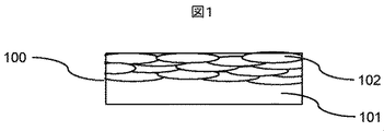
- FIG. 1 is a schematic diagram showing a surface parallel to the film thickness direction of a lead-acid battery current collector.
- the current collector 100 includes a base material 101 as a core material and a coating 103 made of lead or lead alloy powder 102.
- the lead or lead alloy powder 102 has a flat shape with a small dimension in a direction parallel to the film thickness direction.
- the lead alloy powder used for the current collector contains 0.1 to 10 wt%, preferably 0.2 to 5.0 wt%, of at least one element selected from the group consisting of Sn, Sb, Ca, Ag, Ba, and Sr.
- FIG. 2 is a schematic view showing a surface perpendicular to the film thickness direction of the lead-acid battery current collector, and shows a view of the coating film as seen from the deposition direction of the particles 102.
- the lead or lead alloy particles 102 have little vertical and horizontal dimensional differences and a low flatness.
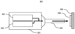
- Fig. 3 shows a conceptual diagram of the cold spray device.
- the current collector 100 can be manufactured by a cold spray process.
- the cold spray apparatus 300 includes a chamber 303 having a powder supply unit 301 and a heated gas supply unit 302, and a nozzle 304.
- the cold spray process is a non-melting process in which a powder charged into a pressurized gas stream is collided and deposited on a substrate 305 to form a coating 306. Since the powder does not melt and collides and accumulates in the solid phase, it is work hardened to form a dense coating with high hardness.
- FIG. 4 is a schematic diagram showing a film formation process by a cold spray apparatus.
- the coating 401 is formed by depositing lead or lead alloy powder 402. Since the powder is relatively soft and accumulates while deforming when colliding with the base material 403, the thickness of the powder in the deposition direction is small.
- the cold spray process powder is sprayed onto the substrate at high speed through a compressed gas (atmosphere, nitrogen, helium, etc.) and deposited.
- the substrate shape is not particularly limited, and it can be deposited only at a necessary portion. Compared with the conventional rolling process, it is not necessary to significantly shape the film after forming the film, so that the amount of scrap can be reduced.
- Lead is a metal with a low melting point, and crystal grains are coarsened by heat treatment such as casting and sintering, or particles are easily bonded to form coarse grains. Coarse crystal grains deteriorate the characteristics of the lead storage battery such as corrosion resistance.
- the cold spray process is a non-melting process and can reduce grain coarsening and oxidation.
- lead and lead alloys are metals that are easily plastically deformed, they can be deposited on the substrate relatively easily in the cold spray process. Moreover, since the raw material is powder, an oxide film is formed on the powder surface. When the powder forms a film, the oxide film or oxide on the surface of the powder is taken into the film, thereby suppressing recrystallization of the crystal grains. That is, it is possible to form a film in which coarsening of crystal grains hardly occurs.
- Lead powder and lead alloy powder are plastically deformed by colliding with the surface of the substrate at a high speed, and the aspect ratio in the plane parallel to the deposition direction is in the range of about 1: 2 to 1:10.
- the particles having such an aspect ratio are desirably 60% or more. If it is 60% or more, the corrosion path at the time of intergranular corrosion becomes short, and high corrosion resistance can be obtained.
- the aspect ratio in the plane perpendicular to the deposition direction is generally in the range of 1: 1 to 1: 3.
- the particles having such an aspect ratio are desirably 60% or more. If it is 60% or more, the structure anisotropy becomes weak and the strength hardly varies. Therefore, even if an oxide grows on the coating during the progress of corrosion, the coating is not easily broken, and as a result, the corrosion resistance is improved.
- the shape of the base material as a core material is not limited.
- a foil, a plate shape, or a shape previously processed into a lead-acid battery current collector shape, that is, a lattice shape may be used.
- the base material that is the core material is preferably conductive and has corrosion resistance to sulfuric acid that is an electrolytic solution.
- Example Nos. 1 to 3 produced by cold spray and Comparative Examples No. 4 to 5 produced by a conventional casting and rolling process were prepared. Each test piece was cut into a rectangular parallelepiped shape including a base material and a coating. Comparative Examples No. 4 and No. 5 were cut out by changing the sampling direction of the specimen.
- a 14-cycle corrosion resistance test was conducted with 10 mA / cm 2 being charged in a sulfuric acid electrolysis solution having a specific gravity of 75 ° C. and a specific gravity of 1.28 (20 ° C.) for 6 hours and allowed to stand for 6 hours.
- the cross section of the specimen after the corrosion resistance test was observed with a laser microscope, the intergranular corrosion depth was measured, and the corrosion depth (%) relative to the specimen thickness before the corrosion test was determined.
- pure lead coatings were formed on both sides of the pure lead plate by a cold spray process.
- the cold spray device used a low pressure type device, and the gas used was compressed air.
- the gas temperature was appropriately adjusted between room temperature and 100 ° C. and gas pressure between 0.6 and 1 MPa.
- the pure lead powder for forming the coating had an average particle size of about 20 ⁇ m.
- lead alloy powder (Pb-1.6Sn-0.05Ca) having an average particle size of about 40 ⁇ m was deposited on a pure lead plate.
- Cold spray conditions are the same as No.1.
- FIG. 5 is a schematic view of Example No. 3 as seen from a plane parallel to the film thickness direction of the film. A coating 502 was formed around the entire base material 501 around the base material 501.
- the structure of the surface parallel to the film thickness direction of No. 2 is that the lead alloy powder is deformed into a flat shape, and in about 60% of the alloy powder, the aspect ratio of the particles parallel to the film thickness direction is 1: 2 to It was in the range of 1:10.
- the number of particles with an aspect ratio of 1: 2 to 1:10 is less because the hardness of lead alloy powder is higher than that of pure lead. This is because the amount is small.
- the aspect ratio was in the range of 1: 1 to 1: 3.
- Examples No. 1 and No. 2 and Comparative Example No. 4 were 3 to 4 kgf / mm 2
- Comparative Example No. 4 was about 1 to 2 kgf / mm 2
- the example had higher strength.
- the powder was deposited by the cold spray process, which is a non-melting process
- the structure does not become coarse due to heat, so it becomes a dense structure, and since it is collided with the substrate at a high speed, it is hardened by work hardening. It was also expensive.
- No. 2 contains Ca and Sn to increase the strength.
- Table 1 shows the corrosion resistance test results.
- the corrosion depth was large and large cracks were generated, and the corrosion depth was about 36%.
- the corrosion depth of the example was about 7 to 8%, which is more corrosive than the comparative example. The depth was small and intergranular corrosion did not progress.
- the lead-acid battery current collectors of the examples have higher strength and superior corrosion resistance than those of the comparative examples.
Landscapes
- Chemical & Material Sciences (AREA)
- Chemical Kinetics & Catalysis (AREA)
- Electrochemistry (AREA)
- General Chemical & Material Sciences (AREA)
- Engineering & Computer Science (AREA)
- Materials Engineering (AREA)
- Cell Electrode Carriers And Collectors (AREA)
Abstract
被膜の強度を向上させることで、耐食性を向上させる。導電性を有する基材と、前記基材を被覆する被膜とを備えた集電体において、前記被膜は鉛を含む粒子が堆積して形成され、前記被膜表面における前記粒子の60%以上が、被膜を形成する粒子が基材上に堆積する方向に垂直な面においてアスペクト比1:1~1:3 である。また、導電性を有する基材に、前記基材を被覆する被膜を形成した集電体の製造方法において、ガスを加圧する工程と、加圧された前記ガス中に鉛を含む粒子を投入する工程と、前記粒子を前記基材に噴霧する工程とを備える。
Description
本発明は、集電体、鉛蓄電池、集電体の製造方法に関する。
鉛蓄電池は二次電池の一つであり、コスト面に優れていることから、非常用電源や風力・太陽光発電用蓄電池、また自動車用バッテリー、フォークリフト等電動車用電源として広く使用されている。このような様々な目的・用途に対応するため、鉛蓄電池には更なる長寿命化、高信頼性が求められている。
耐食性を向上させる集電体として、特許文献1には、アトマイズ鉛粉末と鉛酸化物を圧延して作製した集電体が記載されている。これらの鉛又は鉛合金の組織は、圧延方向に伸びた形状の組織となっている。このため、粒界腐食時の腐食進行パスを長くすることが可能となるため、耐食性を向上させることが可能となる。更に、アトマイズ鉛粉末に混合された鉛酸化物が、鉛合金の再結晶化を抑制するため、結晶粒の粗大化が抑制され、耐食性のみならず機械的特性も向上することが記載されている。
集電体表面は、電解液と接触することで腐食が進行し、集電体表面に酸化物が成長する。酸化物の成長により、集電体表面には引張応力がランダムな方向に発生する。上記特許文献のように、電解液に接している面から見て、被膜を形成する粒子のアスペクト比が特定の方向に大きいと、引張応力に対して強度に異方性が生じ、被膜の強度が低下するという課題があり、耐食性について十分考慮されていない。
本発明の目的は、耐食性を向上させることである。
上記目的を達成するために、本発明は、導電性を有する基材と、前記基材を被覆する被膜とを備えた集電体において、前記皮膜は鉛を含む粒子が堆積して形成され、膜圧方向に垂直な面における前記粒子の60%以上がアスペクト比1:1~1:3であることを特徴とする。
また、導電性を有する基材に、前記基材を被覆する被膜を形成した集電体の製造方法において、ガスを加圧する工程と、加圧された前記ガス中に鉛を含む粒子を投入する工程と、前記粒子を前記基材に噴霧する工程とを備えることを特徴とする。
本発明により、耐食性を向上させることができる。
以下、本発明の実施形態について。図面を用いて説明する。
鉛蓄電池用集電体は、芯材となる基材上に、鉛粉又は鉛合金粉からなる被膜を有するものである。本発明では、被膜を形成する粒子が基材上に堆積する方向を膜厚方向と称する。膜厚方向に垂直な面において、アスペクト比1:1~1:3である粒子が60~100%を占める。これは、被膜を膜厚方向に垂直などの面で切りだしても、上記のアスペクト比となる粒子の合計面積が60%以上であることを示す。この構成によれば、被膜を膜厚方向から見た場合に細長い粒子が少なく、粒子の扁平度を小さくすることができる。即ち、電解液と接触する被膜表面における粒子が特定の方向性を持たず、この面内ではどの方向も同等の強度を有することになる。従って、腐食が進行して発生する引張応力に対する抵抗力も異方性が小さく、面内のどの方向にも同等の抵抗力を持つので、被膜の強度が向上し、集電体の耐食性が向上する。
上記構成に加えて、膜厚方向に平行な面において、アスペクト比1:2~1:10である粒子が60~100%を占めるようにすることが好ましい。これにより、膜厚方向に平行な面において、粒子の粒径は扁平形状となる。このような扁平形状となることにより、粒界で腐食が進行する時に、被膜表面から芯材へ向かう腐食パスが長くなることから、耐食性が向上する。
図1は、鉛蓄電池用集電体の膜厚方向に平行な面を示す模式図である。集電体100は、芯材である基材101と、鉛又は鉛合金粉102からなる被膜103で構成されている。鉛又は鉛合金粉102は、膜厚方向に平行な方向の寸法が小さい扁平状となっている。
集電体に用いる鉛合金粉は、Sn、Sb、Ca、Ag、Ba、Srからなる群より選択される少なくとも1種の元素を0.1~10wt%、好ましくは0.2~5.0wt%含有する。
図2は、鉛蓄電池用集電体の膜厚方向に垂直な面を示す模式図であり、被膜を粒子102の堆積方向から見た図を示す。鉛又は鉛合金粒子102は、縦横の寸法差があまりなく、扁平度が小さくなっている。
図3はコールドスプレー装置の概念図を示す。集電体100は、コールドスプレープロセスにより作製することが可能である。コールドスプレー装置300は、粉末供給部301及び加熱ガス供給部302を備えたチャンバ303と、ノズル304で構成されている。コールドスプレープロセスは、加圧されたガス流の中へ投入された粉末を、基材305に衝突・堆積させて被膜306を形成する非溶融プロセスである。粉末は溶融せず、固相のまま衝突・堆積するので、加工硬化して硬度が高く緻密な被膜が形成される。
図4は、コールドスプレー装置による被膜の形成過程を示す模式図である。被膜401は鉛又は鉛合金粉402が堆積して形成される。粉末は比較的軟らかく、基材403に衝突する際に変形しながら堆積していくため、粉体の堆積方向の厚さが小さくなっている。
コールドスプレープロセスは、圧縮気体(大気、窒素、ヘリウム等)を介して粉体を基材上に高速で噴射し、堆積される。基材形状は特に限定されることはなく、必要な個所へのみ堆積させることが可能である。従来の圧延プロセスと比較して、被膜形成後に大幅に形状加工する必要がないので、スクラップの量を低減することができる。
鉛は融点が低い金属であり、鋳造や焼結等の熱処理により結晶粒が粗大化したり、粒子同士が結合して粗大粒になりやすい。粗大な結晶粒は、耐食性など鉛蓄電池の特性を低下させる。コールドスプレープロセスは、非溶融プロセスであり、結晶粒の粗大化、及び酸化を低減することが可能である。
鉛及び鉛合金は塑性変形しやすい金属であることから、コールドスプレープロセスでは、比較的容易に基材へ堆積させることが可能である。また原料が粉末であるため、粉末表面には酸化被膜が形成されている。粉末が被膜を形成する際に、粉末表面の酸化被膜や酸化物が被膜中に取り込まれることで、結晶粒の再結晶化を抑制する。つまり結晶粒の粗大化が起こりにくい被膜を形成することができる。
鉛粉及び鉛合金粉は、基材の表面に高速で衝突することにより、塑性変形し、堆積方向に平行な面におけるアスペクト比が概ね1:2~1:10の範囲となる。このようなアスペクト比を有する粒子は60%以上であることが望ましい。60%以上では、粒界腐食時における腐食パスが短くなり、高耐食性を得ることができる。
更に堆積方向に垂直な面におけるアスペクト比は概ね1:1~1:3の範囲となる。このようなアスペクト比を有する粒子は60%以上であることが望ましい。60%以上では、組織異方性が弱くなり、強度にばらつきが生じにくい。従って、腐食進行時に被膜に酸化物が成長しても、被膜が破断されにくくなり、結果として耐食性が向上する。
コールドスプレープロセスは、ノズル位置又は基材を移動しながら被膜を形成することが可能であるため、芯材となる基材形状は限定されない。芯材となる基材は、箔、板状、あるいは予め鉛蓄電池用集電体の形状、即ち格子形状に加工したものを使用してもよい。また、芯材となる基材は、導電性を有し、電解液である硫酸に対して耐食性を有するものが望ましく、鉛又は鉛合金、導電性を有するTi、導電性樹脂、導電性セラミック、又はこれらの表面を導電性物質でコーティングしたものを用いることができる。
また、鉛蓄電池用集電体の他、集電端子ポール、ストラップなどへ用いることができる。
以下、実施例及び比較例について説明する。なお、本発明は、これらの実施例に限定されるものではない。
引張強さを評価する試験片として、コールドスプレーにより作製した実施例No.1~3と、従来の鋳造圧延プロセスにより作製した比較例No.4~5を準備した。何れの試験片も、基材と被膜を含む直方体の形状に切り出した。比較例No.4とNo.5は、試験片の採取方向を変えて切りだした。75℃、比重1.28(20℃)の硫酸電界液中で10mA/cm2を6時間充電、6時間放置することを1サイクルとして、14サイクルの耐食性試験を実施した。耐食性試験後の試験片断面をレーザー顕微鏡により観察し、粒界腐食深さを測定し、腐食試験前の試験片厚さに対する腐食深さ(%)を求めた。
No.1は、純鉛の板材の両面へコールドスプレープロセスにより、純鉛の被膜を形成した。コールドスプレー装置は低圧型装置を使用し、ガスは圧縮空気を用いた。ガス温度は室温~100℃、ガス圧力0.6~1MPaの間で適宜調整した。被膜を形成するための純鉛の粉末は、平均粒径約20μmのものを用いた。
No.2は、純鉛の板材へ、平均粒径約40μmの鉛合金粉(Pb-1.6Sn-0.05Ca)を堆積させた。コールドスプレー条件は、No.1と同様である。
No.3は、純鉛の板材を穴あけ加工し、格子形状とした基材へ、平均粒径約20μmの純鉛粉の被膜を形成した。コールドスプレー条件は、No.1と同様であるが、基材及びコールドスプレー装置のノズルを適宜回転させながら、基材の格子部全周囲へ鉛粉を堆積させた。図5は、実施例No.3を被膜の膜厚方向に平行な面からみた模式図である。基材501を中心として、基材の全周囲に被膜502を形成した。
コールドスプレープロセスにより作製したNo.1~3について、組織観察用の試験片を切り出し、膜厚方向(堆積方向)に平行な面、及び膜厚方向に垂直な面の組織を観察した。No.1の膜厚方向に平行な面の組織は、鉛粉が扁平状に大きく変形しており、膜厚方向に垂直な面の組織とは形状が大きくなっていた。堆積粒子のうち98%が膜厚方向に平行な面において、1:2~1:10のアスペクト比であった。膜厚方向に垂直な面においては、扁平状に変形した鉛粉がほとんど観察されず、アスペクト比は1:1~1:3の範囲にあり、等方組織であった。
No.2の膜厚方向に平行な面の組織は、鉛合金粉が扁平状に変形し、約60%の合金粉において、膜厚方向に平行な面における粒子のアスペクト比が1:2~1:10の範囲にあった。No.1と比較して、アスペクト比1:2~1:10の範囲にある粒子が少ないのは、鉛合金粉の硬度が純鉛よりも高いため、基材へ衝突・堆積する際の変形量が小さいためである。膜厚方向に垂直な面の組織からは、No.1と同様に、扁平状に変形した鉛合金粉はほとんど観察されず、アスペクト比は、1:1~1:3の範囲であった。
格子形状へ加工した基材へ被膜を形成したNo.3においても、No.1とほぼ同様の被膜組織が得られた。
なお、No.1~No.3で作製した被膜にはいずれも気孔は観察されず、緻密な被膜が形成された。
実施例No.1及びNo.2と比較例No.4の引張強さを測定したところ、実施例No.1及びNo.2は3~4kgf/mm2であるのに対し、比較例No.4は1~2kgf/mm2程度であり、実施例の方が高い強度を有していた。非溶融プロセスであるコールドスプレープロセスにより粉末を堆積させた実施例では、組織が熱により粗大化することがないため緻密な組織となり、更に高速で基材へ衝突させているため加工硬化により、強度も高くなった。特にNo.2は、Ca及びSnを含有していることにより、強度が増す。
表1は耐食性試験結果を示す。比較例では、腐食深さが大きく、かつ大きなクラックも発生し、腐食深さは約36%であったが、実施例の腐食深さは7~8%程度であり、比較例にくらべ、腐食深さが小さく、粒界腐食が進行していなかった。
以上より、実施例の鉛蓄電池用集電体は、比較例のものよりも強度が高く、耐食性に優れていることが分かる。

100 集電体
101 基材
102 鉛又は鉛合金粒子
300 コールドスプレー装置
301 粉末供給部
302 加熱ガス供給部
303 チャンバ
304 ノズル
305 基材
306 被膜
401 被膜
402 鉛又は鉛合金粉
403 基材
101 基材
102 鉛又は鉛合金粒子
300 コールドスプレー装置
301 粉末供給部
302 加熱ガス供給部
303 チャンバ
304 ノズル
305 基材
306 被膜
401 被膜
402 鉛又は鉛合金粉
403 基材
Claims (8)
- 導電性を有する基材と、前記基材を被覆する被膜とを備えた集電体において、前記皮膜は鉛を含む粒子が堆積して形成され、膜圧方向に垂直な面における前記粒子の60%以上がアスペクト比1:1~1:3であることを特徴とする集電体。
- 請求項1において、前記被膜は膜厚方向に平行な面における前記粒子の60%以上がアスペクト比1:2~1:10であることを特徴とする集電体。
- 請求項1において、前記粒子はSn、Sb、Ca、Ag、Ba、Srから選択される少なくとも1種を含むことを特徴とする集電体。
- 請求項1において、前記基材は鉛、鉛合金、Ti、導電性樹脂、導電性セラミックから選択される少なくとも1種を含むことを特徴とする集電体。
- 請求項1において、前記粒子はコールドスプレー法を用いて前記基材に堆積して形成されることを特徴とする集電体。
- 請求項1の集電体と、電解液とを備えた鉛蓄電池。
- 導電性を有する基材に、前記基材を被覆する被膜を形成した集電体の製造方法において、ガスを加圧する工程と、加圧された前記ガス中に鉛を含む粒子を投入する工程と、前記粒子を前記基材に噴霧する工程とを備えることを特徴とする集電体の製造方法。
- 請求項7において、前記基材が格子形状であることを特徴とする集電体の製造方法。
Priority Applications (2)
| Application Number | Priority Date | Filing Date | Title |
|---|---|---|---|
| JP2015504012A JPWO2014136168A1 (ja) | 2013-03-04 | 2013-03-04 | 集電体、鉛蓄電池、集電体の製造方法 |
| PCT/JP2013/055771 WO2014136168A1 (ja) | 2013-03-04 | 2013-03-04 | 集電体、鉛蓄電池、集電体の製造方法 |
Applications Claiming Priority (1)
| Application Number | Priority Date | Filing Date | Title |
|---|---|---|---|
| PCT/JP2013/055771 WO2014136168A1 (ja) | 2013-03-04 | 2013-03-04 | 集電体、鉛蓄電池、集電体の製造方法 |
Publications (1)
| Publication Number | Publication Date |
|---|---|
| WO2014136168A1 true WO2014136168A1 (ja) | 2014-09-12 |
Family
ID=51490737
Family Applications (1)
| Application Number | Title | Priority Date | Filing Date |
|---|---|---|---|
| PCT/JP2013/055771 Ceased WO2014136168A1 (ja) | 2013-03-04 | 2013-03-04 | 集電体、鉛蓄電池、集電体の製造方法 |
Country Status (2)
| Country | Link |
|---|---|
| JP (1) | JPWO2014136168A1 (ja) |
| WO (1) | WO2014136168A1 (ja) |
Cited By (4)
| Publication number | Priority date | Publication date | Assignee | Title |
|---|---|---|---|---|
| CN106373665A (zh) * | 2015-07-20 | 2017-02-01 | 三星显示有限公司 | 各向异性导电膜制造装置及制造方法 |
| JPWO2022168770A1 (ja) * | 2021-02-02 | 2022-08-11 | ||
| JP2023071228A (ja) * | 2021-11-11 | 2023-05-23 | 古河電池株式会社 | 液式鉛蓄電池 |
| US12431297B2 (en) | 2021-02-02 | 2025-09-30 | Murata Manufacturing Co., Ltd. | Electrolytic capacitor having an external electrode layer with a varying thickness and method for manufacturing the same |
Citations (3)
| Publication number | Priority date | Publication date | Assignee | Title |
|---|---|---|---|---|
| JPH05234596A (ja) * | 1992-02-21 | 1993-09-10 | Shin Kobe Electric Mach Co Ltd | 鉛蓄電池用格子 |
| JP2009064646A (ja) * | 2007-09-06 | 2009-03-26 | Shin Kobe Electric Mach Co Ltd | 鉛蓄電池 |
| JP2012064316A (ja) * | 2010-09-14 | 2012-03-29 | Sanyo Special Steel Co Ltd | Si系合金負極電極の製造方法 |
-
2013
- 2013-03-04 JP JP2015504012A patent/JPWO2014136168A1/ja active Pending
- 2013-03-04 WO PCT/JP2013/055771 patent/WO2014136168A1/ja not_active Ceased
Patent Citations (3)
| Publication number | Priority date | Publication date | Assignee | Title |
|---|---|---|---|---|
| JPH05234596A (ja) * | 1992-02-21 | 1993-09-10 | Shin Kobe Electric Mach Co Ltd | 鉛蓄電池用格子 |
| JP2009064646A (ja) * | 2007-09-06 | 2009-03-26 | Shin Kobe Electric Mach Co Ltd | 鉛蓄電池 |
| JP2012064316A (ja) * | 2010-09-14 | 2012-03-29 | Sanyo Special Steel Co Ltd | Si系合金負極電極の製造方法 |
Cited By (8)
| Publication number | Priority date | Publication date | Assignee | Title |
|---|---|---|---|---|
| CN106373665A (zh) * | 2015-07-20 | 2017-02-01 | 三星显示有限公司 | 各向异性导电膜制造装置及制造方法 |
| CN106373665B (zh) * | 2015-07-20 | 2020-03-27 | 三星显示有限公司 | 各向异性导电膜制造装置及制造方法 |
| JPWO2022168770A1 (ja) * | 2021-02-02 | 2022-08-11 | ||
| JP7683615B2 (ja) | 2021-02-02 | 2025-05-27 | 株式会社村田製作所 | 電解コンデンサ |
| US12327695B2 (en) | 2021-02-02 | 2025-06-10 | Murata Manufacturing Co., Ltd. | Electrolytic capacitor having an anode electrode with flat particles |
| US12431297B2 (en) | 2021-02-02 | 2025-09-30 | Murata Manufacturing Co., Ltd. | Electrolytic capacitor having an external electrode layer with a varying thickness and method for manufacturing the same |
| JP2023071228A (ja) * | 2021-11-11 | 2023-05-23 | 古河電池株式会社 | 液式鉛蓄電池 |
| JP7755975B2 (ja) | 2021-11-11 | 2025-10-17 | 古河電池株式会社 | 液式鉛蓄電池 |
Also Published As
| Publication number | Publication date |
|---|---|
| JPWO2014136168A1 (ja) | 2017-02-09 |
Similar Documents
| Publication | Publication Date | Title |
|---|---|---|
| KR101989219B1 (ko) | 강박 및 그 제조 방법 | |
| JP5567210B2 (ja) | 二次電池負極集電体用圧延銅箔およびその製造方法 | |
| KR100916436B1 (ko) | 리튬이온 이차전지용 음극 및 그것을 이용하는 리튬이온이차전지 | |
| KR101924250B1 (ko) | 이차전지 집전체용 압연 동박 및 그 제조방법 | |
| JP5264409B2 (ja) | リチウムイオン電池電極用アルミニウム合金箔およびその製造方法 | |
| JP6648088B2 (ja) | 二次電池負極集電体用圧延銅箔、それを用いた二次電池負極及び二次電池並びに二次電池負極集電体用圧延銅箔の製造方法 | |
| WO2013157598A1 (ja) | 鋼箔及びその製造方法 | |
| JP5507496B2 (ja) | 燃料電池セパレータの製造方法 | |
| JP2013108146A (ja) | 集電体用アルミニウム合金箔およびその製造方法 | |
| WO2018021360A1 (ja) | マグネシウム-リチウム合金及びマグネシウム空気電池 | |
| WO2014136168A1 (ja) | 集電体、鉛蓄電池、集電体の製造方法 | |
| TW201303938A (zh) | 鋁電解電容器用電極材及其製造方法 | |
| JP2013062047A (ja) | リチウムイオン二次電池用負極集電銅箔、リチウムイオン二次電池用負極、リチウムイオン二次電池及びリチウムイオン二次電池用負極集電銅箔の製造方法 | |
| JP5466669B2 (ja) | 燃料電池セパレータの製造方法 | |
| JP2000328159A (ja) | 銅合金箔 | |
| JP6058915B2 (ja) | 二次電池負極集電体用圧延銅箔又は圧延銅合金箔、それを用いたリチウムイオン二次電池用負極材及びリチウムイオン二次電池 | |
| CN113016095B (zh) | 锂离子电池集电体用轧制铜箔以及锂离子电池 | |
| JP2014032929A (ja) | 集電体用銅箔及びこれを用いたリチウムイオン二次電池用負極集電体 | |
| JP6331019B2 (ja) | 抵抗溶接用タングステン−モリブデン合金電極材料 | |
| JP2016018653A (ja) | 負極集電体、非水電解質電池用の負極及び非水電解質電池 | |
| JP2011040310A (ja) | リチウムイオン電池の負極活物質及び負極構造 | |
| CN112840422A (zh) | 铝电解电容器用电极材料的制造方法 | |
| CN116918050A (zh) | Al布线材料 | |
| KR20150056594A (ko) | 리튬 이온 전지용 정극 활물질, 리튬 이온 전지용 정극, 및, 리튬 이온 전지 | |
| JP2014060092A (ja) | 負極集電銅箔の製造方法、負極集電銅箔、リチウムイオン二次電池用の負極、及びリチウムイオン二次電池 |
Legal Events
| Date | Code | Title | Description |
|---|---|---|---|
| 121 | Ep: the epo has been informed by wipo that ep was designated in this application |
Ref document number: 13877314 Country of ref document: EP Kind code of ref document: A1 |
|
| NENP | Non-entry into the national phase |
Ref country code: DE |
|
| ENP | Entry into the national phase |
Ref document number: 2015504012 Country of ref document: JP Kind code of ref document: A |
|
| 122 | Ep: pct application non-entry in european phase |
Ref document number: 13877314 Country of ref document: EP Kind code of ref document: A1 |