WO2014133148A1 - 磁気ディスク用ガラス基板および磁気ディスク - Google Patents
磁気ディスク用ガラス基板および磁気ディスク Download PDFInfo
- Publication number
- WO2014133148A1 WO2014133148A1 PCT/JP2014/055114 JP2014055114W WO2014133148A1 WO 2014133148 A1 WO2014133148 A1 WO 2014133148A1 JP 2014055114 W JP2014055114 W JP 2014055114W WO 2014133148 A1 WO2014133148 A1 WO 2014133148A1
- Authority
- WO
- WIPO (PCT)
- Prior art keywords
- glass substrate
- center
- outer peripheral
- magnetic disk
- side wall
- Prior art date
- Legal status (The legal status is an assumption and is not a legal conclusion. Google has not performed a legal analysis and makes no representation as to the accuracy of the status listed.)
- Ceased
Links
Images



Classifications
-
- G—PHYSICS
- G11—INFORMATION STORAGE
- G11B—INFORMATION STORAGE BASED ON RELATIVE MOVEMENT BETWEEN RECORD CARRIER AND TRANSDUCER
- G11B5/00—Recording by magnetisation or demagnetisation of a record carrier; Reproducing by magnetic means; Record carriers therefor
- G11B5/62—Record carriers characterised by the selection of the material
- G11B5/73—Base layers, i.e. all non-magnetic layers lying under a lowermost magnetic recording layer, e.g. including any non-magnetic layer in between a first magnetic recording layer and either an underlying substrate or a soft magnetic underlayer
- G11B5/739—Magnetic recording media substrates
-
- G—PHYSICS
- G11—INFORMATION STORAGE
- G11B—INFORMATION STORAGE BASED ON RELATIVE MOVEMENT BETWEEN RECORD CARRIER AND TRANSDUCER
- G11B5/00—Recording by magnetisation or demagnetisation of a record carrier; Reproducing by magnetic means; Record carriers therefor
- G11B5/74—Record carriers characterised by the form, e.g. sheet shaped to wrap around a drum
- G11B5/82—Disk carriers
-
- G—PHYSICS
- G11—INFORMATION STORAGE
- G11B—INFORMATION STORAGE BASED ON RELATIVE MOVEMENT BETWEEN RECORD CARRIER AND TRANSDUCER
- G11B5/00—Recording by magnetisation or demagnetisation of a record carrier; Reproducing by magnetic means; Record carriers therefor
- G11B5/84—Processes or apparatus specially adapted for manufacturing record carriers
- G11B5/8404—Processes or apparatus specially adapted for manufacturing record carriers manufacturing base layers
Definitions
- the present invention relates to a glass substrate for a magnetic disk and a magnetic disk.
- a personal computer or a DVD (Digital Versatile Disc) recording device has a built-in hard disk device (HDD: Hard Disk Drive) for data recording.
- HDD Hard Disk Drive
- a hard disk device used in a portable computer such as a notebook personal computer
- a magnetic disk in which a magnetic layer is provided on a glass substrate is used, and the magnetic head slightly floats above the surface of the magnetic disk.
- magnetic recording information is recorded on or read from the magnetic layer.
- a glass substrate is preferably used because it has a property that it is less likely to be plastically deformed than a metal substrate (aluminum substrate) or the like.
- the density of magnetic recording has been increased.
- the magnetic recording information area is miniaturized by using a perpendicular magnetic recording method in which the magnetization direction in the magnetic layer is perpendicular to the surface of the substrate.
- the storage capacity of one disk substrate can be increased.
- a magnetic head equipped with a DFH (Dynamic Flying Height) mechanism is used to significantly shorten the flying distance from the magnetic recording surface, so that the recording / reproducing element of the magnetic head and the magnetic It is also practiced to increase the accuracy of recording / reproducing information (to improve the S / N ratio) by reducing the magnetic spacing between the magnetic recording layers of the disk. Even in this case, the surface irregularities of the substrate of the magnetic disk are required to be as small as possible in order to read and write magnetic recording information by the magnetic head stably over a long period of time.
- DFH Dynamic Flying Height
- Servo information used for positioning the magnetic head on the data track is recorded on the magnetic disk.
- the roundness of the end face on the outer peripheral side of the magnetic disk hereinafter also referred to as the outer peripheral end face
- the flying of the magnetic head is stabilized, the servo information can be read well, and the magnetic head can read and write.
- the technique described in Patent Document 1 discloses a glass substrate for a magnetic disk in which the roundness of the outer peripheral end face is 4 ⁇ m or less. According to this glass substrate, LUL (load-unload) test durability is improved by reducing the roundness of the outer peripheral end face.
- HDDs that employ a single write method in which recording is performed so that adjacent tracks partially overlap are known.
- signal deterioration due to recording on adjacent tracks is extremely small, so that the track recording density can be drastically improved.
- an extremely high track recording density of 500 kTPI (track per inch) or more can be realized.
- the improvement of TPI the followability of the magnetic head to the servo signal is required more severely than before.
- an HDD of 500 kTPI or more such as by adopting a single write method, even if the roundness of the outer peripheral end surface of the magnetic disk is reduced to 1.5 ⁇ m or less, the servo signal at the outer end of the magnetic disk is reduced.
- An object of the present invention is to provide a glass substrate for a magnetic disk and a magnetic disk that can prevent airflow from being disturbed near the outer peripheral end of the magnetic disk and suppress fluttering.
- the inventor makes play (magnetic disk) between the center of the magnetic disk and the center of the spindle.
- the HDD was assembled in a precise manner by eliminating the gap between the inner hole and the spindle.
- the blur in the disk radial direction of the outer peripheral end surface of the magnetic disk is made smaller than the circularity of the outer peripheral end surface, the roundness of the inner peripheral end surface of the magnetic disk, and the concentricity of the inner peripheral end surface and the outer peripheral end surface.
- fluttering was not improved.
- the contour line of the outer peripheral end portion that is the basis of roundness measurement reflects the shape that protrudes most outward from the substrate regardless of the shape of the outer peripheral end portion in the thickness direction.
- the conventional roundness measurement method does not reflect the three-dimensional shape in the thickness direction of the side wall surface of the outer peripheral end portion.
- the present inventor looks at the shape in the thickness direction of the magnetic disk in addition to the parameter in the direction parallel to the main surface of the magnetic disk such as the roundness, and first, at the outer peripheral side end of the magnetic disk The variation in thickness was examined, but the variation was extremely small and no problem was found. Therefore, the inclination and unevenness of the side wall surface (surface extending in the direction orthogonal to the main surface) and the chamfered surface (surface interposed between the side wall surface and the main surface) of the outer peripheral end surface of the magnetic disk are the outermost peripheral portion of the magnetic disk. It has been clarified that it has an influence on fluttering.
- the shape of the outer peripheral end face in the thickness direction affects fluttering by making the roundness of the outer peripheral end face of the magnetic disk extremely small.
- the distance between the center axis of the side wall surface on the outer peripheral side of the magnetic disk and the center of the two chamfered surfaces affects the size of fluttering.
- fluttering tends to increase as this distance increases.
- This distance is determined when the magnetic disk is viewed as a structure having a first cylinder having one axis and second and third cylinders having small diameters on both sides in the axial direction. It can be considered that it corresponds to the displacement of the axis of the cylinder. It is considered that the fluttering changes due to the eccentricity changing due to this axial shift.
- the glass substrate for a magnetic disk of the present invention is A glass substrate for a magnetic disk having a circular hole in the center and having a pair of main surfaces and end faces, The end surface has a side wall surface, and a chamfered surface interposed between the side wall surface and the main surface, The roundness of the outer peripheral end face is 1.5 ⁇ m or less,
- the contour lines in the circumferential direction are obtained at two positions separated by 200 ⁇ m in the plate thickness direction on the side wall surface on the outer peripheral side, and the midpoint between the centers of the two least-square circles obtained from these contour lines is the center.
- Point A One of the chamfered surfaces is obtained from the centers of the least-square circles obtained from the contours in the circumferential direction at the center positions of the lengths in the thickness direction on the two chamfered surfaces on the outer peripheral side.
- the center obtained from the center B is the center B and the center obtained from the other chamfer is the center C
- the total of the distance between the midpoint A and the center B and the distance between the midpoint A and the center C is 1 ⁇ m or less.
- the total is preferably 0.5 ⁇ m or less.
- the maximum height in the plate thickness direction is Rz (t)
- the maximum height in the circumferential direction is Rz (c).
- Rz (t) / Rz (c) is preferably 1.2 or less.
- the glass substrate for magnetic disk of the present invention is provided with measurement points every 30 degrees in the circumferential direction with respect to the center of the glass substrate, and the measurement of the shape of the portion between the side wall surface on the outer peripheral side and the chamfered surface.
- the difference in radius of curvature between adjacent measurement points is preferably 0.01 mm or less.
- the glass substrate for a magnetic disk of the present invention has a circumferential direction of the side wall surface at a plurality of different positions in the plate thickness direction including at least three positions separated by 100 ⁇ m intervals in the plate thickness direction on the side wall surface on the outer peripheral side.
- Each contour line is acquired, and an inscribed circle and a circumscribed circle in each contour line are acquired. It is preferable that a difference between the radius of the smallest inscribed circle and the radius of the largest circumscribed circle is 5 ⁇ m or less.
- the glass substrate for magnetic disk of the present invention is suitably used when the plate thickness is 0.5 mm or less.
- the magnetic disk of the present invention is a magnetic disk in which a magnetic layer is formed on the magnetic disk glass substrate.
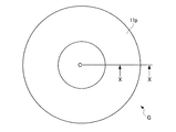
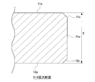
- the top view of the glass substrate for magnetic discs of this embodiment Sectional drawing of the plate
- Aluminosilicate glass, soda lime glass, borosilicate glass, or the like can be used as the material for the magnetic disk glass substrate in the present embodiment.
- aluminosilicate glass can be suitably used in that it can be chemically strengthened and a glass substrate for a magnetic disk excellent in the flatness of the main surface and the strength of the substrate can be produced.
- Amorphous aluminosilicate glass is more preferable because it can easily improve smoothness such as surface roughness.
- the composition of the glass substrate for a magnetic disk of this embodiment is not limited, the glass substrate of this embodiment is preferably converted to an oxide standard and expressed in mol%, SiO 2 is 50 to 75%, Al 2 to O 3 to 1 to 15%, at least one component selected from Li 2 O, Na 2 O and K 2 O in total 5 to 35%, selected from MgO, CaO, SrO, BaO and ZnO 0-20% in total of at least one component, and at least one selected from ZrO 2 , TiO 2 , La 2 O 3 , Y 2 O 3 , Ta 2 O 5 , Nb 2 O 5 and HfO 2 An amorphous aluminosilicate glass having a composition having a total of 0 to 10% of components.
- the glass substrate of the present embodiment is preferably, for example, in terms of mass%, SiO 2 is 57 to 75%, Al 2 O 3 is 5 to 20% (however, the total amount of SiO 2 and Al 2 O 3 is 74% or more), ZrO 2 , HfO 2 , Nb 2 O 5 , Ta 2 O 5 , La 2 O 3 , Y 2 O 3 and TiO 2 in total exceed 0%, 6% or less, Li 2 O 1 %, 9% or less, Na 2 O 5 to 28% (where the mass ratio Li 2 O / Na 2 O is 0.5 or less), K 2 O 0 to 6%, MgO 0 to 4% , CaO exceeds 0% and 5% or less (however, the total amount of MgO and CaO is 5% or less and the content of CaO is larger than the content of MgO), and SrO + BaO is 0 to 3% An amorphous aluminosilicate glass having a composition may be used.
- the glass substrate of this embodiment is, for example, SiO 2 : 45.60 to 60%, Al 2 O 3 : 7 to 20%, and B 2 O 3 : 1.00 to 8 in mass% based on oxide. %, And P 2 O 5 : 0.50 to 7%, and TiO 2 : 1 to 15%, and the total amount of RO: 5 to 35% (where R is Zn and Mg), content of CaO 3.00% or less, the content of BaO is equal to or less than 4%, PbO component, As 2 O 3 component and Sb 2 O 3 component and Cl -, NO -, SO 2- , F - component
- the main crystal phase contains RAl 2 O 4 , R 2 TiO 4 , where R is one or more selected from Zn and Mg, and the crystal grain size of the main crystal phase Is in the range of 0.5 nm to 20 nm, and the crystallinity is 15% or less It may be crystallized glass characterized by having a specific gravity of 2.95 or less.
- the composition of the glass substrate for a magnetic disk according to the present embodiment includes, as an essential component, at least one alkaline earth metal selected from the group consisting of SiO 2 , Li 2 O, Na 2 O, and MgO, CaO, SrO, and BaO.
- the molar ratio of the CaO content to the total content of MgO, CaO, SrO and BaO (CaO / (MgO + CaO + SrO + BaO)) is 0.20 or less and the glass transition temperature is 650 ° C. or more. Also good.
- a glass substrate for a magnetic disk having such a composition is suitable for a glass substrate for a magnetic disk used for a magnetic disk for energy-assisted magnetic recording.
- the glass substrate for magnetic disk in this embodiment is an annular thin glass substrate.
- the size of the glass substrate for magnetic disks is not ask
- board thickness (0.635mm, 0.8mm, 1mm, 1.27mm etc.) of the glass substrate for magnetic discs mentioned in the following description is a nominal value, and an actual measurement value is a little thicker than that, or It may be thin.
- FIG. 1A and 1B show a glass substrate G for magnetic disk of this embodiment.
- FIG. 1A is a plan view of the glass substrate G for magnetic disks
- FIG. 1B is a cross-sectional view in the thickness direction of the glass substrate G for magnetic disks.
- a magnetic disk glass substrate G (hereinafter also referred to as “glass substrate G” as appropriate) has a circular hole in the center and includes a pair of main surfaces 11p and 12p and an end surface.
- the end surface has a side wall surface 11w and chamfered surfaces 11c and 12c interposed between the side wall surface 11w and the main surfaces 11p and 12p.
- the glass substrate G for magnetic disk of this embodiment has a roundness of the outer peripheral end face of 1.5 ⁇ m or less and a shape evaluation value (described later) of 1 ⁇ m or less.
- the roundness measurement method may be a known method. For example, by arranging a plate-like probe longer than the thickness of the glass substrate so as to face the outer peripheral end surface in a direction perpendicular to the main surface of the glass substrate, the contour line can be obtained by rotating the glass substrate in the circumferential direction. And the difference in radius between the inscribed circle and the circumscribed circle of the contour line can be calculated as the roundness of the glass substrate. For example, a roundness / cylindrical shape measuring device can be used for measuring the roundness.
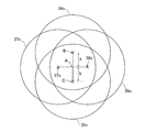
- FIGS. 2 and 3 are diagrams illustrating a method for measuring the shape evaluation value of the outer peripheral end face of the magnetic disk glass substrate G of the present embodiment.
- FIG. 2 shows a cross section in the plate thickness direction of the outer peripheral end face of the glass substrate G.
- the inclination angle of the side wall surface 11w is not particularly limited, and is, for example, 40 ° to 70 °.
- the boundary between the side wall surface 11w and the chamfered surfaces 11c and 12c is not limited to the shape having an edge as shown in the figure, and may be a curved surface that is smoothly continuous.
- the shape evaluation values are obtained by obtaining circumferential contour lines at two positions 37 and 38 separated by 200 ⁇ m in the plate thickness direction on the side wall surface 11w, respectively, and two least square circles 37c obtained from the contour lines, respectively.
- a midpoint between the centers 37o and 38o of 38c is defined as a midpoint A, and a contour line in the circumferential direction is formed at the center positions 34 and 35 of the plate thickness direction length on the two chamfered surfaces 11c and 12c.
- the center 34o obtained from one chamfered surface 11c is the center B and the center 35o obtained from the other chamfered surface 12c.
- the shape evaluation value of the glass substrate G is preferably 1.0 ⁇ m or less. More preferably, it is 0.5 ⁇ m or less.
- the two positions 37 and 38 on the side wall surface 11w are, for example, positions separated from the center position in the thickness direction of the glass substrate G by 100 ⁇ m toward the main surfaces 11p and 12p.
- the measurement positions 34 and 35 for acquiring the contour lines of the chamfered surfaces 11c and 12c are, for example, positions (for example, the surface of the glass substrate G) that approach the center position side in the plate thickness direction from the main surfaces 11p and 12p, respectively. When the length in the thickness direction of the chamfering surface is 0.15 mm, it is a position that approaches the central position by 0.075 mm from the main surfaces 11p and 12p of the glass substrate G).
- a roundness / cylindrical shape measuring device can be used as a measuring device for measuring the shape of the outer peripheral end face at each of the measurement positions 37, 38, 34, 35.
- the stylus 3 of the roundness / cylindrical shape measuring apparatus can be moved in the vertical direction (plate thickness direction) in units of microns. Prior to the measurement, the thickness of the glass substrate G is measured in advance with a micrometer.
- the contour shape measuring machine measures in advance the shape of the chamfered surface in the radial section, the length in the plate thickness direction and the radial direction, the angle with respect to the main surface, and the length of the side wall surface.
- the position of the boundary between the chamfered surface and the side wall surface can be determined by the intersection of the extended line of the side wall surface and the extended line of the chamfered surface when any of the outlines is linear.
- the contour line of the chamfered surface or the side wall surface has an arc shape, for example, it can be approximated by one circle that best overlaps the contour line, and can be determined by the intersection with the obtained circle.
- the contour line of the chamfered surface or the side wall surface is a combination of a straight line and an arc
- the boundary position may be determined by appropriately combining the above methods.
- the main surface of the glass substrate G is horizontal with the reference surface of the roundness / cylindrical measuring device, and further, the center of the glass substrate G is aligned with the rotation center of the measuring device, A glass substrate G is set in the measuring device. Then, the position of the tip of the stylus 3 that contacts the glass substrate G at the time of measurement is matched with the height of the upper main surface of the glass substrate G set in the measuring device. In this state, when the stylus 3 is lowered by half the thickness in the thickness direction, the stylus 3 is arranged at the center height of the thickness of the glass substrate G.
- the outline of the outer peripheral edge of the glass substrate G is measured at a point 37 where the stylus 3 is raised by 100 ⁇ m from the center of the plate thickness and a point 38 where the stylus 3 is lowered by 100 ⁇ m from the center of the plate thickness. From these contour lines, the centers 37o and 38o of the two least square circles 37c and 38c of the side wall surface 11w are determined, and further, the midpoint A between these two centers 37o and 38o is determined. Further, the position of the stylus 3 is set to be an intermediate height between the two chamfered surfaces in the respective plate thickness directions, and the contour line of the outer peripheral edge of the glass substrate G is measured at each of the positions 34 and 35.
- the centers B and C of the least squares 34c and 35c of the chamfered surfaces 11c and 12c are determined.
- the shape evaluation value is obtained by summing the distance a between the midpoint A and the center B and the distance b between the midpoint A and the center C.
- the intermediate positions 34 and 35 of the height in the plate thickness direction of the chamfered surface are the eccentricity of the cylinder corresponding to the chamfered surface portion when the structure having three cylinders having different diameters is considered. It is considered to be the point that best represents the degree.
- the position is considered to be the point that most affects the air flow in the vicinity of the chamfered surface. For these reasons, it is preferable to measure the contour line at this position.
- the shape evaluation values of the side wall surface 11w and the chamfered surfaces 11c and 12c are adjusted by, for example, a chamfering process using an overall grindstone, an end surface grinding process, and a brush polishing, which will be described later.
- the glass substrate G of this embodiment preferably has a cylindricity of the side wall surface 11w of 5 ⁇ m or less.
- the air flow between the HDD inner wall and the side wall surface is less likely to be disturbed, so fluttering can be further suppressed and the number of servo errors can be reduced.
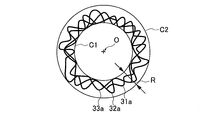
- FIG.4 and FIG.5 the cylindricity of the glass substrate G is demonstrated.
- 4 and 5 are diagrams for explaining a method of measuring the cylindricity of the side wall surface on the outer peripheral side of the magnetic disk glass substrate G of the present embodiment.
- the cylindricity is the contour line 31a in the circumferential direction of the side wall surface 11w at a plurality of different positions in the thickness direction including at least three positions 31, 32, 33 separated by 100 ⁇ m intervals in the thickness direction on the side wall surface 11w.
- 32a and 33a are acquired, the inscribed circle and the circumscribed circle in each contour line are acquired, and the difference R between the radius of the smallest inscribed circle C1 and the radius of the largest circumscribed circle C2 is referred to.
- the evaluation index is referred to as “cylindricity”.
- the measurement position 32 is, for example, the center position of the glass substrate G in the thickness direction.
- the measurement positions 31 and 33 are positions separated from the measurement position 32 by 100 ⁇ m in the thickness direction.
- the measurement positions 31 and 32 are provided at a position 100 ⁇ m away from the measurement position 32 in the thickness direction in the case of a glass substrate for a magnetic disk having a thickness of 0.635 mm.
- the distance in the plate thickness direction from the measurement position 32 to the measurement positions 31 and 32 may be changed.
- the distance may be set to 100 ( ⁇ m) ⁇ (L / 0.635).
- the contour lines 31a, 32a, and 33a can be distinguished and acquired at the measurement positions 31 to 33 of the side wall surface 11w. Is used. From this point, the stylus 3 of the measuring device preferably has a spherical surface with a radius of curvature of 0.4 mm or less.
- the stylus 3 is arranged so as to face each measurement position 31 to 33 of the measurement wall 11w of the glass substrate G, and the measurement is performed one by one in order.
- the outlines 31a to 33a of the measurement positions 31 to 33 are acquired by rotating the glass substrate G once in a state where the stylus 3 is arranged to face the measurement positions 31 to 33.
- an inscribed circle and a circumscribed circle are acquired based on the center obtained by the least square method, and the outermost circumscribed circle C2 and the innermost inscribed circle are obtained.
- a circle C1 is determined.
- a radius difference R between the circumscribed circle C2 and the inscribed circle C1 is obtained as the cylindricity of the side wall surface 11w.
- the cylindricity of the side wall surface 11w is adjusted by, for example, chamfering using an overall grinding wheel, end surface grinding, and brush polishing.
- Rz (t) / Rz ( c) is preferably 1.2 or less, and more preferably 1.1 or less.
- Rz (t) / Rz (c) exceeds the above range, the variation in the shape evaluation value for each substrate may increase during mass production. By making it within the above range, the variation of the shape evaluation value can be reduced.
- the surface roughness is measured by setting the wavelength band measured using a laser microscope, for example, from 0.25 ⁇ m to 80 ⁇ m, measuring the side wall surface 11w, and selecting a 50 ⁇ m square region within the measured range. It can be obtained by analysis.
- the surface roughness in the plate thickness direction and the circumferential direction is, for example, data obtained by measuring the line roughness from a plurality of cross sections corresponding to the respective directions in the plate thickness direction and the circumferential direction in a 50 ⁇ m square region. The average value of For example, five data may be acquired and set as the average value.
- the surface roughness of the outer peripheral side wall surface 11w is preferably 0.2 ⁇ m or less in terms of the maximum height Rz, and more preferably 0.1 ⁇ m or less.
- the surface roughness of the pair of chamfered surfaces 11c and 12c is more preferably within the above range for the same reason as described above.
- Rz mentioned above is the maximum height specified by JIS B0601: 2001.
- Ra is the arithmetic average roughness specified in JIS B0601: 2001.
- measurement points are provided every 30 degrees in the circumferential direction with respect to the center of the glass substrate G, and the radius of curvature at the measurement points of the shape of the portion between the side wall surface 11w and the chamfered surfaces 11c and 12c is determined.
- the difference in the radius of curvature between adjacent measurement points is preferably set to 0.01 mm or less.
- the number of measurement points is twelve.
- FIG. 6 is an enlarged view showing a part of a cross section on the outer peripheral side of the magnetic disk glass substrate G of the present embodiment.
- a first imaginary line L1 extending a straight portion of the chamfered surface 11c
- a second imaginary line L2 extending a straight portion of the side wall surface 11w
- a third imaginary line L3 passing through the first intersection P1 and extending perpendicularly to the straight portion of the chamfered surface 11c is set.
- an intersection between the portion between the side wall surface 11w and the chamfered surface 11c and the third virtual line L3 is defined as a second intersection P2.
- a first circle C1 having a predetermined radius (for example, 50 ⁇ m) with the second intersection P2 as the center is set.
- Two intersections between the portion between the side wall surface 11w and the chamfered surface 11c and the outer periphery of the first circle C1 are defined as a third intersection point P3 and a fourth intersection point P4, respectively.
- a second circle C2 passing through each of the second, third, and fourth intersections P2, P3, P4 is set.
- the curvature radius of the shape of the portion between the side wall surface 11w and the chamfered surface 11c is obtained.
- the radius of curvature of the shape of both the portion between the side wall surface and the chamfering surface adjacent to one main surface and between the side wall surface and the chamfering surface adjacent to the other main surface has been described above. You can stop it.
- the magnetic disk glass substrate G described above has extremely small roundness and shape evaluation values. For this reason, the airflow is hardly disturbed at the outer peripheral end, and fluttering is suppressed. Thereby, the followability to the servo information at the outer peripheral side end portion is improved.
- a high track recording density such as a magnetic disk adopting a single write method requires severe followability to servo information, but this glass substrate G can be suitably used for a magnetic disk.
- the reason why fluttering is suppressed due to the small shape evaluation value is considered as follows. When the roundness of the outer peripheral end of the glass substrate G is large, the amount of air pushed out by the outer peripheral end surface of the magnetic disk in the horizontal direction (radial direction) fluctuates.
- the air in the thickness direction flows smoothly and smoothly in the gap between the HDD inner wall and the outer peripheral end surface of the magnetic disk, and the fluttering level is low. It's hard to get bigger.
- the disturbance of the air flow inside the HDD is important for improving the followability of the magnetic head to the servo information.
- Such air turbulence increases fluttering.
- the present inventor has found that the outer peripheral end face of the glass substrate G causes a disturbance of the air flow that cannot be solved by a change in the design of the HDD, leading to a glass substrate G having a very small shape evaluation value of the outer peripheral end face. It was.
- the plate thickness of the glass substrate G of the present embodiment is, for example, 0.8 mm and 0.635 mm, and is, for example, 0.5 mm or less.
- the glass substrate G When the glass substrate G is used for a magnetic disk, it tends to flutter as the plate thickness decreases, and fluttering tends to increase.
- the glass substrate G has a shape evaluation value of 1 ⁇ m or less as described above, when it is used for a magnetic disk, the turbulence of the air flow at the outer peripheral end is suppressed, and fluttering is suppressed.
- the glass substrate G of the present embodiment has a very small shape evaluation value and the shape of the outer peripheral end surface is less likely to cause turbulence of the airflow.
- shape evaluation value is small, fluttering can be further suppressed when used for a magnetic disk. Thereby, the followability to the servo information of the magnetic head in the HDD is further improved.
- a magnetic disk having a magnetic recording layer with a track recording density of 500 kTPI (track per inch) or more such as a single write method or a magnetic disk for energy-assisted magnetic recording
- a magnetic disk having a magnetic recording layer with a track recording density of 500 kTPI (track per inch) or more such as a single write method or a magnetic disk for energy-assisted magnetic recording
- fluttering of the magnetic disk occurs.
- the followability to the servo information of the magnetic head of the HDD may be deteriorated, so that the glass substrate for a magnetic disk of this embodiment is suitable for the above-described magnetic disk having a high recording density.
- the evaluation index of the outer peripheral end portion on the main surface is 30 nm or less.
- the dove-off value is preferably greater than zero.
- the dub-off value is obtained by measuring the contour line between two points having a radius of 31.2 to 32.2 mm on the contour line of the main surface in the radial direction of the glass substrate G, and connecting the two points with a virtual straight line. The maximum distance from the virtual straight line to the contour line of the main surface of the glass substrate G.
- the dub-off value is expressed as a positive value when the virtual straight line is closer to the center in the thickness direction when the virtual straight line is compared with the contour of the main surface.
- the contour line of the main surface is on the center side of the plate thickness, it is represented by a negative value.
- this value is closer to 0, the shape of the main surface in the vicinity of the outermost periphery is flatter and better, and the magnetic head floats more stably. Therefore, in combination with the extremely small roundness and shape evaluation value, it is possible to suppress the fluctuation of the air flow at the outer peripheral edge of the substrate and reduce the fluttering variation to improve the yield of the HDD in mass production. it can.
- the dub-off value can be measured using, for example, an optical surface shape measuring device.
- the dub-off value of this case measures the area
- the nano surface (NW-Rq) of the main surface at the outer peripheral end of the main surface is preferably 0.5 mm or less.
- the nano waveness can be expressed by an RMS (Rq) value calculated as a roughness of a wavelength band of 50 to 200 ⁇ m in an annular region within a radius of 30.5 mm to 31.5 mm. It can be measured using a shape measuring machine. As a result, the roundness and the shape evaluation value are extremely small, and the fluctuation of fluttering is reduced by suppressing the disturbance of the air flow at the outer peripheral edge of the substrate, thereby improving the yield of HDD in mass production. Can do.
- a glass base plate is formed by press molding, and a process for forming an inner hole and an outer shape is appropriately performed to obtain a disk-shaped glass substrate having an inner hole with a predetermined plate thickness.
- a glass base plate can also be manufactured using well-known manufacturing methods, such as a float method, a downdraw method, a redraw method, a fusion method, not only these methods.
- circular shaped glass substrate is performed.
- the grinding process for the end surface of the glass substrate is performed in order to adjust the inner and outer diameters of the glass substrate and the formation of chamfered surfaces on the outer peripheral end and inner peripheral end of the glass substrate.
- the grinding process for the outer peripheral side end surface of the glass substrate may be, for example, a known chamfering process using a general-purpose grindstone using diamond abrasive grains. Grinding to the outer peripheral side end surface of the glass substrate according to the present embodiment is performed by combining the end surface of the glass substrate and the grindstone so that the trajectory of the grindstone contacting the end surface of the glass substrate is not constant in addition to grinding with the general-purpose grindstone. This is done with an additional grinding process.
- the additional grinding process with respect to the outer peripheral side end surface of a glass substrate is demonstrated below.
- the grinding wheel used for additional grinding of the outer peripheral side end surface of the glass substrate G is formed in a cylindrical shape as a whole and has grooves.
- the groove is formed so that both surfaces of the side wall surface 11w and the chamfered surface 11c on the outer peripheral side of the glass substrate G can be ground simultaneously.
- the groove exists on the side wall portion and both sides thereof. It has a groove shape consisting of chamfered parts.
- the side wall portion and the chamfered portion of the groove are formed in a predetermined dimensional shape in consideration of the finished target dimensional shape of the ground surface of the glass substrate G.
- the glass substrate G is inclined with respect to the groove direction of the grooves formed on the grinding wheel, that is, the rotation axis of the glass substrate G is set to the angle ⁇ with respect to the rotation axis of the grinding wheel.
- the grinding wheel is rotated by rotating both the glass substrate G and the grinding wheel while bringing the grinding wheel into contact with the outer peripheral side end surface of the glass substrate G.
- the trajectory of the grinding wheel that contacts the outer peripheral end surface of the glass substrate G does not become constant, and the abrasive grains of the grinding wheel contact and act on the substrate end surface at random positions, causing damage to the substrate. Therefore, the surface roughness and in-plane variation of the ground surface can be reduced, and the ground surface can be finished with a higher level of smoothness, that is, a quality level that can meet higher quality requirements. Furthermore, it also has the effect of improving the wheel life.
- the contact state between the grinding wheel and the glass substrate G becomes a surface contact state between the groove of the grinding wheel and the outer diameter arc of the glass substrate G, and the contact area between the grinding wheel and the glass substrate G increases. Therefore, the contact length (cutting edge length) of the grinding wheel with respect to the glass substrate G can be extended and the sharpness of the abrasive grains can be maintained. Therefore, stable grinding performance can be secured even when grinding is performed using a fine abrasive wheel that is advantageous for machining surface quality, and good grinding surface quality (mirror surface quality) by plastic mode-based grinding is stable. Can get to. In addition, by maintaining the sharpness of the grinding wheel and stably ensuring the grindability for realizing the plastic mode, it is possible to ensure good dimensional shape accuracy by chamfering the outer peripheral side end face of the glass substrate.
- the inclination angle ⁇ of the glass substrate G with respect to the groove direction of the grinding wheel described above can be arbitrarily set. However, in order to better exhibit the above-described effects, it is set within a range of 2 to 8 degrees, for example. preferable.
- the inclination angle ⁇ is preferably large in that the surface quality of the glass substrate G after grinding can be improved and the machining allowance of the outer peripheral side and inner peripheral side end surfaces of the glass substrate G by brush polishing can be reduced.
- the grinding wheel used for grinding is preferably a grinding stone (resin bond grinding stone) in which diamond abrasive grains are bonded with a resin (resin).
- the count of the diamond grindstone is preferably # 2000 to # 3000.
- a preferable example of the peripheral speed of the grinding wheel is 500 to 3000 m / min, and the peripheral speed of the glass substrate G is about 1 to 30 m / min.
- the ratio of the peripheral speed of the grinding wheel to the peripheral speed of the glass substrate G is preferably in the range of 50 to 300.
- the grinding process is divided into two times, and the first grinding is performed in a state where the rotation axis of the glass substrate G is inclined by the angle ⁇ as described above, and the second grinding is performed using another grindstone.
- Rz (t) / Rz (c) by adjusting the rotation axis of the glass substrate G by an angle of ⁇ and adjusting the second grinding allowance to be less than the first grinding allowance. Can be made 1.2 or less.
- the hardness (hereinafter referred to as “grinding wheel hardness”) of the binder (resin) portion on the surface of the resin bond grindstone measured by a nanoindentation test method using a Barcovic indenter under an indentation load condition of 250 mN is as follows. It is preferably within the range of 0.4 to 1.7 GPa.
- the grindstone hardness is an index correlated with the bond strength between diamond abrasive grains and resin.
- the inventors found that the bond strength between the diamond abrasive grains and the resin in the resin bond grindstone is as described above. It has been found that the shape evaluation value of the inner hole of the glass substrate after grinding is greatly affected. In other words, if the outer peripheral side end face is ground using a resin bond grindstone whose grinding wheel hardness is too high, the processing rate will be good, but the surface will be easily scratched, the outer shape evaluation value will deteriorate, and the grinding wheel hardness will be reduced.
- the shape evaluation value of the outer periphery of the glass substrate can be adjusted by changing the grindstone hardness.
- the above range is preferable as the range of the grindstone hardness.
- a method for measuring the hardness of the grindstone by the nanoindentation test method will be described.
- the binder part on the surface of the grinding wheel to be measured was loaded with a load of 1 nm / second using a square pyramid-shaped barkovic indenter, pressurized to 250 mN, and held for a predetermined time (for example, 10 seconds).
- the curve obtained here shows dynamic hardness characteristics, and shows characteristics closer to those in actual use than the hardness evaluation, which is a conventional static hardness characteristic. From the result of the obtained dynamic hardness characteristic curve, the grindstone hardness by the nanoindentation test method is obtained by the following formula (1).
- H F / Ac ...
- H the hardness of the grinding wheel
- F the load
- Ac the indentation area.
- the indentation area Ac is represented by the following relational expressions (2) and (3).
- Ac f (hc) ⁇ 24.5 ⁇ hc 2 Equation (2)
- hc hmax ⁇ ⁇ F / S Equation (3)
- hc depth of indentation
- hmax depth at maximum load
- hs depth of indentation at the start of unloading
- ho depth of indentation after unloading
- S proportional coefficient of load and displacement
- m inclination (dF / dh).
- circular shaped glass substrate is performed.
- the polishing process for the end surface of the glass substrate is performed in order to improve the surface properties on the outer peripheral side and inner peripheral side end surfaces (side wall surface and chamfered surface) of the glass substrate.
- the outer peripheral side and inner peripheral side end surfaces of the glass substrate are polished by brush polishing.
- the machining allowance of the glass substrate by brush polishing is set to such an extent that the side wall surface 11w and the surfaces of the chamfered surfaces 11c and 12c are in a mirror state.
- polishing main surface grinding
- polishing is given to the main surface of the ground glass substrate.
- the main surface of the glass substrate is polished using a double-side polishing apparatus equipped with a planetary gear mechanism.
- the double-side polishing apparatus has an upper surface plate and a lower surface plate. A flat polishing pad is attached to the upper surface of the lower surface plate and the bottom surface of the upper surface plate.
- One or more glass substrates accommodated in the carrier are sandwiched between the upper surface plate and the lower surface plate, and while supplying free abrasive grains containing an abrasive, either the upper surface plate or the lower surface plate is provided by the planetary gear mechanism.
- the main surfaces of the glass substrate can be polished by relatively moving the glass substrate and each surface plate.
- the upper surface plate is pressed against the glass substrate (that is, in the vertical direction) with a predetermined load
- the polishing pad is pressed against the glass substrate, and the glass substrate and the polishing pad.
- the polishing liquid is supplied.
- the main surface of the glass substrate is polished by the abrasive contained in the polishing liquid.
- the abrasive for example, known abrasive grains such as cerium oxide, zirconium oxide, and silicon dioxide can be used. In addition, you may divide and implement in several processes, changing the kind and size of an abrasive grain.
- polishing process may be chemically strengthened as needed.
- the chemical strengthening liquid for example, a molten liquid of a mixed salt of potassium nitrate and sodium sulfate can be used.
- a chemical strengthening process is implemented by immersing a glass substrate in a chemical strengthening liquid, for example.
- a chemical strengthening liquid for example.
- Second polishing (final polishing) step the glass substrate is subjected to second polishing.
- the second polishing for example, a polishing apparatus similar to the first polishing can be used.
- the difference from the first polishing is that the type and particle size of the free abrasive grains are different and the hardness of the resin polisher is different.
- the free abrasive grains used for the second polishing for example, fine particles such as colloidal silica made turbid in the slurry are used. Thereby, the surface roughness of the main surface of a glass substrate can further be reduced, and an edge part shape can be adjusted to a preferable range. Thus, a magnetic disk glass substrate is obtained.
- a magnetic disk is obtained as follows using a magnetic disk glass substrate.
- the magnetic disk is, for example, on the main surface of a glass substrate for magnetic disk (hereinafter simply referred to as “substrate”), in order from the closest to the main surface, at least an adhesion layer, an underlayer, a magnetic layer (magnetic recording layer), and a protection A layer and a lubricating layer are laminated.
- the substrate is introduced into a film forming apparatus that has been evacuated, and a film is sequentially formed from an adhesion layer to a magnetic layer on the main surface of the substrate in an Ar atmosphere by a DC magnetron sputtering method.
- a CoPt alloy can be used as the adhesion layer
- CrRu can be used as the underlayer.
- a CoPt alloy can be used. It is also possible to form a CoPt-based alloy and FePt based alloy L 10 regular structure and magnetic layer for heat-assisted magnetic recording.
- a magnetic recording medium can be formed by forming a protective layer using, for example, C 2 H 4 by a CVD method and subsequently performing nitriding treatment for introducing nitrogen into the surface. Thereafter, for example, PFPE (perfluoropolyether) is applied on the protective layer by a dip coating method, whereby a lubricating layer can be formed.
- PFPE perfluoropolyether
- the manufactured magnetic disk is preferably a magnetic disk drive device (HDD) as a magnetic recording / reproducing device, which includes a magnetic head equipped with a DFH (Dynamic Flying Height) control mechanism and a spindle for fixing the magnetic disk. (Hard Disk Drive)).
- HDD magnetic disk drive device
- DFH Dynamic Flying Height
- a 2.5-inch magnetic disk (outer diameter 65 mm, inner diameter 20 mm, plate thickness 0.635 mm, chamfered surface) The angle with respect to the main surface was 45 degrees).
- the shape of the chamfered surface in the radial cross section is linear, the angle with respect to the main surface is 45 degrees, the chamfered surface length in the thickness direction is 0.15 mm, and the chamfered surface has a radial length of 0. .15 mm.
- the composition of the glass of the produced magnetic disk glass substrate is as follows.
- Glass composition The SiO 2 63 mol%, the Al 2 O 3 10 mol%, the Li 2 O 1 mol%, the Na 2 O 6 mol%, MgO 19 mol%, the CaO 0 mol%, the SrO 0 mol%, BaO 0 mol%, ZrO 2 1 mol%
- the molar ratio of the CaO content to the total content of MgO, CaO, SrO and BaO (CaO / (MgO + CaO + SrO + BaO)) is 0, and the amorphous aluminosilicate glass has a glass transition temperature of 703 ° C.
- the glass substrate for magnetic disks of an Example it produced by performing each process of the manufacturing method of the glass substrate for magnetic disks of this embodiment in order.
- the glass substrate was formed by using a press forming method, forming inner holes and outer shapes by a known method, and adjusting the plate thickness.
- chamfering and side wall surface processing were performed on the inner periphery and outer peripheral side end surfaces of the glass substrate with a grinding wheel using diamond abrasive grains to form a chamfered surface and a side wall surface.
- the outer peripheral side end surface of the glass substrate is chamfered by adding a grinding process in which the end surface of the glass substrate and the grindstone are in contact with each other so that the trajectory of the grindstone contacting the end surface of the glass substrate is not constant.
- the surface quality was further improved while further improving the shape accuracy of the surface and the side wall surface.
- the additional grinding process on the outer peripheral side end face of the glass substrate was performed under the following grinding conditions using a resin bond grindstone of # 2500 diamond abrasive grains. At this time, the inclination angle of the glass substrate with respect to the groove direction of the grinding wheel (the aforementioned ⁇ ) was set to 5 degrees, and other conditions were appropriately adjusted.
- the glass substrate having a different shape evaluation value of the outer peripheral end face is obtained by appropriately adjusting the inclination angle ( ⁇ described above) and other factors (the grindstone count, the circumferential speed of the grindstone and the glass substrate) within the above-mentioned range. I made differently.
- ⁇ 5 degrees, but by further increasing the inclination angle, the surface quality after grinding can be improved, and the allowance for subsequent brush polishing can be reduced. Therefore, the shape evaluation value can be further improved.
- end face polishing step brush polishing was performed on the inner peripheral side end face and the outer peripheral side end face of the glass substrate using a slurry containing cerium oxide abrasive grains as polishing abrasive grains.
- the chamfering allowance in the end surface polishing step was appropriately adjusted according to the surface quality after the end surface grinding step.
- the main surface was ground using a known method, and then two-stage polishing and chemical strengthening were performed.
- a polishing liquid containing cerium oxide abrasive grains was used, and in the second polishing, a polishing liquid containing colloidal silica polishing abrasive grains was used.
- Chemical strengthening was performed before the second polishing.
- the glass substrate after polishing was cleaned using a known cleaning method as appropriate.
- the center of each least square circle of the contour line measured based on the two positions on the side wall surface is determined, the midpoint (A) obtained from these two centers, and the least square circle of the contour line of the chamfered surface
- the center (two of B and C) is viewed in plan from the thickness direction, the distance between A and B and the distance between A and C are obtained, and the value obtained by adding them is the shape evaluation value of the outer peripheral edge. did. All measurements were performed using a roundness / cylindrical measuring machine.
- the laser Doppler vibrometer receives the laser light reflected by the magnetic disk, and the amount of shake in the thickness direction of the magnetic disk is measured as a fluttering characteristic value.
- fluttering characteristic values were measured under the following conditions. ⁇ Environment of HDD and measurement system: Maintain the temperature at 25 ° C.
- a magnetic disk glass substrate (Comparative Example 3) having a roundness of 1.7 ⁇ m and a shape evaluation value of 0.5 ⁇ m was prepared, and fluttering characteristic values were measured using the glass substrate. 4. Accordingly, it can be seen that even when the shape evaluation value is 1.0 ⁇ m or less, the fluttering level is not improved when the roundness exceeds 1.5 ⁇ m.
- Example 1 10 glass substrates for magnetic disks of Example 1 were prepared, 10 glass substrates for magnetic disks of Examples 5 and 6 were prepared, and Rz, Ra, Rz (t) / Rz ( The average value of c) and the variation of the shape evaluation value were determined.
- the value of Rz was 0.2 ⁇ m or less for all glass substrates.
- the value of Ra was 0.02 ⁇ m or less for all glass substrates.
- the glass substrates for magnetic disks of Examples 5 and 6 were produced so that only the end face grinding process was different from the production conditions of Example 1. Specifically, in Examples 5 and 6, when grinding the outer peripheral side end face in the end face grinding step, the inclination angle of the glass substrate with respect to the groove direction of the grinding wheel (the aforementioned ⁇ ) is set to 5 degrees.
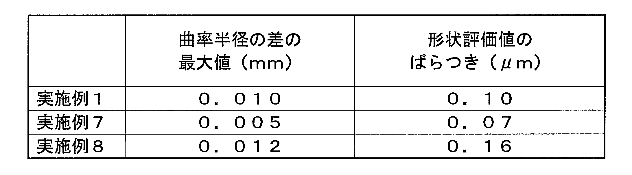
- Example 7 and 8 ten samples (Examples 7 and 8) with different end surface polishing allowances with respect to the production conditions of Example 1 were produced, and variations in shape evaluation values of Examples 7 and 8 were determined.
- the variation in the shape evaluation value is the difference between the maximum value and the minimum value of the 10 shape evaluation values, as shown in Table 2.
- the shape accuracy can be increased. That is, the difference in the radius of curvature at the measurement positions adjacent in the circumferential direction of the outer peripheral end can be reduced.
- the radius of curvature for one glass substrate was determined as follows. That is, a total of 24 points including 12 points on the front surface side and 12 points on the back surface side at the outer peripheral end were measured. Then, a difference in curvature radius between adjacent measurement points at 12 points on the front surface side (12 pieces of data) and a difference in curvature radius between adjacent measurement points on the back side 12 points (12 pieces of data) are obtained, The maximum value among the total of 24 data was defined as the maximum value of the radius of curvature of the glass substrate.
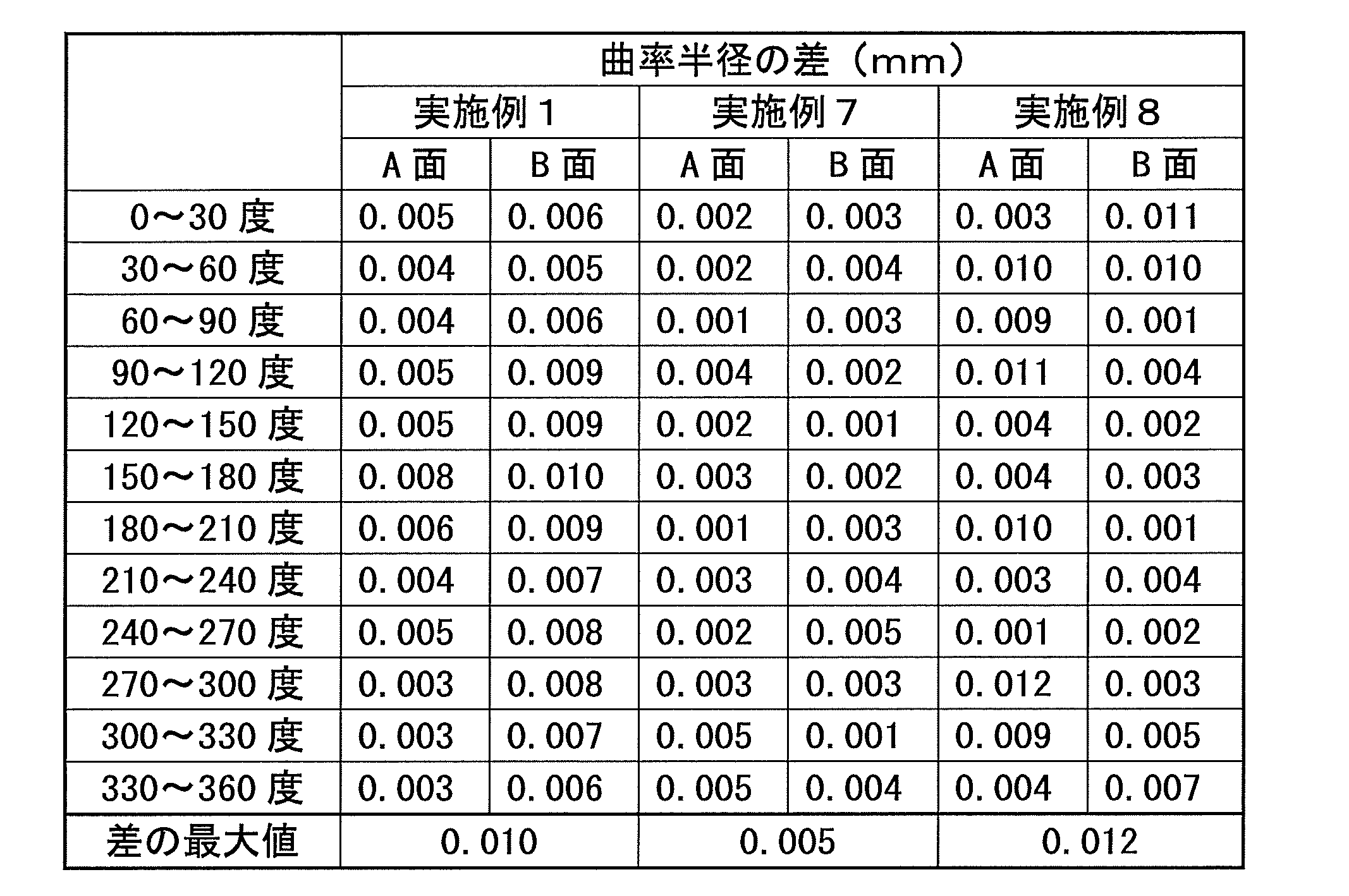
- Table 3 shows an example of measurement data. In Table 3, the front surface and the back surface of the glass substrate to be measured are shown as A surface and B surface, respectively.
- the difference in radius of curvature at “0 to 30 degrees” means the absolute value of the difference between the radius of curvature at the measurement point of 0 degrees and the curvature radius at the measurement point of 30 degrees. Further, for example, the back side of the 30-degree position on the A surface is set to the 30-degree position on the B surface.
- the maximum value of the difference in curvature radius was determined for each of the 10 samples of Examples 1, 7, and 8, all of the 10 samples of Example 1 were 0.010 mm or less. All of the samples were 0.005 mm or less, and all of the 10 samples of Example 8 were 0.012 mm or less.
- Table 3 The example of measurement data shown in Table 3 is data of one sample in which the maximum value of the difference in curvature radius is the largest for each example.
- Table 4 shows the maximum value of the difference in curvature radius (same as the value shown in Table 3; the largest value among the 10 sheets) and the variation in the shape evaluation value for Examples 1, 7, and 8. It can be seen from Table 4 that the variation in the shape evaluation value can be greatly reduced by setting the maximum value of the difference in curvature radius to 0.01 mm or less.
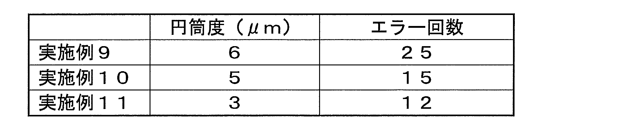
- samples (Examples 9 to 11) having different cylindricity were prepared by performing end face grinding using a resin bond grindstone having different grindstone hardness with respect to the production conditions of Example 1.
- cylindricity can be made small, so that grindstone hardness is made low.
- the measurement of cylindricity was calculated as shown in FIGS. That is, the center position in the thickness direction of the side wall surface and the contour line at a position 100 ⁇ m apart from the center position are obtained, the radius of the inscribed circle of the three contour lines is obtained, and then the three contour lines The difference between the maximum value and the minimum value of the inscribed circle radii was determined as the cylindricity of the side wall surface.
- Comparative Example 1A and Example 1A Two kinds of glass substrates having a thickness of 0.5 mm (the length of the outer peripheral side wall surface 0.3 mm) were prepared by appropriately changing the above processing conditions (Comparative Example 1A and Example 1A, respectively).
- the roundness and the shape evaluation value of Comparative Example 1A and Example 1A were made to be the same as Comparative Example 1 and Example 1, respectively.
- the improvement width from Comparative Example 1A to Example 1A was better than the improvement width from Comparative Example 1 to Example 1. Was big. Therefore, it was confirmed that the effect of the present invention is high particularly on a thin glass substrate having a thickness of 0.5 mm or less.
Landscapes
- Engineering & Computer Science (AREA)
- Manufacturing & Machinery (AREA)
- Magnetic Record Carriers (AREA)
- Manufacturing Of Magnetic Record Carriers (AREA)
Abstract
Description
さらに、記憶容量の一層の増大化のために、DFH(Dynamic Flying Height)機構を搭載した磁気ヘッドを用いて磁気記録面からの浮上距離を極めて短くすることにより、磁気ヘッドの記録再生素子と磁気ディスクの磁気記録層との間の磁気的スペーシングを低減して情報の記録再生の精度をより高める(S/N比を向上させる)ことも行われている。この場合においても、磁気ヘッドによる磁気記録情報の読み書きを長期に亘って安定して行うために、磁気ディスクの基板の表面凹凸は可能な限り小さくすることが求められる。
例えば、シングルライト方式を採用するなどして500kTPI以上としたHDDにおいて、磁気ディスクの外周端面の真円度を1.5μm以下に低減しても、磁気ディスクの外周側の端部ではサーボ信号の読み取りが不安定となる現象が生じていた。この現象は、磁気ディスクの外周側端部の最外周側では気流が乱れ、フラッタリングとよばれる磁気ディスクのばたつきが起きるために、安定した読み取りに影響が及ぶことが原因で生じると考えられる。磁気ディスクの主表面上の外周側端部は、それより内周側の領域と比べ、特にフラッタリングの影響をうけやすく、安定した読み取りが困難になる。
従来、磁気ディスクの真円度を小さくするとフラッタリングは少なくなり、真円度とフラッタリングの間には相関性があると考えられていた。しかし、本発明者の研究によれば、真円度を1.5μm以下にしても、フラッタリングは少なくならず、真円度が極めて小さい場合には、真円度とフラッタリングの間には相関性が見られないことが明らかとなった。
その理由は以下のように考えられた。すなわち、従来は、ガラス基板の板厚よりも長い板状のプローブをガラス基板の主表面に対して垂直方向に立てて外周端部に当てることで外周端部の真円度を測定していた。このとき、プローブは、板厚方向において最も基板の外側へ突出した位置で接する。したがって、真円度測定の基礎となる外周端部の輪郭線には、外周端部の板厚方向の形状とは無関係に、基板の外側へ最も突出した形状が反映されることになる。そのため、従来の真円度の測定方法では、外周端部の側壁面の板厚方向での3次元形状を反映したものとはなっていなかった。そして、従来の真円度の測定方法で磁気ディスクの外周端部の真円度を十分に良好にした場合には、真円度以外の別の要因がフラッタリングに及ぼす影響が相対的に大きくなり、それによって真円度とフラッタリングの間には相関性が見られなくなったと考えられた。
さらに研究を行った結果、磁気ディスクの外周側の側壁面の中心軸と2つの面取面の中心との距離がフラッタリングの大きさに影響を与えていることを突き止めた。つまり、この距離が大きくなると、フラッタリングが大きくなる傾向があることが分かった。この距離は、磁気ディスクを、一つの軸を有する第一の円筒と、その軸方向の両側に存在する径の小さい第二、第三の円筒とを有する構造体としてみた場合に、これら3つの円筒の軸のズレの大きさに相当すると考えることができる。この軸ズレにより偏心量が変化してフラッタリングが変化すると考えられる。
中心に円孔を有し、一対の主表面と端面とを備える磁気ディスク用ガラス基板であって、
前記端面は、側壁面と、前記側壁面と前記主表面の間に介在する面取面と、を有し、
外周側の端面の真円度が1.5μm以下であり、
外周側の側壁面上の板厚方向に200μm離れた2点の位置における円周方向の輪郭線をそれぞれ取得し、これら輪郭線からそれぞれ求められる2つの最小二乗円の中心間の中点を中点Aとし、
外周側の2つの面取面上の板厚方向長さの中心の位置において円周方向の輪郭線をそれぞれ取得し、これら輪郭線から求められる最小二乗円の中心のうち、一方の面取面から求められる中心を中心B、他方の面取面から求められる中心を中心Cとしたとき、
中点Aおよび中心B間の距離と、中点Aおよび中心C間の距離との合計が1μm以下であることを特徴とする。
本実施形態における磁気ディスク用ガラス基板の材料として、アルミノシリケートガラス、ソーダライムガラス、ボロシリケートガラスなどを用いることができる。特に、化学強化を施すことができ、また主表面の平坦度及び基板の強度において優れた磁気ディスク用ガラス基板を作製することができるという点で、アルミノシリケートガラスを好適に用いることができる。アモルファスのアルミノシリケートガラスとすると表面の粗さなど平滑性を高めやすくより好ましい。
磁気ディスク用ガラス基板G(以下、適宜「ガラス基板G」ともいう。)は、中心に円孔を有し、一対の主表面11p,12pと端面とを備える。端面は、側壁面11w、及び、側壁面11wと主表面11p,12pの間に介在する面取面11c,12cを有する。
側壁面11w上の2つの位置37,38は、例えば、ガラス基板Gの板厚方向の中心位置から100μmずつ主表面11p,12p側に離れた位置である。面取面11c,12cの輪郭線を取得するための測定位置34,35は、例えば、主表面11p,12pからそれぞれ板厚方向の中心位置側に等距離近づく位置(例えば、ガラス基板Gの面取面の板厚方向長さが0.15mmの場合、ガラス基板Gの主表面11p,12pから中心位置に0.075mmずつ近づく位置)である。
なお、測定に先立って、マイクロメータで予めガラス基板Gの板厚が測定される。また、輪郭形状測定機により、半径方向の断面における面取面の、形状、板厚方向および半径方向の各長さ、主表面に対する角度、さらに、側壁面の長さ、が予め測定される。面取面と側壁面との境界の位置は、いずれの外形線も直線状である場合は、側壁面の延長線と面取面の延長線との交点によって定めることができる。面取面や側壁面の外形線が円弧状である場合は、例えば、当該外形線と最もよく重なる1つの円で近似し、求めた円との交点によって定めることができる。面取面や側壁面の外形線が直線と円弧を組み合わせたような場合は、適宜上記方法を組み合わせて境界の位置を定めればよい。
測定の際には、ガラス基板Gの主表面が真円度・円筒形状測定装置の基準面と水平になるように、さらには、ガラス基板Gの中心が測定装置の回転中心と合うように、ガラス基板Gが測定装置にセットされる。そして、スタイラス3の先端の、測定時にガラス基板Gと接触する位置が、測定装置にセットされたガラス基板Gの上側の主表面の高さと合わせられる。この状態で、スタイラス3を、板厚の半分の距離を板厚方向に下げると、スタイラス3は、ガラス基板Gの板厚の中央の高さに配される。そして、スタイラス3を板厚の中央から100μm上げた点37、および、板厚の中央から100μm下げた点38において、ガラス基板Gの外周端部の輪郭線が測定される。これらの輪郭線から、側壁面11wの2つの最小二乗円37c,38cの中心37o,38oが決められ、さらに、これら2つの中心37o,38o間の中点Aが決められる。
また、スタイラス3の位置が、2つの面取面の、それぞれの板厚方向における中間の高さとなるよう設定され、それぞれの位置34,35でガラス基板Gの外周端部の輪郭線が測定される。これらの輪郭線に基づいて、面取面11c,12cの最小二乗円34c,35cの中心B,Cが決められる。次いで、中点Aおよび中心B間の距離aと、中点Aおよび中心C間の距離bとを合計することで、形状評価値が求められる。
なお、面取面の板厚方向の高さの中間の位置34,35は、前述の径の異なる3つの円筒を有する構造体を考えた場合に、面取面部分に相当する円筒の偏心の程度を最もよく表す点と考えられる。また、当該位置は、面取面近傍の空気の流れに最も多く影響を与える点であると考えられる。これらの理由から、当該位置で輪郭線を測定することが好ましい。
側壁面11wと面取面11c,12cの形状評価値は、例えば、後述する、総形砥石を用いた面取り加工、端面研削加工、およびブラシ研磨によって調節される。
図4及び図5を参照して、ガラス基板Gの円筒度について説明する。図4及び図5は、本実施形態の磁気ディスク用ガラス基板Gの外周側の側壁面の円筒度の測定方法を説明する図である。円筒度は、側壁面11wにおいて板厚方向に100μm間隔で離れた少なくとも3点の位置31,32,33を含む板厚方向で異なる複数の位置における側壁面11wの円周方向の輪郭線31a,32a,33aをそれぞれ取得し、それぞれの輪郭線における内接円と外接円とを取得し、最も小さい内接円C1の半径と、最も大きな外接円C2の半径との差Rをいう。なお、このような半径の差Rという評価指標がゼロに近いほど、外周端面の形状が幾何学的円筒に近いということが言えるため、この明細書では上記評価指標を「円筒度」という。図5は、ガラス基板Gの外周端面の円筒度の測定方法を説明する図である。
側壁面11w上の複数の測定位置は、本実施形態では3箇所ある。3つの測定位置31,32,33のうち、測定位置32は、例えば、ガラス基板Gの板厚方向の中心位置である。測定位置31,33は、測定位置32から板厚方向に100μm離れた位置である。なお、測定位置32から板厚方向に100μm離れた位置に測定位置31,32を設けるのは、0.635mmの板厚の磁気ディスク用ガラス基板の場合である。板厚が異なる場合には、測定位置32から測定位置31,32までの板厚方向の距離を変更してもよい。例えば、板厚がT(mm)の磁気ディスク用ガラス基板の場合には、当該距離を100(μm)×(L/0.635)としてもよい。
各測定位置31~33でのガラス基板Gの外周端面の形状を測定するための測定装置としては、側壁面11wの測定位置31~33において各輪郭線31a,32a,33aを区別して取得できるものが用いられる。この点から、測定装置のスタイラス3は、曲率半径が0.4mm以下の球面を有することが好ましい。測定の際には、スタイラス3は、ガラス基板Gの測定壁11wの各測定位置31~33に対向するよう配置され、一箇所ずつ順に測定を行う。
各測定位置31~33の輪郭線31a~33aは、スタイラス3を各測定位置31~33に対向して配置した状態で、ガラス基板Gを一周回転させることで取得される。そして、取得された3つの輪郭線31a~33aのそれぞれについて、最小二乗法で求めた中心に基づいて内接円と外接円が取得され、最も外側に接する外接円C2及び最も内側に接する内接円C1が決められる。これら外接円C2及び内接円C1の半径の差Rが、側壁面11wの円筒度として求められる。
側壁面11wの円筒度は、例えば、総形砥石を用いた面取り加工、端面研削加工、およびブラシ研磨によって調節される。
外周側の側壁面11wの表面粗さは、最大高さRzで0.2μm以下であることが好ましく、0.1μm以下であるとさらに好ましい。また、算術平均粗さRaで0.02μm以下であることが好ましい。この範囲内とすることで、異物の付着や噛み込みによるサーマルアスペリティ障害の発生の防止や、ナトリウムやカリウム等のイオンの析出によるコロージョンの発生を防止することができる。また、一対の面取面11c,12cの表面粗さについても上記範囲内であると、上記と同様の理由でより好ましい。上述したRzとは、JIS B0601:2001で規定される最大高さのことである。Raとは、JIS B0601:2001で規定される算術平均粗さのことである。
先ず、一の測定点におけるガラス基板の板厚方向断面において、面取面11cの直線部を延ばした第1の仮想線L1と、側壁面11wの直線部を延ばした第2の仮想線L2との交点を第1の交点P1とする。次に、この第1の交点P1を通り、且つ、面取面11cの直線部に対して垂直に延びる第3の仮想線L3を設定する。次いで、側壁面11wと面取面11cとの間の部分と、第3の仮想線L3との交点を第2の交点P2とする。また、磁気ディスク用ガラス基板Gの断面において、第2の交点P2を中心として所定の半径(例えば50μm)を有する第1の円C1を設定する。また、側壁面11wと面取面11cとの間の部分と、第1の円C1の外周との2つの交点をそれぞれ第3の交点P3、第4の交点P4とする。さらに、第2、第3、第4の各交点P2,P3,P4のそれぞれを通る第2の円C2を設定する。そして、第2の円C2の半径Rをもとめることによって、側壁面11wと面取面11cとの間の部分の形状の前記曲率半径がもとめられる。
なお、側壁面と一方の主表面に隣接する面取面との間、及び、側壁面と他方の主表面に隣接する面取面との間の両方の部分の形状の曲率半径について、上述したようにしてもとめることができる。
形状評価値が小さいことによりフラッタリングが抑制される理由は、次のように考えられる。ガラス基板Gの外周端部の真円度が大きい場合は、磁気ディスクの外周端面が水平方向(半径方向)に押し出す空気の量が変動するため、大きな気流の乱れが起きやすい。しかし、外周端面の真円度が極めて小さいと、そのような大きな気流の乱れは生じにくい。外周端面の真円度が極めて小さい状況では、水平方向の気流の代わりに、ガラス基板Gの外周端部とHDD内壁との隙間を、いかに空気が磁気ディスクを跨ぐように板厚方向にスムーズに流れるかが重要である。
本発明者の研究によれば、HDDの内部において、HDD内壁と磁気ディスクの外周端面との間の隙間には、定常的に板厚方向の空気の流れが存在しており、この流れを乱し不規則になる現象が生じると、フラッタリングのレベルが大きくなり磁気ヘッドの浮上が不安定となることが分かった。逆に、ガラス基板Gの外周端面の形状評価値が小さいと、HDD内壁と磁気ディスクの外周端面との間の隙間において、板厚方向の空気は定常的にスムーズに流れ、フラッタリングのレベルが大きくなり難い。
上述の通り、極めて高いトラック記録密度のHDDでは、HDDの内部の空気の流れの乱れが、磁気ヘッドのサーボ情報への追従性を改善する上で重要である。このような空気の乱れによって、フラッタリングは大きくなる。この空気の乱れには、周期的(定常的)に発生する乱れと、突発的に発生する乱れとの2種類がある。このうち、周期的に発生する乱れについては、HDDの設計を変えることで解消できる場合が多いが、突発的に発生する乱れについては、HDDの設計を変えることでは改善できないため、他の手段によって低減を図ることが求められる。本発明者は、ガラス基板Gの外周端面が、HDDの設計の変更によっては解決できない空気の流れの乱れを引き起こすことを見出して、外周端面の形状評価値が極めて小さいガラス基板Gをなすに至った。
以下、本実施形態の磁気ディスク用ガラス基板の製造方法について、工程毎に説明する。ただし、各工程の順番は適宜入れ替えてもよい。
例えばプレス成形によってガラス素板を成形し、適宜、内孔と外形を形成する加工を行って所定の板厚の内孔を有する円盤状のガラス基板を得る。なお、ガラス素板は、これらの方法に限らず、フロート法、ダウンドロー法、リドロー法、フュージョン法などの公知の製造方法を用いて製造することもできる。
次に、円環状のガラス基板の端面に対する研削加工が行われる。ガラス基板の端面に対する研削加工は、ガラス基板の外周側端部と内周側端部に対する面取面の形成及びガラス基板の内径、外径を調整するために行われる。ガラス基板の外周側端面に対する研削加工は、例えば、ダイヤモンド砥粒を用いた総形砥石による公知の面取り加工でよい。
本実施形態のガラス基板の外周側端面に対する研削加工は、総形砥石による研削加工に加えて、ガラス基板の端面に当接する砥石の軌跡が一定とならないように、ガラス基板の端面と砥石とを接触させる、追加の研削加工で行う。ガラス基板の外周側端面に対する追加の研削加工について、以下に説明する。
ガラス基板の外周側端面の加工では、研削砥石に形成された溝の溝方向に対してガラス基板Gを傾けた状態、つまり研削砥石の回転軸に対してガラス基板Gの回転軸を角度αだけ傾けた状態で、ガラス基板Gの外周側端面に研削砥石を接触させながら、ガラス基板Gと研削砥石の両方を回転させて研削加工を行う。これによって、ガラス基板Gの外周側端面に当接する研削砥石の軌跡が一定とはならないで、研削砥石の砥粒が基板端面に対してランダムな位置に当接、作用するため、基板へのダメージが少なく、研削加工面の表面粗さやその面内ばらつきも小さくなり、研削加工面をより高平滑に、すなわちより高い品質要求に応えられるレベルの品位に仕上げることができる。さらには砥石寿命の向上効果も有する。
研削砥石の周速度の好ましい例は、500~3000m/分、ガラス基板Gの周速度は、1~30m/分程度である。また、ガラス基板Gの周速度に対する研削砥石の周速度の比(周速度比)は、50~300の範囲内であることが好ましい。
なお、上記研削工程を2回に分け、1回目の研削を、上述したようにガラス基板Gの回転軸を角度αだけ傾けた状態で行い、2回目の研削を、別の砥石を使用してガラス基板Gの回転軸を-αの角度だけ傾けた状態で行い、2回目の研削の取代を1回目の研削の取代より少なくなるように調整することで、Rz(t)/Rz(c)を1.2以下とすることができる。
発明者は、様々な特性のレジンボンド砥石を用いて外周側端面の研削加工を行いガラス基板の端面の加工品質を観察した結果、レジンボンド砥石におけるダイヤモンド砥粒と樹脂との結合強度が、上記研削加工後のガラス基板の内孔の形状評価値に大きく影響を与えることを見出した。すなわち、砥石硬度が高過ぎるレジンボンド砥石を用いて外周側端面の研削加工を行うと、加工レートは良好となるが表面にキズが入り易くなって外周の形状評価値は悪化し、砥石硬度が低過ぎるレジンボンド砥石を用いて外周側端面の研削加工を行うと、外周の形状評価値は良好となるが加工レートが著しく低下することがわかった。換言すると、砥石硬度を変化させることでガラス基板の外周の形状評価値を調節することができる。その結果、砥石硬度の範囲は、上記範囲が好ましいことがわかった。上記範囲内とすることで、研削加工後の外周側端面を準鏡面とすることができるので、その後の端面研磨工程では取代を少なくすることができ、高い表面品質を維持しつつ、外周の形状評価値を含む端部の形状精度を高めることができる。
H=F/Ac …式(1)
ここで、Hは研削砥石の硬度、Fは荷重、Acはくぼみ面積である。
上記くぼみ面積Acは、下記の関係式(2),(3)によって表わされる。
Ac=f(hc) ∝ 24.5・hc2 …式(2)
hc=hmax-ε・F/S …式(3)
ここで、hc:押込み深さ、hmax:最大荷重時の深さ、hs:除荷開始時の押込み深さ、ho:除荷後の押込み深さ、ε:圧子固有の形状係数(例:バーコビッチ圧子の場合=0.75)、S:荷重と変位の比例係数、m:傾き(dF/dh)。
次に、円環状のガラス基板の端面に対する研磨加工が行われる。ガラス基板の端面に対する研磨加工は、ガラス基板の外周側及び内周側端面(側壁面及び面取面)に対する表面性状を良好にするために行われる。端面研磨工程では、ブラシ研磨によりガラス基板の外周側及び内周側端面を研磨する。ブラシ研磨によるガラス基板の取代は、例えば、側壁面11w、面取面11c,12cの表面が鏡面状態となる程度に設定される。
必要に応じて適宜主表面の研削工程を実施した後、研削されたガラス基板の主表面に第1研磨が施される。第1研磨工程では、遊星歯車機構を備えた両面研磨装置を用いてガラス基板の主表面に対する研磨を行う。両面研磨装置は、上定盤および下定盤を有している。下定盤の上面および上定盤の底面には、平板の研磨パッドが取り付けられている。上定盤および下定盤の間に、キャリアに収容した1又は複数のガラス基板が狭持され、研磨剤を含む遊離砥粒を供給しながら、遊星歯車機構により、上定盤または下定盤のいずれか一方、または、双方を移動操作することにより、ガラス基板と各定盤とを相対的に移動させることで、このガラス基板の両主表面を研磨することができる。
上記相対運動の動作中には、上定盤がガラス基板に対して(つまり、鉛直方向に)所定の荷重で押圧され、ガラス基板に対して研磨パッドが押圧されるとともに、ガラス基板と研磨パッドの間に研磨液が供給される。この研磨液に含まれる研磨剤によってガラス基板の主表面が研磨される。研磨剤は、例えば酸化セリウムや酸化ジルコニウム、二酸化ケイ素など公知の砥粒を用いることができる。なお、砥粒の種類やサイズを変えて複数の工程に分けて実施してもよい。
さらに、必要に応じて、第1研磨工程後のガラス基板は化学強化されてもよい。
化学強化液として、例えば硝酸カリウムと硫酸ナトリウムの混合塩の溶融液等を用いることができる。化学強化処理は、例えばガラス基板を化学強化液中に浸漬することによって実施される。
このように、ガラス基板を化学強化液に浸漬することによって、ガラス基板の表層のリチウムイオン及びナトリウムイオンが、化学強化液中のイオン半径が相対的に大きいナトリウムイオン及びカリウムイオンにそれぞれ置換され、ガラス基板が強化される。
次に、ガラス基板に第2研磨が施される。第2研磨では例えば、第1研磨と同様の研磨装置を用いることができる。このとき、第1研磨と異なる点は、遊離砥粒の種類及び粒子サイズが異なることと、樹脂ポリッシャの硬度が異なることである。
第2研磨に用いる遊離砥粒として、例えば、スラリーに混濁させたコロイダルシリカ等の微粒子が用いられる。これにより、ガラス基板の主表面の表面粗さをさらに低減でき、端部形状を好ましい範囲に調整できる。
こうして、磁気ディスク用ガラス基板が得られる。
磁気ディスクは、磁気ディスク用ガラス基板を用いて以下のようにして得られる。
磁気ディスクは、例えば磁気ディスク用ガラス基板(以下、単に「基板」という。)の主表面上に、主表面に近いほうから順に、少なくとも付着層、下地層、磁性層(磁気記録層)、保護層、潤滑層が積層された構成になっている。
例えば基板を、真空引きを行った成膜装置内に導入し、DCマグネトロンスパッタリング法にてAr雰囲気中で、基板の主表面上に付着層から磁性層まで順次成膜する。付着層としては例えばCrTi、下地層としては例えばCrRuを用いることができる。磁性層としては、例えばCoPt系合金を用いることができる。また、L10規則構造のCoPt系合金やFePt系合金を形成して熱アシスト磁気記録用の磁性層とすることもできる。上記成膜後、例えばCVD法によりC2H4を用いて保護層を成膜し、続いて表面に窒素を導入する窒化処理を行うことにより、磁気記録媒体を形成することができる。その後、例えばPFPE(パーフルオロポリエーテル)をディップコート法により保護層上に塗布することにより、潤滑層を形成することができる。
作製された磁気ディスクは、好ましくは、DFH(Dynamic Flying Height)コントロール機構を搭載した磁気ヘッドと、磁気ディスクを固定するためのスピンドルとを備えた、磁気記録再生装置としての磁気ディスクドライブ装置(HDD(Hard Disk Drive))に組み込まれる。
本実施形態の磁気ディスク用ガラス基板の効果を確認するために、製造した磁気ディスク用ガラス基板から2.5インチの磁気ディスク(外径65mm、内径20mm、板厚0.635mm、面取面の主表面に対する角度は45度)を作製した。なお、面取面の半径方向断面における形状は直線状であり、主表面に対する角度は45度であり、面取面の板厚方向長さは0.15mm、面取面の半径方向長さ0.15mmであった。作製した磁気ディスク用ガラス基板のガラスの組成は、下記の通りである。
(ガラスの組成)
SiO2を63モル%、Al2O3を10モル%、Li2Oを1モル%、Na2Oを6モル%、MgOを19モル%、CaOを0モル%、SrOを0モル%、BaOを0モル%、ZrO2を1モル%
なお、MgO、CaO、SrOおよびBaOの合計含有量に対するCaOの含有量のモル比(CaO/(MgO+CaO+SrO+BaO))は0であり、ガラス転移温度が703℃のアモルファスのアルミノシリケートガラスである。
実施例の磁気ディスク用ガラス基板については、本実施形態の磁気ディスク用ガラス基板の製造方法の各工程を順序通りに行うことで作製した。
ここで、ガラス基板の成形は、プレス成形方法を用い、公知の方法で内孔、外形を形成し、板厚を調整した。
端面研削工程では、ガラス基板の内周及び外周側端面に対して、ダイヤモンド砥粒を用いた総形砥石による面取り及び側壁面加工を行い、面取面と側壁面を形成した。さらに、ガラス基板の外周側端面については、ガラス基板の端面に当接する砥石の軌跡が一定とならないように、ガラス基板の端面と砥石とを傾けて接触させる研削加工を追加することにより、面取面及び側壁面の形状精度をさらに高めつつ表面品質をもさらに向上させた。
ガラス基板の外周側端面に対する追加の研削加工では、#2500のダイヤモンド砥粒のレジンボンド砥石を用いて以下の研削条件で行った。このとき、研削砥石の溝方向に対するガラス基板の傾斜角度(前述のα)を5度とし、その他の条件については適宜調整しておこなった。このとき、傾斜角度(前述のα)及びその他のファクタ(砥石の番手、砥石やガラス基板の周速度)を前記した範囲において適宜調整していくことによって、外周端面の形状評価値が異なるガラス基板を作り分けた。なお、表1の実施例1の場合にはα=5度としたが、傾斜角度をさらに大きくすることで研削後の表面品質が向上し、この後のブラシ研磨の取代を低減することができるので、形状評価値をさらに改善することができる。
磁気ディスク用ガラス基板の側壁面の真円度は、上述の方法によって測定した。形状評価値は、図2に示したようにして算出した。つまり、側壁面の板厚方向の中心位置から上下に100μm離れた側壁面上の位置と、上下の主表面から75μm板厚の中心方向に離れた面取面上の位置において輪郭線を取得し、側壁面上の2箇所の位置に基づいて測定した輪郭線の各最小二乗円の中心を決め、これら2つの中心から求めた中点(A)と、面取り面の輪郭線の最小二乗円の中心(B、Cの2つ)とを、板厚方向から平面視し、AとBの距離と、AとCの距離とを求め、それらを足した値を外周端部の形状評価値とした。いずれの測定も真円度・円筒形状測定機を用いて行った。
磁気ディスク用ガラス基板に対して上述したように成膜して、比較例及び実施例の磁気ディスクを作製した。この比較例及び実施例の磁気ディスクのサンプルについて、レーザドップラー振動計を用いてフラッタリング特性値を測定することにより、フラッタリングを評価した。フラッタリング特性値の測定では、磁気ディスクを2.5インチ型HDDのスピンドルに装着して磁気ディスクを回転させ、回転中の磁気ディスクの主表面に対してレーザドップラー振動計からレーザ光を照射する。なお、HDDのカバーにはレーザ照射用の穴を開けてある。次に、磁気ディスクで反射したレーザ光をレーザドップラー振動計が受光することにより、磁気ディスクの板厚方向の振れ量をフラッタリング特性値として測定する。このとき、以下の条件でフラッタリング特性値を測定した。
・HDD及び測定システムの環境:恒温恒湿チャンバー内で温度を25℃に維持
・磁気ディスクの回転数:7200rpm
・レーザ光の照射位置:磁気ディスクの中心から半径方向に31mm(外周端から1.5mm)の位置
・HDDの筐体のディスク装着部の内壁直径の最小値:65.880mm
[評価基準]
測定されたフラッタリング特性値に対する評価結果を、下記のとおり良好な順に(つまり、フラッタリング特性値が小さい順に)4つのレベル1~4に分けた。レベル1、2であれば500kTPIのHDD向けとして実用上合格である。
レベル1:20nm以下
レベル2:20nmより大きく、30nm以下
レベル3:30nmより大きく、40nm以下
レベル4:40nmより大きい

表2から、Rz(t)/Rz(c)が1.2以下となることで、形状評価値のばらつきが小さくなることがわかる。また、Rz(t)/Rz(c)が1.1以下となると、形状評価値のばらつきがさらに小さくなることがわかる。

また、実施例1、7、8について、外周端部における側壁面と面取面の間の部分の曲率半径をもとめた。なお、端面研磨の取代が小さいほど研削工程で整えた形状が維持されるため、形状精度が高めることができる。すなわち、外周端部の周方向において隣接する測定位置での曲率半径の差を小さくすることができる。
ガラス基板1枚についての曲率半径は、以下の通りもとめた。すなわち、外周端部における表面側12点及び裏面側の12点の合計24点測定した。そして、表面側12点における隣接する測定点間の曲率半径の差(12個のデータ)と、裏面側12点における隣接する測定点間の曲率半径の差(12個のデータ)とを求め、合計24個のデータのうち最大の値を、そのガラス基板の曲率半径の最大値とした。測定データの例を、表3に示す。表3において、測定対象となるガラス基板の表面、裏面をそれぞれ、A面、B面として表記している。また、表3において、例えば「0~30度」のときの曲率半径の差とは、0度の測定点における曲率半径と、30度の測定点における曲率半径の差の絶対値を意味する。また、例えば、A面の30度の位置の裏側をB面の30度の位置となるようにした。
実施例1、7、8の各10枚のサンプルについて曲率半径の差の最大値をもとめたところ、実施例1の10枚のサンプルについてはいずれも0.010mm以下であり、実施例7の10枚のサンプルについてはいずれも0.005mm以下であり、実施例8の10枚のサンプルについてはいずれも0.012mm以下であった。表3に示す測定データの例は、各実施例について曲率半径の差の最大値が最も大きかった1枚のサンプルのデータである。
表4に、実施例1、7、8について、曲率半径の差の最大値(表3に示す値と同じ;10枚のうち最も大きい値)と、形状評価値のばらつきとを示す。
表4から、曲率半径の差の最大値を0.01mm以下とすることで、形状評価値のばらつきを大きく低下させることができることがわかる。
実施例9~11の磁気ディスク用ガラス基板を元に、磁性層他を形成して磁気ディスクを作製した。その磁気ディスクをディスク回転数が7200rpmの2.5インチ型HDDにDFHヘッドと共に組み込み、500kTPIのトラック密度で磁気信号を記録した後、半径位置30.4~31.4mmの領域においてサーボ信号の読み取り試験を行った。
[評価基準]
HDDのサーボ信号の読み取りエラー回数を評価した。結果を、表5に示す。エラー回数が30以下であれば実用上合格である。
11p,12p 主表面
11w 側壁面
31,33 側壁面上の測定位置
32 ガラス基板の板厚方向の中心位置
32o 側壁面の最小二乗円の中心
34,35 面取面上の測定位置
34o,35o 面取面の最小二乗円の中心
C1 輪郭線の内接円
C2 輪郭線の外接円
G 磁気ディスク用ガラス基板
R 円筒度
Claims (7)
- 中心に円孔を有し、一対の主表面と端面とを備える磁気ディスク用ガラス基板であって、
前記端面は、側壁面と、前記側壁面と前記主表面との間に介在する面取面と、を有し、
外周側の端面の真円度が1.5μm以下であり、
外周側の側壁面上の板厚方向に200μm離れた2点の位置における円周方向の輪郭線をそれぞれ取得し、これら輪郭線からそれぞれ求められる2つの最小二乗円の中心間の中点を中点Aとし、
外周側の2つの面取面上の板厚方向長さの中心の位置において円周方向の輪郭線をそれぞれ取得し、これら輪郭線から求められる最小二乗円の中心のうち、一方の面取面から求められる中心を中心B、他方の面取面から求められる中心を中心Cとしたとき、
中点Aおよび中心B間の距離と、中点Aおよび中心C間の距離との合計が1μm以下であることを特徴とする、
磁気ディスク用ガラス基板。 - 前記合計が0.5μm以下であることを特徴とする、
請求項1に記載の磁気ディスク用ガラス基板。 - 前記外周側の側壁面の表面粗さに関し、板厚方向における最大高さをRz(t)とし、円周方向における最大高さをRz(c)とした場合に、Rz(t)/Rz(c)が1.2以下であることを特徴とする、
請求項1または2に記載された磁気ディスク用ガラス基板。 - 前記ガラス基板の中心を基準として周方向に30度ごとに測定点を設け、前記外周側の側壁面と面取面との間の部分の形状の前記測定点における曲率半径をもとめたときに、隣接する測定点間の前記曲率半径の差が0.01mm以下であることを特徴とする、
請求項1から3のいずれかに記載された磁気ディスク用ガラス基板。 - 前記外周側の側壁面において板厚方向に100μm間隔で離れた少なくとも3点の位置を含む板厚方向で異なる複数の位置における前記側壁面の円周方向の輪郭線をそれぞれ取得し、それぞれの輪郭線における内接円と外接円とを取得し、最も小さい内接円の半径と、最も大きな外接円の半径との差が5μm以下であることを特徴とする、
請求項1から4のいずれかに記載された磁気ディスク用ガラス基板。 - 板厚が0.5mm以下であることを特徴とする、
請求項1から5のいずれかに記載された磁気ディスク用ガラス基板。 - 請求項1から6のいずれかに記載された磁気ディスク用ガラス基板の主表面上に磁性層を形成したことを特徴とする、
磁気ディスク。
Priority Applications (5)
| Application Number | Priority Date | Filing Date | Title |
|---|---|---|---|
| CN201480009941.XA CN105009213B (zh) | 2013-03-01 | 2014-02-28 | 磁盘用玻璃基板和磁盘 |
| JP2014561654A JP5763852B2 (ja) | 2013-03-01 | 2014-02-28 | 磁気ディスク用ガラス基板および磁気ディスク |
| US14/770,025 US9595286B2 (en) | 2013-03-01 | 2014-02-28 | Glass substrate for magnetic disk and magnetic disk |
| SG11201506622TA SG11201506622TA (en) | 2013-03-01 | 2014-02-28 | Glass substrate for magnetic disk and magnetic disk |
| US15/442,051 US10535366B2 (en) | 2013-03-01 | 2017-02-24 | Substrate for magnetic disk and magnetic disk |
Applications Claiming Priority (2)
| Application Number | Priority Date | Filing Date | Title |
|---|---|---|---|
| JP2013041303 | 2013-03-01 | ||
| JP2013-041303 | 2013-03-01 |
Related Child Applications (2)
| Application Number | Title | Priority Date | Filing Date |
|---|---|---|---|
| US14/770,025 A-371-Of-International US9595286B2 (en) | 2013-03-01 | 2014-02-28 | Glass substrate for magnetic disk and magnetic disk |
| US15/442,051 Continuation US10535366B2 (en) | 2013-03-01 | 2017-02-24 | Substrate for magnetic disk and magnetic disk |
Publications (1)
| Publication Number | Publication Date |
|---|---|
| WO2014133148A1 true WO2014133148A1 (ja) | 2014-09-04 |
Family
ID=51428406
Family Applications (1)
| Application Number | Title | Priority Date | Filing Date |
|---|---|---|---|
| PCT/JP2014/055114 Ceased WO2014133148A1 (ja) | 2013-03-01 | 2014-02-28 | 磁気ディスク用ガラス基板および磁気ディスク |
Country Status (6)
| Country | Link |
|---|---|
| US (2) | US9595286B2 (ja) |
| JP (2) | JP5763852B2 (ja) |
| CN (2) | CN105009213B (ja) |
| MY (1) | MY165594A (ja) |
| SG (2) | SG11201506622TA (ja) |
| WO (1) | WO2014133148A1 (ja) |
Cited By (2)
| Publication number | Priority date | Publication date | Assignee | Title |
|---|---|---|---|---|
| JP5983897B1 (ja) * | 2015-11-26 | 2016-09-06 | 旭硝子株式会社 | 磁気ディスク用ガラス基板及び磁気ディスク |
| JP2016219085A (ja) * | 2015-05-25 | 2016-12-22 | 旭硝子株式会社 | 磁気記録媒体基板用ガラス、磁気記録媒体基板、および磁気記録媒体 |
Families Citing this family (11)
| Publication number | Priority date | Publication date | Assignee | Title |
|---|---|---|---|---|
| MY171392A (en) * | 2012-09-28 | 2019-10-10 | Hoya Corp | Magnetic-disk glass substrate and magnetic disk |
| SG11201505070VA (en) * | 2012-12-29 | 2015-08-28 | Hoya Corp | Glass substrate for magnetic disk and magnetic disk |
| SG11201506619TA (en) * | 2013-02-22 | 2015-09-29 | Hoya Corp | Glass substrate for magnetic disk and magnetic disk |
| CN105009213B (zh) * | 2013-03-01 | 2018-06-29 | Hoya株式会社 | 磁盘用玻璃基板和磁盘 |
| MY168621A (en) * | 2014-03-31 | 2018-11-14 | Hoya Corp | Magnetic-disk glass substrate |
| WO2017057686A1 (ja) * | 2015-09-30 | 2017-04-06 | Hoya株式会社 | 磁気ディスク用ガラス基板、磁気ディスク、ガラス基板中間体、及び磁気ディスク用ガラス基板の製造方法 |
| JP6008060B1 (ja) * | 2015-12-22 | 2016-10-19 | 旭硝子株式会社 | 磁気記録媒体用ガラス基板、磁気記録媒体、磁気記録媒体用ガラス基板の製造方法、及び磁気記録媒体用ガラス基板製造装置 |
| CN112002351B (zh) | 2017-03-31 | 2022-02-08 | Hoya株式会社 | 磁盘用非磁性基板和磁盘 |
| JP6783401B2 (ja) * | 2018-01-31 | 2020-11-11 | Hoya株式会社 | 円盤形状のガラス素板の製造方法、及び磁気ディスク用ガラス基板の製造方法 |
| MY209913A (en) * | 2019-07-31 | 2025-08-12 | Hoya Corp | Method for manufacturing annular glass plate, method for manufacturing glass substrate for magnetic disk, method for manufacturing magnetic disk, annular glass plate, glass substrate for magnetic disk, and magnetic disk |
| US12555601B2 (en) | 2021-10-01 | 2026-02-17 | Western Digital Technologies, Inc. | Magnetic recording disk with high internal stress to reduce disk deflections from shock forces and methods for use with the disk |
Citations (3)
| Publication number | Priority date | Publication date | Assignee | Title |
|---|---|---|---|---|
| JP2004079009A (ja) * | 2002-08-09 | 2004-03-11 | Nippon Sheet Glass Co Ltd | 情報記録媒体用ガラス基板及びその製造方法並びにその研削装置 |
| JP2008310842A (ja) * | 2007-06-12 | 2008-12-25 | Konica Minolta Opto Inc | 磁気記録媒体用ガラス基板及び磁気記録媒体 |
| JP2011198429A (ja) * | 2010-03-23 | 2011-10-06 | Hoya Corp | 磁気ディスク用ガラス基板およびその評価方法 |
Family Cites Families (16)
| Publication number | Priority date | Publication date | Assignee | Title |
|---|---|---|---|---|
| US6595028B1 (en) * | 1999-09-30 | 2003-07-22 | Hoya Corporation | Chemical reinforced glass substrate having desirable edge profile and method of manufacturing the same |
| KR20120074328A (ko) * | 2004-04-22 | 2012-07-05 | 아사히 가라스 가부시키가이샤 | 반사형 마스크용 저팽창 유리 기판과 반사형 마스크 |
| CN1993736A (zh) * | 2004-08-11 | 2007-07-04 | 昭和电工株式会社 | 磁记录介质的硅基底及其制造方法以及磁记录介质 |
| JP2006099936A (ja) * | 2004-08-30 | 2006-04-13 | Hoya Corp | 磁気ディスク用ガラス基板の製造方法、磁気ディスクの製造方法及びガラス基板用の円柱状ガラス母材 |
| JP2007229912A (ja) * | 2006-02-02 | 2007-09-13 | Hoya Corp | 磁気ディスク用ガラス基板の製造方法、磁気ディスク用ガラス基板、及び磁気ディスクの製造方法 |
| CN101611444B (zh) * | 2007-02-20 | 2012-10-10 | Hoya株式会社 | 磁盘用基板、磁盘以及磁盘装置 |
| SG10201504278QA (en) | 2007-02-20 | 2015-07-30 | Hoya Corp | Magnetic disk substrate, magnetic disk, and magnetic disk device |
| JP2008217918A (ja) | 2007-03-06 | 2008-09-18 | Konica Minolta Opto Inc | 磁気記録媒体用ガラス基板及び磁気記録媒体 |
| CN101542606B (zh) * | 2007-05-30 | 2012-06-20 | 东洋钢钣株式会社 | 磁盘用玻璃基板的表面加工方法和磁盘用玻璃基板 |
| JP5788643B2 (ja) * | 2010-05-21 | 2015-10-07 | 株式会社オハラ | ガラス基板 |
| JP5844610B2 (ja) * | 2010-11-02 | 2016-01-20 | Hoya株式会社 | 磁気ディスク用ガラス基板の製造方法 |
| WO2013031548A1 (ja) * | 2011-08-29 | 2013-03-07 | 旭硝子株式会社 | ガラス板 |
| MY171392A (en) * | 2012-09-28 | 2019-10-10 | Hoya Corp | Magnetic-disk glass substrate and magnetic disk |
| SG11201505070VA (en) * | 2012-12-29 | 2015-08-28 | Hoya Corp | Glass substrate for magnetic disk and magnetic disk |
| SG11201506619TA (en) * | 2013-02-22 | 2015-09-29 | Hoya Corp | Glass substrate for magnetic disk and magnetic disk |
| CN105009213B (zh) * | 2013-03-01 | 2018-06-29 | Hoya株式会社 | 磁盘用玻璃基板和磁盘 |
-
2014
- 2014-02-28 CN CN201480009941.XA patent/CN105009213B/zh active Active
- 2014-02-28 SG SG11201506622TA patent/SG11201506622TA/en unknown
- 2014-02-28 US US14/770,025 patent/US9595286B2/en active Active
- 2014-02-28 JP JP2014561654A patent/JP5763852B2/ja active Active
- 2014-02-28 CN CN201810648377.6A patent/CN108847257B/zh active Active
- 2014-02-28 MY MYPI2015702726A patent/MY165594A/en unknown
- 2014-02-28 WO PCT/JP2014/055114 patent/WO2014133148A1/ja not_active Ceased
- 2014-02-28 SG SG10201608638XA patent/SG10201608638XA/en unknown
-
2015
- 2015-06-11 JP JP2015118001A patent/JP6181107B2/ja active Active
-
2017
- 2017-02-24 US US15/442,051 patent/US10535366B2/en active Active
Patent Citations (3)
| Publication number | Priority date | Publication date | Assignee | Title |
|---|---|---|---|---|
| JP2004079009A (ja) * | 2002-08-09 | 2004-03-11 | Nippon Sheet Glass Co Ltd | 情報記録媒体用ガラス基板及びその製造方法並びにその研削装置 |
| JP2008310842A (ja) * | 2007-06-12 | 2008-12-25 | Konica Minolta Opto Inc | 磁気記録媒体用ガラス基板及び磁気記録媒体 |
| JP2011198429A (ja) * | 2010-03-23 | 2011-10-06 | Hoya Corp | 磁気ディスク用ガラス基板およびその評価方法 |
Cited By (3)
| Publication number | Priority date | Publication date | Assignee | Title |
|---|---|---|---|---|
| JP2016219085A (ja) * | 2015-05-25 | 2016-12-22 | 旭硝子株式会社 | 磁気記録媒体基板用ガラス、磁気記録媒体基板、および磁気記録媒体 |
| JP5983897B1 (ja) * | 2015-11-26 | 2016-09-06 | 旭硝子株式会社 | 磁気ディスク用ガラス基板及び磁気ディスク |
| WO2017090260A1 (ja) * | 2015-11-26 | 2017-06-01 | 旭硝子株式会社 | 磁気ディスク用ガラス基板及び磁気ディスク |
Also Published As
| Publication number | Publication date |
|---|---|
| SG10201608638XA (en) | 2016-12-29 |
| US10535366B2 (en) | 2020-01-14 |
| JP6181107B2 (ja) | 2017-08-16 |
| SG11201506622TA (en) | 2015-09-29 |
| US20170169849A1 (en) | 2017-06-15 |
| CN105009213B (zh) | 2018-06-29 |
| CN108847257B (zh) | 2021-02-09 |
| CN105009213A (zh) | 2015-10-28 |
| CN108847257A (zh) | 2018-11-20 |
| JPWO2014133148A1 (ja) | 2017-02-09 |
| MY165594A (en) | 2018-04-16 |
| US20160005431A1 (en) | 2016-01-07 |
| JP5763852B2 (ja) | 2015-08-12 |
| US9595286B2 (en) | 2017-03-14 |
| JP2015181085A (ja) | 2015-10-15 |
Similar Documents
| Publication | Publication Date | Title |
|---|---|---|
| JP6165227B2 (ja) | ガラス基板、磁気ディスク用ガラス基板の製造方法、磁気ディスク用基板、磁気ディスク、磁気ディスクの製造方法 | |
| JP6181107B2 (ja) | 円環状基板、磁気ディスク用基板、磁気ディスク用基板の製造方法、磁気ディスク、磁気ディスクの製造方法、ハードディスク装置 | |
| JP6294843B2 (ja) | 円環状基板、磁気ディスク用基板、磁気ディスク用基板の製造方法、磁気ディスク、磁気ディスクの製造方法、ハードディスク装置 | |
| US11094344B2 (en) | Hard disk drive with magnetic-disk substrate | |
| US9183866B2 (en) | Magnetic disk substrate with offset portion on a main surface within a range of 92.0 to 97.0% in a radial direction from a center, magnetic disk with substrate and magnetic disk device | |
| US20170263278A1 (en) | Magnetic-disk glass substrate, magnetic disk and method for manufacturing magnetic-disk glass substrate | |
| JP6426078B2 (ja) | 磁気ディスク用ガラス基板、ガラス基板、磁気ディスク用ガラス基板の製造方法、及び磁気ディスクの製造方法 |
Legal Events
| Date | Code | Title | Description |
|---|---|---|---|
| 121 | Ep: the epo has been informed by wipo that ep was designated in this application |
Ref document number: 14756644 Country of ref document: EP Kind code of ref document: A1 |
|
| ENP | Entry into the national phase |
Ref document number: 2014561654 Country of ref document: JP Kind code of ref document: A |
|
| WWE | Wipo information: entry into national phase |
Ref document number: 14770025 Country of ref document: US |
|
| NENP | Non-entry into the national phase |
Ref country code: DE |
|
| 122 | Ep: pct application non-entry in european phase |
Ref document number: 14756644 Country of ref document: EP Kind code of ref document: A1 |