WO2014132797A1 - タービン翼の加工方法、加工工具及びタービン翼 - Google Patents
タービン翼の加工方法、加工工具及びタービン翼 Download PDFInfo
- Publication number
- WO2014132797A1 WO2014132797A1 PCT/JP2014/053196 JP2014053196W WO2014132797A1 WO 2014132797 A1 WO2014132797 A1 WO 2014132797A1 JP 2014053196 W JP2014053196 W JP 2014053196W WO 2014132797 A1 WO2014132797 A1 WO 2014132797A1
- Authority
- WO
- WIPO (PCT)
- Prior art keywords
- hole
- processing
- turbine blade
- polishing
- protective film
- Prior art date
Links
Images


Classifications
-
- F—MECHANICAL ENGINEERING; LIGHTING; HEATING; WEAPONS; BLASTING
- F01—MACHINES OR ENGINES IN GENERAL; ENGINE PLANTS IN GENERAL; STEAM ENGINES
- F01D—NON-POSITIVE DISPLACEMENT MACHINES OR ENGINES, e.g. STEAM TURBINES
- F01D5/00—Blades; Blade-carrying members; Heating, heat-insulating, cooling or antivibration means on the blades or the members
- F01D5/12—Blades
- F01D5/14—Form or construction
- F01D5/18—Hollow blades, i.e. blades with cooling or heating channels or cavities; Heating, heat-insulating or cooling means on blades
- F01D5/186—Film cooling
-
- B—PERFORMING OPERATIONS; TRANSPORTING
- B23—MACHINE TOOLS; METAL-WORKING NOT OTHERWISE PROVIDED FOR
- B23P—METAL-WORKING NOT OTHERWISE PROVIDED FOR; COMBINED OPERATIONS; UNIVERSAL MACHINE TOOLS
- B23P6/00—Restoring or reconditioning objects
- B23P6/002—Repairing turbine components, e.g. moving or stationary blades, rotors
-
- B—PERFORMING OPERATIONS; TRANSPORTING
- B24—GRINDING; POLISHING
- B24B—MACHINES, DEVICES, OR PROCESSES FOR GRINDING OR POLISHING; DRESSING OR CONDITIONING OF ABRADING SURFACES; FEEDING OF GRINDING, POLISHING, OR LAPPING AGENTS
- B24B1/00—Processes of grinding or polishing; Use of auxiliary equipment in connection with such processes
- B24B1/04—Processes of grinding or polishing; Use of auxiliary equipment in connection with such processes subjecting the grinding or polishing tools, the abrading or polishing medium or work to vibration, e.g. grinding with ultrasonic frequency
-
- B—PERFORMING OPERATIONS; TRANSPORTING
- B24—GRINDING; POLISHING
- B24B—MACHINES, DEVICES, OR PROCESSES FOR GRINDING OR POLISHING; DRESSING OR CONDITIONING OF ABRADING SURFACES; FEEDING OF GRINDING, POLISHING, OR LAPPING AGENTS
- B24B19/00—Single-purpose machines or devices for particular grinding operations not covered by any other main group
- B24B19/14—Single-purpose machines or devices for particular grinding operations not covered by any other main group for grinding turbine blades, propeller blades or the like
-
- C—CHEMISTRY; METALLURGY
- C23—COATING METALLIC MATERIAL; COATING MATERIAL WITH METALLIC MATERIAL; CHEMICAL SURFACE TREATMENT; DIFFUSION TREATMENT OF METALLIC MATERIAL; COATING BY VACUUM EVAPORATION, BY SPUTTERING, BY ION IMPLANTATION OR BY CHEMICAL VAPOUR DEPOSITION, IN GENERAL; INHIBITING CORROSION OF METALLIC MATERIAL OR INCRUSTATION IN GENERAL
- C23C—COATING METALLIC MATERIAL; COATING MATERIAL WITH METALLIC MATERIAL; SURFACE TREATMENT OF METALLIC MATERIAL BY DIFFUSION INTO THE SURFACE, BY CHEMICAL CONVERSION OR SUBSTITUTION; COATING BY VACUUM EVAPORATION, BY SPUTTERING, BY ION IMPLANTATION OR BY CHEMICAL VAPOUR DEPOSITION, IN GENERAL
- C23C4/00—Coating by spraying the coating material in the molten state, e.g. by flame, plasma or electric discharge
- C23C4/18—After-treatment
-
- F—MECHANICAL ENGINEERING; LIGHTING; HEATING; WEAPONS; BLASTING
- F01—MACHINES OR ENGINES IN GENERAL; ENGINE PLANTS IN GENERAL; STEAM ENGINES
- F01D—NON-POSITIVE DISPLACEMENT MACHINES OR ENGINES, e.g. STEAM TURBINES
- F01D5/00—Blades; Blade-carrying members; Heating, heat-insulating, cooling or antivibration means on the blades or the members
- F01D5/005—Repairing methods or devices
-
- F—MECHANICAL ENGINEERING; LIGHTING; HEATING; WEAPONS; BLASTING
- F01—MACHINES OR ENGINES IN GENERAL; ENGINE PLANTS IN GENERAL; STEAM ENGINES
- F01D—NON-POSITIVE DISPLACEMENT MACHINES OR ENGINES, e.g. STEAM TURBINES
- F01D5/00—Blades; Blade-carrying members; Heating, heat-insulating, cooling or antivibration means on the blades or the members
- F01D5/12—Blades
- F01D5/28—Selecting particular materials; Particular measures relating thereto; Measures against erosion or corrosion
- F01D5/288—Protective coatings for blades
-
- B—PERFORMING OPERATIONS; TRANSPORTING
- B23—MACHINE TOOLS; METAL-WORKING NOT OTHERWISE PROVIDED FOR
- B23P—METAL-WORKING NOT OTHERWISE PROVIDED FOR; COMBINED OPERATIONS; UNIVERSAL MACHINE TOOLS
- B23P2700/00—Indexing scheme relating to the articles being treated, e.g. manufactured, repaired, assembled, connected or other operations covered in the subgroups
- B23P2700/06—Cooling passages of turbine components, e.g. unblocking or preventing blocking of cooling passages of turbine components
-
- F—MECHANICAL ENGINEERING; LIGHTING; HEATING; WEAPONS; BLASTING
- F05—INDEXING SCHEMES RELATING TO ENGINES OR PUMPS IN VARIOUS SUBCLASSES OF CLASSES F01-F04
- F05D—INDEXING SCHEME FOR ASPECTS RELATING TO NON-POSITIVE-DISPLACEMENT MACHINES OR ENGINES, GAS-TURBINES OR JET-PROPULSION PLANTS
- F05D2220/00—Application
- F05D2220/30—Application in turbines
-
- F—MECHANICAL ENGINEERING; LIGHTING; HEATING; WEAPONS; BLASTING
- F05—INDEXING SCHEMES RELATING TO ENGINES OR PUMPS IN VARIOUS SUBCLASSES OF CLASSES F01-F04
- F05D—INDEXING SCHEME FOR ASPECTS RELATING TO NON-POSITIVE-DISPLACEMENT MACHINES OR ENGINES, GAS-TURBINES OR JET-PROPULSION PLANTS
- F05D2230/00—Manufacture
- F05D2230/10—Manufacture by removing material
-
- F—MECHANICAL ENGINEERING; LIGHTING; HEATING; WEAPONS; BLASTING
- F05—INDEXING SCHEMES RELATING TO ENGINES OR PUMPS IN VARIOUS SUBCLASSES OF CLASSES F01-F04
- F05D—INDEXING SCHEME FOR ASPECTS RELATING TO NON-POSITIVE-DISPLACEMENT MACHINES OR ENGINES, GAS-TURBINES OR JET-PROPULSION PLANTS
- F05D2230/00—Manufacture
- F05D2230/30—Manufacture with deposition of material
- F05D2230/31—Layer deposition
- F05D2230/311—Layer deposition by torch or flame spraying
-
- F—MECHANICAL ENGINEERING; LIGHTING; HEATING; WEAPONS; BLASTING
- F05—INDEXING SCHEMES RELATING TO ENGINES OR PUMPS IN VARIOUS SUBCLASSES OF CLASSES F01-F04
- F05D—INDEXING SCHEME FOR ASPECTS RELATING TO NON-POSITIVE-DISPLACEMENT MACHINES OR ENGINES, GAS-TURBINES OR JET-PROPULSION PLANTS
- F05D2230/00—Manufacture
- F05D2230/90—Coating; Surface treatment
-
- F—MECHANICAL ENGINEERING; LIGHTING; HEATING; WEAPONS; BLASTING
- F05—INDEXING SCHEMES RELATING TO ENGINES OR PUMPS IN VARIOUS SUBCLASSES OF CLASSES F01-F04
- F05D—INDEXING SCHEME FOR ASPECTS RELATING TO NON-POSITIVE-DISPLACEMENT MACHINES OR ENGINES, GAS-TURBINES OR JET-PROPULSION PLANTS
- F05D2260/00—Function
- F05D2260/20—Heat transfer, e.g. cooling
- F05D2260/202—Heat transfer, e.g. cooling by film cooling
Definitions
- the present invention relates to a turbine blade processing method, a processing tool, a turbine blade processing method, or a turbine blade processed by a processing tool in which a through hole is formed.
- turbine stationary blades and turbine blades are arranged in a path through which fluid (combustion gas and steam) flows.
- the stationary blade is supported by a stationary member such as a passenger compartment, and the turbine rotor blade is supported by a rotational member such as a rotating shaft.
- Turbine blades including turbine stationary blades and turbine rotor blades may have through holes connected to the interior space on the surface.
- This through hole is, for example, a film cooling hole that cools the turbine blades by discharging air for cooling from the inside.
- Patent Document 1 describes a method of applying a bond coat to a blade base material, perforating film cooling holes, forming a top coat, and removing the top coat in an area including the cooling hole array with an air blast or a water jet.
- Patent Document 2 describes a thermal barrier coating is applied to a metal part of a gas turbine engine having a cooling hole including a metering hole, a cooling hole outlet, and a trough portion, and is first attached to the metering hole by a water jet or a laser.
- a method is described in which the coating is removed, then the deposit is removed at the cooling hole outlet and finally the trough coating is removed.
- the turbine blade is formed by laminating a protective film (for example, a film that improves the heat resistance function) by spraying or the like on the surface of the substrate (base material) in which the through-holes are formed.
- a protective film for example, a film that improves the heat resistance function
- the protective film that affects the through hole is removed by air blast, water jet, and laser.
- the present invention solves the above-described problems, and an object thereof is to provide a turbine blade processing method, a processing tool, and a turbine blade capable of efficiently processing a through-hole penetrating from the surface of the turbine blade to the inside. To do.
- a turbine blade machining method is a turbine blade machining method in which a through hole of a turbine blade having a protective film formed on the surface of a substrate is machined, and a polishing region is provided at the tip.
- the protective film overlying the through hole can be selectively removed by inserting the processing tool provided with the polishing region into the through hole and polishing to remove the protective film overlying the through hole. Further, by removing the protective film by polishing using a processing tool, the work can be performed while confirming the state of removal of the protective film, so that the processing can be performed efficiently. Thereby, the through-hole penetrating from the surface of the turbine blade to the inside can be efficiently processed.
- the processing tool is characterized in that the polishing region has a shape along the shape of the through hole as viewed from the surface of the base.
- the polishing area of the processing tool along the shape of the through hole, it is possible to perform processing while protecting the substrate of the through hole. Further, the protective film overlapping the through hole can be efficiently removed.
- the machining tool is characterized in that the polishing region is formed on at least one surface of a pyramid shape that becomes narrower toward the tip.
- the polishing region can be made thinner and flatter as it goes to the tip, and a part of the polishing region can be prevented from coming into contact with the through-hole substrate to form a groove or the like. Thereby, it can make it easy to process, protecting a through-hole.
- the removing step is characterized in that the protective film is polished in the polishing region by vibrating the processing tool by a vibration unit.
- polishing process can be performed efficiently by vibrating the vibrating part.
- the excitation unit reciprocates the polishing region along an insertion direction into the through hole.
- a rod-shaped processing tool provided with a rod-shaped polishing region at the tip is placed in the through-hole so that the polishing region faces the surface of the through-hole.
- the protective film can be efficiently removed by removing a part of the protective film before the insertion step.
- a rod-shaped processing tool provided with a rod-shaped polishing region at the tip is inserted into the through-hole so that the polishing region faces the surface of the through-hole.
- the removal can be suitably performed even when the protective film remains in the through-hole by the post-treatment process.
- the protective film is formed by thermal spraying on the surface of the base.
- the protective film formed by thermal spraying can be suitably removed.
- the machining tool is characterized in that diamond particles are bonded to the polishing region.
- the protective film can be suitably removed.
- a processing tool of the present invention is connected to a tip having at least one polishing surface on which a polishing region to which diamond particles are bonded is formed, and one end of the tip.
- the polishing surface is a surface whose width becomes narrower toward the tip portion that is the end portion opposite to the end portion supported by the support portion.
- the polishing surface can be suitably brought into contact with the through hole, and polishing becomes easy. Thereby, the through-hole penetrating from the surface of the turbine blade to the inside can be efficiently processed.
- the polishing surface is characterized in that a cross section perpendicular to a direction connecting the end supported by the support and the tip is a straight line.
- the protective film stacked in the through hole in which the flat surface is formed can be suitably removed.
- the polishing surface has a curved surface in which a cross section perpendicular to a direction connecting the end portion supported by the support portion and the tip end portion is convex inward.
- the polished surface as a curved surface that protrudes inward, it is possible to suitably remove the protective film stacked in the through-hole in which the curved surface that protrudes outward is formed.
- the vibration is coupled to the support portion and reciprocates in the direction connecting the end portion supported by the support portion and the tip portion via the support portion. It further has a portion.
- the processing can be performed while protecting the base of the through-hole to be processed.
- a turbine blade of the present invention is characterized in that a through hole is processed by any of the above-described turbine blade processing methods.
- the through hole can be shaped with higher accuracy, and the performance of the turbine blade can be improved.
- the turbine blade of the present invention for achieving the above object is characterized in that a through hole is machined by any of the machining tools described above.
- the through hole can be shaped with higher accuracy, and the performance of the turbine blade can be improved.
- a through-hole penetrating from the surface of the turbine blade to the inside can be efficiently processed.
- the through hole can be shaped with higher accuracy, and the performance of the turbine blade can be further improved.
- FIG. 1 is a perspective view illustrating a schematic configuration of a processing tool according to the present embodiment.
- FIG. 2A is a top view showing a schematic configuration of the tool body.
- 2B is a side view showing a schematic configuration of the tool main body shown in FIG. 2A.
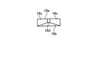
- FIG. 2C is a front view showing a schematic configuration of the tool main body shown in FIG. 2A.
- FIG. 3A is a top view illustrating a schematic configuration of a modified tool body.
- FIG. 3B is a side view showing a schematic configuration of the tool main body shown in FIG. 3A.
- FIG. 4 is a front view showing a schematic configuration of a modified tool body.
- FIG. 5 is a cross-sectional view showing a schematic configuration of an example of a turbine stationary blade.
- FIG. 6A is a perspective view showing a schematic configuration of cooling holes of the turbine stationary blade shown in FIG. 6B is a front view showing a schematic configuration of the cooling hole shown in FIG. 6A.
- 6C is a cross-sectional view showing a schematic configuration of the cooling hole shown in FIG. 6A.
- FIG. 7 is an explanatory diagram for explaining an example of a turbine blade machining method.
- FIG. 8 is an explanatory diagram for explaining another example of a method for processing a turbine blade.
- FIG. 1 is a perspective view showing a schematic configuration of a processing tool according to the present embodiment.
- FIG. 2A is a top view showing a schematic configuration of the tool body.
- 2B is a side view showing a schematic configuration of the tool main body shown in FIG. 2A.
- FIG. 2C is a front view showing a schematic configuration of the tool main body shown in FIG. 2A.
- the processing tool 10 includes a tool body 12 and a vibration unit 13.
- the tool body 12 has a support portion 14 and a tip portion 16 fixed to one end portion of the support portion 14 as shown in FIGS. 1 and 2A to 2C.
- the support part 14 is a rod-shaped member, and the end part on the side where the tip part 16 is not fixed is attached to the vibration part 13.
- the distal end portion 16 has a shape in which the cross section becomes smaller toward the distal end, that is, from the portion connected to the support portion 14 toward the opposite end portion.
- the tip 16 has a polishing region 18 in a certain range on the tip side.
- the polishing region 18 has diamond particles bonded to the surface thereof. Diamond particles are joined to the tip 16 by electrodeposition or the like.
- the polishing region 18 of the tip portion 16 has a quadrangular pyramid shape.
- tip part 16 of a present Example is the shape by which the front-end
- the polishing region 18 has one surface having the largest area as an upper surface 18a, a surface opposite to the upper surface 18a as a bottom surface 18b, and is sandwiched between the upper surface 18a and the bottom surface 18b and extends in the extending direction of the support portion 14.
- the existing surface is a side surface 18c
- the tip surface is a tip 18d.
- the polishing region 18 of the present embodiment has a trapezoidal shape in which the upper surface 18a and the bottom surface 18b become narrower toward the tip 18d.
- the top surface 18a and the bottom surface 18b are isotropic trapezoids, and the angle formed by the hypotenuse is ⁇ 1.
- the upper surface 18 a is a surface parallel to the extending direction of the support portion 14, and the bottom surface 18 b is a surface inclined at a predetermined angle with respect to the extending direction of the support portion 14.
- interval becomes wide as the upper surface 18a and the bottom face 18b leave
- the upper surface 18a and the bottom surface 18b are flat surfaces (planes) in which the cross section perpendicular to the extending direction of the support portion 14 is a straight line.
- the vibration unit 13 is a device that vibrates the tool body 12 in the extending direction (the direction of arrow A).
- the extending direction is a direction in which the support part 14 extends, and is connected to the support part 14 and the tip of the tip part 16 (the narrowed part opposite to the end part connected to the support part 14). It is the direction which tied the edge part.
- various drive sources can be used. For example, an electric polishing machine (a machine that reciprocates a machining tool with electric power) or an excitation source of an ultrasonic polishing machine can be used.
- the processing tool 10 is configured as described above, and the polishing region 18 is formed on the distal end side of the distal end portion 16 of the tool body 12, and the polishing region 18 is brought into contact with the object to be polished, and is polished by sliding.
- the object can be polished.
- the polishing region 18 of the present embodiment is a surface that the bottom surface 18b mainly contacts with the object to be polished, that is, a polishing surface.
- the processing tool 10 has a shape in which the width increases, that is, a tapered shape as the polishing surface 18 of the polishing region 18 is separated from the tip 18d, and a surface (a flat surface in this embodiment). As a result, the tip 18d becomes narrow, and a processing target having a flat surface shape can be processed appropriately. Moreover, since the processing tool 10 can be suitably processed using the polished surface, the tool life can be extended.
- the machining tool 10 can vibrate the polishing region 18 in the extending direction by vibrating the tool body 12 in the extending direction by the vibration unit 13.
- the processing tool 10 vibrates the polishing region 18 with respect to the object to be polished by vibrating the polishing region 18 in the extending direction by the vibration unit 13 while bringing the polishing region 18 into contact with the object to be polished. be able to. Thereby, polishing can be performed efficiently. Further, when the polishing area 13 is vibrated in the extending direction by the vibration unit 13, the polishing area 18 comes into contact with the side wall or the like of the object to be polished when the object to be polished becomes thinner toward the tip. This can be suppressed.
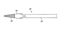
- FIG. 3A is a top view illustrating a schematic configuration of a modified tool body.
- FIG. 3B is a side view showing a schematic configuration of the tool main body shown in FIG. 3A.
- the tool body 22 shown in FIGS. 3A and 3B has a support portion 24 and a tip portion 26.
- a polishing region 28 is provided at the distal end portion 26.
- the polishing region 28 shown in FIGS. 3A and 3B has a trapezoidal shape whose width becomes narrower as the upper surface 28a and the bottom surface 28b (polishing surface) move toward the tip.
- the top surface 28a and the bottom surface 28b are isotropic trapezoids, and the angle formed by the hypotenuse is ⁇ 2.
- ⁇ 2 is an angle smaller than ⁇ 1.
- the processing tool 10 can set the angle of the tapered shape of the polishing surface to various angles. For example, when ⁇ 1 is set to 30 ° and ⁇ 2 is set to 15 °, the processing target can be suitably processed using any of the tool bodies 12 and 22.
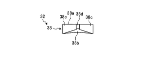
- FIG. 4 is a front view showing a schematic configuration of a modified tool body.
- the polishing area 38 of the tool main body 32 shown in FIG. 4 has a top surface 38a, a side surface 38c, and a tip portion 38d that are flat surfaces.
- the bottom surface 38b of the polishing region 38 has a curved surface in which a cross section orthogonal to the extending direction (a cross section orthogonal to the direction connecting the end portion supported by the support portion and the tip portion) protrudes inward.
- the tool body 32 may have a bottom surface 38b, that is, a polished surface having a curved shape.
- the process target in which the curved surface which protruded outside was formed can be grind
- the tip end portion 16 has a quadrangular pyramid shape and one surface of the quadrangular pyramid has a curved surface.
- the present invention is not limited to this.
- the tip 16 (polishing region) 18 may be a polygonal pyramid, such as a triangular pyramid or a hexagonal pyramid, to form a polished surface.
- the influence which it has on the side wall of a process target can be decreased by setting it as a quadrangular pyramid.
- the machining tool 10 of the present embodiment can perform suitable machining as described above by vibrating the tool body 12 in the extending direction using the vibration unit 13, but is not limited thereto.
- the processing tool 10 may vibrate the tool body 12 in a direction orthogonal to the extending direction or may rotate the tool body 12. Moreover, you may combine the vibration to a various direction.
- the processing tool 10 may not include a drive source that vibrates the tool body 12. Specifically, the polishing region 18 may be manually slid with respect to the processing target.
- the processing tool 10 can suitably process a through hole of a turbine blade, for example, a film cooling hole. More specifically, the processing tool 10 formed a protective film, for example, TBC (Thermal Barrier Coating, high-performance thermal barrier coating for gas turbine) on the surface of the turbine blade base during the production of the turbine blade having the through hole. Thereafter, the protective film can be suitably used for removing a protective film formed on a portion overlapping the through hole or a protective film formed inside the through hole.
- TBC Thermal Barrier Coating, high-performance thermal barrier coating for gas turbine
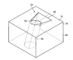
- FIG. 5 is a cross-sectional view showing a schematic configuration of an example of a turbine stationary blade.
- 6A is a perspective view showing a schematic configuration of cooling holes of the turbine stationary blade shown in FIG. 6B is a front view showing a schematic configuration of the cooling hole shown in FIG. 6A.
- 6C is a cross-sectional view showing a schematic configuration of the cooling hole shown in FIG. 6A.
- the cooling holes provided in the turbine stationary blade will be described, but the same applies to the turbine rotor blade. That is, the turbine blade includes both a turbine stationary blade and a turbine blade.
- the turbine stationary blade 43 has a blade body (blade structure portion) 44. Further, the blade body 44 has an outer shroud (end wall structure) fixed to one end (outer in the radial direction) in the longitudinal direction (radial direction of the rotor), and an inner shroud (end) in the other end (inward in the radial direction). Wall structure) is fixed.
- the blade body 44 has a hollow shape, the upstream side in the flow direction of the combustion gas (left side in FIG. 5) has a curved cross-sectional shape, and the downstream side in the flow direction of the combustion gas (right side in FIG. 5). It has a tapered cross-sectional shape.
- the wing body 44 is partitioned into three spaces by two partition walls 51.
- the blade body 44 is formed with a plurality of cooling holes 52 penetrating inside and outside at predetermined positions.
- the wing body 44 has partition plates 55a, 55b, and 55c fixed to the inside thereof.
- the partition plates 55a, 55b, and 55c have a cylindrical shape, and end portions on the side of each shroud are expanded to be fixed to the shrouds.
- the partition plates 55a, 55b, and 55c are fixed on the inner side, so that the cavity 62 is defined.
- the partition plates 55a, 55b, and 55c have a large number of through holes 59 formed at almost equal intervals over the entire region.
- the cooling air (cooling medium) from the cooling passage is supplied to the turbine stationary blade 43
- the cooling air is first introduced into the blade body 44, that is, inside the partition plate 55.
- the cooling air in the partition plate 55 is then injected into the cavity 58 through a large number of through holes 59 formed in the partition plate 55, where the inner wall surface of the blade body 44 is impingement cooled.
- the cooling air in the cavity 58 is discharged to the outside (combustion gas passage) through the numerous cooling holes 52 and flows along the outer wall surfaces of the blade body 44, the back profile 45, and the ventral profile 46.
- Film cooling of the wall surface film cooling.
- the cooling hole 52 is formed in the blade body 44 as described above.
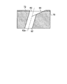
- the wing body 44 has a protective film 72 formed on the surface of the base 70.
- the protective film 72 is provided in a region on the surface of the blade body 44 where the cooling holes 52 are not formed.
- the protective film 72 is a film having a function of protecting the surface of the base body 70, and is formed of TBC, for example. Since the blade main body 44 is provided with the protective film 72, the durability of the surface can be improved, and the durability of the turbine vane can be increased.
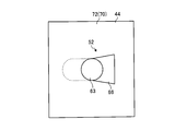
- the cooling hole 52 has a cylindrical portion 62 that is inclined with respect to the surface (the surface on which the protective film is formed) from the inside of the blade body 44, and the end portion on the surface side of the cylindrical portion 62 becomes the opening 63. .
- the cylindrical portion 62 is inclined with respect to the direction in which the central axis 62a is orthogonal to the surface.
- the cooling hole 52 extends from the opening 63 at the downstream side of the cooling air flowing from the inside of the blade main body 44 to the surface, that is, at the end inclined to the perpendicular of the inclined cylindrical portion 62. 66 is formed.
- the extended portion 66 is formed with a surface where the angle formed with the direction orthogonal to the surface is larger than that of the cylindrical portion 62, that is, the inclination is gentle.
- the extended portion 66 has a flat surface. Further, the extended portion 66 has a shape in which the width increases as the opening portion moves away from the opening 63 as shown in FIG. 6B.
- the turbine vane 43 has a shape in which the cooling hole 52 is formed by connecting the cylindrical portion 62 and the expansion portion 66, thereby allowing cooling air discharged from the inside of the blade body 44 to flow to the surface along the surface of the blade body 44. It can be made easier.
- FIG. 7 is an explanatory diagram for explaining an example of a turbine blade machining method.
- a base body 102 having a through hole 103 to be a cooling hole is formed, and as shown in step S14, a protective film 104 is formed on the surface of the base body 102.
- the protective film 104 can be formed on the surface of the substrate 102 by thermal spraying, for example.
- the protective film 104 is uniformly formed on the surface of the base 102, and thus the protective film 104 is also formed in a region overlapping with the through hole 103.
- the processing method inserts the tip 16 of the processing tool 10 into the region where the through hole 103 is formed (insertion step).
- the distal end portion 16 is inserted in such a direction that the bottom surface 18b (polishing surface) of the polishing region 18 of the distal end portion 16 faces the through hole 103 (the protective film 104 overlapping the through hole 103).
- the distal end portion 16 is vibrated by the vibrating portion 13. At this time, it may be vibrated before insertion or after insertion.
- step S18 the tip portion 16 is vibrated by the vibration portion 13 while the polishing region 18 of the tip portion 16 is in contact with the protective film 104 that overlaps the through hole 103.
- the overlapping protective film 104 is polished and removed (removal step).
- the processing method uses the processing tool 10 to remove the protective film 104 that overlaps the through-hole 103, and as shown in step S ⁇ b> 20, the protective film is located at a position that does not overlap the opening 63 and the extended part 66 of the cylindrical part 62.
- a turbine vane in which 72 is formed can be created.
- the cooling film 52 is efficiently covered with the protective film 72 by removing the protective film 104 that overlaps the through hole 103 by polishing using the processing tool 10. There can be no state.
- the through hole 103 and the polishing surface can be made substantially parallel, and the polishing surface penetrates during processing.
- the contact with the hole 103 and the cutting of the through hole 103 can be suppressed.
- the range of the through holes 103 that can be processed simultaneously can be increased, the time required for removing the protective film 104 can be shortened.
- the polishing surface can be moved along the inclination direction (tapered shape) of the through-hole 103. Thereby, it can suppress that a grinding
- the processing tool 10 having the above-described shape, specifically, the polishing surface has a surface shape.
- a tapered processing tool it is preferable to use a tapered processing tool, but the present invention is not limited to this.
- the shape of the tool for polishing the protective film can be various.
- a tool body having a cylindrical and conical tip portion may be used, or a tool body having a flat plate tip portion may be used.
- step S12 the base 102 in which the through hole 103 serving as a cooling hole is formed is formed, and as shown in step S14, the protective film 104 is formed on the surface of the base 102. .
- step S ⁇ b> 32 the tip end portion 92 of the processing tool 90 is inserted into the region where the through hole 103 is formed, and the polishing region of the tip end portion 92 overlaps the through hole 103.
- the tip portion 92 is vibrated by the vibrating portion while being in contact with the protective film 104, thereby polishing the protective film 104 overlapping the through-hole 103 and removing a part thereof (pretreatment step).
- tip part 92 becomes a cylindrical shape.
- the processing tool 90 may rotate the distal end portion 92 with a rotating device such as a portable grinder without vibrating.
- step S18 in the processing method, the tip end portion 16 is inserted so that the bottom surface 18b of the polishing region 18 of the tip end portion 16 of the processing tool 10 faces the through hole 103, and the polishing region 18 is passed through the through hole.
- the top end portion 16 is vibrated by the vibrating portion 13 while being in contact with the protective film 104 that overlaps the 103, that is, the bottom surface 18b of the polishing region 18 is reciprocated along the insertion direction, thereby overlapping the through hole 103.
- 104 is polished and removed (insertion step, removal step).
- the tip portion 92a of the processing tool 90 is inserted into the region where the through hole 103 is formed, more specifically, the region where the cylindrical portion is formed. While the polishing region is in contact with the protective film 104 that overlaps the through-hole 103, the tip portion 92 is vibrated by the vibrating portion, whereby the protective film 104 that overlaps the through-hole 103 is polished and removed (post-processing step).
- the tip portion 92a has a columnar shape in which the polishing region has a smaller diameter than the cylindrical portion.
- the front end portion 92a is inserted into the cylindrical portion, and the protective film 104 overlapping the through hole 103 is polished and removed, so that the protective film 104 attached to the inside of the cylindrical portion can be more reliably removed. it can.
- the processing method uses the processing tools 10 and 90 to remove the protective film 104 that overlaps the through-hole 103, so that the opening 63 and the expansion portion 66 of the cylindrical portion 62 are formed as shown in Step S ⁇ b> 20.
- a turbine vane having a protective film 72 formed at a position where it does not overlap can be created.
- the processing method shown in FIG. 8 uses a processing tool 90 to remove the protective film 104 that overlaps the through-hole 103 (rough processing), and uses the processing tool 10 to correspond to an extended portion whose surface is flat.
- the protective film 104 that overlaps with the cylindrical portion is removed, and the protective film 104 attached to the cylindrical portion can be removed using the processing tool 90.
- the protective film 104 can be efficiently removed from the cooling hole with high accuracy.
- a tool suitable for processing each part can be used. Thereby, it is possible to perform processing while suppressing polishing of the through-hole 103.
- the turbine blade manufactured by processing with the above-described processing tool and the turbine blade manufactured by processing with the above-described processing method have through holes such as cooling holes with higher accuracy,
- the performance can be made higher.
- the performance of the turbine blade can be increased.
- the turbine blade is removed from the protective film 104 such as a sprayed film while suppressing adverse effects on the inside of the through hole 103.
- the protective film 104 can be appropriately formed to increase durability, and the protective film 104 is removed with high accuracy while maintaining the shape of the through hole 103, so that the through hole 103 is cooled.
- the cooling performance when used as a hole can be increased.
Landscapes
- Engineering & Computer Science (AREA)
- Mechanical Engineering (AREA)
- General Engineering & Computer Science (AREA)
- Chemical & Material Sciences (AREA)
- Materials Engineering (AREA)
- Physics & Mathematics (AREA)
- Plasma & Fusion (AREA)
- Chemical Kinetics & Catalysis (AREA)
- Metallurgy (AREA)
- Organic Chemistry (AREA)
- Turbine Rotor Nozzle Sealing (AREA)
- Grinding And Polishing Of Tertiary Curved Surfaces And Surfaces With Complex Shapes (AREA)
Abstract
Description
12、22 工具本体
13 加振部
14、24 支持部
16、26 先端部
18、28 研磨領域
18a 上面
18b 底面(研磨面)
18c 側面
18d 先端
43 タービン静翼(タービン翼)
44 翼本体
52 冷却孔(貫通孔)
70 基体
72 保護膜
102 基体
103 貫通孔
104 保護膜
Claims (15)
- 基体の表面に保護膜が形成されたタービン翼の貫通孔を加工するタービン翼の加工方法であって、
先端に研磨領域が設けられた加工工具を、前記研磨領域が前記貫通孔の表面と対面する向きで前記貫通孔に挿入する挿入工程と、
前記貫通孔に挿入した加工工具の前記研磨領域で、前記貫通孔に積層された保護膜を研磨して、前記貫通孔に積層された保護膜を除去する除去工程と、を有することを特徴とするタービン翼の加工方法。 - 前記加工工具は、前記研磨領域が、前記基体の表面から見た前記貫通孔の形状に沿った形状であることを特徴とする請求項1に記載のタービン翼の加工方法。
- 前記加工工具は、前記研磨領域が、先端に向かうにしたがって、細くなる角錐形状の少なくとも1面に形成されていることを特徴とする請求項2に記載のタービン翼の加工方法。
- 前記除去工程は、加振部により前記加工工具を振動させることにより、前記研磨領域で前記保護膜を研磨することを特徴とする請求項1から3のいずれか一項に記載のタービン翼の加工方法。
- 前記加振部は、前記研磨領域を、前記貫通孔への挿入方向に沿って往復移動させることを特徴とする請求項4に記載のタービン翼の加工方法。
- 前記挿入工程の前に、先端に研磨領域が設けられた棒状加工工具を、前記研磨領域が前記貫通孔の表面と対面する向きで前記貫通孔に挿入し、前記貫通孔に挿入した加工工具の前記研磨領域を回転させつつ前記保護膜に接触させて前記保護膜を研磨して、前記貫通孔に積層された保護膜の一部を除去する前処理工程をさらに有することを特徴とする請求項1から5のいずれか一項に記載のタービン翼の加工方法。
- 前記除去工程の後に、先端に研磨領域が設けられた棒状加工工具を、前記研磨領域が前記貫通孔の表面と対面する向きで前記貫通孔に挿入し、前記貫通孔に挿入した加工工具の前記研磨領域で、前記貫通孔に積層された保護膜を研磨して、前記貫通孔に積層された保護膜を除去する後処理工程をさらに有することを特徴とする請求項1から6のいずれか一項に記載のタービン翼の加工方法。
- 前記保護膜は、前記基体の表面に溶射で形成されていることを特徴とする請求項1から7のいずれか一項に記載のタービン翼の加工方法。
- 前記加工工具は、前記研磨領域にダイヤモンドの粒子が接合されていることを特徴とする請求項1から8のいずれか一項に記載のタービン翼の加工方法。
- ダイヤモンドの粒子が接合された研磨領域が形成された研磨面を少なくとも1面備える先端部と、
前記先端部の一方の端部に連結された支持部と、を有し、
前記研磨面は、前記支持部で支持されている端部とは反対側の端部である先端に向かうにしたがって、幅が狭くなる面であることを特徴とする加工工具。 - 前記研磨面は、前記支持部で支持されている端部と前記先端とを結ぶ方向に直交する断面が直線となることを特徴とする請求項10に記載の加工工具。
- 前記研磨面は、前記支持部で支持されている端部と前記先端とを結ぶ方向に直交する断面が内側に凸となる曲線となることを特徴とする請求項10に記載の加工工具。
- 前記支持部に連結され、前記支持部を介して、前記先端部を、前記支持部で支持されている端部と前記先端とを結ぶ方向に往復運動させる加振部をさらに有することを特徴とする請求項10から12のいずれか一項に記載の加工工具。
- 請求項1から9のいずれか一項に記載のタービン翼の加工方法で貫通孔が加工されたことを特徴とするタービン翼。
- 請求項10から13のいずれか一項に記載の加工工具で貫通孔が加工されたことを特徴とするタービン翼。
Priority Applications (5)
| Application Number | Priority Date | Filing Date | Title |
|---|---|---|---|
| EP14756808.3A EP2952709B1 (en) | 2013-02-26 | 2014-02-12 | Turbine blade machining method |
| CN201480005848.1A CN104968916B (zh) | 2013-02-26 | 2014-02-12 | 涡轮叶片的加工方法、加工工具以及涡轮叶片 |
| KR1020157019965A KR101811112B1 (ko) | 2013-02-26 | 2014-02-12 | 터빈 날개 가공 방법, 가공 공구 및 터빈 날개 |
| US14/762,062 US9903208B2 (en) | 2013-02-26 | 2014-02-12 | Turbine blade machining method, machining tool, and turbine blade |
| US15/869,696 US20180156040A1 (en) | 2013-02-26 | 2018-01-12 | Turbine blade machining method, machining tool, and turbine blade |
Applications Claiming Priority (2)
| Application Number | Priority Date | Filing Date | Title |
|---|---|---|---|
| JP2013-036458 | 2013-02-26 | ||
| JP2013036458A JP5456192B1 (ja) | 2013-02-26 | 2013-02-26 | タービン翼の加工方法、加工工具及びタービン翼 |
Related Child Applications (2)
| Application Number | Title | Priority Date | Filing Date |
|---|---|---|---|
| US14/762,062 A-371-Of-International US9903208B2 (en) | 2013-02-26 | 2014-02-12 | Turbine blade machining method, machining tool, and turbine blade |
| US15/869,696 Division US20180156040A1 (en) | 2013-02-26 | 2018-01-12 | Turbine blade machining method, machining tool, and turbine blade |
Publications (1)
| Publication Number | Publication Date |
|---|---|
| WO2014132797A1 true WO2014132797A1 (ja) | 2014-09-04 |
Family
ID=50614603
Family Applications (1)
| Application Number | Title | Priority Date | Filing Date |
|---|---|---|---|
| PCT/JP2014/053196 WO2014132797A1 (ja) | 2013-02-26 | 2014-02-12 | タービン翼の加工方法、加工工具及びタービン翼 |
Country Status (6)
| Country | Link |
|---|---|
| US (2) | US9903208B2 (ja) |
| EP (1) | EP2952709B1 (ja) |
| JP (1) | JP5456192B1 (ja) |
| KR (1) | KR101811112B1 (ja) |
| CN (1) | CN104968916B (ja) |
| WO (1) | WO2014132797A1 (ja) |
Families Citing this family (9)
| Publication number | Priority date | Publication date | Assignee | Title |
|---|---|---|---|---|
| BR112013001186A2 (pt) | 2010-07-16 | 2016-05-31 | Michael Arnouse | sistema de computação e comunicação |
| JP2015196228A (ja) * | 2014-04-02 | 2015-11-09 | 三菱日立パワーシステムズ株式会社 | 先端工具、切削機械、部品及び膜体の切削方法 |
| CN107685220B (zh) * | 2016-08-04 | 2019-06-07 | 中国科学院金属研究所 | 一种复杂薄壁高温合金热端部件裂纹的修复方法 |
| CN108115481A (zh) * | 2016-11-29 | 2018-06-05 | 沈阳黎明航空发动机(集团)有限责任公司 | 一种解决气冷涡轮叶片热障涂层堵孔的方法 |
| US11365638B2 (en) | 2017-08-14 | 2022-06-21 | Siemens Energy Global GmbH & Co. KG | Turbine blade and corresponding method of servicing |
| US10774656B2 (en) * | 2018-04-09 | 2020-09-15 | General Electric Company | Turbine airfoil multilayer exterior wall |
| US10995621B2 (en) | 2018-11-06 | 2021-05-04 | General Electric Company | Turbine airfoil with multiple walls and internal thermal barrier coating |
| US11603769B2 (en) | 2021-08-13 | 2023-03-14 | Raytheon Technologies Corporation | Forming lined cooling aperture(s) in a turbine engine component |
| US20230193772A1 (en) * | 2021-12-21 | 2023-06-22 | Raytheon Technologies Corporation | Fabrication of cooling holes using laser machining and ultrasonic machining |
Citations (9)
| Publication number | Priority date | Publication date | Assignee | Title |
|---|---|---|---|---|
| JPS61144947U (ja) * | 1985-03-01 | 1986-09-06 | ||
| JPS63216676A (ja) * | 1987-03-06 | 1988-09-08 | Y K Trading Kk | 加工用粒体 |
| JPH03234451A (ja) * | 1990-02-09 | 1991-10-18 | Res Dev Corp Of Japan | ねじり振動を利用した研摩法 |
| JPH0430956A (ja) * | 1990-05-25 | 1992-02-03 | Nippon Electric Ind Co Ltd | 超音波振動研磨装置 |
| JP2002105666A (ja) * | 2000-09-28 | 2002-04-10 | Mitsubishi Heavy Ind Ltd | 研磨層、燃焼エンジン、ガスタービン、及び、その製造方法 |
| JP2002256808A (ja) * | 2001-02-28 | 2002-09-11 | Mitsubishi Heavy Ind Ltd | 燃焼エンジン、ガスタービン及び研磨層 |
| JP2009510302A (ja) * | 2005-09-26 | 2009-03-12 | シーメンス アクチエンゲゼルシヤフト | 露出した開口部を備えるコーティングされるべきガスタービン構成部品を製造する方法、この方法を実施する装置、およびフィルム冷却開口部を備えるコーティング可能なタービン羽根 |
| JP2012082700A (ja) | 2010-10-07 | 2012-04-26 | Hitachi Ltd | タービン翼の冷却孔加工方法 |
| JP2012140952A (ja) | 2011-01-04 | 2012-07-26 | General Electric Co <Ge> | フィルム冷却製品を提供する方法 |
Family Cites Families (31)
| Publication number | Priority date | Publication date | Assignee | Title |
|---|---|---|---|---|
| US2452211A (en) * | 1944-10-17 | 1948-10-26 | Scophony Corp Of America | Machine for mechanically working materials |
| JPS61144947A (ja) | 1984-12-19 | 1986-07-02 | Hitachi Ltd | 通信制御装置 |
| US4743462A (en) * | 1986-07-14 | 1988-05-10 | United Technologies Corporation | Method for preventing closure of cooling holes in hollow, air cooled turbine engine components during application of a plasma spray coating |
| US5216808A (en) * | 1990-11-13 | 1993-06-08 | General Electric Company | Method for making or repairing a gas turbine engine component |
| US5702288A (en) * | 1995-08-30 | 1997-12-30 | United Technologies Corporation | Method of removing excess overlay coating from within cooling holes of aluminide coated gas turbine engine components |
| US5749770A (en) * | 1996-07-08 | 1998-05-12 | S-B Power Tool Company | Method and apparatus for sanding a plurality of work-pieces having respective surfaces of varying contours |
| JP2810023B2 (ja) | 1996-09-18 | 1998-10-15 | 株式会社東芝 | 高温部材冷却装置 |
| US5902647A (en) * | 1996-12-03 | 1999-05-11 | General Electric Company | Method for protecting passage holes in a metal-based substrate from becoming obstructed, and related compositions |
| US6544346B1 (en) * | 1997-07-01 | 2003-04-08 | General Electric Company | Method for repairing a thermal barrier coating |
| US6042879A (en) * | 1997-07-02 | 2000-03-28 | United Technologies Corporation | Method for preparing an apertured article to be recoated |
| GB9723762D0 (en) * | 1997-11-12 | 1998-01-07 | Rolls Royce Plc | A method of coating a component |
| DE19859763A1 (de) * | 1998-12-23 | 2000-06-29 | Abb Alstom Power Ch Ag | Verfahren zum Unschädlichmachen von beim Beschichten mit einer Schutzschicht entstehenden Verengungen in den Kühllöchern von gasgekühlten Teilen |
| EP1076107B1 (en) * | 1999-08-09 | 2003-10-08 | ALSTOM (Switzerland) Ltd | Process of plugging cooling holes of a gas turbine component |
| US7204019B2 (en) * | 2001-08-23 | 2007-04-17 | United Technologies Corporation | Method for repairing an apertured gas turbine component |
| US6663919B2 (en) * | 2002-03-01 | 2003-12-16 | General Electric Company | Process of removing a coating deposit from a through-hole in a component and component processed thereby |
| EP1365039A1 (en) * | 2002-05-24 | 2003-11-26 | ALSTOM (Switzerland) Ltd | Process of masking colling holes of a gas turbine component |
| DE60310168T2 (de) * | 2002-08-02 | 2007-09-13 | Alstom Technology Ltd. | Verfahren zum Schutz von Teilflächen eines Werkstücks |
| DE10392994C5 (de) * | 2002-08-02 | 2013-08-14 | Mitsubishi Heavy Industries, Ltd. | Wärmesperrschicht-Beschichtungsverfahren und dessen Verwendung |
| US7101263B2 (en) * | 2002-11-06 | 2006-09-05 | United Technologies Corporation | Flank superabrasive machining |
| US7805822B2 (en) * | 2003-12-15 | 2010-10-05 | Turbocombustor Technology, Inc. | Process for removing thermal barrier coatings |
| JP5039837B2 (ja) | 2005-03-30 | 2012-10-03 | 三菱重工業株式会社 | ガスタービン用高温部材 |
| EP1868766A1 (de) * | 2005-04-07 | 2007-12-26 | Alstom Technology Ltd | Verfahren zum reparieren oder erneuern von kühllöchern einer beschichteten komponente einer gasturbine |
| US20060264162A1 (en) * | 2005-05-23 | 2006-11-23 | Roger Yu | Fine abrasive tool and method of making same |
| EP1772594A1 (de) * | 2005-10-04 | 2007-04-11 | Siemens Aktiengesellschaft | Verfahren zum Schützen von Öffnungen eines Bauteils bei einem Bearbeitungsprozess gegen ein Eindringen von Material und Polysiloxan enthaltende keramische Zusammensetzung |
| GB0610578D0 (en) * | 2006-05-27 | 2006-07-05 | Rolls Royce Plc | Method of removing deposits |
| US20090142548A1 (en) * | 2007-10-18 | 2009-06-04 | David Bruce Patterson | Air cooled gas turbine components and methods of manufacturing and repairing the same |
| FR2949204B1 (fr) * | 2009-08-21 | 2011-10-14 | Snecma | Machine d'usinage pour cmc par fraisage et abrasion par ultrasons |
| US9696035B2 (en) * | 2010-10-29 | 2017-07-04 | General Electric Company | Method of forming a cooling hole by laser drilling |
| US20120167389A1 (en) * | 2011-01-04 | 2012-07-05 | General Electric Company | Method for providing a film cooled article |
| US9598979B2 (en) * | 2012-02-15 | 2017-03-21 | United Technologies Corporation | Manufacturing methods for multi-lobed cooling holes |
| US9523287B2 (en) * | 2013-01-18 | 2016-12-20 | General Electric Company | Cooling hole cleaning method and apparatus |
-
2013
- 2013-02-26 JP JP2013036458A patent/JP5456192B1/ja active Active
-
2014
- 2014-02-12 KR KR1020157019965A patent/KR101811112B1/ko active IP Right Grant
- 2014-02-12 EP EP14756808.3A patent/EP2952709B1/en active Active
- 2014-02-12 CN CN201480005848.1A patent/CN104968916B/zh active Active
- 2014-02-12 WO PCT/JP2014/053196 patent/WO2014132797A1/ja active Application Filing
- 2014-02-12 US US14/762,062 patent/US9903208B2/en active Active
-
2018
- 2018-01-12 US US15/869,696 patent/US20180156040A1/en not_active Abandoned
Patent Citations (9)
| Publication number | Priority date | Publication date | Assignee | Title |
|---|---|---|---|---|
| JPS61144947U (ja) * | 1985-03-01 | 1986-09-06 | ||
| JPS63216676A (ja) * | 1987-03-06 | 1988-09-08 | Y K Trading Kk | 加工用粒体 |
| JPH03234451A (ja) * | 1990-02-09 | 1991-10-18 | Res Dev Corp Of Japan | ねじり振動を利用した研摩法 |
| JPH0430956A (ja) * | 1990-05-25 | 1992-02-03 | Nippon Electric Ind Co Ltd | 超音波振動研磨装置 |
| JP2002105666A (ja) * | 2000-09-28 | 2002-04-10 | Mitsubishi Heavy Ind Ltd | 研磨層、燃焼エンジン、ガスタービン、及び、その製造方法 |
| JP2002256808A (ja) * | 2001-02-28 | 2002-09-11 | Mitsubishi Heavy Ind Ltd | 燃焼エンジン、ガスタービン及び研磨層 |
| JP2009510302A (ja) * | 2005-09-26 | 2009-03-12 | シーメンス アクチエンゲゼルシヤフト | 露出した開口部を備えるコーティングされるべきガスタービン構成部品を製造する方法、この方法を実施する装置、およびフィルム冷却開口部を備えるコーティング可能なタービン羽根 |
| JP2012082700A (ja) | 2010-10-07 | 2012-04-26 | Hitachi Ltd | タービン翼の冷却孔加工方法 |
| JP2012140952A (ja) | 2011-01-04 | 2012-07-26 | General Electric Co <Ge> | フィルム冷却製品を提供する方法 |
Also Published As
| Publication number | Publication date |
|---|---|
| US20180156040A1 (en) | 2018-06-07 |
| JP5456192B1 (ja) | 2014-03-26 |
| US20150354371A1 (en) | 2015-12-10 |
| EP2952709A4 (en) | 2016-03-02 |
| JP2014163330A (ja) | 2014-09-08 |
| CN104968916A (zh) | 2015-10-07 |
| EP2952709A1 (en) | 2015-12-09 |
| CN104968916B (zh) | 2016-11-16 |
| KR101811112B1 (ko) | 2017-12-20 |
| US9903208B2 (en) | 2018-02-27 |
| KR20150100854A (ko) | 2015-09-02 |
| EP2952709B1 (en) | 2019-08-28 |
Similar Documents
| Publication | Publication Date | Title |
|---|---|---|
| JP5456192B1 (ja) | タービン翼の加工方法、加工工具及びタービン翼 | |
| JP6405357B2 (ja) | 複雑なフィルム穴を形成するための付加形成方法 | |
| US8286348B2 (en) | Method of manufacturing and refinishing integrally bladed rotors | |
| US9676046B2 (en) | Electrical discharge machining method | |
| US9511469B2 (en) | Polishing assembly and method for polishing using a platform and barrier in a tumbling process | |
| US8105133B2 (en) | Airfoil mask, airfoil and mask system | |
| Cao et al. | Study on the material removal process in ultrasonic-assisted grinding of SiC ceramics using smooth particle hydrodynamic (SPH) method | |
| RU2005112562A (ru) | Способы и системы микрообработки | |
| US20170361422A1 (en) | Polishing method for turbine components | |
| US20210060709A1 (en) | Laser rough drill and full edm finish for shaped cooling holes | |
| JP2009255288A (ja) | ブリスクブレードの前縁を空力的に形成する方法 | |
| TW201448006A (zh) | 晶圓的切削方法 | |
| JP5846742B2 (ja) | ダイ本体からハニカム押出ダイを作製する方法 | |
| US20090113683A1 (en) | Method and apparatus for machining the blade tips of rotor wheel drums of turbomachines | |
| EP2099583A1 (en) | Method and device for pin removal in a confined space | |
| JP2015533973A (ja) | レーザピーニングされる部品の後処理 | |
| US20160169013A1 (en) | Gas Turbine Engine Component with Abrasive Surface Formed by Electrical Discharge Machining | |
| JP6555145B2 (ja) | 切削工具、切削工具を有する加工装置および切削工具を用いた加工方法 | |
| JP2014094433A (ja) | 遠心回転機のインペラの製造方法 | |
| US20140323022A1 (en) | Airfoil edge form transfer grinding tool | |
| US11141800B2 (en) | Device and method for re-contouring a gas turbine blade | |
| JP6469443B2 (ja) | フライス加工および表面加工の方法およびデバイス | |
| JP7150392B2 (ja) | スリットノズルの製造方法及びスリットノズル | |
| JP6507925B2 (ja) | ガラスの切断方法 | |
| JP2019119020A (ja) | 切断用ブレード |
Legal Events
| Date | Code | Title | Description |
|---|---|---|---|
| 121 | Ep: the epo has been informed by wipo that ep was designated in this application |
Ref document number: 14756808 Country of ref document: EP Kind code of ref document: A1 |
|
| WWE | Wipo information: entry into national phase |
Ref document number: 14762062 Country of ref document: US |
|
| ENP | Entry into the national phase |
Ref document number: 20157019965 Country of ref document: KR Kind code of ref document: A |
|
| WWE | Wipo information: entry into national phase |
Ref document number: 2014756808 Country of ref document: EP |
|
| NENP | Non-entry into the national phase |
Ref country code: DE |