WO2014129094A1 - 電線圧着装置、及び電線圧着方法 - Google Patents
電線圧着装置、及び電線圧着方法 Download PDFInfo
- Publication number
- WO2014129094A1 WO2014129094A1 PCT/JP2013/085282 JP2013085282W WO2014129094A1 WO 2014129094 A1 WO2014129094 A1 WO 2014129094A1 JP 2013085282 W JP2013085282 W JP 2013085282W WO 2014129094 A1 WO2014129094 A1 WO 2014129094A1
- Authority
- WO
- WIPO (PCT)
- Prior art keywords
- crimping
- wire
- guide
- electric wire
- tip
- Prior art date
- Legal status (The legal status is an assumption and is not a legal conclusion. Google has not performed a legal analysis and makes no representation as to the accuracy of the status listed.)
- Ceased
Links
Images








Classifications
-
- H—ELECTRICITY
- H01—ELECTRIC ELEMENTS
- H01R—ELECTRICALLY-CONDUCTIVE CONNECTIONS; STRUCTURAL ASSOCIATIONS OF A PLURALITY OF MUTUALLY-INSULATED ELECTRICAL CONNECTING ELEMENTS; COUPLING DEVICES; CURRENT COLLECTORS
- H01R43/00—Apparatus or processes specially adapted for manufacturing, assembling, maintaining, or repairing of line connectors or current collectors or for joining electric conductors
- H01R43/04—Apparatus or processes specially adapted for manufacturing, assembling, maintaining, or repairing of line connectors or current collectors or for joining electric conductors for forming connections by deformation, e.g. crimping tool
- H01R43/048—Crimping apparatus or processes
-
- H—ELECTRICITY
- H01—ELECTRIC ELEMENTS
- H01R—ELECTRICALLY-CONDUCTIVE CONNECTIONS; STRUCTURAL ASSOCIATIONS OF A PLURALITY OF MUTUALLY-INSULATED ELECTRICAL CONNECTING ELEMENTS; COUPLING DEVICES; CURRENT COLLECTORS
- H01R43/00—Apparatus or processes specially adapted for manufacturing, assembling, maintaining, or repairing of line connectors or current collectors or for joining electric conductors
- H01R43/04—Apparatus or processes specially adapted for manufacturing, assembling, maintaining, or repairing of line connectors or current collectors or for joining electric conductors for forming connections by deformation, e.g. crimping tool
- H01R43/048—Crimping apparatus or processes
- H01R43/052—Crimping apparatus or processes with wire-feeding mechanism
-
- H—ELECTRICITY
- H01—ELECTRIC ELEMENTS
- H01R—ELECTRICALLY-CONDUCTIVE CONNECTIONS; STRUCTURAL ASSOCIATIONS OF A PLURALITY OF MUTUALLY-INSULATED ELECTRICAL CONNECTING ELEMENTS; COUPLING DEVICES; CURRENT COLLECTORS
- H01R4/00—Electrically-conductive connections between two or more conductive members in direct contact, i.e. touching one another; Means for effecting or maintaining such contact; Electrically-conductive connections having two or more spaced connecting locations for conductors and using contact members penetrating insulation
- H01R4/10—Electrically-conductive connections between two or more conductive members in direct contact, i.e. touching one another; Means for effecting or maintaining such contact; Electrically-conductive connections having two or more spaced connecting locations for conductors and using contact members penetrating insulation effected solely by twisting, wrapping, bending, crimping, or other permanent deformation
- H01R4/18—Electrically-conductive connections between two or more conductive members in direct contact, i.e. touching one another; Means for effecting or maintaining such contact; Electrically-conductive connections having two or more spaced connecting locations for conductors and using contact members penetrating insulation effected solely by twisting, wrapping, bending, crimping, or other permanent deformation by crimping
- H01R4/20—Electrically-conductive connections between two or more conductive members in direct contact, i.e. touching one another; Means for effecting or maintaining such contact; Electrically-conductive connections having two or more spaced connecting locations for conductors and using contact members penetrating insulation effected solely by twisting, wrapping, bending, crimping, or other permanent deformation by crimping using a crimping sleeve
-
- H—ELECTRICITY
- H01—ELECTRIC ELEMENTS
- H01R—ELECTRICALLY-CONDUCTIVE CONNECTIONS; STRUCTURAL ASSOCIATIONS OF A PLURALITY OF MUTUALLY-INSULATED ELECTRICAL CONNECTING ELEMENTS; COUPLING DEVICES; CURRENT COLLECTORS
- H01R13/00—Details of coupling devices of the kinds covered by groups H01R12/70 or H01R24/00 - H01R33/00
- H01R13/02—Contact members
- H01R13/10—Sockets for co-operation with pins or blades
- H01R13/11—Resilient sockets
- H01R13/113—Resilient sockets co-operating with pins or blades having a rectangular transverse section
-
- H—ELECTRICITY
- H01—ELECTRIC ELEMENTS
- H01R—ELECTRICALLY-CONDUCTIVE CONNECTIONS; STRUCTURAL ASSOCIATIONS OF A PLURALITY OF MUTUALLY-INSULATED ELECTRICAL CONNECTING ELEMENTS; COUPLING DEVICES; CURRENT COLLECTORS
- H01R4/00—Electrically-conductive connections between two or more conductive members in direct contact, i.e. touching one another; Means for effecting or maintaining such contact; Electrically-conductive connections having two or more spaced connecting locations for conductors and using contact members penetrating insulation
- H01R4/58—Electrically-conductive connections between two or more conductive members in direct contact, i.e. touching one another; Means for effecting or maintaining such contact; Electrically-conductive connections having two or more spaced connecting locations for conductors and using contact members penetrating insulation characterised by the form or material of the contacting members
- H01R4/62—Connections between conductors of different materials; Connections between or with aluminium or steel-core aluminium conductors
-
- H—ELECTRICITY
- H01—ELECTRIC ELEMENTS
- H01R—ELECTRICALLY-CONDUCTIVE CONNECTIONS; STRUCTURAL ASSOCIATIONS OF A PLURALITY OF MUTUALLY-INSULATED ELECTRICAL CONNECTING ELEMENTS; COUPLING DEVICES; CURRENT COLLECTORS
- H01R43/00—Apparatus or processes specially adapted for manufacturing, assembling, maintaining, or repairing of line connectors or current collectors or for joining electric conductors
- H01R43/04—Apparatus or processes specially adapted for manufacturing, assembling, maintaining, or repairing of line connectors or current collectors or for joining electric conductors for forming connections by deformation, e.g. crimping tool
- H01R43/048—Crimping apparatus or processes
- H01R43/05—Crimping apparatus or processes with wire-insulation stripping
-
- H—ELECTRICITY
- H01—ELECTRIC ELEMENTS
- H01R—ELECTRICALLY-CONDUCTIVE CONNECTIONS; STRUCTURAL ASSOCIATIONS OF A PLURALITY OF MUTUALLY-INSULATED ELECTRICAL CONNECTING ELEMENTS; COUPLING DEVICES; CURRENT COLLECTORS
- H01R43/00—Apparatus or processes specially adapted for manufacturing, assembling, maintaining, or repairing of line connectors or current collectors or for joining electric conductors
- H01R43/04—Apparatus or processes specially adapted for manufacturing, assembling, maintaining, or repairing of line connectors or current collectors or for joining electric conductors for forming connections by deformation, e.g. crimping tool
- H01R43/048—Crimping apparatus or processes
- H01R43/055—Crimping apparatus or processes with contact member feeding mechanism
-
- Y—GENERAL TAGGING OF NEW TECHNOLOGICAL DEVELOPMENTS; GENERAL TAGGING OF CROSS-SECTIONAL TECHNOLOGIES SPANNING OVER SEVERAL SECTIONS OF THE IPC; TECHNICAL SUBJECTS COVERED BY FORMER USPC CROSS-REFERENCE ART COLLECTIONS [XRACs] AND DIGESTS
- Y10—TECHNICAL SUBJECTS COVERED BY FORMER USPC
- Y10T—TECHNICAL SUBJECTS COVERED BY FORMER US CLASSIFICATION
- Y10T29/00—Metal working
- Y10T29/49—Method of mechanical manufacture
- Y10T29/49002—Electrical device making
- Y10T29/49117—Conductor or circuit manufacturing
- Y10T29/49174—Assembling terminal to elongated conductor
- Y10T29/49181—Assembling terminal to elongated conductor by deforming
- Y10T29/49185—Assembling terminal to elongated conductor by deforming of terminal
-
- Y—GENERAL TAGGING OF NEW TECHNOLOGICAL DEVELOPMENTS; GENERAL TAGGING OF CROSS-SECTIONAL TECHNOLOGIES SPANNING OVER SEVERAL SECTIONS OF THE IPC; TECHNICAL SUBJECTS COVERED BY FORMER USPC CROSS-REFERENCE ART COLLECTIONS [XRACs] AND DIGESTS
- Y10—TECHNICAL SUBJECTS COVERED BY FORMER USPC
- Y10T—TECHNICAL SUBJECTS COVERED BY FORMER US CLASSIFICATION
- Y10T29/00—Metal working
- Y10T29/49—Method of mechanical manufacture
- Y10T29/49002—Electrical device making
- Y10T29/49117—Conductor or circuit manufacturing
- Y10T29/49174—Assembling terminal to elongated conductor
- Y10T29/49181—Assembling terminal to elongated conductor by deforming
- Y10T29/49185—Assembling terminal to elongated conductor by deforming of terminal
- Y10T29/49192—Assembling terminal to elongated conductor by deforming of terminal with insulation removal
-
- Y—GENERAL TAGGING OF NEW TECHNOLOGICAL DEVELOPMENTS; GENERAL TAGGING OF CROSS-SECTIONAL TECHNOLOGIES SPANNING OVER SEVERAL SECTIONS OF THE IPC; TECHNICAL SUBJECTS COVERED BY FORMER USPC CROSS-REFERENCE ART COLLECTIONS [XRACs] AND DIGESTS
- Y10—TECHNICAL SUBJECTS COVERED BY FORMER USPC
- Y10T—TECHNICAL SUBJECTS COVERED BY FORMER US CLASSIFICATION
- Y10T29/00—Metal working
- Y10T29/49—Method of mechanical manufacture
- Y10T29/49002—Electrical device making
- Y10T29/49117—Conductor or circuit manufacturing
- Y10T29/49204—Contact or terminal manufacturing
- Y10T29/49208—Contact or terminal manufacturing by assembling plural parts
- Y10T29/4922—Contact or terminal manufacturing by assembling plural parts with molding of insulation
-
- Y—GENERAL TAGGING OF NEW TECHNOLOGICAL DEVELOPMENTS; GENERAL TAGGING OF CROSS-SECTIONAL TECHNOLOGIES SPANNING OVER SEVERAL SECTIONS OF THE IPC; TECHNICAL SUBJECTS COVERED BY FORMER USPC CROSS-REFERENCE ART COLLECTIONS [XRACs] AND DIGESTS
- Y10—TECHNICAL SUBJECTS COVERED BY FORMER USPC
- Y10T—TECHNICAL SUBJECTS COVERED BY FORMER US CLASSIFICATION
- Y10T29/00—Metal working
- Y10T29/53—Means to assemble or disassemble
- Y10T29/5313—Means to assemble electrical device
- Y10T29/532—Conductor
- Y10T29/53209—Terminal or connector
- Y10T29/53213—Assembled to wire-type conductor
- Y10T29/53235—Means to fasten by deformation
Definitions
- a terminal fitting in a terminal connection band constituted by a carrier formed in a strip shape and a plurality of terminal fittings protruding from at least one end side in the width direction of the carrier is peeled off from the insulating coating on the tip end side of the covered electric wire.
- the present invention relates to a wire crimping apparatus and a wire crimping method for crimping and connecting to a tip portion of an electric wire exposing a conductor.
- an open barrel type crimping terminal provided with a barrel piece that crimps a wire tip part in which the insulation coating on the tip side of the coated electric wire is peeled off in a form that is bent from both sides in the width direction and opposed to the middle part
- a closed barrel type crimp terminal having a crimp portion formed into a hollow shape into which an electric wire distal end portion can be inserted from an insertion opening opened on the proximal end side is used.
- the closed barrel type crimp terminal is formed in a hollow shape, the tip of the electric wire inserted inside can be covered without gaps in the entire circumferential direction, so that the crimp terminal and the conductor of the covered electric wire can be securely connected. It is considered that corrosion that occurs on the surface of the crimping portion or the conductor surface at the crimping connection portion can be prevented.
- such a crimp terminal is arranged by using a wire crimping device such as a terminal crimping device disclosed in Patent Document 1 after arranging the wire tip portion of the covered wire in the crimp portion of the crimp terminal.
- a wire crimping device such as a terminal crimping device disclosed in Patent Document 1 after arranging the wire tip portion of the covered wire in the crimp portion of the crimp terminal.
- the present invention provides an electric wire crimping apparatus and an electric wire crimping method capable of securely and efficiently crimping a wire tip portion with respect to a hollow crimp portion of a closed barrel type crimp terminal.
- the purpose is to do.
- the present invention provides a coated electric wire provided with a wire tip portion in which a conductor is covered with an insulating coating, and the insulating coating on the tip side is peeled to expose the conductor, and a hollow shape that allows crimp connection of the wire tip portion.
- a wire crimping device for connecting a closed barrel type crimp terminal provided with a crimping part by crimping the crimping part and the electrical tip part, and an electric wire opened on the proximal end side in the terminal axial direction of the crimping part
- a crimping means for crimping the crimping portion with the wire tip inserted inside from the insertion port; and the wire tip to the wire insertion port of the crimping terminal arranged at a predetermined position for crimping by the crimping means.
- a guide means for guiding wherein an inner diameter of a portion of the guide means facing the electric wire insertion port is formed in accordance with an inner diameter of the electric wire insertion port.
- the conductor can be a stranded wire or a single wire obtained by twisting a strand, and further, for example, constitutes a copper-based conductor or a crimp terminal composed of a metal similar to a crimp terminal composed of copper or a copper alloy.
- An aluminum-based conductor composed of a dissimilar metal such as aluminum or an aluminum alloy, which is a base metal, can be used.
- the conductor may be a heterogeneous mixed line in which an aluminum based conductor is disposed around a copper based conductor, or may be a heterogeneous mixed line in which a copper based conductor is disposed around an aluminum based conductor.
- the hollow crimping portion described above is a cylindrical or rectangular tubular crimping portion, or a crimping portion having a cylindrical or rectangular tubular shape in which the end opposite to the wire insertion port is sealed. Can do.
- the guide means may be a separate member that is different from a part of the mechanism of the apparatus, a crimp terminal, or a covered electric wire.
- the tip end of the electric wire can be smoothly inserted into the hollow crimp portion of the closed barrel type crimp terminal.
- the tip of the wire is guided by the guide unit with respect to the wire insertion port of the crimping unit to be crimped by the crimping unit, and the tip of the wire is smoothly inserted into the crimping unit. can do. Therefore, from the viewpoint of water-stopping, even if the inner diameter before crimping is the same as the outer diameter of the covered wire and the inner diameter of the crimping portion, the tip of the wire is smoothly inserted and crimped. can do.
- the wire tip can be smoothly inserted into the hollow crimp portion of the closed barrel type crimp terminal, and the crimp can be reliably and efficiently performed.
- the guide means can be configured in a shape in which the inner diameter gradually increases toward the base end side in the terminal axis direction.
- the shape in which the inner diameter gradually increases toward the base end side described above is a single-sided shape that inclines in a straight line from the facing portion facing the wire insertion port toward the base end side, and inclines in a curved shape. It shows that it is a diameter-expanded shape. According to the present invention, it is possible to more smoothly guide the tip of the electric wire to the electric wire insertion port by being along the inner surface of the enlarged diameter shape.
- the guide means is arranged in parallel with the crimping means on the base end side in the terminal axis direction, and is configured to be movable in the crimping direction of the crimping means. Prior to the operation, the guide means may be moved to a predetermined position with respect to the wire insertion port.
- the crimping operation and timing of the crimping means arranged side by side are shifted, and before the crimping part is crimped by the crimping means, the wire tip guided to the wire insertion port by the guiding means moved to a predetermined position is used as the crimping part. Can be inserted and crimped with good setup.
- the guide means can be attached to the wire insertion port prior to the crimping operation of the crimping means.
- the crimping operation of the crimping means is shifted from the timing, and before the crimping portion is crimped by the crimping means, the tip of the wire guided to the wire insertion port by the guide means mounted at a predetermined position with respect to the wire insertion port is crimped. And can be crimped with good setup.
- the guide means constituted by another member to the wire insertion port, for example, by providing a slit or the like that can be easily removed after the crimping terminal and the covered wire are crimped and connected, the convenience is further improved.
- the guide means can be divided and configured by a plurality of guide portions.
- the guide means constituted by another member to the wire insertion port, for example, after the crimp terminal and the covered electric wire are crimped and connected, the divided guide means can be easily removed, so the convenience is further improved. To do.
- the crimp terminal is separated from the carrier in a terminal connection band in which a plurality of crimp terminals are connected to each other with a predetermined interval in the carrier longitudinal direction with respect to the carrier formed in a band shape.
- Carrier cutting means to perform From the standby position where the carrier cutting means overlaps with the wire insertion opening in the carrier thickness direction to the cutting position which is opposite to the side having the crimping portion with respect to the carrier and does not overlap with the wire insertion opening
- the connecting portion can be slid to shear the carrier in the thickness direction of the carrier, and the guide means can be provided at a position corresponding to the wire insertion opening in the carrier cutting means slid to the cutting position.
- the operation of the carrier cutting step of cutting the connecting portion to separate the crimp terminal and the carrier is to arrange the guide means at a predetermined position with respect to the wire insertion port, and for the crimp connection in the wire crimping apparatus. Operation is reduced and crimping can be performed more efficiently.
- the guide means allows the insertion of the covered electric wire that has guided the wire tip portion into the wire insertion port, and after the crimping portion is crimped by the crimping means, in the terminal axis direction. It can be formed in a shape allowing allowance of the covered wires in the intersecting direction.
- the above-mentioned allowance for pull-out can be configured by a slit or the like provided in a guide unit configured by a member that can be deformed by disconnection. According to the present invention, since the covered electric wire with the electric wire tip guided to the electric wire insertion port can be easily removed from the guide means, the operability is improved and efficient crimping can be realized.
- the allowance for withdrawal can be formed in a C shape when viewed from the terminal axis direction.
- the covered electric wire having the electric wire tip guided to the electric wire insertion port can be smoothly and easily removed from the guiding means with a simpler configuration, so that the operability is improved and efficient crimping can be realized. .
- the guide means is constituted by a guide gripping means for gripping the tip end portion of the electric wire, and at least one of the covered electric wire gripped by the guide gripping means and the guide gripping means is arranged in the terminal axis direction.
- a moving means for moving toward the crimping part can be provided.
- the above-described guide gripping means for gripping the tip end portion of the electric wire is in a gripping state in which the tip end portion of the electric wire cannot be moved relative to the longitudinal direction of the electric wire with respect to the guide gripping means, or in a gripping state in which the relative tip can be moved.
- the tip end of the electric wire can be smoothly inserted into the hollow crimp portion of the closed barrel type crimp terminal. Specifically, at least one of the covered electric wire and the guide gripping means gripped by the guide gripping means is moved toward the crimping portion in the terminal axis direction by the moving means. It is possible to guide the wire tip portion gripped by the means and smoothly insert the wire tip portion into the crimping portion.
- the guide gripping means is juxtaposed on the base end side in the terminal axis direction with respect to the crimping portion, and the moving means is the covered electric wire before the crimping operation of the crimping means.
- at least one of the said guide holding means can be set as the structure which moves toward the said crimping
- the crimping operation and timing of the crimping means are shifted, and before the crimping part is crimped by the crimping means, the wire tip held by the guide gripping means is guided to the wire insertion port, and the wire tip is crimped by the crimping part. And can be crimped with good setup.
- the present invention also provides a covered electric wire having an electric wire tip portion in which a conductor is covered with an insulating coating and the insulating coating on the tip side is peeled to expose the conductor, and a hollow shape that allows crimp connection of the electric wire tip portion.
- a crimping terminal of a closed barrel type provided with a crimping portion of the wire is connected by crimping the crimping portion and the tip of the wire, and the inner diameter of the facing portion facing the wire insertion port is the wire.
- the tip end of the electric wire can be smoothly inserted into the hollow crimp portion of the closed barrel type crimp terminal, and the crimp can be reliably and efficiently performed.
- the guide means can be moved to a predetermined position with respect to the wire insertion port before the crimping operation of the crimping means.
- the crimping operation and timing of the crimping means arranged side by side are shifted, and before the crimping part is crimped by the crimping means, the wire tip guided to the wire insertion port by the guiding means moved to a predetermined position is used as the crimping part. Can be inserted and crimped with good setup.
- the guide means can be attached to the wire insertion port prior to the crimping operation of the crimping means.
- the crimping operation of the crimping means is shifted from the timing, and before the crimping portion is crimped by the crimping means, the tip of the wire guided to the wire insertion port by the guide means mounted at a predetermined position with respect to the wire insertion port is crimped. And can be crimped with good setup.
- the crimp terminal from the carrier in the terminal connection band in which a plurality of crimp terminals are connected via a connecting portion at a predetermined interval in the carrier longitudinal direction, A carrier cutting step of separating the connecting portion by shearing in a carrier thickness direction by carrier cutting means; and the guide means provided at a position corresponding to the wire insertion port in the carrier cutting means slid to the cutting position.
- An electric wire tip part can be guided to the electric wire insertion slot, and the electric wire insertion process can be performed.
- the operation of the carrier cutting step of cutting the connecting portion to separate the crimp terminal and the carrier is to arrange the guide means at a predetermined position with respect to the wire insertion port, and for the crimp connection in the wire crimping apparatus. Operation is reduced and crimping can be performed more efficiently.
- the wire gripping step of gripping the wire tip with the guide gripping means, and the wire gripping step gripped by the guide gripping means At least one of the covered electric wire and the guide gripping means can be moved toward the crimping portion in the terminal axis direction.
- At least one of the covered electric wire and the guide gripping means gripped by the guide gripping means is moved toward the crimping portion in the terminal axis direction by the moving means. It is possible to guide the wire tip portion gripped by the gripping means and smoothly insert the wire tip portion into the crimping portion.
- an electric wire crimping apparatus and an electric wire crimping method capable of smoothly and reliably crimping an end of an electric wire with respect to a hollow crimp portion in a closed barrel type crimp terminal. Can be provided.
- conductor, and an electric wire with a crimp terminal Sectional drawing of the electric wire crimping apparatus of 1st Embodiment. Explanatory drawing explaining the guide mounting process and electric wire insertion process of 1st Embodiment. Explanatory drawing explaining the crimping connection process of a female type
- Sectional drawing explaining the electric wire crimping apparatus of 3rd Embodiment Explanatory drawing explaining the guide mounting process and electric wire insertion process of 3rd Embodiment. Explanatory drawing explaining the crimping
- movement of the electric wire crimping unit of other embodiment, a guide unit, and an electric wire gripping unit Sectional drawing explaining the operation
- the female crimp terminal 100 can constitute the electric wire 1 with the crimp terminal by being crimped to the covered electric wire 200.
- 1A shows a perspective view of the female crimp terminal 100 and the covered electric wire 200
- FIG. 1B shows a perspective view of the electric wire 1 with the crimp terminal after crimping.
- the terminal side of the crimped terminal-equipped electric wire 1 is defined as the distal end side Xa
- the opposite side, that is, the covered electric wire 200 side is defined as the proximal end side Xb.
- the covered electric wire 200 is formed by covering an aluminum conductive wire 220 in which a plurality of aluminum wires 221 formed of aluminum or an aluminum alloy are bundled with an insulating coating 210 made of an insulating resin. ing. Furthermore, the wire tip portion 200a on the tip end side Xa of the covered wire 200 is composed of a conductor exposed portion 222 in which the insulation coating 210 on the tip end side Xa of the covered wire 200 is stripped by a predetermined length, and the tip end side of the insulation sheath 210. It is comprised with the insulation coating front-end
- the electric wire 1 with the crimping terminal capable of conducting the female crimping terminal 100 and the covered electric wire 200 is configured. Yes.
- the female crimp terminal 100 has a box part 110 that allows insertion into the male terminal, and a crimp part 120 that is crimp-connected to the electric wire tip part 200a.
- the Xa box portion 110 and the proximal end side Xb crimping portion 120 are arranged via a transition portion 130 having a predetermined length.
- the box part 110 is an inverted hollow quadrangular columnar body that is formed in a substantially rectangular shape when viewed from the distal end side Xa in the longitudinal direction X
- the crimping part 120 is an inverted hollow cylindrical body that is in the longitudinal direction X. It is formed in a substantially circular shape when viewed from the base end side Xb.
- a direction perpendicular to the longitudinal direction X on the bottom surface of the box portion 110 in the plane is defined as a width direction Y.
- the crimping part 120 is disposed in the sealing part 121 and the crimping part main body 122 in this order from the distal end side Xa to the proximal end side Xb, and is integrated in a continuous shape continuous in the entire circumferential direction. Is formed.
- the sealing part 121 is deformed so that the front end side Xa is crushed in a substantially flat plate shape from the crimping part main body 122 in the crimping part 120, and the flat terminal base materials constituting the female crimp terminal 100 are superposed. It consists of shapes.
- the crimp portion main body 122 When the female crimp terminal 100 and the covered electric wire 200 are crimped and connected, the crimp portion main body 122 has a conductor crimp portion 122a corresponding to the conductor exposed portion 220 of the inserted covered electric wire 200 and an insulation coating of the inserted covered electric wire 200. It is comprised by the front-end
- the crimping portion main body 122 is formed with an inner diameter that is substantially the same as or slightly larger than the outer diameter of the insulating coating tip end portion 211 of the coated electric wire 200, and the conductor crimping portion 122a. It forms so that the internal diameter with the coating
- the crimping part 120 configured in this way allows the insertion of the electric wire distal end part 200a from the crimping part main body 122 to the sealing part 121, so that only the proximal end side Xb is opened, the distal end side Xa, and the entire peripheral surface part.
- the female crimp terminal 100 having the box part 110 and the crimp part 120 is formed from a single plate material as will be described later, the box part 110, the crimp part 120, and the transition part 130, more specifically, The sealing part 121 which comprises the crimping
- the covered electric wire 200 is configured by covering an aluminum conductive wire 220 in which a plurality of aluminum strands 221 are bundled with an insulating coating 210 made of an insulating resin, but the aluminum strand 221 is a single wire.
- the covered electric wire 200 may be configured by covering the aluminum conducting wire 220 configured by the above with an insulating coating 210.
- the covered electric wire 200 is not limited to covering the aluminum conductive wire 220 composed of the aluminum wire 221 with the insulating coating 210, but, for example, a copper-based wire bundled with copper-based wires formed of copper, copper alloy, or the like. It may be covered with an insulating coating 210, or a heterogeneous mixed conductor in which aluminum strands 221 are arranged and bundled around a copper strand, or conversely, a copper strand is arranged around an aluminum strand 221. Alternatively, the different types of mixed conductive wires bundled together may be covered with the insulating coating 210.
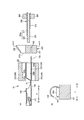
- FIG. 2 is a longitudinal sectional view of the wire crimping device 10 for explaining the female crimp terminal 100, the covered wire 200, and the wire crimping device 10.
- the wire crimping apparatus 10 includes a wire crimping unit 300 that crimps and connects the crimping portion 120 and the covered wire 200, a guide unit 410 that guides insertion of the covered wire 200 into the insertion space 120a, The electric wire 200 is held, and the electric wire holding unit 500 that inserts the covered electric wire 200 into the crimping portion main body 122 is configured.
- the electric wire crimping unit 300 is constituted by a pressing upper blade (crimper) 310 and a pressing lower blade (anvil) 320 that are divided into upper and lower parts and moves in the vertical direction (opposite direction of the pressing upper blade 310 and the pressing lower blade 320). It has a function of pressing the pressure-bonding portion main body 122 in the vertical direction with the pressing upper blade 310 and the pressing lower blade 320.
- the pressing upper blade 310 and the pressing lower blade 320 are arranged so as to face each other in the vertical direction with a predetermined interval therebetween, and when they are combined in the vertical direction, the female crimp terminal 100 and the covered electric wire 200 are crimped. Is formed into an inner surface shape corresponding to the outer shape of the crimping portion 120.
- the guide unit 410 is configured to be divided into upper and lower parts, and is arranged in a state of being separated so as to be opposed in the vertical direction, and is predetermined on the base end side Xb in the longitudinal direction X with respect to the wire crimping unit 300. They are arranged at intervals.
- the guide unit 410 is composed of an upper guide part 411 and a lower guide part 412 that are divided into two parts in the upper and lower directions.
- An internal hollow shape having an inner surface arranged in this order from the side Xa is formed.
- the guide tip portion 413 can be mounted on the outer surface of the crimping portion main body 122, and the tip portion Xa of the guide taper portion 414 has a portion a in FIG.
- the diameter of the crimping portion main body 122 is reduced by the thickness of the guide tip portion 413, and the inner diameter is approximately the same as the inner diameter of the crimping portion 120.
- a tapered tip 414a may be formed to have a diameter smaller than the inner diameter of the crimping portion 120 as long as the wire tip end portion 200a can be inserted.
- compression-bonding part 120 contacts is comprised in the front end side Xa of the taper front-end
- the guide unit 410 is configured to move and combine in the longitudinal direction X and the vertical direction from the vertically divided state.
- the guide unit 410 has an inner surface that forms the guide taper portion 414 so that the covered wire 200 is smoothly inserted without being caught by the guide taper portion 414 when the covered wire 200 is guided to the insertion space 120a. Is formed of a smooth tapered curved surface.
- the electric wire gripping unit 500 is arranged on the base end side Xb in the longitudinal direction X with respect to the guide unit 410 and is configured to be movable in the longitudinal direction X.
- the electric wire gripping unit 500 is formed to have a diameter that prevents the covered electric wire 200 from moving relative to the electric wire holding unit 500 in a state where a predetermined position of the covered electric wire 200 is held.
- the electric wire crimping unit 300, the guide unit 410, and the electric wire gripping unit 500 are independent mechanisms without being interlocked with each other.
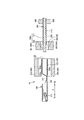
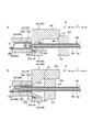
- FIGS. 3 and 4 are longitudinal sectional views of the wire crimping apparatus 10 for explaining a guide mounting process in which the guide unit 410 is mounted on the crimping portion 120
- FIG. 3B is a diagram showing a wire in the insertion space 120a.
- Fig.4 (a) is a state before the crimping connection process which crimp-connects the crimping
- Fig. 4 (b) is a longitudinal sectional view of the wire crimping device 10 for explaining the state after the crimping connection step for crimping the crimping portion 120 and the wire tip portion 200a. Is shown.
- the wire crimping method includes a guide mounting step of mounting the guide unit 410 on the female crimp terminal 100, a wire insertion step of inserting the wire tip portion 200a into the insertion space 120a, and crimping the female crimp terminal 100 and the covered wire 200.
- the crimping connection process to connect is performed in this order.
- the wire crimping device 10 starts the guide mounting process when the female crimp terminal 100 is disposed at a predetermined position.
- the wire crimping device 10 is configured such that the guide tip portion 413 of the guide unit 410 is connected to the base of the crimping portion main body 122 in a state where the upper guide portion 411 and the lower guide portion 412 are moved in the longitudinal direction X and the vertical direction. It is mounted so as to be inserted into the end side Xb.
- the wire crimping apparatus 10 starts the wire insertion process as shown in FIG. Specifically, the wire crimping device 10 moves the wire gripping unit 500 that grips a predetermined position of the covered wire 200 to the distal end side Xa in the longitudinal direction X by a predetermined distance. At this time, the wire crimping device 10 passes the wire tip portion 200 a of the covered wire 200 in the order of the guide unit 410 and the wire insertion port 123 and inserts the wire tip portion 200 a into the insertion space 120 a of the crimp portion 120 in the female crimp terminal 100.
- the electric wire tip 120a is guided along the inner surface of the guide unit 410, that is, the guide taper portion 414. Then, it is inserted into the insertion space 120 a of the crimping part 120. Thereafter, the electric wire crimping apparatus 10 moves the guide unit 410 in the longitudinal direction X and the vertical direction to separate the guide unit 410 from the female crimp terminal 100 and return it to the initial position.
- the wire crimping apparatus 10 starts a crimp connection process as shown in FIG.
- the wire crimping device 10 includes a pressing upper blade 310 of the wire crimping unit 300 and a pressing force so as to sandwich the crimping portion 120 of the female crimping terminal 100 into which the wire tip 200a of the covered wire 200 is inserted.
- the lower blade 320 is moved toward the crimping portion 120, and the crimping portion 120 is pressed by the pressing upper blade 310 and the pressing lower blade 320, so that the crimping portion 120 is plastically deformed and the wire tip portion 200a is crimped and connected. .
- the wire crimping apparatus 10 moves the wire crimping unit 300 and the wire gripping unit 500 in the longitudinal direction X and the vertical direction, and is separated from the female crimp terminal 100. To return to the initial position.
- the electric wire crimping apparatus 10 can easily insert the electric wire distal end portion 200a into the insertion space 120a by making the guide unit 410 into a divided structure and attaching the guide unit 410 to the proximal end Xb of the crimping portion 120.
- the guide unit 410 includes a guide distal end portion 413 that can be mounted on the proximal end side Xb of the crimping portion 120, a guide taper portion 414 that is configured by a tapered smooth curved surface, and the guide taper. It is comprised with the taper front-end
- the guide unit 410 is configured such that the guide tip portion 413 is joined to the crimp portion in a state where the upper guide portion 411 and the lower guide portion 412 are combined so that the taper tip portion 414a abuts on the edge portion of the wire insertion port 123 in the crimp portion 120. 120 can be attached to the base end side Xb. Thereby, the guide unit 410 can position correctly with respect to the female crimp terminal 100, and can insert the electric wire front-end
- the guide unit 410 can cover the edge of the electric wire insertion port 123 by a taper tip portion 414 a formed to have an inner diameter substantially the same as the inner diameter of the crimping portion 120 abutting against the edge of the electric wire insertion port 123.
- the wire crimping device 10 accurately fixes the position of the guide unit 410 with respect to the female crimp terminal 100 by the guide tip 413, and the wire tip 200a is fixed by the guide taper 414 and the taper tip 414a.
- the wire tip portion 200a can be smoothly and reliably inserted into the insertion space 120a without being caught by the inner surface of the guide taper portion 414 or the edge portion of the wire insertion port 123.
- the wire crimping apparatus 10 can separate the guide unit 410 by making the guide unit 410 into a divided structure. For this reason, the wire crimping device 10 can easily return the guide unit 410 from the covered wire 200 inserted into the female crimp terminal 100 to the initial position after the wire insertion step.
- the guide unit 410 may be configured as a part of the mechanism of the wire crimping device 10 or may be configured as a separate part independent of the wire crimping device 10.
- the wire crimping unit 300, the guide unit 410, and the wire gripping unit 500 are not limited to independent mechanisms without being linked to each other.
- FIG.17 (a) shows the longitudinal cross-sectional view of the electric wire crimping apparatus 10 explaining the mode before a guide mounting process
- FIG.17 (b) shows the electric wire crimping apparatus 10 explaining the mode after a guide mounting process
- FIG. FIG. 18A shows a longitudinal cross-sectional view of the wire crimping apparatus 10 for explaining the state during the wire insertion process
- FIG. 18B shows a longitudinal cross-section of the wire crimping apparatus 10 for explaining the state after the wire insertion process
- FIG. 18A is a longitudinal sectional view of the wire crimping apparatus 10 for explaining the state after the crimping connection step.
- the wire crimping apparatus 10 has the wire crimping unit 300, the guide unit 410, and the wire gripping unit 500 arranged at the initial position.
- the wire crimping device 10 moves the pressing upper blade 310 from the crimping unit initial position P0 to the first intermediate position P1, as described above.
- the guide unit 410 is moved to a position where the guide front end portion 413 is attached to the base end side Xb of 122.
- the wire crimping apparatus 10 moves the wire tip 200a of the covered wire 200 while moving the pressing upper blade 310 from the first intermediate position P1 to the second intermediate position P2. As described above, it is inserted into the insertion space 120a of the crimping part 120.
- the wire crimping apparatus 10 moves the guide unit 410 as described above while moving the pressing upper blade 310 from the second intermediate position P2 to the third intermediate position P3. Return to the initial position.
- the wire crimping apparatus 10 moves the pressing upper blade 310 to the crimping position PP for crimping the crimping portion main body 122 and the covered electric wire 200 and moves the pressing lower blade 320. Move to the crimping position PP. Finally, the wire crimping apparatus 10 returns the wire crimping unit 300 and the wire gripping unit 500 to the initial positions as shown in FIG.
- the guide mounting step, the wire inserting step, and the crimping connection step can be smoothly performed by the guide unit 410 and the wire gripping unit 500 being interlocked with the vertical movement of the wire crimping unit 300.
- the female crimp terminal 100, the wire crimping device 10, and the wire crimping method in other embodiments will be described.
- the structure of the wire crimping device 10 and the female crimp terminal 100 when crimping and connecting the female crimp terminal 100 and the covered wire 200 will be described with reference to FIGS. 5 and 6.
- FIG. 5 shows a plan view of the terminal coupling band 100a and the covered electric wire 200
- FIG. 6A shows the female crimp terminal 100, the covered electric wire 200, and the electric wire crimping apparatus 10 for explaining the electric wire crimping apparatus 10.
- a longitudinal sectional view is shown
- FIG. 6B is a sectional view taken along the line AA in FIG.
- the end surface on the base end side Xb of the wire crimping unit 300 and the end surface on the distal end side Xa of the guide cutting unit 420 are illustrated separately.
- the end face on the base end side Xb and the end face on the front end side Xa of the guide cutting unit 420 are slidably in contact with each other.
- the same components as those in the first embodiment described above are denoted by the same reference numerals, and detailed description thereof is omitted.
- a plurality of female crimp terminals 100 are connected to a substantially band-shaped carrier 124 whose longitudinal direction is the width direction Y of the female crimp terminal 100 to form a terminal coupling band 100a.
- the terminal connecting band 100 a is arranged so that the longitudinal direction X of the female crimp terminal 100 substantially coincides with the carrier short direction perpendicular to the carrier longitudinal direction of the carrier 124 in plan view.
- the rear side of the crimping part 120 in the female crimp terminal 100 is connected to the carrier 124 via the connecting part 124a, and a plurality of female crimps are provided at predetermined intervals in the carrier longitudinal direction of the carrier 124, that is, in the width direction Y.
- the terminal 100 is connected.
- the terminal connection band 100a is a three-dimensional terminal formed on a base material formed in a shape in which a substantially flat base material is punched and a substantially belt-like carrier 124 is connected to a terminal shape portion developed in a plane. By bending into a shape, a plurality of female crimp terminals 100 are connected.
- the electric wire crimping device 10 guides the insertion of the covered electric wire 200 into the electric wire crimping unit 300 and the crimping portion 120, and separates the female crimping terminal 100 and the carrier 124. And the electric wire gripping unit 500.
- the guide cutting unit 420 is arranged on the base end side Xb in the longitudinal direction X with respect to the electric wire crimping unit 300 and is configured to be movable in the vertical direction. Specifically, the guide cutting unit 420 is integrally formed with a carrier cut portion 421 that separates the female crimp terminal 100 and the carrier 124 and a guide portion 422 that guides insertion of the covered electric wire 200 into the crimp portion main body 122. is doing.
- the carrier cut part 421 has a substantially rectangular cross section and is formed in a shape having a sandwiching part 423 through which the carrier 124 is inserted.
- the guide portion 422 is integrally formed so as to be placed above the carrier cut portion 421 and has a substantially C-shaped cross section when viewed from the longitudinal direction X.
- the guide portion 422 is formed in an internal hollow having a tapered inner surface shape similar to the guide tapered portion 414 in the guide unit 410 in the first embodiment described above, and one side surface in the width direction Y is elongated. It is formed in a shape having an opening 424 that opens along the direction X and allows insertion of the covered electric wire 200.
- the guide opening 422a that opens on the distal end side Xa of the guide part 422 is formed with an opening diameter that is substantially the same as the inner diameter of the crimping part 120.
- the guide part 422 is integrally formed so that the lower part may be arrange
- the guide cutting unit 420 starts from the initial position where the sandwiching part 423 of the carrier cut part 421 waits on the carrier longitudinal direction of the terminal connection band 100a, that is, the flow line of the carrier 124 in the width direction Y.
- the side Xa is configured to be movable in the vertical direction to a position facing the wire insertion port 123 of the crimping portion 120 in the longitudinal direction X.
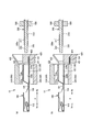
- 7A is a longitudinal sectional view of the wire crimping device 10 for explaining a state in the middle of the carrier cutting process in which the female crimp terminal 100 and the carrier 124 are separated by the guide cutting unit 420
- FIG. 8 is a longitudinal sectional view of the electric wire crimping apparatus 10 for explaining a state at the completion of the carrier cutting process in which the female crimp terminal 100 and the carrier 124 are separated by the guide cutting unit 420
- FIG. The longitudinal cross-sectional view of the electric wire crimping apparatus 10 explaining the mode of the electric wire insertion process which inserts 200a is shown.
- the end surface on the base end side Xb of the wire crimping unit 300 and the end surface on the front end side Xa of the guide cutting unit 420 are illustrated slightly apart so that each component can be easily understood. However, the end face on the base end side Xb of the electric wire crimping unit 300 and the end face on the front end side Xa of the guide cutting unit 420 are slidably in contact with each other.
- the carrier cutting step for separating the female crimp terminal 100 and the carrier 124, the wire insertion step, and the crimp connection step are performed in this order.
- the wire crimping device 10 starts the carrier cutting process when the female crimp terminal 100 is disposed at a predetermined position.
- the wire crimping device 10 inserts the carrier 124 of the terminal coupling band 100a through the sandwiching portion 423 of the guide cutting unit 420 disposed at the initial position. Thereafter, as illustrated in FIG. 7B, the wire crimping device 10 is configured to reach a position where the distal end side Xa of the guide portion 422 of the guide cutting unit 420 faces the wire insertion port 123 of the crimp portion 120 in the longitudinal direction X. The guide cutting unit 420 is moved downward. At this time, the carrier cut part 421 cuts the carrier 124 so as to be sheared by the sandwiching part 423 to separate the female crimp terminal 100 from the terminal connection band 100a.
- the wire crimping device 10 starts the wire insertion step as shown in FIG. Specifically, the wire crimping device 10 moves the wire gripping unit 500 that grips a predetermined position of the covered wire 200 to the distal end side Xa in the longitudinal direction X by a predetermined distance. At this time, the wire crimping device 10 allows the wire tip portion 200a of the covered wire 200 to pass through the guide opening portion 422a of the guide portion 422 and the wire insertion port 123 in this order, and the insertion space of the crimp portion 120 in the female crimp terminal 100. Insert into 120a.
- the wire tip portion 120 a is guided along the inner surface of the guide cutting knit 420 and the crimping portion 120. Is inserted into the insertion space 120a.
- the electric wire crimping apparatus 10 starts a crimp connection process as shown in FIG.
- the wire crimping device 10 includes a pressing upper blade 310 of the wire crimping unit 300 and a pressing force so as to sandwich the crimping portion 120 of the female crimping terminal 100 into which the wire tip 200a of the covered wire 200 is inserted.
- the lower blade 320 is moved toward the crimping portion 120, and the crimping portion 120 is pressed by the pressing upper blade 310 and the pressing lower blade 320, so that the crimping portion 120 is plastically deformed and the wire tip portion 200a is crimped and connected.
- the wire crimping device 10 moves the wire 1 with crimp terminal in the width direction Y, and causes the covered wire 200 to escape from the wire crimping device 10 through the opening 424 of the guide portion 422.
- the wire crimping apparatus 10 moves the wire crimping unit 300, the guide cutting unit 420, and the wire gripping unit 500 in the longitudinal direction X and the vertical direction to the initial position. return.
- the wire crimping device 10 can smoothly perform the carrier cutting step and the wire inserting step by integrally forming the guide cutting unit 420 so that the guide portion 422 is placed on the upper plane of the carrier cutting portion 421. it can.
- the wire crimping device 10 lowers the guide cutting unit 420 from the initial position to a position where the wire insertion port 123 on the proximal end side Xb of the crimping portion 120 and the distal end side Xa of the guide portion 422 face each other in the carrier cutting process.
- the guide part 422 is made to stand by by moving in the direction.
- the electric wire crimping device 10 can immediately insert the electric wire tip portion 200a into the insertion space 120a with respect to the guide portion 422 of the guide cutting unit 420 that has completed the carrier cutting step, so that the electric wire insertion step can be smoothly performed. Can be migrated.
- the wire crimping device 10 has the guide portion 422 formed with an opening 424 that allows the covered wire 200 to escape along the longitudinal direction X, that is, in a substantially C-shaped cross section when viewed from the longitudinal direction X. After the crimping step, the covered electric wire 200 crimped and connected to the female crimp terminal 100 can be easily escaped through the opening 424 of the guide portion 422.
- the wire crimping device 10 includes a guide cutting unit 420 that is integrally formed so as to be disposed below the guide portion 422 on the upper surface of the carrier cut portion 421 (see FIG. 6), whereby the guide portion and the carrier cut portion are provided. And a wire crimping device configured separately from each other, the number of parts can be reduced, and the mechanism of the device can be simplified.
- FIG. 9 shows a longitudinal sectional view of the wire crimping device 10 for explaining the female crimp terminal 100, the covered wire 200, and the wire crimping device 10.
- the same components as those in the first embodiment described above are denoted by the same reference numerals, and detailed description thereof is omitted.
- the electric wire crimping apparatus 10 includes an electric wire crimping unit 300, a guide unit 430, and an electric wire gripping unit 500.
- the guide unit 430 is configured to be divided into upper and lower parts, arranged in a state of being separated so as to face each other in the vertical direction, and the end surface of the distal end side Xa is aligned with the end surface of the proximal end side Xb of the wire crimping unit 300. It is arranged to touch.
- the guide unit 430 includes an upper guide part 431 and a lower guide part 432 that are divided into two parts in the vertical direction, and in the state where the upper guide part 431 and the lower guide part 432 are combined in the vertical direction, A diameter approximately the same as the inner diameter of 122 is formed into an internal hollow shape having a tapered inner surface whose diameter is expanded from the distal end side Xa toward the proximal end side Xb.
- the guide unit 430 is configured to move in the up and down direction from the vertically divided state and combine. In addition, you may comprise so that the electric wire crimping unit 300 may interlock
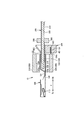
- FIG. 10A shows a longitudinal sectional view of the wire crimping apparatus 10 for explaining a guide moving step of moving the inner diameter of the guide unit 430 to a position opposite to the inner diameter of the crimping portion 120.
- FIG. ) Shows a longitudinal sectional view of the wire crimping apparatus 10 for explaining the state of the wire insertion step of inserting the wire tip portion 200a into the insertion space 120a.
- FIG. 11A shows the crimp portion 120 and the wire tip portion 200a.
- FIG. 11B is a longitudinal sectional view for explaining the state before the crimping connection process for crimping connection
- FIG. 11B is a wire crimping apparatus for explaining the state after the crimping connection process for crimping and connecting the crimping part 120 and the wire tip part 200a.
- 10 shows a longitudinal sectional view.
- the wire crimping device 10 starts the guide moving process when the female crimp terminal 100 is disposed at a predetermined position.
- the electric wire crimping device 10 inserts the inner diameter of the distal end side Xa of the guide unit 430 in which the upper guide portion 431 and the lower guide portion 432 separated in the vertical direction are combined in the vertical direction into the electric wire insertion of the crimp portion 120. It arrange
- the wire crimping apparatus 10 starts the wire insertion process as shown in FIG. Specifically, the wire crimping device 10 moves the wire gripping unit 500 that grips a predetermined position of the covered wire 200 to the distal end side Xa in the longitudinal direction X by a predetermined distance. At this time, the wire crimping device 10 passes the wire tip portion 200 a of the covered wire 200 in the order of the guide unit 410 and the wire insertion port 123 and inserts the wire tip portion 200 a into the insertion space 120 a of the crimp portion 120 in the female crimp terminal 100.
- the wire tip portion 120 a is guided along the inner surface of the guide unit 430, and It is inserted into the insertion space 120a.
- the electric wire crimping apparatus 10 starts a crimp connection process as shown in FIG. Specifically, the wire crimping device 10 further moves and presses the pressing upper blade 310 and the pressing lower blade 320 against the crimping portion 120 of the female crimp terminal 100 into which the wire tip portion 200a of the covered wire 200 is inserted. As a result, the crimping portion 120 is plastically deformed and the wire tip portion 200a is crimped and connected.
- the wire crimping device 10 moves the guide unit 430 in the vertical direction, separates the guide unit 430 from the female crimp terminal 100, and returns to the initial position.
- the wire crimping device 10 can smoothly perform the guide moving step, the wire inserting step, and the crimping connection step by adopting a configuration in which the guide unit 430 is not attached to the proximal end side Xb of the crimping portion main body 122.
- the wire crimping device 10 is configured so that the guide unit 430 is not attached to the crimping portion 120, so that the guide unit 430 moves to the crimping connection step without returning the guide unit 430 to the initial position between the guide moving step and the wire insertion step. can do.
- the electric wire crimping device 10 can smoothly move through the guide moving step, the electric wire insertion step, and the crimping connection step in this order without the need to remove the guide unit 430 before and after the electric wire insertion step.
- the guide unit of the present embodiment includes a carrier cut part 421z of the guide cutting unit of the second embodiment below the lower guide part 432z.
- the guide unit 430z in which the lower guide portion 432z and the carrier cut portion 421z are integrally formed may be used.
- FIG. 19A to FIG. 19C show how the guide unit 430z moves step by step.
- the guide unit 430z turns the guide unit 430z downward from the state in which the carrier 124 in the terminal connection band 100a is inserted into the sandwiching part 423z of the carrier cut part 421z, similarly to the guide cutting unit 420 in the second embodiment. To move and cut.
- the upper guide portion 431 starts to move downward as shown in FIG.
- the upper guide portion 431 that moves downward contacts the lower guide portion 432z in a state where the carrier 124 is inserted into the sandwiching portion 423z.
- the lower guide portion 432 is pushed by the upper guide portion 431 moving downward, moves downward integrally with the upper guide portion 431, and the carrier 124 inserted through the sandwiching portion 423z is inserted into the sandwiching portion 423z.
- the pressing lower blade 320 is pushed by the upper guide portion 431 moving downward, moves downward integrally with the upper guide portion 431, and the carrier 124 inserted through the sandwiching portion 423z is inserted into the sandwiching portion 423z.
- the guide unit 430z moves the upper guide portion 431 and the lower guide portion 432 together to a predetermined position.
- the opening portion on the distal end side Xa of the tapered inner surface of the guide unit 430z is the wire insertion port 123 of the female crimp terminal 100.
- the guide unit 430z may integrally form the upper guide portion 431 and the lower guide portion 432z.
- FIG. 12 is a longitudinal sectional view of the wire crimping device 10 for explaining the female crimp terminal 100, the covered wire 200, and the wire crimping device 10.
- the same components as those in the first embodiment described above are denoted by the same reference numerals, and detailed description thereof is omitted.
- the electric wire crimping apparatus 10 includes an electric wire crimping unit 300, a guide gripping unit 440, and an electric wire gripping unit 500.
- the guide gripping unit 440 has a configuration that is divided into two parts in the upper and lower directions, and is arranged in a state of being separated so as to face the upper direction, and at the proximal end side Xb in the longitudinal direction X with respect to the wire crimping unit 300. They are arranged at a predetermined interval.
- the guide gripping unit 440 includes an upper guide portion 441 and a lower guide portion 442 that are divided into two parts in the vertical direction, and the covered electric wire 200 is relative to the guide gripping unit 440 when combined in the vertical direction.
- the distal end Xa is a conductor gripping portion 443, and the proximal end Xb is a covering gripping portion 444.
- the guide gripping unit 440 is configured to move and combine in the longitudinal direction X and the vertical direction from the vertically divided state.
- the guide gripping unit 440 is not limited to be formed with an inner diameter that is large enough to prevent the covered electric wire 200 from moving relative to the guide gripping unit 440, but may be formed with an inner diameter that allows relative movement.
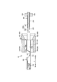
- FIG. 13A shows a longitudinal sectional view of the wire crimping device 10 for explaining a state in the middle of the wire guiding process for guiding the distal end side Xa of the wire distal end portion 200a to the wire insertion port 123, and FIG.
- FIG.14 (a) shows electric wire in the insertion space 120a.
- FIG.14 (b) is the time of completion of the electric-wire insertion process which inserts the electric wire front-end
- the longitudinal cross-sectional view of the electric wire crimping apparatus 10 explaining a mode is shown.
- the electric wire crimping method includes an electric wire guiding process for guiding the distal end side Xa of the electric wire distal end portion 200a to the electric wire insertion port 123 while grasping the electric wire distal end portion 200a by the guide grasping unit 440, an electric wire inserting step, and a crimping connecting step. Do in order.
- the wire crimping device 10 starts the wire guiding process when the female crimp terminal 100 is disposed at a predetermined position. Specifically, as shown in FIG. 13A, the electric wire crimping apparatus 10 moves the upper guide portion 441 and the lower guide portion 442 that are separated in the vertical direction in the vertical direction, thereby moving the electric wire tip portion 200a to the guide gripping unit. Grip at 440. At this time, the guide gripping unit 440 grips the wire tip end 200a so that the tip end side Xa of the conductor exposed portion 222 of the wire tip end portion 200a is slightly exposed from the tip end side Xa of the guide gripping unit 440.
- the guide grip unit 440 moves in the longitudinal direction X to the base end side Xb of the crimping section main body 122 together with the covered wire 200, and is exposed from the guide grip unit 440.
- the leading end side Xa of 200a is guided to the wire insertion port 123 of the crimping part 120.
- the electric wire crimping apparatus 10 will start an electric wire insertion process, as shown in FIG. Specifically, when the wire crimping device 10 guides the distal end side Xa of the wire distal end portion 200a to the wire insertion port 123, the guide gripping unit 440 is separated vertically and the gripping of the covered wire 200 by the guide gripping unit 440 is released. Then, the electric wire holding unit 500 holding the predetermined position of the covered electric wire 200 is moved by a predetermined distance toward the distal end side Xa in the longitudinal direction X.
- the wire crimping device 10 passes the wire tip portion 200a of the covered wire 200 through the guide gripping unit 440 and the wire insertion port 123 in this order, and inserts into the insertion space 120a of the crimping portion 120 of the female crimp terminal 100. .
- the electric wire crimping apparatus 10 starts a crimp connection process as shown in FIG.
- the wire crimping device 10 includes a pressing upper blade 310 of the wire crimping unit 300 and a pressing force so as to sandwich the crimping portion 120 of the female crimping terminal 100 into which the wire tip 200a of the covered wire 200 is inserted.
- the lower blade 320 is moved toward the crimping portion 120, and the crimping portion 120 is pressed by the pressing upper blade 310 and the pressing lower blade 320, so that the crimping portion 120 is plastically deformed and the wire tip portion 200a is crimped and connected. .
- the wire crimping apparatus 10 moves the wire crimping unit 300, the guide gripping unit 440, and the wire gripping unit 500 in the longitudinal direction X and the vertical direction, thereby crimping the female die. It is separated from the terminal 100 and returned to the initial position.
- the electric wire front end portion 200a is gripped so that the front end side Xa of the conductor exposed portion 222 of the electric wire front end portion 200a is slightly exposed from the front end side Xa of the guide holding unit 440.
- the wire tip 200a may be gripped so that the tip Xa of the conductor exposed portion 222 is not exposed from the tip Xa of the guide gripping unit 440.
- the wire crimping device 10 smoothly performs the wire guiding step and the wire inserting step by guiding the distal end side Xa of the wire distal end portion 200a to the wire insertion port 123 while the guide gripping unit 440 grips the wire distal end portion 200a. It can be carried out.
- the wire crimping device 10 slightly exposes the distal end side Xa of the wire distal end portion 200a from the distal end portion Xa of the guide gripping unit 440 when the guide gripping unit 440 grips the distal end side Xa of the electrical wire distal end portion 200a.
- the exposed portion of the distal end side Xa of the electric wire distal end portion 200a can be directly guided to the electric wire insertion port 123, and the transition to the electric wire insertion process can be smoothly performed by releasing the grip of the covered electric wire 200.
- the guide gripping unit 440 is moved in a state where the end surface on the distal end side Xa of the conductor exposed portion 222 coincides with the end surface on the distal end side Xa of the guide gripping unit 440 or enters the base end side Xb. After the movement, the electric wire distal end portion 200a may be moved to the distal end side Xa and inserted into the insertion space.
- FIG. 15A is a longitudinal sectional view of the wire crimping device 10 for explaining the female crimp terminal 100, the covered wire 200, and the wire crimping device 10.
- the same configurations as those in the above-described embodiment are denoted by the same reference numerals, and detailed description thereof is omitted.
- the electric wire crimping apparatus 10 includes an electric wire crimping unit 300, a guide cutting unit 450, and an electric wire gripping unit 510.
- the guide cutting unit 450 has an upper guide part 451 and a lower cutting part 452 that are divided into two parts in the vertical direction so that the end face of the distal end side Xa is in contact with the end face of the proximal end side Xb of the wire crimping unit 300. It is configured to be arranged and movable in the vertical direction.
- This guide cutting unit 450 is formed in an internal hollow shape in a state where the upper guide portion 451 and the lower cut portion 452 are combined in the vertical direction.
- the guide cutting unit 450 includes a conductor insertion portion 450a having a diameter substantially the same as the outer diameter of the conductor exposed portion 222 and slightly extending along the longitudinal direction X, and a proximal end side of the conductor insertion portion 450a.
- a tapered guide surface 453 in which the diameter of Xb is expanded from the distal end side Xa toward the proximal end side Xb is formed in an internal hollow shape having this order.
- the upper guide portion 451 is provided with a slide portion 454 that protrudes from the upper end toward the base end side Xb in the longitudinal direction X.
- the slide portion 454 is provided with a slide surface 455 formed by chamfering the lower end of the base end side Xb by 45 °.
- the lower cut portion 452 is formed with an opening along the width direction Y and a pinching portion 423 that allows the carrier 124 to be inserted into the terminal connection band 100a. Further, the lower cutting portion 452 is configured to be movable downward or upward in conjunction with the upward or downward movement of the upper guide portion 451.
- the sandwiching portion 423 of the lower cutting portion 452 is positioned on the flow line of the carrier 124 in the carrier longitudinal direction of the connecting terminal band 100a, that is, in the width direction Y.
- the standby position is an initial state, and the conductor insertion portion 450a of the guide cutting unit 450 is configured to be movable from the standby position to a position facing the wire insertion port 123 of the crimping portion 120.
- the wire gripping unit 510 has a slide surface 511 formed by chamfering the upper end of the tip side Xa facing the slide surface 455 in the longitudinal direction X by 45 ° with respect to the wire gripping unit 500 in the first embodiment described above. The difference is that it is provided.
- the electric wire crimping device 10 will be described in detail later, but the electric wire gripping unit 510 and the upper guide portion 451 are combined in the vertical direction as the electric wire gripping unit 510 moves to the distal end side Xa in the longitudinal direction X.
- the upper guide part 451 and the lower cutting part 452 are configured to slide so as to be separated in the vertical direction.
- FIG. 15B is a longitudinal sectional view of the wire crimping device 10 for explaining the state at the completion of the carrier cutting process in which the female crimping terminal 100 and the carrier 124 are separated by the guide cutting unit 450.
- FIG. ) Shows a longitudinal cross-sectional view of the wire crimping device 10 for explaining a state in the middle of the wire insertion process for guiding the distal end side Xa of the wire distal end portion 200a to the wire insertion port 123
- FIG. The longitudinal cross-sectional view of the electric wire crimping apparatus 10 explaining the mode at the time of the electric wire insertion process completion which guides the front end side Xa to the electric wire insertion port 123 is shown.
- the carrier cutting step for separating the female crimp terminal 100 and the carrier 124, the wire insertion step, and the crimp connection step are performed in this order.
- the wire crimping device 10 starts the carrier cutting process when the female crimp terminal 100 is disposed at a predetermined position.
- the electric wire crimping device 10 is connected to the guide cutting unit 450 that has been moved downward from the standby position by the pinching portion 423, as in the carrier cutting step in the second embodiment.
- the female crimp terminal 100 is separated from the band 100a.
- the guide cutting unit 450 moves to a position where the conductor insertion portion 450 a faces the wire insertion port 123.
- the wire crimping apparatus 10 starts the wire insertion process as shown in FIG. Specifically, the wire crimping apparatus 10 moves the wire gripping unit 510 that grips a predetermined position of the covered wire 200 to the distal end side Xa in the longitudinal direction X as shown in FIG. The exposed portion 222 is inserted into the conductor insertion portion 450a of the guide cutting unit 450.
- the electric wire tip portion 200a is guided along the guide surface 453 of the guide cutting unit 450 to be a conductor. Inserted in the insertion portion 450a, the vicinity of the tip end side Xa of the conductor exposed portion 222 is positioned in the insertion space 120a.
- the wire crimping device 10 separates the upper guide portion 451 and the lower cutting portion 452 in the vertical direction by the slide mechanism, and inserts the insulating coating tip portion 211 of the wire tip portion 200a into the insertion space 120a.
- the slide surface 511 of the electric wire gripping unit 510 comes into contact with the slide surface 455 of the upper guide portion 451 in the guide cutting unit 450 as the movement in the longitudinal direction X occurs. Is further moved in the longitudinal direction X, the slide surface 511 moves the upper guide portion 451 upward. Further, when the upper guide portion 451 starts to move upward, the lower cutting portion 452 starts moving downward in conjunction with the movement of the upper guide portion 451.
- the wire crimping apparatus 10 moves the upper guide portion 451 and the lower cutting portion 452 combined in the vertical direction upward and downward, respectively, and moves the slide portion 454 of the upper guide portion 451 with the wire gripping unit 510.
- tip part 200a is comprised.
- the wire crimping device 10 When the upper guide portion 451 and the lower cutting portion 452 start separation in the vertical direction, the wire crimping device 10 further moves the wire gripping unit 510 to the distal end side Xa in the longitudinal direction X as shown in FIG. Then, the insulating coating tip portion 211 of the wire tip portion 200a is inserted into the insertion space 120a through the space formed by the separation of the upper guide portion 451 and the lower cutting portion 452.
- the wire crimping device 10 When the covered electric wire 200 is inserted into the female crimp terminal 100, the wire crimping device 10 starts a crimp connection step similar to the crimp connection step in the second embodiment, and crimps the crimp portion 120 and the wire tip portion 200a. It connects and comprises the electric wire 1 with a crimp terminal.
- the wire crimping apparatus 10 moves the wire crimping unit 300 in the vertical direction toward the standby position, and then directs the wire gripping unit 510 that grips the wire 1 with the crimp terminal toward the proximal end Xb in the longitudinal direction X.
- the electric wire 1 with a crimping terminal is discharged from the electric wire crimping device 10 by being moved.
- the guide cutting unit 450 separated in the vertical direction by the electric wire gripping unit 510 moves downward with the movement of the upper guide portion 451 as the upper guide portion 451 moves downward as the electric wire gripping unit 510 moves.
- the part 452 moves upward and combines in the vertical direction.
- the wire crimping device 10 moves the guide cutting unit 450 to the standby position.
- the effect of the electric wire crimping apparatus 10 comprised above and the electric wire crimping method is demonstrated.
- the carrier cutting step and the electric wire insertion step can be performed smoothly.
- the wire crimping apparatus 10 is in a state where the conductor insertion portion 450a of the upper guide portion 451 waits at a position facing the wire insertion port 123 of the crimping portion 120 in a state where the carrier cutting process is completed. Smooth transition to the process.
- the wire crimping apparatus 10 is provided with a slide mechanism, the upper guide portion 451 and the lower cutting portion 452 can be separated while guiding the covered wire 200, so that the covered wire 200 can be crimped more efficiently. It can be inserted into the terminal 100.
- the electric wire 1 with the crimp terminal can be easily discharged from the electric wire crimping apparatus 10 after the crimping connection process is completed.
- the crimp terminal of the present invention corresponds to the female crimp terminal 100 of the embodiment
- the conductor corresponds to the aluminum conductor 220
- the crimping means corresponds to the wire crimping unit 300
- the guide means corresponds to the guide units 410 and 430, the guide part 422, and the guide cutting unit 450
- the guide portions correspond to the upper guide portions 411, 431, 441, 451, the lower guide portions 412, 432, 442, and the lower cut portion 452
- the carrier cutting means corresponds to the carrier cutting part 421 and the lower cutting part 452
- the allowance for withdrawal corresponds to the opening 424.
- the guide gripping means corresponds to the guide gripping unit 440
- the moving means corresponds to the electric wire gripping units 500 and 510
- the terminal axis direction corresponds to the longitudinal direction X
- the carrier longitudinal direction corresponds to the width direction Y
- the present invention is not limited only to the configuration of the above-described embodiment, and many embodiments can be obtained.
- the present invention is not limited to the female crimp terminal 100 having the box portion 110 but may be a male crimp terminal having a connection tab or a crimp terminal constituted only by the crimp portion 120.
- the female crimp terminal of the present invention is not limited to the same inner diameter of the conductor crimping part 122a and the inner diameter of the coated crimping part 122b, but as shown in FIGS. 20 (a) to 20 (c).
- the female crimp terminal 1000 may be formed in a stepped shape such that the inner diameter of the coated crimp portion 1220b is larger than the inner diameter of the conductor crimp portion 1220a.
- FIG. 20A shows a perspective view of the female crimp terminal 1000
- FIG. 20B shows a longitudinal sectional view of the wire crimping apparatus 10 for explaining the state after the wire insertion step
- FIG. c) has shown the longitudinal cross-sectional view of the electric wire crimping apparatus 10 explaining the mode after a crimping connection process.
- FIG. 21A shows a plan view of a state where the core rod 600 is placed on the crimping portion equivalent portion 1201
- FIG. 21B shows a cross-sectional view taken along the line BB in FIG. 21A.
- FIG. 21 (c) is a longitudinal sectional view showing a state where the crimping part 1200 is formed in a hollow shape
- FIG. 21 (d) is a sectional view taken along the line CC in FIG. 21 (c). .
- the crimping portion main body 1220 is formed by forming the conductor crimping portion 1220a substantially equal to or slightly larger than the outer diameter of the conductor exposed portion 222.
- the portion 1220b is formed to be approximately equal to or slightly larger than the outer diameter of the insulating coating tip portion 211.
- the stepped portion 1220z in the crimping portion main body 1220 is not a stepped shape that is orthogonal to the longitudinal direction X, but is formed in a stepped shape that is smooth from the coated crimped portion 1220b to the conductor crimped portion 1220a.
- the terminal base material is punched into a shape in which a hollow crimp section 1200 formed in a step shape is developed in a plane.
- the step portion 620 of the core rod 600 is a step portion of the crimping portion 1200 as shown in FIG.
- the core rod 600 is placed on the terminal base material so as to be positioned at the stepped portion equivalent portion 1221z corresponding to 1220z.
- the crimping portion equivalent portion 1201 corresponding to the crimping portion 1200 is bent at both ends in the width direction Y around the core rod shaft 610 as shown in FIG. And as shown in FIG.21 (d), it forms in a hollow shape so that the core rod 600 may be surrounded with the press die which is not shown in figure.
- FIGS. 22 and 23 show a cross-sectional view of the conductor crimping portion 1220a after the crimping connection step when the crimping portion main body 1220 has a stepped shape
- FIG. 23 shows the case where the crimping portion main body 122 is not formed in a stepped shape. Sectional drawing of the conductor crimping
- the gap between the conductor crimping portion 1220a and the conductor exposed portion 222 in the crimp portion main body 1220 formed in the step shape is compared with the gap between the conductor crimping portion 122a and the conductor exposed portion 222 in the crimp portion main body 122 not formed in the step shape. Therefore, the conductor crimping portion 122a has a small amount of displacement inward in the radial direction in the crimping portion main body 1220 when crimped and connected to the conductor exposed portion 222, and can prevent the occurrence of surplus.
- the conventional crimped part main body 122 that is not formed in a stepped shape has a larger gap between the conductor crimped part 122a and the conductor exposed part 222 than the crimped part main body 1220 formed in a stepped shape.
- the conductor crimping part 122a has a large amount of displacement inward in the radial direction in the crimping part main body 122 when crimped and connected to the conductor exposed part 222.
- the conventional conductor crimping portion 122a has a large amount of displacement inward in the radial direction in the crimping portion main body 122, so that a surplus is generated when crimping the conductor exposed portion 222. As shown in FIG. An inwardly-turned portion 120z that protrudes so that the surplus thickness falls inward in the radial direction at 122 is generated.
- the inwardly tilted portion 120z becomes an obstacle, and the conductor exposed portion 222 does not reach the corner of the conductor crimping portion 122a. As shown in the enlarged view of FIG. 23, there is a possibility that a gap is generated between the conductor crimping portion 122a and the conductor exposed portion 222.
- the electrical connectivity deteriorates or the capillary phenomenon occurs. As a result, moisture penetrates and the electrical characteristics deteriorate.
- the crimp part main body 1220 formed in the step shape has a smaller gap between the conductor crimp part 1220a and the conductor exposed part 222 than the crimp part main body 122 not formed in the step shape. Even if the tip end portion 200a is crimped and connected, the conductor crimping portion 1220a and the conductor exposed portion 222 are crimped without causing the inwardly-turned portion 120z in the conductor crimping portion 1220a, thereby deteriorating the electrical characteristics. Can be prevented.
- the stepped portion 1220z in the crimped portion main body 1220 is formed in a stepped shape that becomes smooth from the coated crimped portion 1220b to the conductor crimped portion 1220a, the wire tip portion 200a can be easily inserted into the insertion space 1200a. Can do.
- the female crimp terminal 1000 as described above is manufactured by using the core rod 600, the position of the stepped portion 1220z in the crimp portion main body 1220 can be adjusted even if the female crimp terminal 1000 is mass-produced.
- the crimp terminals 1000 can be formed at desired positions without variations.
- the crimping portion main body As described above, the gap between the conductor crimping portion and the conductor exposed portion 222, and the covering Since the gap between the crimping portion and the insulating coating tip portion 211 is formed in a step shape so as to be small, when the electric wire tip portion 200a is inserted into the insertion space, the insulating coating tip portion 211 is formed on the step portion of the crimping portion main body. May be caught and the wire tip 200a may not be securely inserted into the insertion space.
- the coated crimping part is formed longer than the desired length in the longitudinal direction X, even if the tip of the conductor exposed part 222 hits the tip of the crimped part body, the stepped portion of the crimped part body is insulated. By continuing to insert the wire tip portion 200a until the tip portion 211 hits, the tip of the conductor exposed portion 222 may be bent.
- the covering crimping portion is formed longer than the desired length in the longitudinal direction X, even if the insertion of the wire tip portion 200a is stopped immediately before the tip of the conductor exposed portion 222 hits the tip of the crimping portion main body 1220.
- the covering crimping portion is located around the portion on the base end side Xb of the conductor exposed portion 222.
- the gap between the conductor exposed portion 222 and the crimped portion main body on the base end side Xb is larger than the gap between the conductor exposed portion 222 and the crimped portion main body on the distal end side Xa. That is, the conductor crimping portion in this case may form the inwardly-turned portion 120z when being crimped and connected to the conductor exposed portion 222.
- the insertion of the wire tip portion 200a into the insertion space 1200a is insufficient, the tip of the conductor exposed portion 222 is bent, Can insert the wire tip portion 200a at a desired position with respect to the insertion space 1200a without increasing the gap between the conductor crimping portion 1220a and the conductor exposed portion 222.
- the desired position is a position in the longitudinal direction X where the boundary portion between the conductor exposed portion 222 and the coating tip portion 211 corresponds to the step portion 1220z of the crimping portion main body 1220.
- the crimping part main body 1220 and the wire tip part 200a are formed by accurately matching the stepped part equivalent part 1221z of the crimping part equivalent part 1201 and the stepped part 620 of the core rod 600 to form the crimping part 1200 in a hollow shape.
- the female crimp terminal 1000 formed in a stepped shape as described above is provided with a wire toward the center of the wire insertion port by the guide units 410 and 430, the guide cutting units 420 and 450, the guide gripping unit 440, and the like of the present invention.
- the insertion of the tip portion 200a is allowed. Thereby, it can prevent that the electric wire front-end
- the conductor crimping portion 1220a is formed to be approximately equal to or slightly larger than the outer diameter of the conductor exposed portion 222, and the coated crimping portion 1220b is approximately equal to or slightly smaller than the outer diameter of the insulating coating tip portion 211. Even if the wire tip 200a is formed in a large size, the wire tip 200a can be surely inserted into the insertion space 1200a without the aluminum wire 221 coming apart and the exposed conductor 222 being bent due to the contact of the stepped portion 1220z. Can be inserted into.
Landscapes
- Engineering & Computer Science (AREA)
- Manufacturing & Machinery (AREA)
- Manufacturing Of Electrical Connectors (AREA)
- Connections Effected By Soldering, Adhesion, Or Permanent Deformation (AREA)
Abstract
【課題】クローズドバレル形式の圧着端子における中空形状の圧着部に対して電線先端部をスムーズに挿入して、確実、且つ効率よく圧着することができる電線圧着装置、及び電線圧着方法を提供することを目的とする。 【解決手段】圧着部(120)の長手方向(X)における基端側(Xb)で開口する電線挿入口(123)から内部に電線先端部(200a)が挿入された圧着部(120)を圧着する電線圧着ユニット(300)と、該電線圧着ユニット(300)で圧着するために所定位置に配置した雌型圧着端子(100)の電線挿入口(123)へアルミニウム導体(220)の先端部を案内するガイドユニット(410)とを備え、ガイドユニット(410)の電線挿入口(123)に対向する対向部分の内径を電線挿入口(123)の内径に合わせて形成した電線圧着装置(10)を提供することができる。
Description
この発明は、帯状に形成されたキャリアと該キャリアの幅方向の少なくとも一端側から突出する複数の端子金具とで構成した端子連結帯における端子金具を、被覆電線における、先端側の絶縁被覆を剥がして導体を露出させた電線先端部に圧着接続するための電線圧着装置、及び電線圧着方法に関する。
圧着端子としては、幅方向の両側から曲げて中間部分で対向させた形態で被覆電線の先端側の絶縁被覆を剥がした電線先端部を圧着するバレル片を備えたオープンバレル型の圧着端子と、基端側で開口する挿入口から内部に電線先端部を挿入可能な中空形状に形成した圧着部を備えたクローズドバレル型の圧着端子が用いられている。
オープンバレル型の圧着端子の場合、過酷な使用環境下において圧着部は露出しているため、圧着接続部分における圧着部表面や導体表面が腐食し、導電性が低下するおそれがあった。
これに対して、クローズドバレル型の圧着端子は中空形状に形成しているため、内部に挿入した電線先端部を周方向全体において隙間なく覆うことができることから圧着端子と被覆電線の導体とを確実に導通させ、また、圧着接続部分における圧着部表面や導体表面に生じる腐食を防止することができると考えられる。
一方、このような圧着端子は、被覆電線の電線先端部を圧着端子の圧着部に配置した後、例えば、特許文献1に開示の端子圧着装置のような電線圧着装置を用いて、圧着部をかしめて電線先端部に圧着することで、被覆電線に圧着端子を接続した電線接続構造体として構成される。
しかし、クローズドバレル型の圧着端子の場合、被覆電線の電線先端部を圧着端子の圧着部に配置するためには、圧着部の基端側の挿入口から被覆電線の電線先端部を挿入する必要があるが、止水性の観点から被覆電線の外径と圧着部の内径とがほぼ等しく、つまり圧着部に挿入された電線先端部の絶縁被覆部の外周と圧着部の内周との間にほとんど隙間が形成されない径で形成しているため、電線先端部の中心と圧着部の中心とを一致させてから挿入しなければ挿入できないという課題を有していた。
そこでこの発明は、クローズドバレル形式の圧着端子における中空形状の圧着部に対して電線先端部をスムーズに挿入して、確実、且つ効率よく圧着することができる電線圧着装置、及び電線圧着方法を提供することを目的とする。
本発明は、導体を絶縁被覆で被覆し、先端側の前記絶縁被覆を剥がして前記導体を露出させた電線先端部を備えた被覆電線と、前記電線先端部の圧着接続を許容する中空形状の圧着部を備えたクローズドバレル形式の圧着端子とを、前記圧着部と前記電先端部との圧着により接続する電線圧着装置であって、前記圧着部の端子軸方向における基端側で開口する電線挿入口から内部に前記電線先端部が挿入された前記圧着部を圧着する圧着手段と、該圧着手段で圧着するために所定位置に配置した前記圧着端子の前記電線挿入口へ前記電線先端部を案内する案内手段とを備え、前記案内手段の前記電線挿入口に対向する対向部分の内径を前記電線挿入口の内径に合わせて形成したことを特徴とする。
上記導体は、素線を撚った撚線あるいは単線とすることができ、さらには、例えば、銅や銅合金で構成する圧着端子と同系金属で構成する銅系導体あるいは、圧着端子を構成する金属に対して卑な金属であるアルミニウムやアルミニウム合金などの異種金属で構成するアルミニウム系導体などとすることができる。
さらにまた、上記導体は、銅系導体の周りにアルミニウム系導体を配置した異種混合線などでもよく、逆にアルミニウム系導体の周りに銅系導体を配置した異種混合線などでもよい。
さらにまた、上記導体は、銅系導体の周りにアルミニウム系導体を配置した異種混合線などでもよく、逆にアルミニウム系導体の周りに銅系導体を配置した異種混合線などでもよい。
上述の中空形状の圧着部は、円筒状や角筒状の圧着部や、円筒状や角筒状において、前記電線挿入口と反対側の端部が封止された形状の圧着部とすることができる。
上記案内手段は、装置の一部の機構や、圧着端子や被覆電線とは異なる別部材とすることができる。
上記案内手段は、装置の一部の機構や、圧着端子や被覆電線とは異なる別部材とすることができる。
この発明により、クローズドバレル形式の圧着端子における中空形状の圧着部に対して電線先端部をスムーズに挿入することができる。
詳しくは、クローズドバレル形式の圧着端子における圧着部の端子軸方向における基端側で開口する電線挿入口から内部に前記電線先端部が挿入された前記圧着部を圧着する圧着手段と、該圧着手段で圧着するために所定位置に配置した前記圧着端子の前記電線挿入口へ前記電線先端部を案内する案内手段とを備え、前記案内手段を、前記電線挿入口に対向する対向部分の内径を前記電線挿入口の内径に合わせて形成したことにより、圧着手段で圧着する圧着部の電線挿入口に対して、前記案内手段で電線先端部を案内して、電線先端部を圧着部にスムーズに挿入することができる。したがって、仮に、止水性の観点から、圧着前の内径が被覆電線の外径と圧着部の内径とがほぼ等しく形成された圧着部に対しても、電線先端部をスムーズに挿入して、圧着することができる。
詳しくは、クローズドバレル形式の圧着端子における圧着部の端子軸方向における基端側で開口する電線挿入口から内部に前記電線先端部が挿入された前記圧着部を圧着する圧着手段と、該圧着手段で圧着するために所定位置に配置した前記圧着端子の前記電線挿入口へ前記電線先端部を案内する案内手段とを備え、前記案内手段を、前記電線挿入口に対向する対向部分の内径を前記電線挿入口の内径に合わせて形成したことにより、圧着手段で圧着する圧着部の電線挿入口に対して、前記案内手段で電線先端部を案内して、電線先端部を圧着部にスムーズに挿入することができる。したがって、仮に、止水性の観点から、圧着前の内径が被覆電線の外径と圧着部の内径とがほぼ等しく形成された圧着部に対しても、電線先端部をスムーズに挿入して、圧着することができる。
このように、上述の構成によるこの発明は、クローズドバレル形式の圧着端子における中空形状の圧着部に対して電線先端部をスムーズに挿入して、確実、且つ効率よく圧着することができる。
この発明の態様として、前記案内手段を、前記端子軸方向における前記基端側に向けて内径が徐々に拡径する形状で構成することができる。
上述の前記基端側に向けて内径が徐々に拡径する形状は、前記電線挿入口に対向する対向部分から基端側に向かって、直線状に傾斜する、曲線状に傾斜する片面形状での拡径形状であることを示している。
この発明により、拡径形状の内面に沿わせることで、よりスムーズに電線先端部を電線挿入口に案内することができる。
上述の前記基端側に向けて内径が徐々に拡径する形状は、前記電線挿入口に対向する対向部分から基端側に向かって、直線状に傾斜する、曲線状に傾斜する片面形状での拡径形状であることを示している。
この発明により、拡径形状の内面に沿わせることで、よりスムーズに電線先端部を電線挿入口に案内することができる。
またこの発明の態様として、前記案内手段を、前記圧着手段に対して、端子軸方向の基端側に並設するとともに、前記圧着手段の圧着方向に移動可能に構成し、前記圧着手段の圧着動作より先に、前記案内手段が前記電線挿入口に対する所定位置に移動する構成とすることができる。
この発明により、並設する圧着手段の圧着動作とタイミングをずらして、圧着手段で圧着部を圧着する前に、所定位置に移動した案内手段で電線挿入口に案内した電線先端部を圧着部に挿入し、段取りよく圧着することができる。
またこの発明の態様として、前記圧着手段の圧着動作より先に、前記案内手段を前記電線挿入口に装着することができる。
この発明により、圧着手段の圧着動作とタイミングをずらして、圧着手段で圧着部を圧着する前に、電線挿入口に対する所定位置に装着した案内手段で電線挿入口に案内した電線先端部を圧着部に挿入し、段取りよく圧着することができる。
この発明により、圧着手段の圧着動作とタイミングをずらして、圧着手段で圧着部を圧着する前に、電線挿入口に対する所定位置に装着した案内手段で電線挿入口に案内した電線先端部を圧着部に挿入し、段取りよく圧着することができる。
なお、別部材で構成した案内手段を電線挿入口に装着する場合において、例えば、圧着端子と被覆電線とを圧着接続した後に、容易に取り外しできるスリットなどを備えることで、より利便性が向上する。
またこの発明の態様として、前記案内手段を、複数の案内部で分割構成することができる。
例えば、別部材で構成した案内手段を電線挿入口に装着する場合において、例えば、圧着端子と被覆電線とを圧着接続した後に、分割構成した案内手段を容易に取り外しできるため、より利便性が向上する。
例えば、別部材で構成した案内手段を電線挿入口に装着する場合において、例えば、圧着端子と被覆電線とを圧着接続した後に、分割構成した案内手段を容易に取り外しできるため、より利便性が向上する。
またこの発明の態様として、帯状に形成されたキャリアに対して、キャリア長手方向に所定間隔を隔てて複数の圧着端子を繋ぎ部を介して連結した端子連結帯における前記キャリアから前記圧着端子を分離するキャリアカット手段を備え、
前記キャリアカット手段を、キャリア厚み方向において前記電線挿入口とオーバーラップする待機位置から前記キャリアに対して前記圧着部を有する側と反対側であるとともに、前記電線挿入口とオーバーラップしない切断位置までスライドさせて前記繋ぎ部をキャリア厚み方向にせん断する構成とし、前記案内手段を、前記切断位置までスライドさせた前記キャリアカット手段における前記電線挿入口に対応する位置に設けることができる。
前記キャリアカット手段を、キャリア厚み方向において前記電線挿入口とオーバーラップする待機位置から前記キャリアに対して前記圧着部を有する側と反対側であるとともに、前記電線挿入口とオーバーラップしない切断位置までスライドさせて前記繋ぎ部をキャリア厚み方向にせん断する構成とし、前記案内手段を、前記切断位置までスライドさせた前記キャリアカット手段における前記電線挿入口に対応する位置に設けることができる。
この発明により、繋ぎ部を切断して、圧着端子とキャリアとを分離するキャリアカット工程の動作が、電線挿入口に対する所定位置に案内手段を配置することとなり、電線圧着装置における圧着接続のための動作が少なくなり、より効率的に圧着することができる。
またこの発明の態様として、前記案内手段を、前記電線挿入口に前記電線先端部を案内した前記被覆電線の挿通を許容するとともに、前記圧着手段による前記圧着部の圧着後に、前記端子軸方向に交差する方向への前記被覆電線の抜け出しを許容する抜け出し許容形状で形成することができる。
上述の抜け出し許容形状は、断線変形可能な部材で構成した案内手段に設けたスリット等で構成することができる。
この発明により、電線先端部が電線挿入口まで案内された被覆電線を案内手段から容易に取り外せるため、操作性が向上し、効率的な圧着を実現することができる。
この発明により、電線先端部が電線挿入口まで案内された被覆電線を案内手段から容易に取り外せるため、操作性が向上し、効率的な圧着を実現することができる。
またこの発明の態様として、前記抜け出し許容形状を、前記端子軸方向から見てC型に形成することができる。
この発明により、より簡易な構成で、電線先端部が電線挿入口まで案内された被覆電線を案内手段からスムーズに容易に取り外せるため、操作性が向上し、効率的な圧着を実現することができる。
この発明により、より簡易な構成で、電線先端部が電線挿入口まで案内された被覆電線を案内手段からスムーズに容易に取り外せるため、操作性が向上し、効率的な圧着を実現することができる。
またこの発明の態様として、前記案内手段を、前記電線先端部を把持する案内把持手段で構成し、該案内把持手段で把持された前記被覆電線及び前記案内把持手段の少なくとも一方を、端子軸方向において前記圧着部に向かって移動させる移動手段を備えることができる。
上述の前記電線先端部を把持する案内把持手段は、案内把持手段に対して電線長手方向に対して電線先端部が相対移動できない程度の把持状態、あるいは相対移動可能な程度の把持状態であることを含む。
この発明により、クローズドバレル形式の圧着端子における中空形状の圧着部に対して電線先端部をスムーズに挿入することができる。
詳しくは、案内把持手段で把持された前記被覆電線及び前記案内把持手段の少なくとも一方を、移動手段で端子軸方向において前記圧着部に向かって移動させるため、電線挿入口に対して、前記案内把持手段で把持した状態の電線先端部を案内して、電線先端部を圧着部にスムーズに挿入することができる。
詳しくは、案内把持手段で把持された前記被覆電線及び前記案内把持手段の少なくとも一方を、移動手段で端子軸方向において前記圧着部に向かって移動させるため、電線挿入口に対して、前記案内把持手段で把持した状態の電線先端部を案内して、電線先端部を圧着部にスムーズに挿入することができる。
またこの発明の態様として、前記案内把持手段を、前記圧着部に対して、前記端子軸方向の基端側に並設し、前記圧着手段の圧着動作より先に、前記移動手段が前記被覆電線及び前記案内把持手段の少なくとも一方を、端子軸方向において前記圧着部に向かって移動する構成とすることができる。
この発明により、圧着手段の圧着動作とタイミングをずらして、圧着手段で圧着部を圧着する前に、案内把持手段で把持した電線先端部を電線挿入口に案内するとともに、電線先端部を圧着部に挿入し、段取りよく圧着することができる。
またこの発明は、導体を絶縁被覆で被覆し、先端側の前記絶縁被覆を剥がして前記導体を露出させた電線先端部を備えた被覆電線と、前記電線先端部の圧着接続を許容する中空形状の圧着部を備えたクローズドバレル形式の圧着端子とを、前記圧着部と前記電線先端部との圧着により接続する電線圧着方法であって、前記電線挿入口に対向する対向部分の内径を前記電線挿入口の内径に合わせて形成した案内手段で前記電線先端部を前記圧着端子の前記電線挿入口へ案内して、前記圧着部に前記電線先端部を挿入する電線挿入工程と、前記圧着部の端子軸方向における基端側で開口する電線挿入口から内部に前記電線先端部が挿入された前記圧着部を圧着する圧着工程とを行うことを特徴とする。
この発明により、クローズドバレル形式の圧着端子における中空形状の圧着部に対して電線先端部をスムーズに挿入して、確実、且つ効率よく圧着することができる。
この発明により、クローズドバレル形式の圧着端子における中空形状の圧着部に対して電線先端部をスムーズに挿入して、確実、且つ効率よく圧着することができる。
この発明の態様として、前記圧着手段の圧着動作より先に、前記案内手段を前記電線挿入口に対する所定位置に移動させることができる。
この発明により、並設する圧着手段の圧着動作とタイミングをずらして、圧着手段で圧着部を圧着する前に、所定位置に移動した案内手段で電線挿入口に案内した電線先端部を圧着部に挿入し、段取りよく圧着することができる。
この発明により、並設する圧着手段の圧着動作とタイミングをずらして、圧着手段で圧着部を圧着する前に、所定位置に移動した案内手段で電線挿入口に案内した電線先端部を圧着部に挿入し、段取りよく圧着することができる。
またこの発明の態様として、前記圧着手段の圧着動作より先に、前記案内手段を前記電線挿入口に装着することができる。
この発明により、圧着手段の圧着動作とタイミングをずらして、圧着手段で圧着部を圧着する前に、電線挿入口に対する所定位置に装着した案内手段で電線挿入口に案内した電線先端部を圧着部に挿入し、段取りよく圧着することができる。
この発明により、圧着手段の圧着動作とタイミングをずらして、圧着手段で圧着部を圧着する前に、電線挿入口に対する所定位置に装着した案内手段で電線挿入口に案内した電線先端部を圧着部に挿入し、段取りよく圧着することができる。
またこの発明の態様として、帯状に形成されたキャリアに対して、キャリア長手方向に所定間隔を隔てて複数の圧着端子を繋ぎ部を介して連結した端子連結帯における前記キャリアから前記圧着端子を、キャリアカット手段により前記繋ぎ部をキャリア厚み方向へのせん断によって分離するキャリアカット工程と、前記切断位置までスライドさせた前記キャリアカット手段における前記電線挿入口に対応する位置に設けた前記案内手段で前記電線先端部を前記電線挿入口へ案内し、前記電線挿入工程を行うことができる。
この発明により、繋ぎ部を切断して、圧着端子とキャリアとを分離するキャリアカット工程の動作が、電線挿入口に対する所定位置に案内手段を配置することとなり、電線圧着装置における圧着接続のための動作が少なくなり、より効率的に圧着することができる。
またこの発明の態様として、電線挿入口へ前記電線先端部を案内する際に前記電線先端部を案内把持手段で把持する電線把持工程と、前記電線挿入工程において、該案内把持手段で把持された前記被覆電線及び前記案内把持手段の少なくとも一方を、端子軸方向において前記圧着部に向かって移動させることができる。
この発明により、案内把持手段で把持された前記被覆電線及び前記案内把持手段の少なくとも一方を、移動手段で端子軸方向において前記圧着部に向かって移動させるため、電線挿入口に対して、前記案内把持手段で把持した状態の電線先端部を案内して、電線先端部を圧着部にスムーズに挿入することができる。
この発明によれば、クローズドバレル形式の圧着端子における中空形状の圧着部に対して電線先端部をスムーズに挿入して、確実、且つ効率よく圧着することができる電線圧着装置、及び電線圧着方法を提供することができる。
この発明の一実施形態を以下図面と共に説明する。
(第1実施形態)
まず、第1実施形態における雌型圧着端子100、被覆電線200、及び圧着端子付き電線1の構成について、図1を用いて説明する。
(第1実施形態)
まず、第1実施形態における雌型圧着端子100、被覆電線200、及び圧着端子付き電線1の構成について、図1を用いて説明する。
雌型圧着端子100は、図1に示すように、被覆電線200と圧着接続することで圧着端子付き電線1を構成することができる。
なお、図1(a)は、雌型圧着端子100、及び被覆電線200の斜視図を示し、図1(b)は、圧着後の圧着端子付き電線1の斜視図を示している。
また、雌型圧着端子100における長手方向Xに対して、圧着端子付き電線1における端子側を先端側Xaとし、その反対側、つまり、被覆電線200側を基端側Xbとする。
なお、図1(a)は、雌型圧着端子100、及び被覆電線200の斜視図を示し、図1(b)は、圧着後の圧着端子付き電線1の斜視図を示している。
また、雌型圧着端子100における長手方向Xに対して、圧着端子付き電線1における端子側を先端側Xaとし、その反対側、つまり、被覆電線200側を基端側Xbとする。
被覆電線200は、図1(a)に示すように、アルミニウムやアルミニウム合金などで形成するアルミニウム素線221を複数束ねたアルミニウム導線220を、絶縁樹脂で構成する絶縁被覆210で被覆して構成している。
さらに、被覆電線200の先端側Xaの電線先端部200aは、被覆電線200の先端側Xaの絶縁被覆210を所定の長さ分剥いで露出させた導体露出部222と、絶縁被覆210の先端側Xaの絶縁被覆先端部211とで構成している。
さらに、被覆電線200の先端側Xaの電線先端部200aは、被覆電線200の先端側Xaの絶縁被覆210を所定の長さ分剥いで露出させた導体露出部222と、絶縁被覆210の先端側Xaの絶縁被覆先端部211とで構成している。
このように構成した電線先端部200aの少なくとも導体露出部222と圧着部120とを圧着接続することで、雌型圧着端子100と被覆電線200とを導通可能な圧着端子付き電線1を構成している。
雌型圧着端子100は、図1(a)に示すように、雄型端子との挿嵌を許容するボックス部110と、電線先端部200aと圧着接続する圧着部120とを有するとともに、先端側Xaのボックス部110と基端側Xbの圧着部120とを所定の長さのトランジション部130を介して配置している。
ボックス部110は、倒位の中空四角柱体で、長手方向Xの先端側Xaから見て略矩形状に形成しているとともに、圧着部120は、倒位の中空円柱体で、長手方向Xの基端側Xbから見て略円形状に形成している。ここで、ボックス部110の底面における長手方向Xに対して面内で直交する方向を幅方向Yとする。
圧着部120は、長手方向Xにおいて、封止部121、及び圧着部本体122とを先端側Xaから基端側Xbに向かってこの順に配設するとともに、周方向全体において連続する連続形状で一体に形成している。
封止部121は、圧着部120において圧着部本体122より先端側Xaを略平板状に押し潰すように変形させて、雌型圧着端子100を構成する板状の端子基材同士が重合する偏平形状で構成している。
圧着部本体122は、雌型圧着端子100と被覆電線200とを圧着接続する際に、挿入した被覆電線200の導体露出部220と対応する導体圧着部122aと、挿入した被覆電線200の絶縁被覆先端部211と対応する被覆圧着部122bとで構成している。なお、圧着部本体122は、被覆電線200の絶縁被覆先端部211の外径に対して略同等、あるいは絶縁被覆先端部211の外径よりわずかに大きい内径で形成するとともに、導体圧着部122aと被覆圧着部122bとの内径が同一となるように形成している。
このように構成した圧着部120は、圧着部本体122から封止部121にかけて電線先端部200aの挿入を可能にするため、基端側Xbのみが開口するとともに、先端側Xa、及び周面部全体が開口していない中空形状(筒状)であり、内部に電線先端部200aの挿入を許容する挿入空間120aと、基端側Xbに電線挿入口123とを有する。
また、ボックス部110と圧着部120を有する雌型圧着端子100は、後述するように一枚の板材から形成しているため、ボックス部110、圧着部120、及びトランジション部130、さらに詳しくは、圧着部120を構成する封止部121、及び圧着部本体122は同じ板厚で構成している。
なお、本実施形態において、被覆電線200は、複数のアルミニウム素線221を束ねたアルミニウム導線220を、絶縁樹脂で構成する絶縁被覆210で被覆して構成しているが、アルミニウム素線221を単線で構成したアルミニウム導線220を、絶縁被覆210で被覆して被覆電線200を構成してもよい。
さらに、被覆電線200は、アルミニウム素線221で構成したアルミニウム導線220を絶縁被覆210で被覆するだけに限らず、例えば、銅や銅合金などで形成する銅系素線を束ねた銅系導線を絶縁被覆210で被覆してもよく、また、銅系素線の周りにアルミニウム素線221を配置して束ねた異種混合導線や、逆にアルミニウム素線221の周りに銅系素線を配置して束ねた異種混合導線などを絶縁被覆210で被覆してもよい。
次に、上述した雌型圧着端子100と被覆電線200とを圧着接続する際の電線圧着装置10について、図2を用いて説明する。
なお、図2は、雌型圧着端子100、被覆電線200、及び電線圧着装置10を説明する電線圧着装置10の縦断面図を示している。
なお、図2は、雌型圧着端子100、被覆電線200、及び電線圧着装置10を説明する電線圧着装置10の縦断面図を示している。
電線圧着装置10は、図2に示すように、圧着部120と被覆電線200とを圧着接続する電線圧着ユニット300と、挿入空間120aへの被覆電線200の挿入を案内するガイドユニット410と、被覆電線200を把持するとともに、圧着部本体122に被覆電線200を挿入する電線把持ユニット500とで構成している。
電線圧着ユニット300は、上下二分割された押圧上刃(クリンパ)310、及び押圧下刃(アンビル)320で構成するとともに、上下方向(押圧上刃310と押圧下刃320の対向方向)に移動可能に構成し、押圧上刃310、及び押圧下刃320とで圧着部本体122を上下方向に押圧する機能を有している。
押圧上刃310、及び押圧下刃320は、所定間隔を隔てて上下方向に対向するように配置するとともに、上下方向で組み合わせた際、雌型圧着端子100と被覆電線200とが圧着した圧着状態における圧着部120の外形形状に応じた内面形状に形成している。
ガイドユニット410は、上下二分割された構成をしており、上下方向に対向するように分離した状態で配置されるとともに、電線圧着ユニット300に対して、長手方向Xにおける基端側Xbに所定間隔を隔てて配置されている。
詳しくは、ガイドユニット410は、上下二分割された上方ガイド部411及び下方ガイド部412で構成しており、上下方向に組み合わせた状態において、圧着部本体122の外径と略同一の大きさの直径で長手方向Xに延びるガイド先端部413と、圧着部本体122の内径と略同一の大きさの直径を長手方向Xの基端側Xbに向けて拡径したガイドテーパー部414とを、先端側Xaからこの順で配置した内面を有する内部中空形状に形成している。
さらに詳しくは、ガイドユニット410を上下方向に組み合わせた状態において、ガイド先端部413は、圧着部本体122の外面に装着可能であり、ガイドテーパー部414の先端側Xaには、図2のa部拡大図、及び図3(a)のb部拡大図に示すように、圧着部本体122の肉厚分だけガイド先端部413より縮径され、圧着部120の内径と略同一の内径に形成されたテーパー先端部414aを備えている。なお、テーパー先端部414aは、電線先端部200aを挿通することができれば、圧着部120の内径よりも小さい直径に形成してもよい。
このため、テーパー先端部414aの先端側Xaには、圧着部120の電線挿入口123が当接する当接面を構成している。
このガイドユニット410は、上下二分割された状態から長手方向X、及び上下方向に移動して組み合うように構成している。
このガイドユニット410は、上下二分割された状態から長手方向X、及び上下方向に移動して組み合うように構成している。
また、ガイドユニット410は、被覆電線200を挿入空間120aへ案内する際に、被覆電線200が、ガイドテーパー部414に引っ掛かることなく、スムーズに挿入されるように、ガイドテーパー部414を構成する内面を、滑らかなテーパー状の曲面で構成している。
電線把持ユニット500は、ガイドユニット410に対して、長手方向Xにおける基端側Xbに配置されており、長手方向Xに移動可能に構成している。
また、電線把持ユニット500は、被覆電線200の所定位置を把持した状態において、電線把持ユニット500に対して被覆電線200が相対移動できない程度の大きさの直径に形成している。
なお、電線圧着ユニット300、ガイドユニット410、及び電線把持ユニット500は、互いに連動せずに独立した機構である。
また、電線把持ユニット500は、被覆電線200の所定位置を把持した状態において、電線把持ユニット500に対して被覆電線200が相対移動できない程度の大きさの直径に形成している。
なお、電線圧着ユニット300、ガイドユニット410、及び電線把持ユニット500は、互いに連動せずに独立した機構である。
続いて、上述した雌型圧着端子100と被覆電線200とを圧着接続して、圧着端子付き電線1を構成する電線圧着方法について、図3、及び図4を用いて説明する。
なお、図3(a)は、ガイドユニット410を圧着部120に装着するガイド装着工程の様子を説明する電線圧着装置10の縦断面図を示し、図3(b)は、挿入空間120aに電線先端部200aを挿入する電線挿入工程の様子を説明する電線圧着装置10の縦断面図を示し、図4(a)は、圧着部120と電線先端部200aを圧着接続する圧着接続工程前の様子を説明する電線圧着装置10の縦断面図を示し、図4(b)は、圧着部120と電線先端部200aを圧着接続する圧着接続工程後の様子を説明する電線圧着装置10の縦断面図を示している。
なお、図3(a)は、ガイドユニット410を圧着部120に装着するガイド装着工程の様子を説明する電線圧着装置10の縦断面図を示し、図3(b)は、挿入空間120aに電線先端部200aを挿入する電線挿入工程の様子を説明する電線圧着装置10の縦断面図を示し、図4(a)は、圧着部120と電線先端部200aを圧着接続する圧着接続工程前の様子を説明する電線圧着装置10の縦断面図を示し、図4(b)は、圧着部120と電線先端部200aを圧着接続する圧着接続工程後の様子を説明する電線圧着装置10の縦断面図を示している。
電線圧着方法は、雌型圧着端子100にガイドユニット410を装着するガイド装着工程と、電線先端部200aを挿入空間120aに挿入する電線挿入工程と、雌型圧着端子100と被覆電線200とを圧着接続する圧着接続工程とをこの順で行う。
まず、電線圧着装置10は、図3(a)に示すように、所定位置に雌型圧着端子100が配置されると、ガイド装着工程を開始する。
詳しくは、電線圧着装置10は、上方ガイド部411、及び下方ガイド部412を長手方向X、及び上下方向に移動させて組み合わせた状態でガイドユニット410のガイド先端部413を圧着部本体122の基端側Xbに挿入するようにして装着する。
詳しくは、電線圧着装置10は、上方ガイド部411、及び下方ガイド部412を長手方向X、及び上下方向に移動させて組み合わせた状態でガイドユニット410のガイド先端部413を圧着部本体122の基端側Xbに挿入するようにして装着する。
雌型圧着端子100に対してガイドユニット410を装着すると、電線圧着装置10は、図3(b)に示すように、電線挿入工程を開始する。
詳しくは、電線圧着装置10は、被覆電線200の所定位置を把持した電線把持ユニット500を、長手方向Xの先端側Xaへ所定距離だけ移動させる。この際、電線圧着装置10は、被覆電線200の電線先端部200aを、ガイドユニット410、電線挿入口123の順に通過させて、雌型圧着端子100における圧着部120の挿入空間120aに挿入する。
詳しくは、電線圧着装置10は、被覆電線200の所定位置を把持した電線把持ユニット500を、長手方向Xの先端側Xaへ所定距離だけ移動させる。この際、電線圧着装置10は、被覆電線200の電線先端部200aを、ガイドユニット410、電線挿入口123の順に通過させて、雌型圧着端子100における圧着部120の挿入空間120aに挿入する。
なお、圧着部120の径方向の中心に対して、被覆電線200の径方向の中心がずれていた場合、電線先端部120aは、ガイドユニット410の内面、つまり、ガイドテーパー部414に沿って案内されて、圧着部120の挿入空間120aに挿入される。
その後、電線圧着装置10は、ガイドユニット410を長手方向X、及び上下方向に移動させて、雌型圧着端子100からガイドユニット410を離間させて初期位置に戻す。
その後、電線圧着装置10は、ガイドユニット410を長手方向X、及び上下方向に移動させて、雌型圧着端子100からガイドユニット410を離間させて初期位置に戻す。
雌型圧着端子100に対して被覆電線200を挿入し、ガイドユニット410を初期位置に戻すと、電線圧着装置10は、図4に示すように、圧着接続工程を開始する。
詳しくは、電線圧着装置10は、被覆電線200の電線先端部200aを挿入した雌型圧着端子100の圧着部120を上下方向に挟持するように、電線圧着ユニット300の押圧上刃310、及び押圧下刃320をそれぞれ圧着部120に向けて移動させ、押圧上刃310、及び押圧下刃320で圧着部120を押圧することで、圧着部120を塑性変形させて電線先端部200aを圧着接続する。
詳しくは、電線圧着装置10は、被覆電線200の電線先端部200aを挿入した雌型圧着端子100の圧着部120を上下方向に挟持するように、電線圧着ユニット300の押圧上刃310、及び押圧下刃320をそれぞれ圧着部120に向けて移動させ、押圧上刃310、及び押圧下刃320で圧着部120を押圧することで、圧着部120を塑性変形させて電線先端部200aを圧着接続する。
電線圧着装置10は、圧着部120と電線先端部200aとを圧着接続すると、電線圧着ユニット300、及び電線把持ユニット500を長手方向X、及び上下方向に移動させて、雌型圧着端子100から離間させて初期位置に戻す。
続いて、上述した電線圧着装置10、及び電線圧着方法の作用効果について説明する。
電線圧着装置10は、ガイドユニット410を分割構造にして、圧着部120の基端側Xbに装着せることで、電線先端部200aを挿入空間120aに容易に挿入することができる。
電線圧着装置10は、ガイドユニット410を分割構造にして、圧着部120の基端側Xbに装着せることで、電線先端部200aを挿入空間120aに容易に挿入することができる。
詳述すると、ガイドユニット410は、上述するように、圧着部120の基端側Xbに装着可能なガイド先端部413と、テーパー状の滑らかな曲面で構成したガイドテーパー部414と、該ガイドテーパー部414の先端部分であるテーパー先端部414aとで構成している。
ガイドユニット410は、圧着部120における電線挿入口123の縁部にテーパー先端部414aを当接するように、上方ガイド部411と下方ガイド部412とを組み合わせた状態で、ガイド先端部413を圧着部120の基端側Xbに装着することができる。
これにより、ガイドユニット410は、雌型圧着端子100に対して、正確に位置決めをして、挿入空間120aに電線先端部200aを確実に挿入することができる。
これにより、ガイドユニット410は、雌型圧着端子100に対して、正確に位置決めをして、挿入空間120aに電線先端部200aを確実に挿入することができる。
さらに、ガイドユニット410は、圧着部120の内径と略同一の内径に形成したテーパー先端部414aが電線挿入口123の縁に当接することによって、電線挿入口123の縁を覆うことができる。
これにより、ガイドテーパー部414と電線挿入口123との境界において、電線挿入口123の縁がテーパー先端部414aよりも内側に突出することがないため、電線圧着装置10は、電線先端部200aを、挿入空間120a内に確実に案内することができる。
これにより、ガイドテーパー部414と電線挿入口123との境界において、電線挿入口123の縁がテーパー先端部414aよりも内側に突出することがないため、電線圧着装置10は、電線先端部200aを、挿入空間120a内に確実に案内することができる。
したがって、電線圧着装置10は、ガイド先端部413により、ガイドユニット410を雌型圧着端子100に対して正確に位置固定し、ガイドテーパー部414、及びテーパー先端部414aにより、電線先端部200aが、ガイドテーパー部414の内面や、電線挿入口123の縁部分に引っ掛かることなく、スムーズ、且つ確実に電線先端部200aを挿入空間120aに挿入することができる。
また、電線圧着装置10は、ガイドユニット410を分割構造にすることで、ガイドユニット410を離間させることができる。このため、電線圧着装置10は、電線挿入工程後にガイドユニット410を、雌型圧着端子100に挿入された被覆電線200から容易に初期位置に戻すことができる。
なお、ガイドユニット410は、電線圧着装置10の機構の一部として構成してもよいし、電線圧着装置10とは独立した別部品として構成してもよい。
なお、ガイドユニット410は、電線圧着装置10の機構の一部として構成してもよいし、電線圧着装置10とは独立した別部品として構成してもよい。
また、電線圧着ユニット300、ガイドユニット410、及び電線把持ユニット500は、互いに連動せずに、独立した機構に限ることはない。例えば、図示しないカムやリンク機構などにより、図17及び図18に示すように、電線圧着ユニット300の上下移動に、ガイドユニット410、及び電線把持ユニット500が連動するような機構などであってもよい。
ここで、図17(a)は、ガイド装着工程前の様子を説明する電線圧着装置10の縦断面図を示し、図17(b)は、ガイド装着工程後の様子を説明する電線圧着装置10の縦断面図を示している。
図18(a)は、電線挿入工程途中の様子を説明する電線圧着装置10の縦断面図を示し、図18(b)は、電線挿入工程後の様子を説明する電線圧着装置10の縦断面図を示し、図18(a)は、圧着接続工程後の様子を説明する電線圧着装置10の縦断面図を示している。
図18(a)は、電線挿入工程途中の様子を説明する電線圧着装置10の縦断面図を示し、図18(b)は、電線挿入工程後の様子を説明する電線圧着装置10の縦断面図を示し、図18(a)は、圧着接続工程後の様子を説明する電線圧着装置10の縦断面図を示している。
電線圧着装置10は、図17(a)に示すように、電線圧着ユニット300、ガイドユニット410、電線把持ユニット500を初期位置に配置している。
次に、電線圧着装置10は、図17(b)に示すように、押圧上刃310を、圧着ユニット初期位置P0から第1中間位置P1まで移動させる間に、上述するように、圧着部本体122の基端側Xbにガイド先端部413を装着する位置までガイドユニット410を移動させる。
次に、電線圧着装置10は、図17(b)に示すように、押圧上刃310を、圧着ユニット初期位置P0から第1中間位置P1まで移動させる間に、上述するように、圧着部本体122の基端側Xbにガイド先端部413を装着する位置までガイドユニット410を移動させる。
そして、電線圧着装置10は、図18(a)に示すように、押圧上刃310を、第1中間位置P1から第2中間位置P2まで移動させる間に、被覆電線200の電線先端部200aを、上述するように、圧着部120の挿入空間120aに挿入する。
さらに、電線圧着装置10は、図18(b)に示すように、押圧上刃310を、第2中間位置P2から第3中間位置P3まで移動させる間に、上述するように、ガイドユニット410を初期位置に戻す。
続いて、電線圧着装置10は、図18(c)に示すように、押圧上刃310を、圧着部本体122と被覆電線200とを圧着する圧着位置PPまで移動させるとともに、押圧下刃320を圧着位置PPまで移動させる。
最後に、電線圧着装置10は、図17(a)に示すように、電線圧着ユニット300、及び電線把持ユニット500を初期位置に戻す。
最後に、電線圧着装置10は、図17(a)に示すように、電線圧着ユニット300、及び電線把持ユニット500を初期位置に戻す。
このように、電線圧着ユニット300の上下移動に、ガイドユニット410、及び電線把持ユニット500が連動ことにより、ガイド装着工程、電線挿入工程、及び圧着接続工程とをスムーズに行うことができる。
(第2実施形態)
他の実施形態における雌型圧着端子100、電線圧着装置10、及び電線圧着方法について説明する。
まず、雌型圧着端子100と被覆電線200とを圧着接続する際の電線圧着装置10と、雌型圧着端子100の構成について、図5、及び図6を用いて説明する。
他の実施形態における雌型圧着端子100、電線圧着装置10、及び電線圧着方法について説明する。
まず、雌型圧着端子100と被覆電線200とを圧着接続する際の電線圧着装置10と、雌型圧着端子100の構成について、図5、及び図6を用いて説明する。
なお、図5は、端子連結帯100aと被覆電線200の平面図を示し、図6(a)は、雌型圧着端子100、被覆電線200、及び電線圧着装置10を説明する電線圧着装置10の縦断面図を示し、図6(b)は、図6(a)中のA-A矢視断面図を示している。図6において、各構成について容易に理解できるように、電線圧着ユニット300の基端側Xbの端面と案内切断ユニット420の先端側Xaの端面とを離して図示しているが、電線圧着ユニット300の基端側Xbの端面と案内切断ユニット420の先端側Xaの端面同士は、摺動可能に接触している。
上述した第1実施形態と同じ構成は、同じ符号を付して、その詳しい説明を省略する。
上述した第1実施形態と同じ構成は、同じ符号を付して、その詳しい説明を省略する。
雌型圧着端子100は、雌型圧着端子100の幅方向Yを長手方向とする略帯状のキャリア124に複数連結して端子連結帯100aを構成している。
詳しくは、端子連結帯100aは、図5に示すように、平面視において、雌型圧着端子100の長手方向Xが、キャリア124のキャリア長手方向と直交するキャリア短手方向と略一致するように、雌型圧着端子100における圧着部120の後方が繋ぎ部124aを介してキャリア124に連結されるとともに、キャリア124のキャリア長手方向、つまり、幅方向Yに所定間隔を隔てて複数の雌型圧着端子100を連結して構成している。
詳しくは、端子連結帯100aは、図5に示すように、平面視において、雌型圧着端子100の長手方向Xが、キャリア124のキャリア長手方向と直交するキャリア短手方向と略一致するように、雌型圧着端子100における圧着部120の後方が繋ぎ部124aを介してキャリア124に連結されるとともに、キャリア124のキャリア長手方向、つまり、幅方向Yに所定間隔を隔てて複数の雌型圧着端子100を連結して構成している。
この端子連結帯100aは、略平板状の基材を打ち抜き加工して略帯状のキャリア124と平面展開した端子形状部分とが連結した形状に形成された基材における端子形状部分を立体的な端子形状に曲げ加工することで、雌型圧着端子100を複数連結した状態を構成している。
電線圧着装置10は、図6に示すように、電線圧着ユニット300と、圧着部120への被覆電線200の挿入を案内するとともに、雌型圧着端子100とキャリア124とを分離する案内切断ユニット420と、電線把持ユニット500とで構成している。
案内切断ユニット420は、電線圧着ユニット300に対して、長手方向Xにおける基端側Xbに配置されるとともに、上下方向に移動可能に構成している。
詳しくは、案内切断ユニット420は、雌型圧着端子100とキャリア124とを分離するキャリアカット部421と、圧着部本体122への被覆電線200の挿入を案内するガイド部422とを一体にして形成している。
詳しくは、案内切断ユニット420は、雌型圧着端子100とキャリア124とを分離するキャリアカット部421と、圧着部本体122への被覆電線200の挿入を案内するガイド部422とを一体にして形成している。
キャリアカット部421は、断面略矩形であって、キャリア124が挿通する挟み込み部423を有する形状に形成している。
ガイド部422は、図6(b)に示すように、キャリアカット部421の上方に載置するように一体で形成するとともに、長手方向Xから見て断面略C字状に形成している。
ガイド部422は、図6(b)に示すように、キャリアカット部421の上方に載置するように一体で形成するとともに、長手方向Xから見て断面略C字状に形成している。
詳述すると、ガイド部422は、上述の第1実施形態におけるガイドユニット410におけるガイドテーパー部414と同様のテーパー状の内面形状を有する内部中空に形成するとともに、幅方向Yにおける一方の側面を長手方向Xに沿って開口して、被覆電線200の挿通を許容する開口部424を有する形状に形成している。なお、ガイド部422の先端側Xaで開口するガイド開口部422aは、圧着部120の内径と略同じ開口径で形成している。そして、ガイド部422は、その下方がキャリアカット部421の上面に配置するように一体で形成している。
なお、案内切断ユニット420は、端子連結帯100aのキャリア長手方向、つまり、幅方向Yにおけるキャリア124の動線上に、キャリアカット部421の挟み込み部423が待機する初期位置から、ガイド部422の先端側Xaが長手方向Xにおいて圧着部120の電線挿入口123に対向する位置まで上下方向に移動可能に構成している。
続いて、上述した雌型圧着端子100と被覆電線200とを圧着接続して、圧着端子付き電線1を構成する電線圧着方法について、図4、図7、及び図8を用いて説明する。
なお、図7(a)は、案内切断ユニット420によって雌型圧着端子100とキャリア124を分離するキャリアカット工程途中の様子を説明する電線圧着装置10の縦断面図を示し、図7(b)は、案内切断ユニット420によって雌型圧着端子100とキャリア124を分離するキャリアカット工程完了時の様子を説明する電線圧着装置10の縦断面図を示し、図8は、挿入空間120aに電線先端部200aを挿入する電線挿入工程の様子を説明する電線圧着装置10の縦断面図を示している。
なお、図7(a)は、案内切断ユニット420によって雌型圧着端子100とキャリア124を分離するキャリアカット工程途中の様子を説明する電線圧着装置10の縦断面図を示し、図7(b)は、案内切断ユニット420によって雌型圧着端子100とキャリア124を分離するキャリアカット工程完了時の様子を説明する電線圧着装置10の縦断面図を示し、図8は、挿入空間120aに電線先端部200aを挿入する電線挿入工程の様子を説明する電線圧着装置10の縦断面図を示している。
図7、及び図8において、各構成について容易に理解できるように、電線圧着ユニット300の基端側Xbの端面と案内切断ユニット420の先端側Xaの端面とを、わずかに離して図示しているが、電線圧着ユニット300の基端側Xbの端面と案内切断ユニット420の先端側Xaの端面同士は、摺動可能に接触している。
電線圧着方法は、雌型圧着端子100とキャリア124とを分離するキャリアカット工程と、電線挿入工程と、圧着接続工程とをこの順で行う。
まず、電線圧着装置10は、所定位置に雌型圧着端子100が配置されると、キャリアカット工程を開始する。
まず、電線圧着装置10は、所定位置に雌型圧着端子100が配置されると、キャリアカット工程を開始する。
詳しくは、電線圧着装置10は、図7(a)に示すように、初期位置に配置した案内切断ユニット420の挟み込み部423に、端子連結帯100aのキャリア124を挿通させる。
この後、電線圧着装置10は、図7(b)に示すように、案内切断ユニット420のガイド部422の先端側Xaが長手方向Xにおいて、圧着部120の電線挿入口123に対向する位置まで案内切断ユニット420を下方向に移動させる。この際、キャリアカット部421は、キャリア124を挟み込み部423でせん断するように切断して、端子連結帯100aから雌型圧着端子100を分離させる。
この後、電線圧着装置10は、図7(b)に示すように、案内切断ユニット420のガイド部422の先端側Xaが長手方向Xにおいて、圧着部120の電線挿入口123に対向する位置まで案内切断ユニット420を下方向に移動させる。この際、キャリアカット部421は、キャリア124を挟み込み部423でせん断するように切断して、端子連結帯100aから雌型圧着端子100を分離させる。
端子連結帯100aから雌型圧着端子100を分離すると、電線圧着装置10は、図8に示すように、電線挿入工程を開始する。
詳しくは、電線圧着装置10は、被覆電線200の所定位置を把持した電線把持ユニット500を長手方向Xの先端側Xaへ所定距離だけ移動させる。この際、電線圧着装置10は、被覆電線200の電線先端部200aを、ガイド部422のガイド開口部422a、電線挿入口123の順に通過させて、雌型圧着端子100における圧着部120の挿入空間120aに挿入する。
詳しくは、電線圧着装置10は、被覆電線200の所定位置を把持した電線把持ユニット500を長手方向Xの先端側Xaへ所定距離だけ移動させる。この際、電線圧着装置10は、被覆電線200の電線先端部200aを、ガイド部422のガイド開口部422a、電線挿入口123の順に通過させて、雌型圧着端子100における圧着部120の挿入空間120aに挿入する。
なお、圧着部120の径方向の中心に対して、被覆電線200の径方向の中心がずれていた場合、電線先端部120aは、案内切断ニット420の内面に沿って案内されて、圧着部120の挿入空間120aに挿入される。
雌型圧着端子100に対して被覆電線200を挿入すると、電線圧着装置10は、図4に示すように、圧着接続工程を開始する。
詳しくは、電線圧着装置10は、被覆電線200の電線先端部200aを挿入した雌型圧着端子100の圧着部120を上下方向に挟持するように、電線圧着ユニット300の押圧上刃310、及び押圧下刃320をそれぞれ圧着部120に向けて移動させ、押圧上刃310、及び押圧下刃320で圧着部120を押圧することで、圧着部120を塑性変形させて電線先端部200aを圧着接続する。その後、電線圧着装置10は、圧着端子付き電線1を幅方向Yに移動させるとともに、被覆電線200をガイド部422の開口部424を通して、圧着端子付き電線1を電線圧着装置10から脱出させる。
詳しくは、電線圧着装置10は、被覆電線200の電線先端部200aを挿入した雌型圧着端子100の圧着部120を上下方向に挟持するように、電線圧着ユニット300の押圧上刃310、及び押圧下刃320をそれぞれ圧着部120に向けて移動させ、押圧上刃310、及び押圧下刃320で圧着部120を押圧することで、圧着部120を塑性変形させて電線先端部200aを圧着接続する。その後、電線圧着装置10は、圧着端子付き電線1を幅方向Yに移動させるとともに、被覆電線200をガイド部422の開口部424を通して、圧着端子付き電線1を電線圧着装置10から脱出させる。
電線圧着装置10は、圧着部120と電線先端部200aとを圧着接続すると、電線圧着ユニット300、案内切断ユニット420、及び電線把持ユニット500を長手方向X、及び上下方向に移動させて初期位置に戻す。
続いて、上述した電線圧着装置10、及び電線圧着方法の作用効果について説明する。
電線圧着装置10は、案内切断ユニット420をキャリアカット部421の上方平面にガイド部422を載置するように一体で形成することで、キャリアカット工程と、電線挿入工程とをスムーズに行うことができる。
電線圧着装置10は、案内切断ユニット420をキャリアカット部421の上方平面にガイド部422を載置するように一体で形成することで、キャリアカット工程と、電線挿入工程とをスムーズに行うことができる。
詳しくは、電線圧着装置10は、キャリアカット工程において案内切断ユニット420を、初期位置から圧着部120の基端側Xbの電線挿入口123とガイド部422の先端側Xaとが対向する位置まで下方向に移動させて、ガイド部422を待機させる。
このため、電線圧着装置10は、キャリアカット工程が完了した案内切断ユニット420のガイド部422に対して、すぐに電線先端部200aを挿入空間120aに挿入することができ、電線挿入工程へスムーズに移行することができる。
また、電線圧着装置10は、ガイド部422に被覆電線200の脱出を許容する開口部424を長手方向Xに沿って、つまり、長手方向Xから見て断面略C字状に形成したことで、圧着工程後に、雌型圧着端子100と圧着接続した被覆電線200を、ガイド部422の開口部424を通して容易に脱出させることができる。
また、電線圧着装置10は、ガイド部422の下方をキャリアカット部421の上面に配置するように一体で形成した案内切断ユニット420を備えたことにより(図6参照)、ガイド部とキャリアカット部とを別体として構成する電線圧着装置よりも、部品点数を削減して、装置の機構を簡素化することができる。
(第3実施形態)
他の実施形態における雌型圧着端子100、電線圧着装置10、及び電線圧着方法について説明する。
まず、雌型圧着端子100と被覆電線200とを圧着接続する際の電線圧着装置10の構成について、図9を用いて説明する。
他の実施形態における雌型圧着端子100、電線圧着装置10、及び電線圧着方法について説明する。
まず、雌型圧着端子100と被覆電線200とを圧着接続する際の電線圧着装置10の構成について、図9を用いて説明する。
なお、図9は、雌型圧着端子100、被覆電線200、及び電線圧着装置10を説明する電線圧着装置10の縦断面図を示している。
上述した第1実施形態と同じ構成は、同じ符号を付して、その詳しい説明を省略する。
上述した第1実施形態と同じ構成は、同じ符号を付して、その詳しい説明を省略する。
電線圧着装置10は、図9に示すように、電線圧着ユニット300、ガイドユニット430、及び電線把持ユニット500で構成している。
ガイドユニット430は、上下二分割された構成をしており、上下方向に対向するように分離した状態で配置されるとともに、先端側Xaの端面が電線圧着ユニット300の基端側Xbの端面と接するように配置されている。
ガイドユニット430は、上下二分割された構成をしており、上下方向に対向するように分離した状態で配置されるとともに、先端側Xaの端面が電線圧着ユニット300の基端側Xbの端面と接するように配置されている。
詳しくは、ガイドユニット430は、上下二分割された上方ガイド部431、及び下方ガイド部432で構成しており、上方ガイド部431と下方ガイド部432を上下方向に組み合わせた状態において、圧着部本体122の内径と略同一の大きさの直径を、先端側Xaから基端側Xbに向けて拡径したテーパー状の内面を有する内部中空形状に形成している。
このガイドユニット430は、上下二分割された状態から上下方向に移動して組み合うように構成している。
なお、ガイドユニット430の上下方向の移動後に電線圧着ユニット300が連動するように構成してもよい。
なお、ガイドユニット430の上下方向の移動後に電線圧着ユニット300が連動するように構成してもよい。
続いて、上述した雌型圧着端子100と被覆電線200とを圧着接続して、圧着端子付き電線1を構成する電線圧着方法について、図10、及び図11を用いて説明する。
なお、図10(a)は、ガイドユニット430の内径を圧着部120の内径に対向する位置に移動するガイド移動工程の様子を説明する電線圧着装置10の縦断面図を示し、図10(b)は、挿入空間120aに電線先端部200aを挿入する電線挿入工程の様子を説明する電線圧着装置10の縦断面図を示し、図11は(a)は、圧着部120と電線先端部200aを圧着接続する圧着接続工程前の様子を説明する縦断面図を示し、図11は(b)は、圧着部120と電線先端部200aを圧着接続する圧着接続工程後の様子を説明する電線圧着装置10の縦断面図を示している。
なお、図10(a)は、ガイドユニット430の内径を圧着部120の内径に対向する位置に移動するガイド移動工程の様子を説明する電線圧着装置10の縦断面図を示し、図10(b)は、挿入空間120aに電線先端部200aを挿入する電線挿入工程の様子を説明する電線圧着装置10の縦断面図を示し、図11は(a)は、圧着部120と電線先端部200aを圧着接続する圧着接続工程前の様子を説明する縦断面図を示し、図11は(b)は、圧着部120と電線先端部200aを圧着接続する圧着接続工程後の様子を説明する電線圧着装置10の縦断面図を示している。
電線圧着方法は、ガイドユニット430の内径を圧着部120の内径に対向する位置に移動するガイド移動工程と、電線挿入工程と、圧着接続工程とをこの順で行う。
まず、電線圧着装置10は、図10(a)に示すように、所定位置に雌型圧着端子100が配置されると、ガイド移動工程を開始する。
まず、電線圧着装置10は、図10(a)に示すように、所定位置に雌型圧着端子100が配置されると、ガイド移動工程を開始する。
詳しくは、電線圧着装置10は、上下方向で離間した上方ガイド部431、及び下方ガイド部432を上下方向に移動させて組み合わせたガイドユニット430の先端側Xaの内径を、圧着部120の電線挿入口123と対向するように配置する。この際、電線圧着ユニット300も上下方向に移動を開始する。
雌型圧着端子100に対してガイドユニット430を所定位置に配置すると、電線圧着装置10は、図10(b)に示すように、電線挿入工程を開始する。
詳しくは、電線圧着装置10は、被覆電線200の所定位置を把持した電線把持ユニット500を長手方向Xの先端側Xaへ所定距離だけ移動させる。この際、電線圧着装置10は、被覆電線200の電線先端部200aを、ガイドユニット410、電線挿入口123の順に通過させて、雌型圧着端子100における圧着部120の挿入空間120aに挿入する。
詳しくは、電線圧着装置10は、被覆電線200の所定位置を把持した電線把持ユニット500を長手方向Xの先端側Xaへ所定距離だけ移動させる。この際、電線圧着装置10は、被覆電線200の電線先端部200aを、ガイドユニット410、電線挿入口123の順に通過させて、雌型圧着端子100における圧着部120の挿入空間120aに挿入する。
なお、圧着部120の径方向の中心に対して、被覆電線200の径方向の中心がずれていた場合、電線先端部120aは、ガイドユニット430の内面に沿って案内されて、圧着部120の挿入空間120aに挿入される。
雌型圧着端子100に対して被覆電線200を挿入すると、電線圧着装置10は、図11に示すように、圧着接続工程を開始する。
詳しくは、電線圧着装置10は、被覆電線200の電線先端部200aを挿入した雌型圧着端子100の圧着部120に対して、押圧上刃310、及び押圧下刃320をさらに移動させて押圧することで、圧着部120を塑性変形させて電線先端部200aを圧着接続する。
詳しくは、電線圧着装置10は、被覆電線200の電線先端部200aを挿入した雌型圧着端子100の圧着部120に対して、押圧上刃310、及び押圧下刃320をさらに移動させて押圧することで、圧着部120を塑性変形させて電線先端部200aを圧着接続する。
電線圧着装置10は、圧着部120と電線先端部200aとを圧着接続すると、ガイドユニット430を上下方向に移動させて、雌型圧着端子100からガイドユニット430を離間させて初期位置に戻す。
続いて、上述で構成した電線圧着装置10、及び電線圧着方法の作用効果について説明する。
電線圧着装置10は、ガイドユニット430を圧着部本体122の基端側Xbに装着しない構成にすることで、ガイド移動工程、電線挿入工程、及び圧着接続工程とをスムーズに行うことができる。
電線圧着装置10は、ガイドユニット430を圧着部本体122の基端側Xbに装着しない構成にすることで、ガイド移動工程、電線挿入工程、及び圧着接続工程とをスムーズに行うことができる。
詳しくは、電線圧着装置10は、ガイドユニット430を圧着部120に装着しない構成にすることで、ガイド移動工程と電線挿入工程の間においてガイドユニット430を初期位置に戻すことなく圧着接続工程へ移行することができる。
つまり、電線圧着装置10は、電線挿入工程の前後でガイドユニット430を脱着する必要なく、スムーズにガイド移動工程、電線挿入工程、及び圧着接続工程とをこの順に移行することができる。
なお、本実施形態のガイドユニットは、図19(a)から図19(c)に示すように、下方ガイド部432zの下側に、第2実施形態における案内切断ユニットのキャリアカット部421zを備えて、下方ガイド部432zとキャリアカット部421zとを一体に形成したガイドユニット430zであってもよい。
なお、図19(a)から図19(c)は、ガイドユニット430zが移動する様子を段階的に示している。
なお、図19(a)から図19(c)は、ガイドユニット430zが移動する様子を段階的に示している。
この場合、ガイドユニット430zは、第2実施形態における案内切断ユニット420と同様に、端子連結帯100aにおけるキャリア124をキャリアカット部421zの挟み込み部423zに挿通した状態から、ガイドユニット430zを下方に向けて移動させて切断する。
詳述すると、上方ガイド部431は、図19(a)に示すように、下方に移動を始める。
次に、下方に移動する上方ガイド部431は、図19(b)に示すように、挟み込み部423zにキャリア124を挿通した状態の下方ガイド部432zと接触する。これにより、下方ガイド部432は、下方に移動する上方ガイド部431に押されて、上方ガイド部431と一体となって下方に移動し、挟み込み部423zに挿通されたキャリア124を、挟み込み部423zと押圧下刃320とで切断する。
次に、下方に移動する上方ガイド部431は、図19(b)に示すように、挟み込み部423zにキャリア124を挿通した状態の下方ガイド部432zと接触する。これにより、下方ガイド部432は、下方に移動する上方ガイド部431に押されて、上方ガイド部431と一体となって下方に移動し、挟み込み部423zに挿通されたキャリア124を、挟み込み部423zと押圧下刃320とで切断する。
そして、ガイドユニット430zは、図19(c)に示すように、上方ガイド部431と下方ガイド部432とを一体で所定の位置まで移動する。このとき、ガイドユニット430zは、上方ガイド部431と下方ガイド部432zとを組み合わせた状態において、ガイドユニット430zにおけるテーパー状の内面の先端側Xaの開口部が雌型圧着端子100の電線挿入口123に連通するように配置される位置まで移動する。
これにより、第2実施形態における電線圧着装置と同様に、キャリアカット工程から電線挿入工程へとスムーズに移行することができるとともに、ガイド部とキャリアカット部とを別体として構成する電線圧着装置よりも、部品点数を削減して、一連の動作や装置の機構を簡素化することができる。
なお、ガイドユニット430zは、上方ガイド部431と下方ガイド部432zとを一体に形成してもよい。
なお、ガイドユニット430zは、上方ガイド部431と下方ガイド部432zとを一体に形成してもよい。
(第4実施形態)
他の実施形態における雌型圧着端子100、電線圧着装置10、及び電線圧着方法について説明する。
まず、雌型圧着端子100と被覆電線200とを圧着接続する際の電線圧着装置10の構成について、図12を用いて説明する。
他の実施形態における雌型圧着端子100、電線圧着装置10、及び電線圧着方法について説明する。
まず、雌型圧着端子100と被覆電線200とを圧着接続する際の電線圧着装置10の構成について、図12を用いて説明する。
なお、図12は、雌型圧着端子100、被覆電線200、及び電線圧着装置10を説明する電線圧着装置10の縦断面図を示している。
上述した第1実施形態と同じ構成は、同じ符号を付して、その詳しい説明を省略する。
上述した第1実施形態と同じ構成は、同じ符号を付して、その詳しい説明を省略する。
電線圧着装置10は、図12に示すように、電線圧着ユニット300、案内把持ユニット440、及び電線把持ユニット500で構成している。
案内把持ユニット440は、上下二分割された構成をしており、上手方向に対向するように分離した状態で配置されるとともに、電線圧着ユニット300に対して、長手方向Xにおける基端側Xbに所定間隔を隔てて配置されている。
案内把持ユニット440は、上下二分割された構成をしており、上手方向に対向するように分離した状態で配置されるとともに、電線圧着ユニット300に対して、長手方向Xにおける基端側Xbに所定間隔を隔てて配置されている。
詳しくは、案内把持ユニット440は、上下二分割された上方ガイド部441、及び下方ガイド部442で構成しており、上下方向に組み合わせた状態において、被覆電線200が案内把持ユニット440に対して相対移動しない程度の大きさの直径で形成しており、先端側Xaを導体把持部443とし、基端側Xbを被覆把持部444としている。さらに、案内把持ユニット440は、上下二分割された状態から長手方向X、及び上下方向に移動して組み合うように構成している。
なお、案内把持ユニット440は、被覆電線200が案内把持ユニット440に対して相対移動しない程度の大きさの内径で形成するだけに限らず、相対移動できる程度の内径で形成してもよい。
続いて、上述した雌型圧着端子100と被覆電線200とを圧着接続して、圧着端子付き電線1を構成する電線圧着方法について、図4、図13、及び図14を用いて説明する。
なお、図13(a)は電線先端部200aの先端側Xaを電線挿入口123へ案内する電線案内工程途中の様子を説明する電線圧着装置10の縦断面図を示し、図13(b)は、電線先端部200aの先端側Xaを電線挿入口123へ案内する電線案内工程完了時の様子を説明する電線圧着装置10の縦断面図を示し、図14(a)は、挿入空間120aに電線先端部200aを挿入する電線挿入工程途中の様子を説明する電線圧着装置10の縦断面図を示し、図14(b)は、挿入空間120aに電線先端部200aを挿入する電線挿入工程完了時の様子を説明する電線圧着装置10の縦断面図を示している。
なお、図13(a)は電線先端部200aの先端側Xaを電線挿入口123へ案内する電線案内工程途中の様子を説明する電線圧着装置10の縦断面図を示し、図13(b)は、電線先端部200aの先端側Xaを電線挿入口123へ案内する電線案内工程完了時の様子を説明する電線圧着装置10の縦断面図を示し、図14(a)は、挿入空間120aに電線先端部200aを挿入する電線挿入工程途中の様子を説明する電線圧着装置10の縦断面図を示し、図14(b)は、挿入空間120aに電線先端部200aを挿入する電線挿入工程完了時の様子を説明する電線圧着装置10の縦断面図を示している。
電線圧着方法は、案内把持ユニット440で電線先端部200aを把持しながら電線先端部200aの先端側Xaを電線挿入口123へ案内する電線案内工程と、電線挿入工程と、圧着接続工程とをこの順で行う。
まず、電線圧着装置10は、図13に示すように、所定位置に雌型圧着端子100が配置されると、電線案内工程を開始する。
詳しくは、電線圧着装置10は、図13(a)に示すように、上下方向で離間した上方ガイド部441、及び下方ガイド部442を上下方向に移動させて、電線先端部200aを案内把持ユニット440で把持させる。この際、案内把持ユニット440は、電線先端部200aの導体露出部222の先端側Xaが、案内把持ユニット440の先端側Xaからわずかに露出するように電線先端部200aを把持する。
詳しくは、電線圧着装置10は、図13(a)に示すように、上下方向で離間した上方ガイド部441、及び下方ガイド部442を上下方向に移動させて、電線先端部200aを案内把持ユニット440で把持させる。この際、案内把持ユニット440は、電線先端部200aの導体露出部222の先端側Xaが、案内把持ユニット440の先端側Xaからわずかに露出するように電線先端部200aを把持する。
そして、案内把持ユニット440は、図13(b)に示すように、被覆電線200とともに圧着部本体122の基端側Xbまで長手方向Xに移動して、案内把持ユニット440から露出した電線先端部200aの先端側Xaを圧着部120の電線挿入口123へ案内する。
電線挿入口123へ電線先端部200aを案内すると、電線圧着装置10は、図14に示すように、電線挿入工程を開始する。
詳しくは、電線圧着装置10は、電線先端部200aの先端側Xaを電線挿入口123へ案内すると、案内把持ユニット440を上下に離間させて、案内把持ユニット440による被覆電線200の把持を解除し、被覆電線200の所定位置を把持した電線把持ユニット500を、長手方向Xの先端側Xaへ向かって所定距離だけ移動させる。
詳しくは、電線圧着装置10は、電線先端部200aの先端側Xaを電線挿入口123へ案内すると、案内把持ユニット440を上下に離間させて、案内把持ユニット440による被覆電線200の把持を解除し、被覆電線200の所定位置を把持した電線把持ユニット500を、長手方向Xの先端側Xaへ向かって所定距離だけ移動させる。
この際、電線圧着装置10は、被覆電線200の電線先端部200aを、案内把持ユニット440、電線挿入口123の順に通過させて、雌型圧着端子100における圧着部120の挿入空間120aに挿入する。
雌型圧着端子100に対して被覆電線200を挿入すると、電線圧着装置10は、図4に示すように、圧着接続工程を開始する。
詳しくは、電線圧着装置10は、被覆電線200の電線先端部200aを挿入した雌型圧着端子100の圧着部120を上下方向に挟持するように、電線圧着ユニット300の押圧上刃310、及び押圧下刃320をそれぞれ圧着部120に向けて移動させ、押圧上刃310、及び押圧下刃320で圧着部120を押圧することで、圧着部120を塑性変形させて電線先端部200aを圧着接続する。
詳しくは、電線圧着装置10は、被覆電線200の電線先端部200aを挿入した雌型圧着端子100の圧着部120を上下方向に挟持するように、電線圧着ユニット300の押圧上刃310、及び押圧下刃320をそれぞれ圧着部120に向けて移動させ、押圧上刃310、及び押圧下刃320で圧着部120を押圧することで、圧着部120を塑性変形させて電線先端部200aを圧着接続する。
電線圧着装置10は、圧着部120と電線先端部200aを圧着接続すると、電線圧着ユニット300、案内把持ユニット440、及び電線把持ユニット500を長手方向X、及び上下方向に移動させて、雌型圧着端子100から離間させて初期位置に戻す。
なお、電線案内工程において、電線先端部200aの導体露出部222の先端側Xaが、案内把持ユニット440の先端側Xaからわずかに露出するように電線先端部200aを把持するが、電線先端部200aの導体露出部222の先端側Xaが、案内把持ユニット440の先端側Xaから露出しないように電線先端部200aを把持してもよい。
続いて、上述で構成した電線圧着装置10、及び電線圧着方法の作用効果について説明する。
電線圧着装置10は、案内把持ユニット440が電線先端部200aを把持しながら電線先端部200aの先端側Xaを電線挿入口123に案内することで、電線案内工程、及び電線挿入工程とをスムーズに行うことができる。
電線圧着装置10は、案内把持ユニット440が電線先端部200aを把持しながら電線先端部200aの先端側Xaを電線挿入口123に案内することで、電線案内工程、及び電線挿入工程とをスムーズに行うことができる。
詳しくは、電線圧着装置10は、案内把持ユニット440で電線先端部200aの先端側Xaを把持する際に、案内把持ユニット440の先端部Xaから電線先端部200aの先端側Xaをわずかに露出させることで、電線先端部200aの先端側Xaの露出部分を、直接電線挿入口123に案内することができ、被覆電線200の把持を解除することで電線挿入工程へスムーズに移行することができる。
なお、導体露出部222の先端側Xaの端面が案内把持ユニット440の先端側Xaの端面と一致、あるいは基端側Xbに入り込んだ状態で案内把持ユニット440を移動させて、案内把持ユニット440の移動後に電線先端部200aを、先端側Xaに移動させて挿入空間へ挿入してもよい。
(第5実施形態)
他の実施形態における雌型圧着端子100、電線圧着装置10、及び電線圧着方法について説明する。
まず、雌型圧着端子100と被覆電線200とを圧着接続する際の電線圧着装置10の構成について、図15(a)を用いて説明する。
他の実施形態における雌型圧着端子100、電線圧着装置10、及び電線圧着方法について説明する。
まず、雌型圧着端子100と被覆電線200とを圧着接続する際の電線圧着装置10の構成について、図15(a)を用いて説明する。
なお、図15(a)は、雌型圧着端子100、被覆電線200、及び電線圧着装置10を説明する電線圧着装置10の縦断面図を示している。
上述した実施形態と同じ構成は、同じ符号を付して、その詳しい説明を省略する。
上述した実施形態と同じ構成は、同じ符号を付して、その詳しい説明を省略する。
電線圧着装置10は、図15に示すように、電線圧着ユニット300、案内切断ユニット450、及び電線把持ユニット510で構成している。
案内切断ユニット450は、上下二分割された上方ガイド部451及び下方切断部452を上下方向に組み合わせた状態で、先端側Xaの端面が電線圧着ユニット300の基端側Xbの端面と接するように配置するとともに、上下方向へ移動可能に構成をしている。
案内切断ユニット450は、上下二分割された上方ガイド部451及び下方切断部452を上下方向に組み合わせた状態で、先端側Xaの端面が電線圧着ユニット300の基端側Xbの端面と接するように配置するとともに、上下方向へ移動可能に構成をしている。
この案内切断ユニット450は、上方ガイド部451及び下方切断部452を上下方向に組み合わせた状態において、内部中空形状に形成している。詳しくは、案内切断ユニット450は、導体露出部222の外径と略同一の大きさの直径で長手方向Xに沿って僅かに延設した導体挿入部450aと、導体挿入部450aの基端側Xbを先端側Xaから基端側Xbに向けて拡径したテーパー状のガイド面453とをこの順番で有する内部中空形状に形成している。
上方ガイド部451には、上端から長手方向Xの基端側Xbに向けて突出させたスライド部454を備えている。このスライド部454には、基端側Xbの下方端を45°面取りして形成した被スライド面455を設けている。
下方切断部452には、幅方向Yに沿って開口形成するとともに、端子連結帯100aにおけるキャリア124の挿通を許容する挟み込み部423を形成している。さらに、下方切断部452は、上方ガイド部451の上方、あるいは下方への移動に連動して下方、あるいは上方に移動可能に構成している。
なお、案内切断ユニット450は、図15(a)に示すように、連結端子帯100aのキャリア長手方向、つまり、幅方向Yにおけるキャリア124の動線上に下方切断部452の挟み込み部423が位置する待機位置を初期状態とし、待機位置から案内切断ユニット450の導体挿入部450aが圧着部120の電線挿入口123と対向する位置まで移動可能に構成をしている。
電線把持ユニット510は、上述した第1実施形態における電線把持ユニット500に対して、被スライド面455と長手方向Xで対向する先端側Xaの上方端を45°面取りして形成したスライド面511を設けている点が異なる。
なお、電線圧着装置10は、後ほど詳しく説明するが、電線把持ユニット510と上方ガイド部451とによって、電線把持ユニット510の長手方向Xにおける先端側Xaへの移動に伴って、上下方向で組み合わさった上方ガイド部451及び下方切断部452を上下方向に離間するようにスライド移動させるスライド機構を構成している。
続いて、上述した雌型圧着端子100と被覆電線200とを圧着接続して、圧着端子付き電線1を構成する電線圧着方法について、図15(b)、及び図16を用いて説明する。
なお、図15(b)は、案内切断ユニット450によって雌型圧着端子100とキャリア124を分離するキャリアカット工程完了時の様子を説明する電線圧着装置10の縦断面図を示し、図16(a)は電線先端部200aの先端側Xaを電線挿入口123へ案内する電線挿入工程途中の様子を説明する電線圧着装置10の縦断面図を示し、図16(b)は、電線先端部200aの先端側Xaを電線挿入口123へ案内する電線挿入工程完了時の様子を説明する電線圧着装置10の縦断面図を示している。
なお、図15(b)は、案内切断ユニット450によって雌型圧着端子100とキャリア124を分離するキャリアカット工程完了時の様子を説明する電線圧着装置10の縦断面図を示し、図16(a)は電線先端部200aの先端側Xaを電線挿入口123へ案内する電線挿入工程途中の様子を説明する電線圧着装置10の縦断面図を示し、図16(b)は、電線先端部200aの先端側Xaを電線挿入口123へ案内する電線挿入工程完了時の様子を説明する電線圧着装置10の縦断面図を示している。
電線圧着方法は、雌型圧着端子100とキャリア124とを分離するキャリアカット工程と、電線挿入工程と、圧着接続工程とをこの順で行う。
まず、電線圧着装置10は、所定位置に雌型圧着端子100が配置されると、キャリアカット工程を開始する。
まず、電線圧着装置10は、所定位置に雌型圧着端子100が配置されると、キャリアカット工程を開始する。
詳しくは、電線圧着装置10は、図15(b)に示すように、第2実施形態におけるキャリアカット工程と同様に、待機位置から下方に移動させた案内切断ユニット450を挟み込み部423によって端子連結帯100aから雌型圧着端子100を分離する。この際、案内切断ユニット450は、導体挿入部450aが電線挿入口123と対向する位置に移動する。
端子連結帯100aから雌型圧着端子100を分離すると、電線圧着装置10は、図16に示すように、電線挿入工程を開始する。
詳しくは、電線圧着装置10は、図16(a)に示すように、被覆電線200の所定位置を把持した電線把持ユニット510を長手方向Xの先端側Xaへ移動させて、被覆電線200の導体露出部222を案内切断ユニット450の導体挿入部450aに挿入する。
詳しくは、電線圧着装置10は、図16(a)に示すように、被覆電線200の所定位置を把持した電線把持ユニット510を長手方向Xの先端側Xaへ移動させて、被覆電線200の導体露出部222を案内切断ユニット450の導体挿入部450aに挿入する。
この際、圧着部120の径方向の中心に対して、被覆電線200の径方向の中心がずれていた場合、電線先端部200aは、案内切断ユニット450のガイド面453に沿って案内されて導体挿入部450aに挿入されて、導体露出部222の先端側Xa近傍が挿入空間120aに位置する。
その後、電線圧着装置10は、上方ガイド部451及び下方切断部452をスライド機構によって上下方向に分離して、電線先端部200aの絶縁被覆先端部211を挿入空間120a内に挿入する。
詳しくは、電線圧着装置10は、長手方向Xへの移動に伴って電線把持ユニット510のスライド面511が、案内切断ユニット450における上方ガイド部451の被スライド面455と当接し、電線把持ユニット510がさらに長手方向Xに移動することで、スライド面511が上方ガイド部451を上方に押し上げるようにして移動させる。さらに、上方ガイド部451が上方に移動開始すると、下方切断部452は、上方ガイド部451の移動に連動して、下方に向けて移動開始する。
詳しくは、電線圧着装置10は、長手方向Xへの移動に伴って電線把持ユニット510のスライド面511が、案内切断ユニット450における上方ガイド部451の被スライド面455と当接し、電線把持ユニット510がさらに長手方向Xに移動することで、スライド面511が上方ガイド部451を上方に押し上げるようにして移動させる。さらに、上方ガイド部451が上方に移動開始すると、下方切断部452は、上方ガイド部451の移動に連動して、下方に向けて移動開始する。
このようにして、電線圧着装置10は、上下方向に組み合わさった上方ガイド部451及び下方切断部452をそれぞれ上方及び下方に移動させるとともに、上方ガイド部451のスライド部454を電線把持ユニット510で支持することで、電線先端部200aの絶縁被覆先端部211が挿通可能な空間を構成する。
上方ガイド部451及び下方切断部452が上下方向に分離を開始すると、電線圧着装置10は、図16(b)に示すように、電線把持ユニット510を長手方向Xの先端側Xaへさらに移動させて、上方ガイド部451及び下方切断部452の分離によって構成された空間を介して、電線先端部200aの絶縁被覆先端部211を挿入空間120a内に挿入する。
電線圧着装置10は、雌型圧着端子100に対して被覆電線200を挿入すると、第2実施形態における圧着接続工程と同様の圧着接続工程を開始し、圧着部120と電線先端部200aとを圧着接続して圧着端子付き電線1を構成する。
そして、電線圧着装置10は、電線圧着ユニット300を待機位置に向けて上下方向に移動させたのち、圧着端子付き電線1を把持した電線把持ユニット510を長手方向Xの基端側Xbに向けて移動させて電線圧着装置10から圧着端子付き電線1を排出する。
この際、電線把持ユニット510によって上下方向に分離した案内切断ユニット450は、電線把持ユニット510の移動に伴って上方ガイド部451が下方に移動し、上方ガイド部451の移動に連動して下方切断部452が上方に移動して上下方向に組み合わさる。その後、電線圧着装置10は、案内切断ユニット450を待機位置に移動させる。
続いて、上述で構成した電線圧着装置10、及び電線圧着方法の作用効果について説明する。
電線圧着装置10にスライド機構を備えることで、キャリアカット工程、及び電線挿入工程をスムーズに行うことができる。
電線圧着装置10にスライド機構を備えることで、キャリアカット工程、及び電線挿入工程をスムーズに行うことができる。
詳しくは、電線圧着装置10は、キャリアカット工程が完了した状態において、上方ガイド部451の導体挿入部450aが、圧着部120の電線挿入口123と対向する位置で待機しているため、電線挿入工程へスムーズに移行することができる。
さらに、電線圧着装置10にスライド機構を備えたことで、被覆電線200を案内しながら、上方ガイド部451と下方切断部452を分離することができるため、より効率よく被覆電線200を雌型圧着端子100に挿入することができる。
加えて、電線把持ユニット510によって上方ガイド部451と下方切断部452とが分離しているため、圧着接続工程完了後、電線圧着装置10から圧着端子付き電線1を容易に排出することができる。
この発明の構成と、上述の実施形態との対応において、
この発明の圧着端子は、実施形態の雌型圧着端子100に対応し、
以下同様に、
導体は、アルミニウム導線220に対応し、
圧着手段は、電線圧着ユニット300に対応し、
案内手段は、ガイドユニット410,430、ガイド部422、案内切断ユニット450に対応し、
案内部は、上方ガイド部411,431,441,451、下方ガイド部412,432,442、下方切断部452に対応し、
キャリアカット手段は、キャリアカット部421、下方切断部452に対応し、
抜け出し許容形状は、開口部424に対応し、
案内把持手段は、案内把持ユニット440に対応し、
移動手段は、電線把持ユニット500,510に対応し、
端子軸方向は、長手方向Xに対応し、
キャリア長手方向は、幅方向Yに対応するが、
この発明は、上述の実施形態の構成のみに限定されるものではなく、多くの実施の形態を得ることができる。
この発明の圧着端子は、実施形態の雌型圧着端子100に対応し、
以下同様に、
導体は、アルミニウム導線220に対応し、
圧着手段は、電線圧着ユニット300に対応し、
案内手段は、ガイドユニット410,430、ガイド部422、案内切断ユニット450に対応し、
案内部は、上方ガイド部411,431,441,451、下方ガイド部412,432,442、下方切断部452に対応し、
キャリアカット手段は、キャリアカット部421、下方切断部452に対応し、
抜け出し許容形状は、開口部424に対応し、
案内把持手段は、案内把持ユニット440に対応し、
移動手段は、電線把持ユニット500,510に対応し、
端子軸方向は、長手方向Xに対応し、
キャリア長手方向は、幅方向Yに対応するが、
この発明は、上述の実施形態の構成のみに限定されるものではなく、多くの実施の形態を得ることができる。
例えば、本発明は、ボックス部110を有する雌型圧着端子100に限らず、接続タブを有する雄型圧着端子でも、圧着部120のみで構成した圧着端子などであってもよい。
また、本発明の雌型圧着端子は、導体圧着部122aの内径と被覆圧着部122bの内径とを同一に形成するだけに限らず、図20(a)から図20(c)に示すように、被覆圧着部1220bの内径が導体圧着部1220aの内径よりも大きくなるような段差形状に形成した雌型圧着端子1000であってもよい。
なお、図20(a)は、雌型圧着端子1000の斜視図を示し、図20(b)は、電線挿入工程後の様子を説明する電線圧着装置10の縦断面図を示し、図20(c)は、圧着接続工程後の様子を説明する電線圧着装置10の縦断面図を示している。
図21(a)は、圧着部相当箇所1201に芯棒600を載置した状態の平面図を示し、図21(b)は、図21(a)中のB-B矢視断面図を示し、図21(c)は、圧着部1200を中空状に形成した状態の縦断面図を示し、図21(d)は、図21(c)中のC-C矢視断面図を示している。
図21(a)は、圧着部相当箇所1201に芯棒600を載置した状態の平面図を示し、図21(b)は、図21(a)中のB-B矢視断面図を示し、図21(c)は、圧着部1200を中空状に形成した状態の縦断面図を示し、図21(d)は、図21(c)中のC-C矢視断面図を示している。
圧着部本体1220は、図20(a)から図20(c)に示すように、導体圧着部1220aを、導体露出部222の外径に対して略同等、あるいはわずかに大きく形成し、被覆圧着部1220bを、絶縁被覆先端部211の外径に対して略同等、あるいはわずかに大きく形成している。
圧着部本体1220における段差部分1220zは、長手方向Xに直交するような段差形状ではなく、被覆圧着部1220bから導体圧着部1220aにかけて滑らかとなるような段差形状に形成している。
このように段差形状に形成した圧着部本体1220を有する雌型圧着端子1000の製造方法はさまざまであるが、芯棒600(図21(a)参照)を用いて行うことが好ましい。
芯棒600を用いた雌型圧着端子1000の製造方法を詳述すると、まず、段差形状に形成した中空形状の圧着部1200を平面展開した形状に端子基材を打ち抜く。
そして、段差形状に形成した芯棒600の芯棒軸610が長手方向Xに沿った状態で、図21(a)に示すように、芯棒600の段差部分620が、圧着部1200の段差部分1220zに相当する段差部分相当箇所1221zに位置するように、芯棒600を端子基材に載置する。
芯棒600を用いた雌型圧着端子1000の製造方法を詳述すると、まず、段差形状に形成した中空形状の圧着部1200を平面展開した形状に端子基材を打ち抜く。
そして、段差形状に形成した芯棒600の芯棒軸610が長手方向Xに沿った状態で、図21(a)に示すように、芯棒600の段差部分620が、圧着部1200の段差部分1220zに相当する段差部分相当箇所1221zに位置するように、芯棒600を端子基材に載置する。
次に、圧着部1200に相当する圧着部相当箇所1201は、幅方向Yにおける両端部を、図21(b)に示すように、芯棒軸610回りに曲げられて、図21(c)、及び図21(d)に示すように、図示しないプレス型で芯棒600を囲繞するように中空形状に形成される。
続いて、上述する段差形状に形成した圧着部本体1220を有する雌型圧着端子1000の作用効果について、図22、及び図23を用いて説明する。
なお、図22は、圧着部本体1220を段差形状にした場合における圧着接続工程後の導体圧着部1220aの断面図を示し、図23は、圧着部本体122を段差形状に形成していない場合における圧着接続工程後の導体圧着部122aの断面図を示している。
なお、図22は、圧着部本体1220を段差形状にした場合における圧着接続工程後の導体圧着部1220aの断面図を示し、図23は、圧着部本体122を段差形状に形成していない場合における圧着接続工程後の導体圧着部122aの断面図を示している。
段差形状に形成した圧着部本体1220における導体圧着部1220aと導体露出部222との隙間は、段差形状に形成していない圧着部本体122における導体圧着部122aと導体露出部222との隙間と比較して小さいため、導体圧着部122aは、導体露出部222と圧着接続する際の、圧着部本体1220における径方向内側への変位量が小さくなり、余肉の発生を防止することができる。
ここで上述を換言すると、段差形状に形成していない従来の圧着部本体122は、段差形状に形成した圧着部本体1220に比べて、導体圧着部122aと導体露出部222との隙間が大きいため、導体圧着部122aは、導体露出部222と圧着接続する際の、圧着部本体122における径方向内側への変位量が大きくなる。
従来の導体圧着部122aは、圧着部本体122における径方向内側への変位量が大きいことにより、導体露出部222との圧着接続に際して余肉が発生し、図23に示すように、圧着部本体122における径方向内側に余肉が倒れるように突出する内倒れ部分120zが生じる。
この内倒れ部分120zを有する圧着部本体122は、電線先端部200aと圧着接続する際に、内倒れ部分120zが障害となって、導体露出部222が導体圧着部122aの隅部まで行き渡らず、図23の拡大図のように、導体圧着部122aと導体露出部222との間に隙間が発生するおそれがあった。
導体露出部122aと導体露出部222との間に隙間が生じた圧着部本体122は、導体圧着部122aと導体露出部222との圧着接続状態において、電気的接続性が悪化したり、毛細管現象により水分が侵入したりして、電気的特性が悪くなる。
しかし、段差形状に形成した圧着部本体1220は、段差形状に形成していない圧着部本体122に比べて、導体圧着部1220aと導体露出部222との隙間が小さいため、圧着部本体1220と電線先端部200aとを圧着接続しても、導体圧着部1220aに内倒れ部分120zが発生することなく、導体圧着部1220aと導体露出部222とを密着した状態で圧着し、電気的特性の悪化を防止することができる。
さらに、圧着部本体1220における段差部分1220zを、被覆圧着部1220bから導体圧着部1220aにかけて滑らかとなるような段差形状に形成したため、電線先端部200aを挿入空間1200aに対して、容易に挿入することができる。
また、上述のような雌型圧着端子1000を、芯棒600を用いて製造したことにより、圧着部本体1220における段差部分1220zの位置は、雌型圧着端子1000を大量生産しても、雌型圧着端子1000ごとにばらつくことなく、所望の位置に形成することができる。
詳述すると、仮に、導体圧着部が、長手方向Xにおいて、所望する長さより長く形成された場合、圧着部本体は、上述するように、導体圧着部と導体露出部222との隙間、及び被覆圧着部と絶縁被覆先端部211との隙間が、小さくなるように段差形状に形成したため、挿入空間に対して電線先端部200aを挿入する際に、圧着部本体の段差部分に絶縁被覆先端部211が引っ掛かり、挿入空間に対して電線先端部200aをしっかりと挿入することができないおそれがある。
逆に、被覆圧着部が、長手方向Xにおいて、所望する長さより長く形成された場合、導体露出部222の先端が、圧着部本体の先端に突き当たっても、圧着部本体の段差部分に絶縁被覆先端部211が突き当たるまで電線先端部200aを挿入し続けてしまうことで、導体露出部222の先端が曲がるおそれがある。
さらに、被覆圧着部が、長手方向Xにおいて、所望する長さより長く形成された場合、圧着部本体1220の先端に導体露出部222の先端が突き当たる直前で電線先端部200aの挿入を停止しても、導体露出部222の基端側Xbにおける部分の周囲には被覆圧着部が位置する。これにより、導体露出部222の基端側Xbにおける圧着部本体との隙間は、導体露出部222の先端側Xaにおける圧着部本体との隙間より大きくなってしまう。つまり、この場合における導体圧着部は、導体露出部222と圧着接続する際に、内倒れ部分120zを形成してしまうおそれがある。
しかし、所望の位置に段差部分1220zを形成した雌型圧着端子1000は、挿入空間1200aに対して電線先端部200aの挿入が不十分になることや、導体露出部222の先端が曲がること、さらには、導体圧着部1220aと導体露出部222との隙間が大きくなることなく、電線先端部200aを挿入空間1200aに対して所望の位置に挿入することができる。
なお、所望の位置とは、長手方向Xにおいて、導体露出部222と被覆先端部211との境界部分と、圧着部本体1220の段差部分1220zとが対応する位置である。
なお、所望の位置とは、長手方向Xにおいて、導体露出部222と被覆先端部211との境界部分と、圧着部本体1220の段差部分1220zとが対応する位置である。
したがって、圧着部相当箇所1201の段差部分相当箇所1221zと、芯棒600の段差部分620とを正確に合わせて、圧着部1200を中空形状に形成することで、圧着部本体1220と電線先端部200aとは、密着した圧着接続状態を維持することができ、電気的接続性が良好な端子付き電線を得ることができる。
また、上述のように段差形状に形成した雌型圧着端子1000は、本発明のガイドユニット410,430、案内切断ユニット420,450、案内把持ユニット440などによって、電線挿入口の中心に向けて電線先端部200aの挿入を許容する。これにより、電線先端部200aが、雌型圧着端子1000の段差部分1220zに当接することを防ぐことができる。
したがって、導体圧着部1220aを、導体露出部222の外径に対して略同等、あるいはわずかに大きく形成し、被覆圧着部1220bを、絶縁被覆先端部211の外径に対して略同等、あるいはわずかに大きく形成しても、電線先端部200aが、段差部分1220zに当接してアルミニウム素線221がばらけたり、導体露出部222が曲がったりすることなく、電線先端部200aを挿入空間1200aに確実に挿入することができる。
10…電線圧着装置
100,1000…雌型圧着端子
100a…端子連結帯
120,1200…圧着部
122,1220…圧着部本体
123…電線挿入口
124…キャリア
124a…繋ぎ部
200…被覆電線
200a…電線先端部
210…絶縁被覆
220…アルミニウム導線
300…電線圧着ユニット
310…押圧上刃
320…押圧下刃
410,430…ガイドユニット
411,431,441,451…上方ガイド部
412,432,442…下方ガイド部
420,450…案内切断ユニット
421…キャリアカット部
422…ガイド部
440…案内把持ユニット
452…下方切断部
500,510…電線把持ユニット
X…長手方向
Y…幅方向
Xa…先端側
Xb…基端側
100,1000…雌型圧着端子
100a…端子連結帯
120,1200…圧着部
122,1220…圧着部本体
123…電線挿入口
124…キャリア
124a…繋ぎ部
200…被覆電線
200a…電線先端部
210…絶縁被覆
220…アルミニウム導線
300…電線圧着ユニット
310…押圧上刃
320…押圧下刃
410,430…ガイドユニット
411,431,441,451…上方ガイド部
412,432,442…下方ガイド部
420,450…案内切断ユニット
421…キャリアカット部
422…ガイド部
440…案内把持ユニット
452…下方切断部
500,510…電線把持ユニット
X…長手方向
Y…幅方向
Xa…先端側
Xb…基端側
Claims (15)
- 導体を絶縁被覆で被覆し、先端側の前記絶縁被覆を剥がして前記導体を露出させた電線先端部を備えた被覆電線と、前記電線先端部の圧着接続を許容する中空形状の圧着部を備えたクローズドバレル形式の圧着端子とを、前記圧着部と前記電線先端部との圧着により接続する電線圧着装置であって、
前記圧着部の端子軸方向における基端側で開口する電線挿入口から内部に前記電線先端部が挿入された前記圧着部を圧着する圧着手段と、
該圧着手段で圧着するために所定位置に配置した前記圧着端子の前記電線挿入口へ前記導体の先端部を案内する案内手段とを備え、
前記案内手段の前記電線挿入口に対向する対向部分の内径を前記電線挿入口の内径に合わせて形成した
電線圧着装置。 - 前記案内手段を、前記端子軸方向における前記基端側に向けて内径が徐々に拡径する形状で構成した
請求項1に記載の電線圧着装置。 - 前記案内手段を、
前記圧着手段に対して、前記端子軸方向の前記基端側に並設するとともに、
前記圧着手段の圧着方向に移動可能に構成し、
前記圧着手段の圧着動作より先に、前記案内手段が前記電線挿入口に対する所定位置に移動する構成とした
請求項1、又は2に記載の電線圧着装置。 - 前記圧着手段の圧着動作より先に、前記案内手段を前記電線挿入口に装着する
請求項1、又は2に記載の電線圧着装置。 - 前記案内手段を、複数の案内部で分割構成した
請求項4に記載の電線圧着装置。 - 帯状に形成されたキャリアに対して、キャリア長手方向に所定間隔を隔てて複数の前記圧着端子を繋ぎ部を介して連結した端子連結帯における前記キャリアから前記圧着端子を分離するキャリアカット手段を備え、
前記キャリアカット手段を、
キャリア厚み方向において前記電線挿入口とオーバーラップする待機位置から前記キャリアに対して前記圧着部を有する側と反対側であるとともに、前記電線挿入口とオーバーラップしない切断位置までスライドさせて前記繋ぎ部を前記キャリア厚み方向にせん断する構成とし、
前記案内手段を、
前記切断位置までスライドさせた前記キャリアカット手段における前記電線挿入口に対応する位置に設けた
請求項1、又は2に記載の電線圧着装置。 - 前記案内手段を、
前記電線挿入口に前記電線先端部を案内した前記被覆電線の挿通を許容するとともに、
前記圧着手段による前記圧着部の圧着後に、前記端子軸方向に交差する方向への前記被覆電線の抜け出しを許容する抜け出し許容形状で形成した
請求項6に記載の電線圧着装置。 - 前記抜け出し許容形状を、
前記端子軸方向から見てC型に形成した
請求項7に記載の電線圧着装置。 - 前記案内手段を、前記電線先端部を把持する案内把持手段で構成し、
該案内把持手段で把持された前記被覆電線及び前記案内把持手段の少なくとも一方を、前記端子軸方向において前記圧着部に向かって移動させる移動手段を備えた
請求項1、又は2に記載の電線圧着装置。 - 前記案内把持手段を、
前記圧着部に対して、前記端子軸方向の前記基端側に並設し、
前記圧着手段の圧着動作より先に、前記移動手段が前記被覆電線及び前記案内把持手段の少なくとも一方を、前記端子軸方向において前記圧着部に向かって移動する構成とした
請求項9に記載の電線圧着装置。 - 導体を絶縁被覆で被覆し、先端側の前記絶縁被覆を剥がして前記導体を露出させた電線先端部を備えた被覆電線と、前記電線先端部の圧着接続を許容する中空形状の圧着部を備えたクローズドバレル形式の圧着端子とを、前記圧着部と前記電線先端部との圧着により接続する電線圧着方法であって、
前記電線挿入口に対向する対向部分の内径を前記電線挿入口の内径に合わせて形成した案内手段で前記電線先端部を前記圧着端子の前記電線挿入口へ案内して、前記圧着部に前記電線先端部を挿入する電線挿入工程と、
前記圧着部の端子軸方向における基端側で開口する前記電線挿入口から内部に前記電線先端部が挿入された前記圧着部を圧着する圧着工程とを行う
電線圧着方法。 - 前記圧着手段の圧着動作より先に、前記案内手段を前記電線挿入口に対する所定位置に移動させる
請求項11に記載の電線圧着方法。 - 前記圧着手段の圧着動作より先に、前記案内手段を前記電線挿入口に装着する
請求項11に記載の電線圧着方法。 - 帯状に形成されたキャリアに対して、キャリア長手方向に所定間隔を隔てて複数の圧着端子を繋ぎ部を介して連結した端子連結帯における前記キャリアから前記圧着端子を、キャリアカット手段により前記繋ぎ部をキャリア厚み方向へのせん断によって分離するキャリアカット工程と、
前記切断位置までスライドさせた前記キャリアカット手段における前記電線挿入口に対応する位置に設けた前記案内手段で前記電線先端部を前記電線挿入口へ案内し、前記電線挿入工程を行う
請求項11に記載の電線圧着方法。 - 前記電線挿入口へ前記電線先端部を案内する際に前記電線先端部を案内把持手段で把持する電線把持工程と、
前記電線挿入工程において、
該案内把持手段で把持された前記被覆電線及び前記案内把持手段の少なくとも一方を、前記端子軸方向において前記圧着部に向かって移動させる
請求項11、又は12に記載の電線圧着方法。
Priority Applications (3)
| Application Number | Priority Date | Filing Date | Title |
|---|---|---|---|
| CN201380073609.5A CN105009384B (zh) | 2013-02-23 | 2013-12-28 | 电线压接装置和电线压接方法 |
| JP2014508205A JP5567238B1 (ja) | 2013-02-23 | 2013-12-28 | 電線圧着装置、及び電線圧着方法 |
| US14/832,737 US10250001B2 (en) | 2013-02-23 | 2015-08-21 | Wire crimping device |
Applications Claiming Priority (2)
| Application Number | Priority Date | Filing Date | Title |
|---|---|---|---|
| JP2013-033971 | 2013-02-23 | ||
| JP2013033971 | 2013-02-23 |
Related Child Applications (1)
| Application Number | Title | Priority Date | Filing Date |
|---|---|---|---|
| US14/832,737 Continuation US10250001B2 (en) | 2013-02-23 | 2015-08-21 | Wire crimping device |
Publications (1)
| Publication Number | Publication Date |
|---|---|
| WO2014129094A1 true WO2014129094A1 (ja) | 2014-08-28 |
Family
ID=51390905
Family Applications (1)
| Application Number | Title | Priority Date | Filing Date |
|---|---|---|---|
| PCT/JP2013/085282 Ceased WO2014129094A1 (ja) | 2013-02-23 | 2013-12-28 | 電線圧着装置、及び電線圧着方法 |
Country Status (4)
| Country | Link |
|---|---|
| US (1) | US10250001B2 (ja) |
| JP (2) | JP5567238B1 (ja) |
| CN (1) | CN105009384B (ja) |
| WO (1) | WO2014129094A1 (ja) |
Cited By (1)
| Publication number | Priority date | Publication date | Assignee | Title |
|---|---|---|---|---|
| JP2018006160A (ja) * | 2016-07-01 | 2018-01-11 | 古河電気工業株式会社 | 端子付き電線およびその製造方法 |
Families Citing this family (6)
| Publication number | Priority date | Publication date | Assignee | Title |
|---|---|---|---|---|
| JP5603524B1 (ja) * | 2013-02-23 | 2014-10-08 | 古河電気工業株式会社 | 圧着端子、圧着端子の製造方法、電線接続構造体、及び電線接続構造体の製造方法 |
| JP6356011B2 (ja) * | 2014-08-25 | 2018-07-11 | 古河電気工業株式会社 | 電線圧着装置、圧着端子付電線の製造方法 |
| CN109560441B (zh) * | 2018-11-27 | 2020-07-03 | 国网山东省电力公司 | 配电导线自动端子压接装置及方法 |
| CN110739629B (zh) * | 2019-09-30 | 2021-09-24 | 广州智芯自动化技术有限公司 | 一种配电柜连接线的压接方法 |
| DE202021105479U1 (de) * | 2021-10-11 | 2021-11-05 | Md Elektronik Gmbh | Abschneider |
| US12119605B2 (en) * | 2022-07-13 | 2024-10-15 | Te Connectivity Solutions Gmbh | Wire termination system |
Citations (9)
| Publication number | Priority date | Publication date | Assignee | Title |
|---|---|---|---|---|
| JPS57143690U (ja) * | 1981-03-04 | 1982-09-09 | ||
| JPS59196589A (ja) * | 1983-04-22 | 1984-11-07 | 木谷電器株式会社 | コ−ド付プラグ自動製造装置 |
| JPS61133590A (ja) * | 1984-11-30 | 1986-06-20 | クリエイト・システム株式会社 | 丸端子へのリ−ド線插入ガイド装置 |
| JPH0181891U (ja) * | 1987-11-20 | 1989-05-31 | ||
| JPH0714659A (ja) * | 1993-06-23 | 1995-01-17 | Yoshio Sano | 電線端子供給圧着装置 |
| JPH0982449A (ja) * | 1995-09-13 | 1997-03-28 | Shin Meiwa Ind Co Ltd | 電線処理機における位置決め装置 |
| JPH1177191A (ja) * | 1997-09-09 | 1999-03-23 | Sekisui Chem Co Ltd | かしめ装置 |
| JP2001291570A (ja) * | 2000-04-10 | 2001-10-19 | Aru System:Kk | 連鎖端子自動圧着機 |
| JP2010157420A (ja) * | 2008-12-26 | 2010-07-15 | Sekisui Chem Co Ltd | 端子接続装置 |
Family Cites Families (12)
| Publication number | Priority date | Publication date | Assignee | Title |
|---|---|---|---|---|
| DD140947A1 (de) * | 1978-12-21 | 1980-04-02 | Hasso Kolodzey | Verfahren und vorrichtung zur massenfertigung von anschlussenden |
| US4232443A (en) * | 1979-03-26 | 1980-11-11 | Vip Industries, Inc. | Wire insertion guide |
| EP0057527A1 (en) | 1981-01-26 | 1982-08-11 | Atari Inc. | Menu selection device for children |
| JPS58106889U (ja) * | 1982-01-12 | 1983-07-20 | 株式会社ニチフ端子工業 | 圧着設備 |
| US4654952A (en) * | 1986-07-09 | 1987-04-07 | Diamond Die & Mold Co. | Wire locater for electrical terminal crimping apparatus |
| JP3090818B2 (ja) | 1993-07-09 | 2000-09-25 | 日機装株式会社 | 多段キャンドモータポンプ |
| US7024752B2 (en) * | 2002-07-10 | 2006-04-11 | Komax Holding Ag | Crimping press with contact feed |
| JP4616700B2 (ja) * | 2005-05-27 | 2011-01-19 | 三菱電線工業株式会社 | 電線の接続構造 |
| JP4983467B2 (ja) * | 2007-08-02 | 2012-07-25 | 住友電装株式会社 | 端子圧着装置、端子圧着電線の製造方法及び端子圧着電線 |
| FR2920599B1 (fr) * | 2007-09-05 | 2009-12-18 | Mecatraction | Cosse pour connexion electrique et son procede d'assemblage. |
| JP5195230B2 (ja) * | 2008-09-26 | 2013-05-08 | 住友電装株式会社 | 端子金具付き電線 |
| JP2011003363A (ja) * | 2009-06-17 | 2011-01-06 | Hirose Electric Co Ltd | 圧着端子構造と端子圧着装置 |
-
2013
- 2013-12-28 CN CN201380073609.5A patent/CN105009384B/zh active Active
- 2013-12-28 WO PCT/JP2013/085282 patent/WO2014129094A1/ja not_active Ceased
- 2013-12-28 JP JP2014508205A patent/JP5567238B1/ja active Active
-
2014
- 2014-05-19 JP JP2014103446A patent/JP5639300B2/ja active Active
-
2015
- 2015-08-21 US US14/832,737 patent/US10250001B2/en active Active
Patent Citations (9)
| Publication number | Priority date | Publication date | Assignee | Title |
|---|---|---|---|---|
| JPS57143690U (ja) * | 1981-03-04 | 1982-09-09 | ||
| JPS59196589A (ja) * | 1983-04-22 | 1984-11-07 | 木谷電器株式会社 | コ−ド付プラグ自動製造装置 |
| JPS61133590A (ja) * | 1984-11-30 | 1986-06-20 | クリエイト・システム株式会社 | 丸端子へのリ−ド線插入ガイド装置 |
| JPH0181891U (ja) * | 1987-11-20 | 1989-05-31 | ||
| JPH0714659A (ja) * | 1993-06-23 | 1995-01-17 | Yoshio Sano | 電線端子供給圧着装置 |
| JPH0982449A (ja) * | 1995-09-13 | 1997-03-28 | Shin Meiwa Ind Co Ltd | 電線処理機における位置決め装置 |
| JPH1177191A (ja) * | 1997-09-09 | 1999-03-23 | Sekisui Chem Co Ltd | かしめ装置 |
| JP2001291570A (ja) * | 2000-04-10 | 2001-10-19 | Aru System:Kk | 連鎖端子自動圧着機 |
| JP2010157420A (ja) * | 2008-12-26 | 2010-07-15 | Sekisui Chem Co Ltd | 端子接続装置 |
Cited By (1)
| Publication number | Priority date | Publication date | Assignee | Title |
|---|---|---|---|---|
| JP2018006160A (ja) * | 2016-07-01 | 2018-01-11 | 古河電気工業株式会社 | 端子付き電線およびその製造方法 |
Also Published As
| Publication number | Publication date |
|---|---|
| US20150357782A1 (en) | 2015-12-10 |
| JPWO2014129094A1 (ja) | 2017-02-02 |
| US10250001B2 (en) | 2019-04-02 |
| JP5567238B1 (ja) | 2014-08-06 |
| JP2014187034A (ja) | 2014-10-02 |
| CN105009384B (zh) | 2017-07-14 |
| JP5639300B2 (ja) | 2014-12-10 |
| CN105009384A (zh) | 2015-10-28 |
Similar Documents
| Publication | Publication Date | Title |
|---|---|---|
| JP5639300B2 (ja) | 電線圧着装置、及び電線圧着方法 | |
| US8834213B2 (en) | Connection structure of crimping terminal to electric wire | |
| US8876564B2 (en) | Connection structure of crimping terminal to electric wire | |
| US11784426B2 (en) | Electrical cable assembly, method and apparatus for making same and electrical terminal for same | |
| EP2169771A1 (en) | A terminal fitting, a terminal fitting chain, a wire with a terminal fitting, a processing device therefor and a connecting method therefor | |
| JP5603521B1 (ja) | 接続構造体の製造方法、接続構造体、ワイヤーハーネス、圧着部材、及び圧着装置 | |
| EP2808948A1 (en) | Crimp terminal, crimp connection structure, and production method for crimp connection structure | |
| JPWO2014014105A1 (ja) | 圧着端子、接続構造体、コネクタ及び圧着端子の圧着方法 | |
| EP2500980A1 (en) | Crimping terminal and method for crimping terminal | |
| JP2010067478A (ja) | 端子金具及び端子金具付き電線 | |
| JP6324267B2 (ja) | 圧着接続構造体の製造方法 | |
| JP6356011B2 (ja) | 電線圧着装置、圧着端子付電線の製造方法 | |
| JP2019029237A (ja) | 端子付き電線 | |
| JP5607851B2 (ja) | 接続構造体の製造方法、及び圧着装置 | |
| JP2014164835A (ja) | 電線圧着装置、及び電線接続構造体の製造方法 | |
| CN115117647A (zh) | 带端子的电线 | |
| JP2010067577A (ja) | 端子金具および端子金具付き電線 | |
| JP2010073345A (ja) | 端子金具の接続構造、端子金具付き電線、および端子金具付き電線の製造方法 | |
| JP6615064B2 (ja) | 端子付き電線の製造方法 | |
| JP4494707B2 (ja) | フラットケーブルとフラットケーブル接続金具の接続方法及び接続構造 | |
| JP6582089B2 (ja) | 圧着接続構造体、端子圧着装置、および端子圧着用歯型 | |
| JP2010073344A (ja) | 端子金具および端子金具付き電線 | |
| JP6522872B2 (ja) | 圧着端子、接続構造体、コネクタ及び、接続構造体の製造方法 | |
| JP2010140707A (ja) | 端子金具付き電線 | |
| JP2020102302A (ja) | 金属端子、及び、端子付き電線 |
Legal Events
| Date | Code | Title | Description |
|---|---|---|---|
| ENP | Entry into the national phase |
Ref document number: 2014508205 Country of ref document: JP Kind code of ref document: A |
|
| 121 | Ep: the epo has been informed by wipo that ep was designated in this application |
Ref document number: 13875966 Country of ref document: EP Kind code of ref document: A1 |
|
| NENP | Non-entry into the national phase |
Ref country code: DE |
|
| 122 | Ep: pct application non-entry in european phase |
Ref document number: 13875966 Country of ref document: EP Kind code of ref document: A1 |