WO2014129065A1 - 人形体 - Google Patents
人形体 Download PDFInfo
- Publication number
- WO2014129065A1 WO2014129065A1 PCT/JP2013/083757 JP2013083757W WO2014129065A1 WO 2014129065 A1 WO2014129065 A1 WO 2014129065A1 JP 2013083757 W JP2013083757 W JP 2013083757W WO 2014129065 A1 WO2014129065 A1 WO 2014129065A1
- Authority
- WO
- WIPO (PCT)
- Prior art keywords
- limb
- trunk
- doll
- waist
- head
- Prior art date
- Legal status (The legal status is an assumption and is not a legal conclusion. Google has not performed a legal analysis and makes no representation as to the accuracy of the status listed.)
- Ceased
Links
Images






Classifications
-
- A—HUMAN NECESSITIES
- A63—SPORTS; GAMES; AMUSEMENTS
- A63H—TOYS, e.g. TOPS, DOLLS, HOOPS OR BUILDING BLOCKS
- A63H3/00—Dolls
- A63H3/12—Double-faced dolls
-
- A—HUMAN NECESSITIES
- A63—SPORTS; GAMES; AMUSEMENTS
- A63H—TOYS, e.g. TOPS, DOLLS, HOOPS OR BUILDING BLOCKS
- A63H3/00—Dolls
- A63H3/36—Details; Accessories
-
- A—HUMAN NECESSITIES
- A63—SPORTS; GAMES; AMUSEMENTS
- A63H—TOYS, e.g. TOPS, DOLLS, HOOPS OR BUILDING BLOCKS
- A63H3/00—Dolls
- A63H3/04—Dolls with deformable framework
-
- A—HUMAN NECESSITIES
- A63—SPORTS; GAMES; AMUSEMENTS
- A63H—TOYS, e.g. TOPS, DOLLS, HOOPS OR BUILDING BLOCKS
- A63H3/00—Dolls
- A63H3/20—Dolls with parts moved due to movements of other parts, e.g. limbs
-
- A—HUMAN NECESSITIES
- A63—SPORTS; GAMES; AMUSEMENTS
- A63H—TOYS, e.g. TOPS, DOLLS, HOOPS OR BUILDING BLOCKS
- A63H3/00—Dolls
- A63H3/36—Details; Accessories
- A63H3/46—Connections for limbs
-
- A—HUMAN NECESSITIES
- A63—SPORTS; GAMES; AMUSEMENTS
- A63H—TOYS, e.g. TOPS, DOLLS, HOOPS OR BUILDING BLOCKS
- A63H3/00—Dolls
- A63H3/36—Details; Accessories
- A63H3/52—Dolls' houses, furniture or other equipment; Dolls' clothing or footwear
Definitions
- the present invention relates to a doll body, and more particularly, to a doll body whose appearance can change.
- an operation unit is provided on the doll body, and in the first operation by the operation unit, the release unit executes the release of the first holding unit and the other holding unit at different times.
- An apparatus having a mechanism for performing the release of the first holding means and the other holding means almost simultaneously by the operation of 2 is disclosed (see Patent Document 1 below). *
- the doll body described above needs to incorporate an operation unit, a holding unit, a release unit, and the like into the doll body, and the configuration becomes extremely complicated.
- This invention is made
- the objective is providing the doll body which can comprise another aspect from which an appearance differs in spite of simple operation.
- the doll body of the present invention is a doll body having a head, a torso, and a plurality of limbs having joints, and each limb has a length adjusting unit for adjusting a length of the limb.
- the joint portion is formed in a divided portion of one divided limb body and the other limb body, the shaft body provided in the one limb body, and the shaft body formed in the other limb body. It is preferable that the length adjusting portion is formed by forming the hole of the joint portion as a long hole extending in the longitudinal direction of the limb. Further, in the doll body of the present invention, the length adjusting portion is formed in a divided portion of one divided limb and the other limb, and a rod provided on an end surface of the one limb, and the other limb It is preferable to have an opening formed on the end face of the limb body into which the rod body can be inserted. *
- the doll body includes an interval adjusting unit capable of adjusting an interval between the trunk portion and the head portion, and the interval adjusting portion includes a rod body provided on one of the trunk portion and the head portion. It is preferable to include an opening formed on the other of the body and the head and into which the rod can be inserted.
- the torso is composed of a torso body and a waist part, and has a distance adjusting part that can adjust a distance between the torso body body and the waist part, It is preferable to include a rod provided on one of the trunk body and the waist, and an opening formed on the other of the trunk body and the waist and into which the rod can be inserted.
- the doll body of the present invention has a shoulder member rotatably attached to the trunk, and the shoulder member surrounds a side surface of the trunk when the shoulder member is rotated forward. It is preferable to have a bendable part.
- an alternative limb corresponding to the length of the limb adjusted by the length adjusting unit is attached to the limb.
- at least one of the alternative torso and the alternative head corresponding to the interval between the torso and the head adjusted by the interval adjusting unit covers the torso or the head.
- at least one of the alternative trunk part main body and the alternative waist part corresponding to the interval between the trunk main body and the waist part adjusted by the spacing adjustment part covers the trunk part body or the waist part. It is preferable that
- the doll body configured as described above, it is possible to configure another aspect having a different form despite a simple operation.
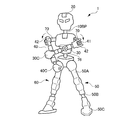
- FIG. 1 is an overall view showing a first appearance of a doll body of the present invention.
- the doll body 1 is formed to resemble a human figure, for example.
- the doll body 1 is made of, for example, a synthetic resin material. *
- the doll body 1 includes a torso 10, and a head 20, a left arm (limb) 30, and a right arm (limb) 40 are attached to the torso 10.
- the torso 10 is composed of a torso body 10A and a waist 10B.
- a left leg (limb) 50 and a right leg (limb) 60 are attached to the waist 10B.
- the left arm portion 30 is configured by sequentially connecting the upper arm portion 30A, the lower arm portion 30B, and the hand portion 30C from the upper shoulder 70 side of the trunk portion 10, and the right arm portion 40 is formed from the shoulder 70 side.
- the upper arm portion 40A, the lower arm portion 40B, and the hand portion 40C are sequentially connected.
- the hand portions 30C and 40C are shown as rods. However, as shown in FIG. 6, for example, hand-shaped members are fitted into the rods as necessary. Yes. *
- the left leg 50 is configured by sequentially connecting the upper leg 50A, the lower leg 50B, and the foot 50C from the waist 10B side, and the right leg 60 is formed from the upper leg 60A from the waist 10B side.
- the lower leg 60B and the foot 60C are sequentially connected.
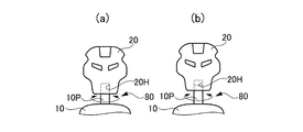
- FIGS. 2A and 2B are diagrams showing a configuration of attachment of the head 20 to the body 10.
- drum 10 it has the space
- the rod body 10P is formed relatively long, and the hole 20H is formed relatively deep. Further, the rod body 10P inserted into the hole 20H can move in the axial direction with a slight friction while being inserted into the hole 20H.
- the head 20 can be arrange
- the rod 10P is provided in the trunk 10 and the hole 20H is provided in the head 20.
- the present invention is not limited to this.
- the hole 20H may be provided in the head 20 with the rod 10P. This is because the same effect can be obtained.
- FIGS. 3A and 3B are diagrams showing a configuration for attaching the waist 10B to the trunk body 10A.
- the interval adjusting portion 81 is formed to protrude from the waist portion 10B, and the rod body 10BP is formed on the trunk portion main body 10A. It is comprised with hole 10AH which inserts.
- the rod body 10BP is formed relatively long, and the hole 10AH is formed relatively deep. Further, the rod body 10BP inserted into the hole 10AH can move in the axial direction with a slight friction while being inserted into the hole 10AH. Thereby, as shown to FIG.
- the waist part 10B can adjust and arrange
- the rod 10BP is provided in the waist 10B, and the hole 10AH is provided in the trunk body 10A.
- the present invention is not limited to this, and there is no hole in the waist 10B.
- 10AH may be provided with the rod body 10BP on the trunk body 10A.
- 4 (a), 4 (b), and 4 (c) are diagrams showing the configuration of the leg portion 50 attached to the waist 10B.
- 4A, 4B, and 4C show the left leg 50, the right leg 60 (see FIG. 1) has the same configuration.
- 4A a shaft 90 (see FIG. 3) that extends to the left and right of the doll body 1 (see FIG. 1) is formed in the waist 10B, and the upper leg into which one end of the shaft 90 is inserted.
- the upper leg 50A can swing in the front-rear direction about the shaft body 90 with respect to the waist 10B. *
- the upper thigh 50A is formed with a length adjusting portion 85, and the length adjusting portion 85 has a rod body 50AP provided on an end surface of one upper thigh divided at that portion, of the other upper thigh. It is configured by being inserted into a hole 50AH formed in the end face.
- the rod body 50AP is formed relatively long, and the hole 50AH is formed relatively deep. Further, the rod body 50AP inserted into the hole 50AH can move in the axial direction with a slight friction while being inserted into the hole 50AH. Thereby, as shown in FIG.4 (b), the upper leg part 50A can adjust the length to the arrow direction in a figure. *
- the upper thigh 50A can be rotated about the rod body 50AP in the direction of the arrow at the location of the length adjusting portion 85.
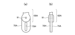
- a joint portion 75 is provided between the upper leg portion 50A and the lower leg portion 50B, and the length adjustment portion 86 is provided in the joint portion 75. That is, at the lower end of the upper leg 50A, as shown in FIGS. 5A and 5B, there is a long hole plate 75A that is pivotally supported by the shaft 91 on the upper leg 50A. The long hole plate 75A is pivotally supported so as to be swingable in the front-rear direction of the doll body 1 with respect to the upper leg part 50A, and is provided with a long hole 75H extending in the longitudinal direction of the leg part 50.
- 5A is a plan view and FIG. 5B is a side view.
- the shaft 92 is formed at the upper end of the crus 50B in a state of being inserted into the long hole 75H of the long hole plate 75A.
- the joint 75 can swing the crus 50B around the shaft 91 or 92 with respect to the crus 50A.
- the joint part 75 comprised in this way also serves as the length adjustment part 86, and as shown in FIG.4 (c), when the shaft body 92 slides along the long hole 75H, it is a long hole board.
- the distance between the upper thigh 50A and the lower thigh 50B that is, the length of the leg 50 can be adjusted in the direction of the arrow in the figure.
- foot portion 50C is attached so as to be rotatable around a shaft body 93 extending to the left and right of the doll body 1 at the lower end of the lower leg portion 50B.
- 6A and 6B are views showing the left arm portion 30 and the right arm portion 40 attached to the shoulder portion 70 of the trunk portion 10.
- 6A is a view of the body 10 viewed from the top (head 20 is omitted)
- FIG. 6B is a view of the body 10 viewed from the front (head 20 is omitted).
- the left arm portion 30 and the right arm portion 40 have the same configuration.
- the right arm 40 will be described. *
- a shoulder portion 70 having a curved portion that is concave on the front side is attached to the upper portion of the body portion 10.
- the shoulder 70 is attached to the body 10 by allowing the body 70 to include a sphere 70A provided at the tip of the shoulder 70 so that the shoulder 70 can swing relative to the body 10. Yes.
- the upper arm 40A is connected to the other end of the shoulder 70 opposite to the body 10.
- a cylindrical body 41 is attached to the other end of the shoulder portion 70 so as to be rotatable around its axis, and a U-shaped body 42 is formed at one end of the upper arm portion 40 so as to sandwich the side surface of the cylindrical body 41.
- Protrusions 43 are respectively formed on the opposing side surfaces of the cylindrical body 41, and these protrusions 43 are inserted into holes 44 formed in the opposing pieces of the U-shaped body 42.
- the upper arm portion 40A can rotate about the axial direction (in the direction of the arrow in the drawing) with respect to the shoulder portion 70.
- the upper arm portion 40 on the right side and the upper arm portion 30 on the left side are shown as being rotated with an angle difference of 90 ° with respect to the shoulder portion 70. *
- the upper arm portion 40A is formed with a length adjusting portion 87, and the length adjusting portion 87 has a rod body 40AP provided on the end surface of one upper arm portion divided at that position on the end surface of the other upper arm portion. It is configured by being inserted into the formed hole 40AH.
- the rod body 40AP is formed relatively long, and the hole 40AH is formed relatively deep. Further, the rod body 40AP inserted into the hole 40AH can move in the axial direction with a slight friction while being inserted into the hole 40AH. Accordingly, the length of the upper arm portion 40A can be adjusted.
- the joint portion 76 between the upper arm portion 40A and the lower arm portion 40B has a U-shaped body 77 formed at the lower end of the upper arm portion 40A and a plate body 78 formed at the upper end of the lower arm portion 40B. It is configured by being connected by a shaft body 79 that penetrates the body 77 and the plate body 78.
- the shape of the shoulder portion 70 is not particularly limited as long as the shoulder portion 70 has a curved portion so that the side portion of the trunk portion 10 can be surrounded when the shoulder portion 70 is rotated forward. .
- it may be a curved shape such as a bow or a shape bent in a dogleg shape.
- the rod 10P that supports the head 20 (see FIG. 2) is disposed in the recess 10Q formed in the body 10, and the doll 1 Are installed in the center of the side surface of the cylindrical body 11 having the support shaft 12 in the left-right direction. As a result, the head 20 can be rotated so as to tilt in the front-rear direction about the support shaft 12.
- the doll body 1 configured as described above includes a length adjusting unit 85 formed on each limb of the left leg 50, the right leg 60, the left arm 30, and the right arm 40. , 86, 87 allow their lengths to be adjusted.
- the distance between the body 10 and the head 20 can be adjusted by the distance adjusting unit 80 formed between the body 10 and the head 20.
- the interval between the body part 10A and the waist part 10B can be adjusted by the distance adjusting part 81 formed between the body part 10A and the waist part 10B.
- FIG. 8 is a block diagram showing Embodiment 2 of the doll body of the present invention. *
- the doll body 1 has the same configuration as the doll body 1 shown in FIG.
- the doll body 1 includes, for example, a length adjusting unit 85 formed on each of the limbs of the left leg 50, the right leg 60, the left arm 30, and the right arm 40, It is assumed that those lengths are maximized by 86 and 87.
- the distance between the body 10 and the head 20 is maximized by the distance adjusting unit 80 formed between the body 10 and the head 20.
- the interval between the body main body 10A and the waist 10B is maximized by the interval adjusting portion 81 formed between the body main body 10A and the waist 10B.
- An alternative head 20 ′ prepared in advance is attached to the head 20 of the doll body 1 so as to cover the head 20.
- the alternative head portion 20 ′ is composed of, for example, two members A and B divided into a front portion and a rear portion, and the head portions 20 and 20 are arranged by addressing these members A and B from the front and the rear of the head portion 20.
- An alternative head 20 ' is attached to the head.
- the members A and B of the alternative head 20 ′ may be configured to be fitted to the head 20, or may be configured to engage the members A and B. In this case, as described above, since the distance between the trunk portion 10 and the head portion 20 is the maximum, the alternative head portion 20 ′ can be attached to the head portion 20 by covering the head portion 20. . *
- a substitute body part 10A 'prepared in advance is attached to the body part 10A of the doll body 1 so as to cover the body part 10A.
- the alternative trunk body 10A ′ is composed of, for example, two members A and B at the front and two members C and D at the rear, and these members A, B, C, and D are arranged from the front and the rear of the trunk body 10A.
- the substitute body 10A ′ is attached to the body 10A by being addressed.
- drum main body 10A ' is a structure fitted to alternative trunk
- the alternative trunk portion main body 10A ′ covers the trunk portion main body 10A.
- it can be attached to the trunk body 10A.
- an alternative waist 10B 'prepared in advance is attached to the waist 10B of the doll body 1 so as to cover the waist 10B.
- the alternative waist portion 10B ′ is composed of, for example, two members A and B divided into a front portion and a rear portion, and the alternative waist portion is attached to the waist portion 10B by applying these members A and B from the front and the rear of the waist portion 10B.
- the members A and B of the alternative waist 10B ' may be configured to be fitted to the waist 10B or may be configured to engage the members A and B.
- the alternative waist portion 10B 'can be attached to the waist portion 10B by covering the waist portion 10B.
- an alternative leg portion 60 ′ prepared in advance is attached to the right leg portion 60 so as to cover the leg portion 60.
- the substitute leg portion 60 ' is constituted by, for example, one member A that addresses the upper leg 60A from the side surface and two members B and C that address the lower leg 60B from the front and rear, respectively. Even if each member A, B, C of alternative leg part 60 'is a structure fitted to leg part 60, respectively, each member A, B, C may be the structure which engages each other. Good.
- the length of the leg portion 60 is the maximum, and the alternative leg portion 60 ′ can be attached to the leg portion 60 according to the length of the leg portion 60. *
- the left leg 50, the left arm 30, and the right arm 40 are shown by omitting the alternative leg and the alternative arm, but the right leg 60. Similarly, it is assumed that the above-described alternative leg portion and alternative arm portion are attached. *
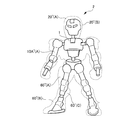
- the doll body 1 configured in this way can form a doll body 2 having a second form which is completely different from the doll body 1 shown in FIG. 1, for example, as shown in FIG. .
- FIG. 10 is a diagram showing the relationship between the doll body 1 and the doll body 2, and shows the doll body 1 through a perspective view of alternative members such as an alternative head and an alternative trunk. *
- the head 20, the trunk 10, the limbs 30, 40, 50, 60 of the doll body 1 are all replaced with the substitute head 20 ′, the substitute trunk 10 ′, the substitute limb 30 ′, 40 ', 50', and 60 'are attached.
- the present invention is not limited to this.
- a new doll body may be configured in such a manner that the alternative head 20 ′ is not attached to the head 20 of the doll body 1. In this case, for example, when the alternative head 20 ′ is not attached, the head 20 can be shortened without increasing the distance from the body 10. *
- the alternative head 20 ', the alternative torso 10', etc. to be attached to the head 20, the torso 10, etc. of the doll body 1 are prepared in various sizes or different forms. Of course, they may be selected and used. *
Landscapes
- Toys (AREA)
Abstract
【課題】 簡単な操作にも拘わらず姿態の異なる別な態様を構成することのできる人形体を提供する。【解決手段】 頭部と、胴部と、関節部を有する複数の肢体と、を有する人形体であって、前記各肢体は、前記肢体の長さを調節する長さ調節部を有する。前記長さ調節部は、前記関節部において、分割された一方の肢体と他方の肢体との分割部に形成され、前記一方の肢体に設けた軸体が他方の肢体の長手方向に延在して形成された長孔に挿入されることによって構成される。また、前記長さ調節部は、分割された一方の肢体と他方の肢体との分割部に形成され、前記一方の肢体の端面に設けた棒体が前記他方の肢体の端面に形成された孔に挿入されることによって構成される。
Description
本発明は人形体に係り、特に、姿態が変化し得る人形体に関する。
人形体からなる玩具において、意外性のある変化に富んだ玩具について種々考案されている。
たとえば、人形体に操作部が設けられ、この操作部による第1の操作で、解除手段が第1の保持手段と他の保持手段の解除を異なる時期に実行し、また、前記操作部による第2の操作で、第1の保持手段と他の保持手段の解除をほぼ同時に実行する機構を備えたものが開示されている(下記特許文献1参照)。
これにより、操作部による操作によって、人形体に異なる変化を起こさせ、意外性のある玩具を得ることができる。
上述した人形体は、上述したように、人形体に、操作部、保持手段、および解除手段等を組み込む必要があり、構成が極めて複雑化するというものである。
しかし、一方において、簡単な操作によって姿態が変化できる人形体を構成できることにより、手軽に人形体の意外性を楽しむことができることが要望される。
本発明は、このような事情に鑑みてなされたものであり、その目的は、簡単な操作にも拘わらず姿態の異なる別な態様を構成できる人形体を提供する。
本発明の人形体は、頭部と、胴部と、関節部を有する複数の肢体と、を有する人形体であって、前記各肢体は、前記肢体の長さを調節する長さ調節部を有する。
本発明の人形体において、前記関節部は、分割された一方の肢体と他方の肢体との分割部に形成され、前記一方の肢体に設けた軸体と、他方の肢体に形成され前記軸体が挿入される孔とで構成され、前記長さ調節部は、前記関節部の前記孔を肢体の長手方向に延在させた長孔として形成することによって構成することが好ましい。また、本発明の人形体において、前記長さ調節部は、分割された一方の肢体と他方の肢体との分割部に形成され、前記一方の肢体の端面に設けた棒体と、前記他方の肢体の端面に形成され前記棒体を挿入可能な開口部とを有することが好ましい。
本発明の人形体において、前記胴部と前記頭部との間隔を調節できる間隔調節部を有し、前記間隔調節部は、前記胴部と前記頭部のうちの一方に設けた棒体と、前記胴部と前記頭部のうちの他方に形成され前記棒体を挿入可能な開口部とを備えることが好ましい。
また、本発明の人形体において、前記胴部は、胴部本体と腰部とで構成され、前記胴部本体と前記腰部との間隔を調節できる間隔調節部を有し、前記間隔調節部は、前記胴部本体と前記腰部のうちの一方に設けた棒体と、前記胴部本体と前記腰部のうちの他方に形成され前記棒体を挿入可能な開口部とを備えることが好ましい。
本発明の人形体において、前記胴部に対して回動可能に取り付けられた肩部材を有し、前記肩部材は、前記肩部材を前方に回動したとき、前記胴部の側面を取り囲むことが可能な曲部を有することが好ましい。
本発明の人形体において、前記長さ調節部によって調節された前記肢体の長さに対応する代替肢体が前記肢体を被って取り付けられていることが好ましい。本発明の人形体において、前記間隔調節部によって調節された前記胴部と前記頭部との間隔に対応する代替胴部および代替頭部の少なくとも一方が前記胴部あるいは前記頭部を被って取り付けられていることが好ましい。本発明の人形体において、前記間隔調節部によって調節された前記胴部本体と前記腰部との間隔に対応する代替胴部本体および代替腰部の少なくとも一方が前記胴部本体あるいは前記腰部を被って取り付けられていることが好ましい。
このように構成した人形体によれば、簡単な操作にも拘わらず姿態の異なる別な態様を構成することができる。
以下、添付図面を参照して、本発明を実施するための形態(以下、実施形態)について詳細に説明する。なお、実施形態の説明の全体を通して同じ要素には同じ番号を付している。(実施形態1) 図1は、本発明の人形体の第1姿態を示す全体図である。人形体1は、たとえば人間の姿に似せて形成されている。人形体1は、たとえば合成樹脂の材料から構成されている。
図1に示すように、人形体1は胴部10を備え、この胴部10には頭部20、左側の腕部(肢体)30、右側の腕部(肢体)40が取り付けられている。また、胴部10は、胴部本体10Aと腰部10Bとで構成され、腰部10Bには、左側の脚部(肢体)50、右側の脚部(肢体)60が取り付けられている。
左側の腕部30は、胴部10の上部の肩70側から、上腕部30A、下腕部30B、および手部30Cが順次連結されて構成され、右側の腕部40は、肩70側から、上腕部40A、下腕部40B、および手部40Cが順次連結されて構成されている。
なお、図1では、前記手部30C、40Cは棒体として示しているが、たとえば図6に示すように、必要に応じて該棒体に手の形をした部材が嵌め込まれるようになっている。
左側の脚部50は、腰部10B側から、上腿部50A、下腿部50B、および足部50Cが順次連結されて構成され、右側の脚部60は、腰部10B側から、上腿部60A、下腿部60B、および足部60Cが順次連結されて構成されている。
図2(a)、(b)は、頭部20の胴部10に対する取り付けの構成を示した図である。頭部20と胴部10の間には間隔調節部80を有し、この間隔調節部80は、胴部10から突出して形成された棒体10Pと、頭部20に形成され該棒体10Pを挿入させる孔20Hとで構成されている。棒体10Pは比較的長く形成され、孔20Hは比較的深く形成されている。また、孔20Hに挿入される棒体10Pは、該孔20Hに挿入された状態で若干の摩擦を有して軸方向に移動できるようになっている。これにより、図2(a)、(b)に示すように、頭部20は、胴部10に対してそれらの間隔を調整して配置させることができるようになっている。また、頭部20は胴体10に対して棒体10Pを中心として図中矢印方向に回動できるようになっている。
なお、図2(a)(b)では、胴部10に棒体10Pを、頭部20に孔20Hを設けるようにしたものであるが、これに限定されることはなく、胴部10に孔20Hを、頭部20に棒体10Pを設けるにようにしてもよい。同様の効果が得られるからである。
図3(a)、(b)は、腰部10Bの胴部本体10Aに対する取り付けの構成を示した図である。胴部本体10Aと腰部10Bの間には間隔調節部81を有し、この間隔調節部81は、腰部10Bから突出して形成された棒体10BPと、胴部本体10Aに形成され該棒体10BPを挿入させる孔10AHとで構成されている。棒体10BPは比較的長く形成され、孔10AHは比較的深く形成されている。また、孔10AHに挿入される棒体10BPは、該孔10AHに挿入された状態で若干の摩擦を有して軸方向に移動できるようになっている。これにより、図3(a)、(b)に示すように、腰部10Bは、胴部本体10Aに対してそれらの間隔を調整して配置させることができるようになっている。また、腰部10Bは胴部本体10Aに対して棒体10BPを中心として図中矢印方向に回動できるようになっている。
なお、図3(a)(b)では、腰部10Bに棒体10BPを、胴部本体10Aに孔10AHを設けるようにしたものであるが、これに限定されることはなく、腰部10Bに孔10AHを、胴部本体10Aに棒体10BPを設けるにようにしてもよい。
図4(a)、(b)、(c)は、腰部10Bに取り付けた脚部50の構成を示した図である。なお、図4(a)、(b)、(c)では、左側の脚部50を示しているが、右側の脚部60(図1参照)においても同様の構成となっている。図4(a)において、腰部10Bには、人形体1(図1参照)の左右に延在する軸体90(図3参照)が形成され、この軸体90の一端が挿入される上腿部50Aを有する。この上腿部50Aは、腰部10Bに対して軸体90を中心に前後方向に揺動できるようなっている。
また、上腿部50Aは、長さ調節部85が形成され、長さ調節部85は、その箇所で分割された一方の上腿部の端面に設けた棒体50APが他方の上腿部の端面に形成された孔50AHに挿入されることによって構成されている。棒体50APは比較的長く形成され、孔50AHは比較的深く形成されている。また、孔50AHに挿入される棒体50APは、該孔50AHに挿入された状態で若干の摩擦を有して軸方向に移動できるようになっている。これにより、上腿部50Aは、図4(b)に示すように、その長さを図中矢印方向に調節できるようになっている。
なお、上腿部50Aは、図4(a)に示すように、長さ調節部85の箇所において、棒体50APを中心として図中矢印方向に回動できるようになっている。
また、上腿部50Aと下腿部50Bとの間に関節部75を有し、この関節部75において、長さ調節部86を備えた構成となっている。すなわち、上腿部50Aの下端部には、図5(a)、(b)に示すように、上腿部50Aに軸体91によって軸支された長孔板75Aを有する。長孔板75Aは、上腿部50Aに対して人形体1の前後方向に揺動できるように軸支され、脚部50の長手方向に延在する長孔75Hが設けられている。なお、図5(a)は平面図を、図5(b)は側面図である。また、図4(a)に戻り、下腿部50Bの上端部には、軸体92が長孔板75Aの長孔75Hに挿入された状態で形成されている。これにより、関節部75は、下腿部50Bが上腿部50Aに対して軸体91あるいは92を中心として揺動できるようになっている。そして、このように構成された関節部75は、長さ調節部86を兼ね、図4(c)に示すように、軸体92が長孔75Hに沿って摺動することにより、長孔板75Aの長孔75Hの長さに応じて、図中矢印方向に上腿部50Aと下腿部50Bの間隔を、すなわち、脚部50の長さを調節できるようになっている。
また、足部50Cは下腿部50Bの下端において人形体1の左右に延在する軸体93を中心に回動できるようにして取り付けられている。
図6(a)、(b)は、胴部10の肩部70に取り付けられた左側の腕部30および右側の腕部40を示した図である。図6(a)は、胴部10を上面から観た図(頭部20は省略)、図6(b)は、胴部10を正面から観た図(頭部20は省略)である。
図6(a)、(b)において、左側の腕部30および右側の腕部40はいずれも同様の構成となっている。ここでは、たとえば右側の腕部40の説明をする。
まず、胴部10の上部には前方側に凹となる湾曲部を有する肩部70が取り付けられている。肩部
70の胴部10への取り付けは、肩部70の先端に設けられた球体70Aが胴体10によって内包されることにより、肩部70の胴部10に対する揺動的な動きを可能にしている。
70の胴部10への取り付けは、肩部70の先端に設けられた球体70Aが胴体10によって内包されることにより、肩部70の胴部10に対する揺動的な動きを可能にしている。
肩部70の胴体10と反対側の他端には上腕部40Aが連結されている。肩部70の他端には円柱体41がその軸周りに回転できるように取り付けられ、上腕部40の一端には円柱体41の側面を挟持するようにコ字状体42が形成されている。円柱体41の対向する側面にはそれぞれ突起43が形成され、これら突起43はコ字状体42の対向する各片に形成された孔44に挿入されている。これにより、上腕部40Aは肩部70に対して軸方向の周り(図中矢印方向)に回転できるようになっている。なお、図中右側の上腕部40と左側の上腕部30は、それぞれ、肩部70に対して90°の角度差を有して回転されている状態を示している。
また、上腕部40Aには、長さ調節部87が形成され、長さ調節部87は、その箇所で分割された一方の上腕部の端面に設けた棒体40APが他方の上腕部の端面に形成された孔40AHに挿入されることによって構成されている。棒体40APは比較的長く形成され、孔40AHは比較的深く形成されている。また、孔40AHに挿入される棒体40APは、該孔40AHに挿入された状態で若干の摩擦を有して軸方向に移動できるようになっている。これにより、上腕部40Aは、その長さを調節できるようになっている。
上腕部40Aと下腕部40Bの間の関節部76は、上腕部40Aの下端に形成されたコ字状体77に下腕部40Bの上端に形成された板体78が、該コ字状体77および板体78を貫通する軸体79によって連結されることによって構成されている。
このように構成された左側の腕部30および右側の腕部40は、それらが取り付けられる肩部70において、人形体1の前方側に凹となる湾曲部を有するように構成したことから、胴部10の前方に近接させて配置させることが容易になる。なお、肩部70の形状は、肩部70を前方に回動させたときに胴部10の側部を取り囲むことが可能なように曲部を有する形状であれば特に限定されるものではない。例えば、弓形のような湾曲した形状や、くの字状に屈曲した形状であってもよい。このような形状を有することにより、たとえば、図7に示すように、左側の腕部30および右側の腕部40を互いに腕組みさせるようにして配置させることができるようになる。
なお、図6(a)、(b)から明らかなように、頭部20(図2参照)を支持する棒体10Pは、胴部10に形成された凹部10Q内に配置され、人形体1の左右方向に支軸12を有する円柱体11の側面の中央に植設されている。これにより、頭部20は支軸12を中心にして前後方向に傾くように回動させることができるようになる。
このように構成された人形体1は、左側の脚部50、右側の脚部60、左側の腕部30、右側の腕部40の各肢体において、それら肢体に形成された長さ調節部85、86、87によって、それらの長さを調節することができるようになる。また、胴部10と頭部20の間に形成した間隔調節部80によって、胴部10と頭部20の間隔を調節することができるようになる。さらに、胴部本体10Aと腰部10Bの間に形成した間隔調節部81によって、胴部本体10Aと腰部10Bの間隔を調節することができるようになる。
このため、人形体1において、各肢体の長さ、胴部10と頭部20の間隔、胴部本体10Aと腰部10Bの間隔を変えることができ、人形体1の全体の姿態の変化を楽しむことができる効果を奏するようになる。(実施形態2) 図8は、本発明の人形体の実施形態2を示す構成図である。
図8において、人形体1は、図1に示した人形体1と同様の構成となっている。この場合、人形体1は、たとえば、左側の脚部50、右側の脚部60、左側の腕部30、右側の腕部40の各肢体において、それら肢体に形成された長さ調節部85、86、87によって、それらの長さが最大となっているとする。そして、胴部10と頭部20の間に形成した間隔調節部80によって、たとえば、胴部10と頭部20の間隔が最大となっているとする。さらに、胴部本体10Aと腰部10Bの間に形成した間隔調節部81によって、たとえば、胴部本体10Aと腰部10Bの間隔が最大となっているとする。
そして、人形体1の頭部20には、予め用意された代替頭部20’が該頭部20を被って取り付けられるようになっている。代替頭部20’は、たとえば、前方と後方とに分割された2つの部材A、Bから構成され、これら部材A、Bを頭部20の前方および後方から宛がうことによって該頭部20に代替頭部20’が取り付けられるようになっている。なお、代替頭部20’の各部材A、Bは、それぞれ、頭部20に嵌合される構成であっても、各部材A、B同士が係合するような構成であってもよい。この場合、上述したように、胴部10と頭部20の間隔が最大となっていることから、代替頭部20’は頭部20を被って該頭部20に取り付けることができるようになる。
同様に、人形体1の胴部本体10Aには、予め用意された代替胴部本体10A’が該胴部本体10Aを被って取り付けられるようになっている。代替胴部本体10A’は、たとえば、前方で2つの部材A、B、後方で2つの部材C、Dで構成され、これら部材A、B、C、Dを胴部本体10Aの前方および後方から宛がうことによって該胴部本体10Aに代替胴部本体10A’が取り付けられるようになっている。なお、代替胴部本体10A’の各部材A、B、C、Dは、それぞれ、代替胴部本体10A’に嵌合される構成であっても、各部材同士A、B、C、Dが係合するような構成であってもよい。この場合、上述したように、胴部10と頭部20の間隔、また胴部本体10Aと腰部10Bの間隔が最大となっていることから、代替胴部本体10A’は胴部本体10Aを被って該胴部本体10Aに取り付けることができるようになる。
同様に、人形体1の腰部10Bには、予め用意された代替腰部10B’が該腰部10Bを被って取り付けられるようになっている。代替腰部10B’は、たとえば、前方と後方とに分割された2つの部材A、Bから構成され、これら部材A、Bを腰部10Bの前方および後方から宛がうことによって該腰部10Bに代替腰部10B’が取り付けられるようになっている。代替腰部10B’の各部材A、Bは、それぞれ、腰部10Bに嵌合される構成であっても、各部材A、B同士が係合するような構成であってもよい。この場合、上述したように、胴部本体10Aと腰部10Bの間隔が最大となっていることから、代替腰部10B’は腰部10Bを被って該腰部10Bに取り付けることができるようになる。
さらに、たとえば、右側の脚部60には、予め用意された代替脚部60’が該脚部60を被って取り付けられるようになっている。代替脚部60’は、たとえば、上腿部60Aを側面から宛がう1つの部材A、下腿部60Bを前方および後方からそれぞれ宛がう2つの部材B、Cによって構成されている。代替脚部60’の各部材A、B、Cは、それぞれ、脚部60に嵌合される構成であっても、各部材A、B、C同士が係合するような構成であってもよい。この場合、上述したように、脚部60の長さが最大となっており、代替脚部60’は該脚部60の長さに応じて該脚部60に取り付けることができるようになる。
なお、図8では、左側の脚部50、左側の腕部30、および右側の腕部40におけるそれぞれの代替脚部、代替腕部を省略して示したものであるが、右側の脚部60と同様に、上述した代替脚部、および代替腕部が取り付けられているものとする。
このように構成された人形体1は、たとえば図9に示すように、図1に示した人形体1と比べて全く姿態の異なる第2姿態の人形体2を構成することができるようになる。図10は、人形体1と人形体2の関係を示した図で、代替頭部、代替胴部等の代替部材を透視させて人形体1を示した図である。
(実施形態3) 実施形態2では、人形体1の頭部20、胴部10、肢体30、40、50、60の全てに代替頭部20’、代替胴部10’、代替肢体30’、40’、50’、60’を取り付けるように構成したものである。しかし、これに限定されることはなく、たとえば人形体1の頭部20には代替頭部20’を取り付けない等の姿態で新たな人形体を構成するようにしてもよい。この場合、たとえば、代替頭部20’を取り付けない場合において、頭部20は胴部10との間隔を長くすることなく短くした状態とすることもできる。
(実施形態4) また、人形体1の頭部20、胴部10等に取り付ける代替頭部20’、代替胴部10’等は、種々の大きさあるいは形態の異なるものを用意しておき、それらを選択して用いるようにしてもよいことはもちろんである。
(実施形態5) 上述した実施形態では、いずれも人間の姿に似せた人形体について説明したものである。しかし、これに限定されることはなく、たとえば動物等の姿に似せた人形体にも適用できることはいうまでもない。
以上、実施形態を用いて本発明を説明したが、本発明の技術的範囲は上記実施形態に記載の範囲には限定されないことは言うまでもない。上記実施形態に、多様な変更または改良を加えることが可能であることが当業者に明らかである。また、その様な変更または改良を加えた形態も本発明の技術的範囲に含まれ得ることが、特許請求の範囲の記載から明らかである。
1、2……人形体、10……胴部、10A……胴部本体、10A’……代替胴部本体、10AH……孔、10B……腰部、10B’……代替要部、10BP……棒体、10P……棒体、10Q……凹部、11……円柱体、12……支軸、20……頭部、20H……孔、30……左側の腕部(肢体)、30A……上腕部、30B……下腕部、30C……手部、40……右側の腕部(肢体)、40A……上腕部、40B……下腕部、40C……手部、40AP……棒体、40AH……孔、41……円柱体、42……コ字状体、43……突起、44……孔、50……左側の脚部(肢体)、50A……上腿部、50B……下腿部、50C……足部、60……右側の脚部(肢体)、60A……上腿部、60B……下腿部、60C……足部、70……肩、70A……球体、75……関節部、75A……長孔板、75H……長孔、76……関節部、77……コ字状体、78……板体、79……軸体、80、81……間隔調節部、85、86、87……長さ調節部、90、91、92、93……軸体。
Claims (9)
- 頭部と、胴部と、関節部を有する複数の肢体と、を有する人形体であって、 前記各肢体は、前記肢体の長さを調節する長さ調節部を有する人形体。
- 請求項1において、 前記関節部は、分割された一方の肢体と他方の肢体との分割部に形成され、前記一方の肢体に設けた軸体と、他方の肢体に形成され前記軸体が挿入される孔とで構成され、 前記長さ調節部は、前記関節部の前記孔を肢体の長手方向に延在させた長孔として形成することによって構成する人形体。
- 請求項1において、 前記長さ調節部は、分割された一方の肢体と他方の肢体との分割部に形成され、 前記一方の肢体の端面に設けた棒体と、前記他方の肢体の端面に形成され前記棒体を挿入可能な開口部とを有する人形体。
- 請求項1において、 前記胴部と前記頭部との間隔を調節できる間隔調節部を有し、 前記間隔調節部は、前記胴部と前記頭部のうちの一方に設けた棒体と、前記胴部と前記頭部のうちの他方に形成され前記棒体を挿入可能な開口部とを備える人形体。
- 請求項1において、 前記胴部は、胴部本体と腰部とで構成され、 前記胴部本体と前記腰部との間隔を調節できる間隔調節部を有し、 前記間隔調節部は、前記胴部本体と前記腰部のうちの一方に設けた棒体と、前記胴部本体
と前記腰部のうちの他方に形成され前記棒体を挿入可能な開口部とを備える人形体。 - 請求項1において、 前記胴部に対して回動可能に取り付けられた肩部材を有し、 前記肩部材は、前記肩部材を前方に回動したとき、前記胴部の側面を取り囲むことが可能な曲部を有する人形体。
- 請求項1において、 前記長さ調節部によって調節された前記肢体の長さに対応する代替肢体が前記肢体を被って取り付けられている人形体。
- 請求項4において、 前記間隔調節部によって調節された前記胴部と前記頭部との間隔に対応する代替胴部および代替頭部の少なくとも一方が前記胴部あるいは前記頭部を被って取り付けられている人形体。
- 請求項5において、 前記間隔調節部によって調節された前記胴部本体と前記腰部との間隔に対応する代替胴部本体および代替腰部の少なくとも一方が前記胴部本体あるいは前記腰部を被って取り付けられている人形体。
Priority Applications (1)
| Application Number | Priority Date | Filing Date | Title |
|---|---|---|---|
| US14/764,892 US20150375127A1 (en) | 2013-02-22 | 2013-12-17 | Doll figure |
Applications Claiming Priority (2)
| Application Number | Priority Date | Filing Date | Title |
|---|---|---|---|
| JP2013-033848 | 2013-02-22 | ||
| JP2013033848A JP5571810B1 (ja) | 2013-02-22 | 2013-02-22 | 人形体 |
Publications (1)
| Publication Number | Publication Date |
|---|---|
| WO2014129065A1 true WO2014129065A1 (ja) | 2014-08-28 |
Family
ID=51390876
Family Applications (1)
| Application Number | Title | Priority Date | Filing Date |
|---|---|---|---|
| PCT/JP2013/083757 Ceased WO2014129065A1 (ja) | 2013-02-22 | 2013-12-17 | 人形体 |
Country Status (3)
| Country | Link |
|---|---|
| US (1) | US20150375127A1 (ja) |
| JP (1) | JP5571810B1 (ja) |
| WO (1) | WO2014129065A1 (ja) |
Cited By (1)
| Publication number | Priority date | Publication date | Assignee | Title |
|---|---|---|---|---|
| JP7366305B1 (ja) | 2023-05-09 | 2023-10-20 | 株式会社バンダイ | 模型玩具、及び模型玩具の構造体 |
Families Citing this family (11)
| Publication number | Priority date | Publication date | Assignee | Title |
|---|---|---|---|---|
| JP6796110B2 (ja) * | 2018-06-29 | 2020-12-02 | 株式会社バンダイ | 腕構造及び人型玩具 |
| US10881977B1 (en) * | 2019-09-11 | 2021-01-05 | Evolutive Labs Co., Ltd. | Leg assembly of a toy figure |
| JP7062736B2 (ja) * | 2020-09-30 | 2022-05-06 | 株式会社バンダイ | 人形体の関節構造 |
| US20230390656A1 (en) * | 2022-06-03 | 2023-12-07 | Great Eastern Entertainment Co | Plush Toy with Internal Skeleton and Rotatable Head |
| US20230390659A1 (en) * | 2022-06-03 | 2023-12-07 | Great Eastern Entertainment Co. | Plush Toy with Internal Skeleton and Rotatable Head |
| US11944915B2 (en) * | 2022-06-03 | 2024-04-02 | Great Eastern Entertainment Co. | Plush toy with internal skeleton and rotatable head |
| US12246264B2 (en) * | 2022-06-03 | 2025-03-11 | Great Eastern Entertainment, Co | Plush toy with removable wig |
| US12594509B2 (en) * | 2023-08-19 | 2026-04-07 | Farco ToyCo LLC | Interconnecting methods and systems for posable bendable building block toys |
| USD1046017S1 (en) * | 2024-04-15 | 2024-10-08 | Dong Xu | Element for poseable action figure |
| US12201915B1 (en) | 2024-04-22 | 2025-01-21 | Mattel, Inc. | Connector for a toy figure |
| JP7794893B1 (ja) * | 2024-06-19 | 2026-01-06 | 株式会社バンダイ | 人形体 |
Citations (8)
| Publication number | Priority date | Publication date | Assignee | Title |
|---|---|---|---|---|
| JPS6145993U (ja) * | 1984-08-28 | 1986-03-27 | 株式会社 タカラ | ロボツト玩具等の関節構造 |
| JPH02159291A (ja) * | 1988-12-14 | 1990-06-19 | Takara Co Ltd | 人形玩具 |
| JPH076950Y2 (ja) * | 1988-05-16 | 1995-02-22 | 株式会社タカラ | 戦闘人形 |
| JP2000140449A (ja) * | 1998-11-05 | 2000-05-23 | Takara Co Ltd | 人形玩具の腕部構造 |
| JP2002227829A (ja) * | 2001-01-31 | 2002-08-14 | Mega House:Kk | 関節装置及び人形体 |
| JP3863501B2 (ja) * | 2003-05-19 | 2006-12-27 | 株式会社コナミデジタルエンタテインメント | 形態変形玩具 |
| JP3136840U (ja) * | 2007-08-08 | 2007-11-08 | 株式会社海洋堂 | 可動玩具 |
| JP4500220B2 (ja) * | 2005-06-17 | 2010-07-14 | 株式会社オビツ製作所 | 人形の球状関節 |
Family Cites Families (2)
| Publication number | Priority date | Publication date | Assignee | Title |
|---|---|---|---|---|
| US2623329A (en) * | 1950-03-31 | 1952-12-30 | Leva Anthony Di | Extensible doll |
| ITRM20000426A1 (it) * | 2000-07-31 | 2002-01-31 | Claudio Rosa | Dispositivo per ottenere l'allungamento degli arti e/o di altre partidel corpo di un pupazzo, quale ad esempio un bambolotto ed altri gioca |
-
2013
- 2013-02-22 JP JP2013033848A patent/JP5571810B1/ja active Active
- 2013-12-17 WO PCT/JP2013/083757 patent/WO2014129065A1/ja not_active Ceased
- 2013-12-17 US US14/764,892 patent/US20150375127A1/en not_active Abandoned
Patent Citations (8)
| Publication number | Priority date | Publication date | Assignee | Title |
|---|---|---|---|---|
| JPS6145993U (ja) * | 1984-08-28 | 1986-03-27 | 株式会社 タカラ | ロボツト玩具等の関節構造 |
| JPH076950Y2 (ja) * | 1988-05-16 | 1995-02-22 | 株式会社タカラ | 戦闘人形 |
| JPH02159291A (ja) * | 1988-12-14 | 1990-06-19 | Takara Co Ltd | 人形玩具 |
| JP2000140449A (ja) * | 1998-11-05 | 2000-05-23 | Takara Co Ltd | 人形玩具の腕部構造 |
| JP2002227829A (ja) * | 2001-01-31 | 2002-08-14 | Mega House:Kk | 関節装置及び人形体 |
| JP3863501B2 (ja) * | 2003-05-19 | 2006-12-27 | 株式会社コナミデジタルエンタテインメント | 形態変形玩具 |
| JP4500220B2 (ja) * | 2005-06-17 | 2010-07-14 | 株式会社オビツ製作所 | 人形の球状関節 |
| JP3136840U (ja) * | 2007-08-08 | 2007-11-08 | 株式会社海洋堂 | 可動玩具 |
Cited By (3)
| Publication number | Priority date | Publication date | Assignee | Title |
|---|---|---|---|---|
| JP7366305B1 (ja) | 2023-05-09 | 2023-10-20 | 株式会社バンダイ | 模型玩具、及び模型玩具の構造体 |
| WO2024232176A1 (ja) * | 2023-05-09 | 2024-11-14 | 株式会社バンダイ | 模型玩具、及び構造体 |
| JP2024162123A (ja) * | 2023-05-09 | 2024-11-21 | 株式会社バンダイ | 模型玩具、及び模型玩具の構造体 |
Also Published As
| Publication number | Publication date |
|---|---|
| JP5571810B1 (ja) | 2014-08-13 |
| JP2014161453A (ja) | 2014-09-08 |
| US20150375127A1 (en) | 2015-12-31 |
Similar Documents
| Publication | Publication Date | Title |
|---|---|---|
| JP5571810B1 (ja) | 人形体 | |
| JP6059786B1 (ja) | 人形体の肩関節構造 | |
| JP4268197B2 (ja) | 人形の関節 | |
| JP2014168723A (ja) | 人形体 | |
| JP6030615B2 (ja) | 人形玩具の肩関節構造及び人形玩具 | |
| JP3863501B2 (ja) | 形態変形玩具 | |
| JP5650266B2 (ja) | 形態変化玩具 | |
| JP2024009154A (ja) | 人形体 | |
| JP2019030684A (ja) | 人形玩具の肩関節構造及び人形玩具 | |
| JP5327672B2 (ja) | 視線調整可能な義眼及び該義眼を固定した人形頭部 | |
| JP7105105B2 (ja) | 人形の関節構造及び人形 | |
| JP6562894B2 (ja) | 人形体の肩関節構造 | |
| US20070281582A1 (en) | Doll Joint | |
| JP6975211B2 (ja) | 玩具 | |
| JP2019063339A (ja) | 人形の関節構造 | |
| JP7402852B2 (ja) | 構造体 | |
| JP7360508B1 (ja) | 玩具の可動構造 | |
| JP6411429B2 (ja) | 人形玩具の肩関節構造及び人形玩具 | |
| WO2023243283A1 (ja) | 玩具の射出機構 | |
| JP2024162962A (ja) | 模型玩具、及び構造体 | |
| WO2022130907A1 (ja) | 人形体、股関節部、及び回動機構 | |
| JP7137175B2 (ja) | 人形の関節構造 | |
| JP6951727B2 (ja) | 人形用の関節構造 | |
| JP2022113812A (ja) | 玩具 | |
| JP2021041218A (ja) | 人形玩具の肩関節構造及び人形玩具 |
Legal Events
| Date | Code | Title | Description |
|---|---|---|---|
| 121 | Ep: the epo has been informed by wipo that ep was designated in this application |
Ref document number: 13875942 Country of ref document: EP Kind code of ref document: A1 |
|
| WWE | Wipo information: entry into national phase |
Ref document number: 14764892 Country of ref document: US |
|
| NENP | Non-entry into the national phase |
Ref country code: DE |
|
| 122 | Ep: pct application non-entry in european phase |
Ref document number: 13875942 Country of ref document: EP Kind code of ref document: A1 |