WO2022130907A1 - 人形体、股関節部、及び回動機構 - Google Patents
人形体、股関節部、及び回動機構 Download PDFInfo
- Publication number
- WO2022130907A1 WO2022130907A1 PCT/JP2021/042734 JP2021042734W WO2022130907A1 WO 2022130907 A1 WO2022130907 A1 WO 2022130907A1 JP 2021042734 W JP2021042734 W JP 2021042734W WO 2022130907 A1 WO2022130907 A1 WO 2022130907A1
- Authority
- WO
- WIPO (PCT)
- Prior art keywords
- hip joint
- doll body
- connecting member
- leg
- doll
- Prior art date
Links
- 210000004394 hip joint Anatomy 0.000 title claims abstract description 113
- 210000002414 leg Anatomy 0.000 claims abstract description 75
- 210000001624 hip Anatomy 0.000 claims abstract description 26
- 210000000689 upper leg Anatomy 0.000 description 9
- 210000002683 foot Anatomy 0.000 description 5
- 210000003127 knee Anatomy 0.000 description 5
- 210000001503 joint Anatomy 0.000 description 4
- 241000282412 Homo Species 0.000 description 3
- 238000005034 decoration Methods 0.000 description 3
- 241001465754 Metazoa Species 0.000 description 2
- 210000003423 ankle Anatomy 0.000 description 2
- 238000005452 bending Methods 0.000 description 2
- 230000004048 modification Effects 0.000 description 2
- 238000012986 modification Methods 0.000 description 2
- 241000086550 Dinosauria Species 0.000 description 1
- 241000238631 Hexapoda Species 0.000 description 1
- 230000000386 athletic effect Effects 0.000 description 1
- 210000001217 buttock Anatomy 0.000 description 1
- 239000000470 constituent Substances 0.000 description 1
- 210000003414 extremity Anatomy 0.000 description 1
- 230000009191 jumping Effects 0.000 description 1
- 210000004705 lumbosacral region Anatomy 0.000 description 1
- 238000004519 manufacturing process Methods 0.000 description 1
- 238000003825 pressing Methods 0.000 description 1
Images


Classifications
-
- A—HUMAN NECESSITIES
- A63—SPORTS; GAMES; AMUSEMENTS
- A63H—TOYS, e.g. TOPS, DOLLS, HOOPS OR BUILDING BLOCKS
- A63H3/00—Dolls
- A63H3/36—Details; Accessories
-
- A—HUMAN NECESSITIES
- A63—SPORTS; GAMES; AMUSEMENTS
- A63H—TOYS, e.g. TOPS, DOLLS, HOOPS OR BUILDING BLOCKS
- A63H3/00—Dolls
- A63H3/36—Details; Accessories
- A63H3/46—Connections for limbs
-
- A—HUMAN NECESSITIES
- A63—SPORTS; GAMES; AMUSEMENTS
- A63H—TOYS, e.g. TOPS, DOLLS, HOOPS OR BUILDING BLOCKS
- A63H3/00—Dolls
- A63H3/36—Details; Accessories
- A63H3/48—Mounting of parts within dolls, e.g. automatic eyes or parts for animation
Definitions
- the present invention relates to a doll body, a hip joint portion, and a rotation mechanism.
- Doll toys include various joints and moving parts in order to realize movements and poses similar to those of humans and animals.
- providing the same number of joints and the like as humans on a doll toy requires a large number of members, and even an elaborate doll toy has a limited number and is difficult to realize. Therefore, in order to realize the above-mentioned movements and poses, it is important to expand the range of motion of the joints and the parts connected to them while constituting them with fewer joints and members. By expanding the range of motion, it is possible to perform more flexible movements and various poses. It was
- Patent Document 1 proposes a doll body in which a connecting member connected to a hip joint rotates between an open position and a closed position, and a leg is connected to the tip of the connecting member. In this doll body, the movements of open legs and closed legs can be realized.
- the connecting member can rotate between the open position and the closed position, its operation direction is unidirectional. In order to realize natural movements like human limbs, it is desirable that they can rotate in various directions.
- the hip joint inside the waist like a human it is possible to realize a natural leg connected to the hip joint, but the operating space thereof is limited. That is, it is required to rotate the legs more freely in the space limited by the relationship with other members such as the waist and the skirt. It was
- the present invention provides a mechanism for expanding the range of motion of the hip joint, for example, in a doll body, and realizing more flexible movements and various poses.
- the present invention is, for example, a doll body, a hip joint portion to which the upper body portion is connected, and a hip joint portion provided at the rear portion of the hip joint portion and corresponding to the left and right legs, respectively.
- One end of the sphere is rotatably connected to each connecting member whose rotatably supported hip joint and the other end of each connecting member are rotatably connected to both sides of the lumbar joint. It is characterized by having each leg. It was
- the present invention is, for example, a rotation mechanism of the hip joint portion and the leg portion of the doll body, and each hip joint corresponding to the left and right leg portions provided at the rear portion of the hip joint portion to which the upper body portion is connected.
- the first rotating portion in which one spherical end of each connecting member is pivotally supported, and the other end of each connecting member can be rotated near both sides of the lumbar joint. It is characterized in that it is provided with a second rotating portion for connecting the respective legs.
- the range of motion of the hip joint can be widened, and more flexible movements and various poses can be realized.
- FIG. 1 shows the front view of the appearance of the doll body 100. It was
- the doll body (doll toy) 100 includes a head portion 101, a body portion 102, an arm portion 103, a waist portion 104, and a leg portion 105 (105a, 105b).
- the head 101 is connected to the body portion 102.
- An arm portion 103 including a right arm and a left arm is further connected to the body portion 102, and a waist portion 104 is connected to the lower part.
- a leg 105 including a right foot 105a and a left foot 105b is connected to the lumbar portion 104.
- the upper body including the head 101, the torso 102, and the arms 103 will be referred to as an upper body.
- the lumbar portion 104 is located in the region shown by the dotted line in FIG.
- the waist portion 104 may be provided with decorations such as clothes of the doll body 100 on the outside. These decorations may be provided integrally with the lumbar portion 104. It was
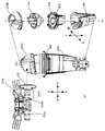
- FIG. 2A shows a perspective view of the lower body of the upper body to which only the left foot is connected
- FIG. 2B shows an exploded perspective view of FIG. 2A
- 2 (a) and 2 (b) are both perspective views seen from below of the doll body 100, showing a state in which the inside of the lumbar region 104 can be seen from the upper body with the right foot removed.
- the up / down, left / right, and front / back arrows indicate the orientation of the doll in the figure, and the same applies to the other drawings. It was
- the lumbar portion 104 includes a lumbar portion basic member 104a and a lumbar portion decorative member 104b.
- the detailed configuration of the waist portion 104 will be described later with reference to FIGS. 4 and 5.
- the leg portion 105 is composed of a connecting portion 202b rotatably connected to the connecting member 201 (201a, 201b) and a leg portion main body 203b. The detailed configuration of the leg portion 105 will be described later with reference to FIG.
- the leg portion 105 is rotatably connected to a connecting member 201 connected to each of the hip joint portions corresponding to the left and right leg portions a and 105b of the waist portion 104 in the vicinity of the side portion of the hip joint portion. It was
- FIG. 3A shows a state in which the leg portion 105b is connected to the lumbar portion 104
- FIG. 3B is an exploded view of the leg portion 105b.
- 3 (a) and 3 (b) both show the configuration from the base of the leg 105b corresponding to the left foot to the knee portion.
- Other parts are omitted for the sake of brevity. It was
- one end of the connecting member 201b is rotatably connected to the hip joint portion, and the other end 502b is connected to the leg portion 105b.
- the other end 502b connected to the leg portion 105b is formed in a cylindrical shape.
- the connecting portion 202b of the leg portion 105b is formed with a fitting portion 310 for receiving a cylindrical member which is the other end 502b of the connecting member 201b. Therefore, the leg portion 105b connected to the other end 502b can be rotated around the cylindrical shape.
- the rotation mechanism is an example of the second rotating portion, and the leg portion 105b can be rotated in the front-rear direction 302 of the doll body 100. It was
- the leg body 203b of the leg 105b is configured such that its thigh portion is rotatable in the direction of the arrow 303 about the axial direction of the leg 105b. This will be described in detail with reference to FIG. 3 (b).
- the leg portion 105b includes a connecting portion 202b and a leg portion main body 203b.
- the leg body 203b includes a mounting member 305, a rotating member 306, and a thigh 307.
- the mounting member 305 is mounted on the connecting portion 202b.
- the mounting member 305 is fitted and fixed to the connecting portion 202b.
- the lower portion of the mounting member 305 is composed of a cylindrical member.
- the rotating member 306 is fitted so as to be rotatable (rotatably) in the direction of the arrow 308. Further, the thigh portion 307 is attached and fixed to the rotating member 306. Although not shown, the configuration below the knee is connected to the lower part of the thigh 307. Therefore, the constituent members below the thigh portion 307 follow the rotation by the lower portion of the mounting member 305 and the rotating member 306.
- the rotation mechanism is an example of the third rotating portion, and the thigh and below of the leg portion 105 can be rotated in the directions of arrows 303 and 308 about the axial direction of the leg portion. Even below the knee (not shown), it is desirable that the knee and ankle are rotatably configured at least at the positions of the knee and ankle. It was
- FIG. 4A is a view of the lumbar foundation member 104a viewed from above
- FIG. 4b is a view of the lumbar foundation member 104a viewed from below
- FIG. 4 (c) is a perspective view seen from above
- FIG. 4 (d) is a view seen from the left side of the doll body 100. It was
- the lumbar foundation member 104a includes a lumbar joint portion 401 and hip joint portions 402a and 402b.
- the hip joint portion 401 is a joint to which the upper body portion of the doll body 100 is connected, and a sphere (not shown) at the lower portion of the upper body portion is rotatably connected. This allows the upper body to rotate around the waist.
- the hip joint portion 401 is formed in a circular shape in order to rotatably receive a sphere in the lower part of the upper body portion.
- the hip joint portion 401 is formed with a diameter slightly shorter than the diameter of the sphere in the lower part of the upper body, and when the sphere is inserted, it is formed of an elastic member such as plastic. Can be done. It was
- the hip joint portions 402a and 402b corresponding to the left and right leg portions 105a and 105b are individually formed at the rear portions of the hip joint portions 401, respectively. That is, the left and right legs 105a and 105b are axially supported by different hip joints 402a and 402b, respectively, and can be operated individually. This makes it possible to realize more natural movements and various poses. Further, by providing the hip joint portions 402a and 402b at the rear portion of the waist portion 104, those shapes can be covered by the buttocks, decoration, and the like. Each of the hip joint portions 402a and 402b is formed in a circular shape, similarly to the hip joint portion 401. Further, as shown in FIG.
- the hip joint portion 401 and the hip joint portions 402a and 402b may be integrally formed.
- the strength of the hip joint portions 401 and the hip joint portions 402a and 402b can be increased, while the number of parts can be reduced and the manufacturing process can be simplified. It was
- One ends of the connecting members 201a and 201b are pivotally supported at the hip joint portions 402a and 402b, respectively. Further, the left and right legs 105a and 105b are connected to the other ends of the connecting members 201a and 201b, respectively.
- the hip joint portions 402a and 402b are intentionally formed at the rear portion of the hip joint portion 401 so as to be offset from the center of the doll body, and one ends of the connecting members 201a and 201b are pivotally supported there. Will be done.
- the other ends of the connecting members 201a and 201b are connected to the leg portions 105a and 105b in the vicinity of the lower side portion of the lumbar joint portion 401.
- the range of motion of the hip joint can be expanded as much as possible by ensuring the distance between one end of the axial support and the other end connecting the legs 105a and 105b as long as possible within the parts of the lumbar portion 104. can. It was
- FIG. 5A is a perspective view of the lumbar foundation member 104a seen from above
- FIG. 5B is a perspective view seen from below, showing how the connecting members are attached. It was
- the connecting members 201a and 201b include one end (sphere) 501a and 501b formed in a spherical shape, and the other ends 502a and 502b having a cylindrical shape, respectively.
- the connecting member 201b is formed in an L shape from one end 501b toward the other end 502b. That is, the connecting members 201a and 201b according to the present embodiment are L-shaped so as to extend from the rear portion of the lumbar joint portion 401 to the corresponding side portions of the lumbar joint portion 401 according to the left and right leg portions 105a and 105b. Is formed by. Thereby, the distance from one end (rotation center) of the axially supported connecting member to the other end where the legs are connected can be secured as much as possible in the space of the waist portion 104.
- the connecting member 201a is also formed in the same manner. It was
- the connecting member is defined according to the configuration of the doll body 100 in order to secure the distance from one end to the other end as long as possible in a narrow part, for example, in the space inside the waist 104, and is defined by another person.
- any shape can be applied from the relationship with each member or the like. That is, the shape may be such that the distance between one end and the other end can be secured as much as possible in the limited space. Further, regarding the shape, when the leg portion 105 is operated, it may come into contact with other members to narrow the range of motion, so it is desirable to make the shape in consideration of the movement during movement.
- the shaft and the spherical part have a shape that can be easily removed from the mold, and that the number of parts can be reduced as much as possible (preferably with one part).
- the L-shape is a shape that also satisfies these conditions.
- each connecting member 201a and 201b are mounted from below the hip joint portions 402a and 402b and are pivotally supported.
- the hip joint portions 402a and 402b are formed in a circular shape, and the diameter thereof is slightly shorter than the diameter of one end 501a and 501b which is a sphere, and when the sphere is inserted, it is formed of an elastic member such as plastic. Therefore, it can be bent by pressing to accept the sphere. As a result, the hip joint portions 402a and 402b can pivotally support the connecting members 201a and 201b.
- the connecting members 201a and 201b are connected to the hip joint portions 402a and 402b from below, but they may be connected from above due to spatial restrictions. In this case, it is desirable that the hip joint is located further below the hip joint. As a result, it is possible to secure as much space as possible in which the connecting member can rotate. It was
- FIG. 6A shows a cross-sectional view on the left side of the waist portion 104, showing how the connecting member 201b rotates in the front-rear direction.
- the dotted line 601 indicates the position where the connecting member 201b is rotated in the forward direction of the doll body 100 around one end 501b axially supported by the hip joint portion 402b.
- the dotted line 602 indicates the position where the connecting member 201b is rotated backward of the doll body 100 around one end 501b axially supported by the hip joint portion 402b. Therefore, the connecting member 201b axially supported by the hip joint portion 402b can obtain a range of motion in the range indicated by the dotted arrow 603 in the anteroposterior direction of the doll body 100.
- leg portion 105b is further rotatably connected to the other end 502b of the connecting member 201b in the front-rear direction, the leg portion 105b can obtain a larger range of motion.
- the connecting member 201a also rotates in the same manner, and a similar range of motion can be obtained. It was
- the connecting member itself rotates in the front-rear direction around the hip joint portion, and the leg portion is rotatably attached to the connecting member. That is, according to the movement of the leg in the anteroposterior direction, the hip joint portion corresponding to the base of the leg can also follow and rotate in the anterior-posterior direction, and it is natural that the range of motion is widened. It is possible to realize dynamic movements and poses. It was
- FIG. 6B shows a view of the lumbar portion 104 as viewed from above, and shows how the connecting members 201a and 201b rotate in the left-right direction.
- the dotted line 604a indicates a position where the connecting member 201a is rotated to the right of the doll body 100 around one end 501a axially supported by the hip joint portion 402a.
- the dotted line 605a indicates a position where the connecting member 201a is rotated to the left of the doll body 100 around one end 501a axially supported by the hip joint portion 402a. Therefore, the connecting member 201a axially supported by the hip joint portion 402a can obtain a range of motion in the range indicated by the dotted arrow 606a in the left-right direction of the doll body 100.
- the dotted line 604b indicates a position where the connecting member 201b is rotated to the left of the doll body 100 around one end 501b axially supported by the hip joint portion 402b.
- the dotted line 605b indicates a position where the connecting member 201b is rotated to the right of the doll body 100 around one end 501b axially supported by the hip joint portion 402b. Therefore, the connecting member 201b axially supported by the hip joint portion 402b can obtain a range of motion in the range indicated by the dotted arrow 606b in the left-right direction of the doll body 100.
- the respective connecting members 201a and 201b and the respective leg portions 105a and 105b connected to the connecting members 201a and 201b can be individually rotated in the left-right direction. .. It was
- the rotation mechanism of the hip joint portion since one ends 501a and 501b of the spherical shape are pivotally supported by the hip joint portions 402a and 402b, in addition to the front-back direction of the doll body 100, further in the left-right direction. Is also rotatable.
- the front-back direction and the left-right direction have been described, but since one end 501a and 501b are spherical and the hip joint portions 402a and 402b are formed in a circular shape, it is natural. It can also rotate in other directions. That is, according to the rotation mechanism of the hip joint portion according to the present embodiment, it is possible to rotate in all directions within the range of the space in the waist portion 104 of the doll body 100. This makes it possible to realize more natural movements and various poses. It was
- the hip joint it is possible to realize a posture of straddling a two-wheeled vehicle in a natural manner.
- a posture of straddling a two-wheeled vehicle in a natural manner.
- by rotating the right leg of the doll body forward and bending the left leg and rotating it backward one leg forward bending posture, for example, when jumping over a hurdle used in athletics.
- a pose like a posture for example, when jumping over a hurdle used in athletics.
- a pose like a posture.
- various poses can be realized by opening the connecting member to the outside or rotating the left and right connecting members in the same right direction. As described above, according to the present embodiment, more natural movements and various poses can be realized. It was
- the doll body according to the present embodiment is provided at the upper body portion, the hip joint portion to which the upper body portion is connected, and the rear portion of the hip joint portion, and the hip joints corresponding to the left and right legs, respectively.
- the portion, each connecting member whose spherical end is rotatably supported to the hip joint portion, and the other end of each connecting member are rotatably connected to both sides of the hip joint portion. It is characterized by having each leg.
- the hip joint portion and the connecting member form a first rotating portion capable of rotating the connecting member in multiple directions
- the connecting member and the leg portion form the front and rear of the doll body.
- a second rotating portion that can rotate the leg portion in the direction is formed.
- the hip joint portions are each formed in a circular shape, and each connecting member can rotate in all directions within the space within the waist portion of the doll body, and one end thereof is axial to the hip joint portion. May be provided.
- each leg portion may be configured to be rotatable about the axial direction of the leg portion (third rotation portion).
- a third rotating portion that rotates the thigh and below may be further formed. This makes it possible to realize more natural movements and various poses. It was
- the present invention is not limited to the above embodiment, and various modifications and changes can be made within the scope of the gist of the invention.
- the hip joint portion is provided at the rear portion of the hip joint portion has been described, but the present invention is not limited.
- An example of deformation of the hip joint portion will be described with reference to FIG. 7. It was
- the lumbar foundation member 700 is formed with a lumbar joint portion 701 and hip joint portions 702a and 702b in front of the lumbar joint portion 701.
- the connecting members 703a and 703b are connected to the hip joint portions 702a and 702b, respectively, and one end of the spherical shape thereof is pivotally supported.
- the hip joint portion may be provided at the front portion of the hip joint portion. For example, when the front part of the waist of the doll body is greatly decorated, the range of motion of the hip joint can be obtained more efficiently by providing the hip joint in the space inside the doll body. It was
- the connecting member is formed in an L shape
- the present invention is not limited to this, and the connecting member is pivotally supported by the hip joint portion according to the space inside the waist portion (part). Any shape may be used as long as the distance between one end and the other end connected to the leg can be secured as long as possible.
- the hip joint portion and the two hip joint portions are integrally formed has been described, but they may be provided apart from each other due to restrictions of other members and the like. It was
- the shape of the doll toy is not particularly limited, and includes various shapes having hip joints such as humans, animals, robots, insects, and dinosaurs.
Landscapes
- Toys (AREA)
Abstract
【課題】本発明は、例えば人形体において、股関節の可動域を広げ、より自由度の高い動作や多彩なポージングを実現する仕組みを提供する。【解決手段】本発明の人形体は、上体部と、上体部が連結される腰関節部と、腰関節部の後部に設けられ、左右の脚部にそれぞれ対応する股関節部と、球状の一端が股関節部へ回動可能に軸支さ れるそれぞれの連結部材と、それぞれの連結部材の他端に対して、腰関節部の両側部付近で回動可能に連結されるそれぞれの脚部とを備えることを特徴とする。
Description
本発明は、人形体、股関節部、及び回動機構に関する。
人間や動物に近い動作やポージングを実現すべく、人形玩具(人形体)には種々の関節や可動部が含まれる。しかし、人形玩具に人間等と同数の関節等を設けることは、多数の部材が必要となり、精巧な人形玩具であってもその数には限りがあり実現は困難である。従って、上述のような動作やポージングを実現するためには、より少ない関節や部材で構成しつつ、関節やそれに連結される部位の可動域を拡大させることが重要である。可動域を拡大させることによって、より自由度の高い動作や多彩なポージングを行うことができる。
特許文献1には、股関節に連結される連結部材が開位置と閉位置との間で回動し、連結部材の先端に脚部が連結される人形体が提案されている。この人形体においては、開脚と閉脚の動作を実現することができる。
しかしながら、上記従来技術では、連結部材が開位置と閉位置との間で回動可能であるもののその動作方向は単方向である。人間の四肢のような自然な動作を実現するには、種々の方向に回動可能であることが望ましい。一方で、股関節は人間と同様に腰部の内部に設けられることによって、それに連結された自然な脚部を実現することができるが、その動作空間には限りがある。つまり、腰部やスカート等の他の部材との関係によって制限された空間内で、より自由に脚部を回動させることが要求される。
本発明は、例えば人形体において、股関節の可動域を広げ、より自由度の高い動作や多彩なポージングを実現する仕組みを提供する。
本発明は、例えば人形体であって、上体部と、前記上体部が連結される腰関節部と、前記腰関節部の後部に設けられ、左右の脚部にそれぞれ対応する股関節部と、球状の一端が前記股関節部へ回動可能に軸支されるそれぞれの連結部材と、前記それぞれの連結部材の他端に対して、前記腰関節部の両側部付近で回動可能に連結されるそれぞれの脚部とを備えることを特徴とする。
また、本発明は、例えば人形体の股関節部及び脚部の回動機構であって、上体部が連結される腰関節部の後部に設けられた、左右の脚部に対応するそれぞれの股関節部に対して、それぞれの連結部材の球状の一端がそれぞれ軸支される第1回動部と、前記それぞれの連結部材の他端に対して、前記腰関節部の両側部付近で回動可能にそれぞれの脚部を連結する第2回動部とを備えることを特徴とする特徴とする。
本発明によれば、人形体において、股関節の可動域を広げ、より自由度の高い動作や多彩なポージングを実現することができる。
以下、添付図面を参照して実施形態を詳しく説明する。尚、以下の実施形態は特許請求の範囲に係る発明を限定するものではなく、また実施形態で説明されている特徴の組み合わせの全てが発明に必須のものとは限らない。実施形態で説明されている複数の特徴うち二つ以上の特徴が任意に組み合わされてもよい。また、同一若しくは同様の構成には同一の参照番号を付し、重複した説明は省略する。
<人形体の外観> まず、図1を参照して、本実施形態に係る人形体100の外観構成の一例について説明する。図1は人形体100の外観正面を示す。
人形体(人形玩具)100は、頭部101、胴体部102、腕部103、腰部104、及び脚部105(105a、105b)を備える。頭部101は胴体部102に連結される。胴体部102には、さらに右腕及び左腕を含む腕部103が連結され、下部において腰部104が連結される。腰部104には右足105a及び左足105bを含む脚部105が連結される。なお、以下では、頭部101、胴体部102、及び腕部103を含む上半身を上体部と称する。腰部104は、図1において点線で示される領域に位置し、上体部が連結される腰関節と、左右の脚部105a、105bが連結される股関節とが含まれる。また、腰部104には、人形体100の衣服等の装飾が外側に設けられてもよい。これらの装飾は腰部104と一体化して設けられてもよい。
<下半身の構成> 次に、図2を参照して、本実施形態に係る人形体100の下半身の構成例について説明する。図2(a)は左足のみ連結された上体の下半身の斜視図を示し、図2(b)は図2(a)の分解斜視図を示す。図2(a)及び図2(b)は共に人形体100の下方から見た斜視図となり、右足を外した上体で腰部104の内部が見える状態を示している。なお、上下、左右、前後の矢印については図における人形体の向きを示し、他の図面についても同様である。
腰部104は、腰部基礎部材104a及び腰部装飾部材104bを備える。腰部104の詳細構成については、図4及び図5を用いて後述する。脚部105は、連結部材201(201a、201b)に回動可能に連結される連結部202bと脚部本体203bとから構成される。脚部105の詳細構成については図3を用いて後述する。脚部105は、腰部104の左右の脚部a、105bに対応するそれぞれの股関節部に連結された連結部材201に腰関節部の側部付近で回動可能に連結される。
<脚部の詳細構成> 次に、図3を参照して、本実施形態に係る脚部105の詳細構成について説明する。図3(a)は腰部104に脚部105bが連結される様子を示し、図3(b)は脚部105bの分解図である。図3(a)及び図3(b)は共に左足に相当する脚部105bの付け根から膝部分までの構成を示す。それ以外の部分は説明を簡略化するため省略している。
図3(a)に示すように、連結部材201bの一端は股関節部に回動可能に連結され、他端502bが脚部105bに連結される。脚部105bに連結される他端502bは円筒形状で形成される。一方、脚部105bの連結部202bには連結部材201bの他端502bである円筒形状の部材を受け入れる嵌め込み部310が形成される。したがって、他端502bに連結された脚部105bは、当該円筒形状を軸に回動させることができる。当該回動機構は第2回動部の一例であり、人形体100の前後方向302に脚部105bを回動することができる。
また、脚部105bの脚部本体203bはその大腿部分が脚部105bの軸方向を中心にして矢印303の方向に回動可能に構成される。図3(b)を参照して詳細に説明する。脚部105bは、連結部202bと、脚部本体203bとを含む。脚部本体203bは、装着部材305、回転部材306、及び大腿部307を含む。連結部202bに対して、装着部材305が装着される。装着部材305は、連結部202bに対して嵌め込まれて固定される。また、装着部材305の下部は円筒形状の部材で構成される。この円筒形状の部材は、回転部材306が矢印方向308へ回転可能(回動可能)に嵌め込まれる。さらに、回転部材306には、大腿部307が装着され固定される。不図示であるが、大腿部307の下部には膝下の構成が連結される。したがって、大腿部307以下の構成部材は、装着部材305の下部及び回転部材306による回動に追従する。当該回動機構は第3回動部の一例であり、脚部105の大腿部以下を脚部の軸方向を中心とした矢印303、308の方向に回動させることができる。なお、不図示の膝下においても、少なくとも膝及び踝の位置で回動可能に構成されることが望ましい。
<腰部の詳細構成> 次に、図4を参照して、本実施形態に係る腰部104の詳細構成について説明する。図4(a)は腰部基礎部材104aを上方から見た図であり、図4bは腰部基礎部材104aを下方から見た図である。また、図4(c)は上方から見た斜視図であり、図4(d)は人形体100の左側から見た図である。
腰部基礎部材104aは、腰関節部401、及び股関節部402a、402bを含んで構成される。腰関節部401は、人形体100の上体部が連結される関節であり、上体部下部の球体(不図示)が回動可能に連結される。これにより、上半身を腰を中心に回転させることができる。腰関節部401は、上体部下部の球体を回動可能に受け入れるため円形形状で形成される。腰関節部401は、上体下部の球体の直径よりも若干短い直径で形成され、当該球体が差し込まれる際にはプラスチック等の弾性部材で形成されているため、押圧により撓んで球体を受け入れることができる。
また、左右の脚部105a、105bに対応する股関節部402a、402bが腰関節部401の後部にそれぞれ個別に形成される。つまり、左右の脚部105a、105bはそれぞれ別の股関節部402a、402bへ軸支され、個別に動作させることができる。これにより、より自然な動作や多彩なポージングを実現することができる。また、腰部104の後部に股関節部402a、402bを設けることにより、臀部や装飾等によりそれらの形状を覆い隠すことができる。各股関節部402a、402bは、腰関節部401と同様に、それぞれが円形形状で形成される。また、図4(a)に示すように、腰関節部401と、股関節部402a、402bとは一体化して形成されてもよい。これにより、腰関節部401と、股関節部402a、402bとのそれぞれの強度を上げることができる一方で、パーツ数を低減し製造工程を簡略化することもできる。
各股関節部402a、402bには、それぞれ連結部材201a、201bの一端が軸支される。また、連結部材201a、201bの他端には、それぞれ左右の脚部105a、105bが連結される。本実施形態によれば、図示するように、各股関節部402a、402bは、腰関節部401の後部に人形体の中心からずらして敢えて形成され、そこへ連結部材201a、201bの一端が軸支される。一方、連結部材201a、201bの他端は、腰関節部401の下方側部付近でそれぞれの脚部105a、105bへ連結される。このように、軸支された一端と、脚部105a、105bを連結する他端との距離を腰部104のパーツ内の範囲でできるだけ長く確保することにより、股関節の可動域をできる限り広げることができる。
ここで、図5を参照して、各股関節部402a、402bへの連結部材201a、201bの連結について説明する。図5(a)は腰部基礎部材104aを上方から見た斜視図であり、図5(b)は下方から見た斜視図であり、それぞれ連結部材が取り付けられる様子を示す。
連結部材201a、201bは、それぞれ球状に形成された一端(球体)501a、501bと、円筒形状の他端502a、502bとを備える。図5(b)に示すように、連結部材201bは、一端501bから他端502bに向かってL字形状で形成される。つまり、本実施形態に係る連結部材201a、201bは、腰関節部401の後部から、左右の脚部105a、105bに応じて、腰関節部401の対応する側部へ延伸するようにL字形状で形成される。これにより、軸支された連結部材の一端(回転中心)から脚部が連結される他端までの距離を、腰部104の空間内においてできるだけ確保することができる。連結部材201aも同様に形成される。
なお、本発明に
おいて連結部材をL字形状に限定する意図はない。L字形状については、狭いパーツ内、例えば腰部104の内部の空間において、一端から他端までの距離をできるだけ長く確保するために人形体100の構成に応じて規定したものであり、他の人形体においてはそれぞれの部材等との関係から任意の形状を適用することができる。つまり、限られた空間内においてできるだけ一端と他端との間の距離を確保することができる形状であればよい。また、当該形状については、脚部105を動作させたときに、他の部材に接触して可動域を狭める可能性があるため、可動時の動きも考慮した形状とすることが望ましい。上記条件に加えて、さらに、軸と球体部分とが金型から抜けやすい形状であること、できるだけパーツ数を低減する(できれば1つのパーツで)実現できるものであることが望ましい。なお、L字形状についてはこれらの条件についても満足する形状となる。
おいて連結部材をL字形状に限定する意図はない。L字形状については、狭いパーツ内、例えば腰部104の内部の空間において、一端から他端までの距離をできるだけ長く確保するために人形体100の構成に応じて規定したものであり、他の人形体においてはそれぞれの部材等との関係から任意の形状を適用することができる。つまり、限られた空間内においてできるだけ一端と他端との間の距離を確保することができる形状であればよい。また、当該形状については、脚部105を動作させたときに、他の部材に接触して可動域を狭める可能性があるため、可動時の動きも考慮した形状とすることが望ましい。上記条件に加えて、さらに、軸と球体部分とが金型から抜けやすい形状であること、できるだけパーツ数を低減する(できれば1つのパーツで)実現できるものであることが望ましい。なお、L字形状についてはこれらの条件についても満足する形状となる。
図5(a)及び図5(b)に示すように、各連結部材201a、201bは、その一端501a、501bが股関節部402a、402bの下方から装着され、軸支される。股関節部402a、402bは円形形状で形成され、その直径は球体である一端501a、501bの直径よりも若干短い直径で形成され、当該球体が差し込まれる際にはプラスチック等の弾性部材で形成されているため、押圧により撓んで球体を受け入れることができる。これにより、股関節部402a、402bは、連結部材201a、201bを軸支することができる。ここでは、股関節部402a、402bに対して下方から連結部材201a、201bが連結される例について説明したが、空間的な制約により上方から連結されてもよい。この場合においては、股関節部が腰関節部よりもさらに下方に位置することが望ましい。これにより、連結部材が回動可能な空間をできるだけ確保することができる。
<股関節部の回動機構> 次に、図6を参照して、本実施形態に係る股関節部の回動機構について説明する。以下で説明する股関節部402a、402bの回動機構は、第1回動部の一例である。
図6(a)は腰部104の左側断面図を示し、連結部材201bが前後方向に回動する様子を示す。点線601は、股関節部402bに軸支された一端501bを中心に連結部材201bを人形体100の前方向に回動させた位置を示す。点線602は、股関節部402bに軸支された一端501bを中心に連結部材201bを人形体100の後ろ方向に回動させた位置を示す。したがって、股関節部402bに軸支された連結部材201bは、人形体100の前後方向に、点線矢印603に示す範囲の可動域を得ることができる。また、連結部材201bの他端502bにさらに前後方向に回動可能に脚部105bが連結されるため、脚部105bはより大きな可動域を得ることができる。なお、連結部材201aも同様に回動し、同様の可動域を得ることができる。
このように、本実施形態によれば、連結部材自体が股関節部を中心に前後方向に回動し、さらに脚部が回動可能に連結部材に取り付けられる。つまり、脚部の前後方向の動作に応じて、脚部の付け根部分に相当する股関節部分も追従して前後方向に回動することができ、可動域が広がることは当然であるが、さらに、躍動感のある動作やポージングを実現することができる。
図6(b)は腰部104を上から見た図を示し、連結部材201a、201bが左右方向に回動する様子を示す。点線604aは、股関節部402aに軸支された一端501aを中心に連結部材201aを人形体100の右方向に回動させた位置を示す。点線605aは、股関節部402aに軸支された一端501aを中心に連結部材201aを人形体100の左方向に回動させた位置を示す。したがって、股関節部402aに軸支された連結部材201aは、人形体100の左右方向に、点線矢印606aに示す範囲の可動域を得ることができる。同様に、点線604bは、股関節部402bに軸支された一端501bを中心に連結部材201bを人形体100の左方向に回動させた位置を示す。点線605bは、股関節部402bに軸支された一端501bを中心に連結部材201bを人形体100の右方向に回動させた位置を示す。したがって、股関節部402bに軸支された連結部材201bは、人形体100の左右方向に、点線矢印606bに示す範囲の可動域を得ることができる。このように、本実施形態による股関節部の回動機構は、それぞれの連結部材201a、201b、及びそれに連結されるそれぞれの脚部105a、105bが、左右個別に左右方向へ回動することができる。
このように、本実施形態に係る股関節部の回動機構は、球形状の一端501a、501bを股関節部402a、402bで軸支するため、人形体100の前後方向に加えて、さらに左右方向にも回動可能である。なお、ここでは、説明を簡略化するため、前後方向と左右方向とについて説明したが、一端501a、501bが球体であり、股関節部402a、402bが円形形状で形成されるため、当然のことながらその他の方向にも回動可能である。つまり、本実施形態に係る股関節部の回動機構によれば、人形体100の腰部104内の空間の範囲内で全方向に回動可能である。これにより、より自然な動作や多彩なポージングを実現することができる。
例えば、このような本実施形態による股関節の構成によれば、二輪車に跨るような姿勢を自然な形で実現することができる。また、人形体の右の脚部を前方に回動させ、左の脚部を屈折して後ろへ回動させることにより、片足前屈の姿勢、例えば陸上競技で使用されるハードルを飛び越える際の体勢のようなポージングを実現することも可能である。また、連結部材を内側に絞って立たせることにより、より自然な内股での立位姿勢を実現することができる。或いは、連結部材を外側に開いたり、左右の連結部材で同じ右方向に回動させたりすることにより様々なポージングを実現することができる。このように、本実施形態によれば、より自然な動作や多彩なポージングを実現することができる。
以上説明したように、本実施形態に係る人形体は、上体部と、上体部が連結される腰関節部と、腰関節部の後部に設けられ、左右の脚部にそれぞれ対応する股関節部と、球状の一端が股関節部へ回動可能に軸支されるそれぞれの連結部材と、それぞれの連結部材の他端に対して、腰関節部の両側部付近で回動可能に連結されるそれぞれの脚部とを備えることを特徴とする。このように、本実施形態に係る人形体は、股関節部と連結部材とにより多方向へ連結部材を回動可能な第1回動部を形成し、連結部材と脚部とにより人形体の前後方向へ脚部を回動可能な第2回動部を形成する。これにより、人形体において、股関節の可動域を広げ、より自由度の高い動作や多彩なポージングを実現する仕組みを提供する。また、本実施形態によれば、股関節部は、円形形状でそれぞれ形成され、それぞれの連結部材は、人形体の腰部内の空間の範囲内で全方向に回動可能に一端が股関節部へ軸支されてもよい。さらに、それぞれの脚部は、脚部の軸方向を中心に回動可能に構成されてもよい(第3回動部)。このように、本実施形態によれば、第1回動部及び第2回動部に加えて、さらに、大腿部以下を回動させる第3回動部を形成してもよい。これにより、より自然な動作や多彩なポージングを実現することができる。
<変形例> 本発明は上記実施形態に制限されるものではなく、発明の要旨の範囲内で、種々の変形・変更が可能である。例えば、上記実施形態では、股関節部を腰関節部の後部に設ける例について説明したが本発明を限定するものではない。図7を用いて、股関節部の変形例について説明する。
図7に示すように、腰部基礎部材700には、腰関節部701と、当該腰関節部701の前部に股関節部702a、702bが形成される。股関節部702a、702bには、上記実施形態と同様に、それぞれ連結部材703a、703bが連結され、その球状の一端が軸支される。このように、本発明によれば、上記実施形態のように腰関節部の後部に股関節部が設けられる代わりに、前記腰関節部の前部に設けられるようにしてもよい。例えば、人形体の腰部の前部に大きく装飾が施される場合などには、その内部の空間に股関節を設けることにより、より効率的に股関節の可動域を得ることができる。
また、上記実施形態では、連結部材がL字形状で形成される例について説明したが、本発明はこれに限定されず、腰部(パーツ)内部の空間に応じて、股関節部に軸支される一端と、脚部に連結される他端との距離をできるだけ長く確保できる形状であればよい。さらに、上記実施形態では、腰関節部と、2つの股関節部とが一体化して形成される例について説明したが、他の部材等の制約により離間して設けられてもよい。
また、人形玩具(人形体)の形状は、特に限定されるものではなく、人、動物、ロボット、昆虫、恐竜等、股関節を有する様々な形状を含むものである。
100:人形体、101:頭部、102:胴体、103:腕部、104:腰部、105a、105b:脚部、201a、201b:連結部材、304:連結部、305:装着部材、306:回転部材、307:大腿部、401:腰関節部、402a、402b:股関節部
Claims (9)
- 人形体であって、 上体部と、 前記上体部が連結される腰関節部と、 前記腰関節部の後部に設けられ、左右の脚部にそれぞれ対応する股関節部と、 球状の一端が前記股関節部へ回動可能に軸支されるそれぞれの連結部材と、 前記それぞれの連結部材の他端に対して、前記腰関節部の両側部付近で回動可能に連結されるそれぞれの脚部とを備えることを特徴とする人形体。
- 前記股関節部は、円形形状でそれぞれ形成され、 前記それぞれの連結部材は、前記人形体の腰部内の空間の範囲内で全方向に回動可能に前記一端が前記股関節部へ軸支されることを特徴とする請求項1に記載の人形体。
- 前記それぞれの連結部材は、前記腰関節部の後部から対応する側部へ延伸するようにL字形状で形成されることを特徴とする請求項1又は2に記載の人形体。
- 前記それぞれの脚部は、脚部の軸方向を中心に回動可能であることを特徴とする請求項1乃至3の何れか1項に記載の人形体。
- 前記股関節部は、前記腰関節部の後部に設けられる代わりに、前記腰関節部の前部に設けられることを特徴とする請求項1乃至4の何れか1項に記載の人形体。
- 前記腰関節部と前記股関節部とは一体化して設けられていることを特徴とする請求項1乃至5の何れか1項に記載の人形体。
- 人形体の股関節部であって、 上体部が連結される腰関節部の後部に設けられ、左右の脚部に対応するそれぞれの連結部を備え、 前記それぞれの連結部は、円形形状で形成され、前記左右の脚部に連結されるそれぞれの連結部材の球状の一端を回動可能に軸支することを特徴とする股関節部。
- 人形体の股関節部及び脚部の回動機構であって、 上体部が連結される腰関節部の後部に設けられた、左右の脚部に対応するそれぞれの股関節部に対して、それぞれの連結部材の球状の一端がそれぞれ軸支される第1回動部と、 前記それぞれの連結部材の他端に対して、前記腰関節部の両側部付近で回動可能にそれぞれの脚部を連結する第2回動部とを備えることを特徴とする回動機構。
- 前記それぞれの脚部が脚部の軸方向を中心に回動可能に取り付けられる第3回動部をさらに備えることを特徴とする請求項8に記載の回動機構。
Applications Claiming Priority (2)
| Application Number | Priority Date | Filing Date | Title |
|---|---|---|---|
| JP2020-207679 | 2020-12-15 | ||
| JP2020207679A JP7142672B2 (ja) | 2020-12-15 | 2020-12-15 | 人形体、股関節部、及び回動機構 |
Publications (1)
| Publication Number | Publication Date |
|---|---|
| WO2022130907A1 true WO2022130907A1 (ja) | 2022-06-23 |
Family
ID=81049616
Family Applications (1)
| Application Number | Title | Priority Date | Filing Date |
|---|---|---|---|
| PCT/JP2021/042734 WO2022130907A1 (ja) | 2020-12-15 | 2021-11-22 | 人形体、股関節部、及び回動機構 |
Country Status (3)
| Country | Link |
|---|---|
| JP (2) | JP7142672B2 (ja) |
| CN (2) | CN114307177B (ja) |
| WO (1) | WO2022130907A1 (ja) |
Families Citing this family (1)
| Publication number | Priority date | Publication date | Assignee | Title |
|---|---|---|---|---|
| JP7427281B1 (ja) | 2022-12-06 | 2024-02-05 | 株式会社千値練 | フィギュアの股関節構造及びフィギュア |
Citations (2)
| Publication number | Priority date | Publication date | Assignee | Title |
|---|---|---|---|---|
| JP2007267879A (ja) * | 2006-03-30 | 2007-10-18 | Konami Digital Entertainment:Kk | 人形玩具 |
| JP2019202074A (ja) * | 2018-05-25 | 2019-11-28 | 株式会社タカラトミー | 人形の腰部関節構造及び人形 |
Family Cites Families (8)
| Publication number | Priority date | Publication date | Assignee | Title |
|---|---|---|---|---|
| JPH0773630B2 (ja) * | 1991-07-30 | 1995-08-09 | 幸雄 井上 | 軟質プラスチックフォーム発泡体で骨格を包んだ等身大人形の製作方法 |
| US6692332B2 (en) * | 2002-02-25 | 2004-02-17 | Stikfas Pte. Ltd. | Toy figure having plurality of body parts joined by ball and socket joints |
| JP4771220B2 (ja) * | 2006-07-20 | 2011-09-14 | 株式会社ボークス | 人形の股関節構造及び該股関節構造を備えた人形 |
| JP5027903B2 (ja) * | 2010-05-12 | 2012-09-19 | 株式会社バンダイ | 人形体の関節構造 |
| US9919230B2 (en) * | 2011-12-06 | 2018-03-20 | Mattel, Inc. | Frictional joint for a toy figure |
| CN102772900A (zh) * | 2012-06-11 | 2012-11-14 | 哈尔滨工业大学 | 基于气动肌肉的仿猎豹机器人后肢 |
| JP5379887B2 (ja) * | 2012-06-22 | 2013-12-25 | 株式会社バンダイ | 人形体の腰部関節構造 |
| CN207996428U (zh) * | 2018-01-30 | 2018-10-23 | 何邓海 | 一种抬腿活动范围较广的人形玩偶 |
-
2020
- 2020-12-15 JP JP2020207679A patent/JP7142672B2/ja active Active
-
2021
- 2021-11-22 WO PCT/JP2021/042734 patent/WO2022130907A1/ja active Application Filing
- 2021-12-06 CN CN202111477440.2A patent/CN114307177B/zh active Active
- 2021-12-06 CN CN202410252091.1A patent/CN118121948A/zh active Pending
-
2022
- 2022-09-12 JP JP2022144646A patent/JP2022174216A/ja active Pending
Patent Citations (2)
| Publication number | Priority date | Publication date | Assignee | Title |
|---|---|---|---|---|
| JP2007267879A (ja) * | 2006-03-30 | 2007-10-18 | Konami Digital Entertainment:Kk | 人形玩具 |
| JP2019202074A (ja) * | 2018-05-25 | 2019-11-28 | 株式会社タカラトミー | 人形の腰部関節構造及び人形 |
Also Published As
| Publication number | Publication date |
|---|---|
| CN114307177B (zh) | 2024-03-08 |
| CN114307177A (zh) | 2022-04-12 |
| CN118121948A (zh) | 2024-06-04 |
| JP2022094667A (ja) | 2022-06-27 |
| JP7142672B2 (ja) | 2022-09-27 |
| JP2022174216A (ja) | 2022-11-22 |
Similar Documents
| Publication | Publication Date | Title |
|---|---|---|
| CN115300915B (zh) | 模型玩具和可动构造 | |
| WO2022130907A1 (ja) | 人形体、股関節部、及び回動機構 | |
| JP2019030684A (ja) | 人形玩具の肩関節構造及び人形玩具 | |
| JP7079363B1 (ja) | 人形型玩具、及び関節構造 | |
| JP2004344190A (ja) | 形態変形玩具 | |
| JP7360566B1 (ja) | 模型玩具、及び可動構造体 | |
| CN114307178B (zh) | 人形体和转动机构 | |
| CN115770398A (zh) | 模型玩具和可动构造体 | |
| JP7098040B1 (ja) | 人形体、及び関節構造 | |
| JP7460842B1 (ja) | 模型玩具、及び可動構造体 | |
| JP6411429B2 (ja) | 人形玩具の肩関節構造及び人形玩具 | |
| WO2024038752A1 (ja) | 模型玩具、及び連結体 | |
| JP7194852B1 (ja) | 模型玩具、及び関節構造 | |
| WO2022220205A1 (ja) | 人形型玩具、及び模型の連結部材 | |
| AU5027500A (en) | Improved doll fabrication | |
| JP2023165305A (ja) | 人形体、及び回動機構 | |
| TWM631978U (zh) | 活動玩偶 | |
| KR200147565Y1 (ko) | 인형의 몸통 회동장치 | |
| CN117919728A (zh) | 模型玩具和可动构造体 | |
| JPH0226546Y2 (ja) | ||
| JP3268284B2 (ja) | 人形を構成する構成部材の連結構造 | |
| KR19980014707U (ko) | 관절인형 |
Legal Events
| Date | Code | Title | Description |
|---|---|---|---|
| 121 | Ep: the epo has been informed by wipo that ep was designated in this application |
Ref document number: 21906270 Country of ref document: EP Kind code of ref document: A1 |
|
| NENP | Non-entry into the national phase |
Ref country code: DE |
|
| 122 | Ep: pct application non-entry in european phase |
Ref document number: 21906270 Country of ref document: EP Kind code of ref document: A1 |