WO2014128771A1 - 携帯情報端末の制御方法及びプログラム - Google Patents
携帯情報端末の制御方法及びプログラム Download PDFInfo
- Publication number
- WO2014128771A1 WO2014128771A1 PCT/JP2013/002202 JP2013002202W WO2014128771A1 WO 2014128771 A1 WO2014128771 A1 WO 2014128771A1 JP 2013002202 W JP2013002202 W JP 2013002202W WO 2014128771 A1 WO2014128771 A1 WO 2014128771A1
- Authority
- WO
- WIPO (PCT)
- Prior art keywords
- display
- screen
- icon
- room
- lighting
- Prior art date
Links
Images


Classifications
-
- G—PHYSICS
- G06—COMPUTING; CALCULATING OR COUNTING
- G06F—ELECTRIC DIGITAL DATA PROCESSING
- G06F3/00—Input arrangements for transferring data to be processed into a form capable of being handled by the computer; Output arrangements for transferring data from processing unit to output unit, e.g. interface arrangements
- G06F3/01—Input arrangements or combined input and output arrangements for interaction between user and computer
- G06F3/048—Interaction techniques based on graphical user interfaces [GUI]
- G06F3/0484—Interaction techniques based on graphical user interfaces [GUI] for the control of specific functions or operations, e.g. selecting or manipulating an object, an image or a displayed text element, setting a parameter value or selecting a range
- G06F3/04847—Interaction techniques to control parameter settings, e.g. interaction with sliders or dials
-
- H—ELECTRICITY
- H05—ELECTRIC TECHNIQUES NOT OTHERWISE PROVIDED FOR
- H05B—ELECTRIC HEATING; ELECTRIC LIGHT SOURCES NOT OTHERWISE PROVIDED FOR; CIRCUIT ARRANGEMENTS FOR ELECTRIC LIGHT SOURCES, IN GENERAL
- H05B47/00—Circuit arrangements for operating light sources in general, i.e. where the type of light source is not relevant
- H05B47/10—Controlling the light source
- H05B47/175—Controlling the light source by remote control
-
- G—PHYSICS
- G06—COMPUTING; CALCULATING OR COUNTING
- G06F—ELECTRIC DIGITAL DATA PROCESSING
- G06F3/00—Input arrangements for transferring data to be processed into a form capable of being handled by the computer; Output arrangements for transferring data from processing unit to output unit, e.g. interface arrangements
- G06F3/01—Input arrangements or combined input and output arrangements for interaction between user and computer
- G06F3/048—Interaction techniques based on graphical user interfaces [GUI]
- G06F3/0481—Interaction techniques based on graphical user interfaces [GUI] based on specific properties of the displayed interaction object or a metaphor-based environment, e.g. interaction with desktop elements like windows or icons, or assisted by a cursor's changing behaviour or appearance
- G06F3/04817—Interaction techniques based on graphical user interfaces [GUI] based on specific properties of the displayed interaction object or a metaphor-based environment, e.g. interaction with desktop elements like windows or icons, or assisted by a cursor's changing behaviour or appearance using icons
-
- G—PHYSICS
- G06—COMPUTING; CALCULATING OR COUNTING
- G06F—ELECTRIC DIGITAL DATA PROCESSING
- G06F3/00—Input arrangements for transferring data to be processed into a form capable of being handled by the computer; Output arrangements for transferring data from processing unit to output unit, e.g. interface arrangements
- G06F3/01—Input arrangements or combined input and output arrangements for interaction between user and computer
- G06F3/048—Interaction techniques based on graphical user interfaces [GUI]
- G06F3/0481—Interaction techniques based on graphical user interfaces [GUI] based on specific properties of the displayed interaction object or a metaphor-based environment, e.g. interaction with desktop elements like windows or icons, or assisted by a cursor's changing behaviour or appearance
- G06F3/0482—Interaction with lists of selectable items, e.g. menus
-
- G—PHYSICS
- G06—COMPUTING; CALCULATING OR COUNTING
- G06F—ELECTRIC DIGITAL DATA PROCESSING
- G06F3/00—Input arrangements for transferring data to be processed into a form capable of being handled by the computer; Output arrangements for transferring data from processing unit to output unit, e.g. interface arrangements
- G06F3/01—Input arrangements or combined input and output arrangements for interaction between user and computer
- G06F3/048—Interaction techniques based on graphical user interfaces [GUI]
- G06F3/0484—Interaction techniques based on graphical user interfaces [GUI] for the control of specific functions or operations, e.g. selecting or manipulating an object, an image or a displayed text element, setting a parameter value or selecting a range
- G06F3/04842—Selection of displayed objects or displayed text elements
-
- G—PHYSICS
- G06—COMPUTING; CALCULATING OR COUNTING
- G06F—ELECTRIC DIGITAL DATA PROCESSING
- G06F3/00—Input arrangements for transferring data to be processed into a form capable of being handled by the computer; Output arrangements for transferring data from processing unit to output unit, e.g. interface arrangements
- G06F3/01—Input arrangements or combined input and output arrangements for interaction between user and computer
- G06F3/048—Interaction techniques based on graphical user interfaces [GUI]
- G06F3/0487—Interaction techniques based on graphical user interfaces [GUI] using specific features provided by the input device, e.g. functions controlled by the rotation of a mouse with dual sensing arrangements, or of the nature of the input device, e.g. tap gestures based on pressure sensed by a digitiser
- G06F3/0488—Interaction techniques based on graphical user interfaces [GUI] using specific features provided by the input device, e.g. functions controlled by the rotation of a mouse with dual sensing arrangements, or of the nature of the input device, e.g. tap gestures based on pressure sensed by a digitiser using a touch-screen or digitiser, e.g. input of commands through traced gestures
-
- H—ELECTRICITY
- H04—ELECTRIC COMMUNICATION TECHNIQUE
- H04L—TRANSMISSION OF DIGITAL INFORMATION, e.g. TELEGRAPHIC COMMUNICATION
- H04L12/00—Data switching networks
- H04L12/28—Data switching networks characterised by path configuration, e.g. LAN [Local Area Networks] or WAN [Wide Area Networks]
- H04L12/2803—Home automation networks
- H04L12/2816—Controlling appliance services of a home automation network by calling their functionalities
- H04L12/282—Controlling appliance services of a home automation network by calling their functionalities based on user interaction within the home
-
- H—ELECTRICITY
- H04—ELECTRIC COMMUNICATION TECHNIQUE
- H04L—TRANSMISSION OF DIGITAL INFORMATION, e.g. TELEGRAPHIC COMMUNICATION
- H04L41/00—Arrangements for maintenance, administration or management of data switching networks, e.g. of packet switching networks
- H04L41/22—Arrangements for maintenance, administration or management of data switching networks, e.g. of packet switching networks comprising specially adapted graphical user interfaces [GUI]
-
- H—ELECTRICITY
- H04—ELECTRIC COMMUNICATION TECHNIQUE
- H04L—TRANSMISSION OF DIGITAL INFORMATION, e.g. TELEGRAPHIC COMMUNICATION
- H04L67/00—Network arrangements or protocols for supporting network services or applications
- H04L67/01—Protocols
- H04L67/02—Protocols based on web technology, e.g. hypertext transfer protocol [HTTP]
- H04L67/025—Protocols based on web technology, e.g. hypertext transfer protocol [HTTP] for remote control or remote monitoring of applications
-
- H—ELECTRICITY
- H05—ELECTRIC TECHNIQUES NOT OTHERWISE PROVIDED FOR
- H05B—ELECTRIC HEATING; ELECTRIC LIGHT SOURCES NOT OTHERWISE PROVIDED FOR; CIRCUIT ARRANGEMENTS FOR ELECTRIC LIGHT SOURCES, IN GENERAL
- H05B47/00—Circuit arrangements for operating light sources in general, i.e. where the type of light source is not relevant
- H05B47/10—Controlling the light source
- H05B47/175—Controlling the light source by remote control
- H05B47/18—Controlling the light source by remote control via data-bus transmission
Definitions
- This disclosure relates to a control method and program for a portable information terminal.
- Patent Document 1 discloses a technique for remotely operating one or more target devices from a television monitor. Specifically, one or more target device icons are displayed on the right side of the monitor screen, and when an arbitrary icon is selected from among them (i), a floor plan is displayed on the left side of the monitor screen (ii), A technique is disclosed in which when the pointer is moved to the installation location of the target device to be operated in the floor plan (iii), the operation screen of the target device selected by moving the pointer is displayed on the monitor screen (iv) (paragraph [ 0138] to [0140] and FIGS. 25 (a) and 25 (b)).
- Patent Document 2 discloses a technique for controlling one or more target devices with a single remote controller.
- the liquid crystal monitor of the remote controller displays the layout of each room and the situation in the room.
- the LCD monitor has a lighting mark that is displayed when lighting equipment in a room is lit, a room temperature mark that indicates the current temperature in a room, and a window that is locked when a window in a room is locked.
- a hatched key mark, a device / equipment mark indicating the status of the controlled object, and a mark indicating the amount of hot water when the controlled object is a bath are displayed (paragraphs [0037] to [0041], And FIG. 6).
- Patent Document 3 relates to a technique for remotely controlling and monitoring the opening / closing operation and state confirmation of an electric building material (entrance door, skylight). Specifically, the floor plan according to the property is displayed on the monitor screen of the personal computer, the picture of the electric building material (entrance door, skylight) at the corresponding position of each floor plan, the opening and closing of the electric building material A status display icon indicating the status is displayed. When the state display icon is selected, the operation screen for the selected electric building material is displayed in a separate window. The operation screen includes an open operation button, a close operation button, an operation monitor screen, and a button for hiding the operation screen (paragraph [0025] and FIGS. 4, 5, and 6).
- Patent Document 4 discloses a user interface including a floor plan and icons. Examples of the icon include an icon representing an outlet, an icon representing a digital image frame, and an icon representing a lighting device (FIG. 7 and FIG. 8B).
- Patent Document 5 discloses a user interface of a lighting system. As the icon associated with a certain light source is dragged inside the target area on the screen and moves toward the center of the target area, the light intensity of the corresponding light source increases.
- Patent Document 1 to Patent Document 5
- further improvement is required.
- one aspect of the present invention is a method for controlling a portable information terminal having a display connected to a network that controls one or more target devices,
- a display screen representing a floor plan including at least two rooms is displayed on the display;
- a device icon representing each of the one or more target devices is displayed on a display screen representing the floor plan, and a lighting icon representing a lighting device in the one or more target devices is included in the floor plan.
- Selection of the lighting icon is detected; If the selection of any area in one of the at least two rooms included in the floor plan is detected after the selection of the lighting icon is detected, the one room in which the selection is detected A control command for controlling ON / OFF of the power supply of the lighting equipment corresponding to the is output to the network.
- FIG. 1 is an overall configuration diagram of a home control system to which a home controller according to an embodiment of the present invention is applied. It is a figure which shows the main apparatuses which the home controller in one embodiment of this invention controls. It is a block diagram which shows the structure of the home controller, apparatus, and server in one embodiment of this invention. It is a figure which shows the structural example of the mounting form of the home controller in one embodiment of this invention. It is a figure which shows the structure of the basic screen of the home controller in one embodiment of this invention. It is a figure which shows the example of the floor plan in one embodiment of this invention. In one embodiment of this invention, it is a figure which shows the example of the floor plan in which the arrangement
- FIG. 1 It is a figure which shows the structure of the display state of the apparatus control screen of the home controller in one embodiment of this invention. It is a figure which shows the example of apparatus icon arrangement
- FIG. 1 It is a figure which shows the example of a transition with the display state of the basic screen of a home controller and the apparatus control screen in one embodiment of this invention.
- it is a figure which shows a mode that a home controller changes to the display state of the apparatus control screen of a different apparatus continuously.
- it is a diagram showing a display example on the basic screen of the device that could not be detected on the network.
- It is a figure which shows the structure of the home information in one embodiment of this invention.
- FIG. 1 It is a figure which shows the example of a response
- it is a figure which shows the structure of the apparatus list which a server manages.
- it is a figure which shows the structure of the apparatus list which a home controller manages.
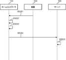
- it is a sequence diagram which shows the flow of the process in which a home controller acquires home information from a server.
- when the home controller is connected to the network it is a sequence diagram showing a flow of processing in which the home controller detects a device on the network.
- a device when a device is connected to a network, it is a sequence diagram showing a flow of processing in which a home controller detects a device on the network. It is a flowchart which shows the flow of the process which a home controller controls an apparatus in one embodiment of this invention. It is a flowchart which shows the flow of the process which a home controller controls an apparatus in one embodiment of this invention. It is a flowchart which shows the flow of the process which a home controller produces
- it is a sequence diagram which shows the flow of the process in which a home controller directly controls an apparatus. In one embodiment of this invention, it is a sequence diagram which shows the flow of the process in which a home controller controls an apparatus via a server. In one embodiment of the present invention, it is a sequence diagram showing a flow of processing in which the home controller acquires the state of the device from the server. In one embodiment of the present invention, when the home controller controls a plurality of devices in one operation, it is a sequence diagram showing a flow of processing in which the home controller directly controls the devices.
- the home controller when the home controller controls a plurality of devices in one operation, it is a sequence diagram showing a flow of processing in which the home controller controls the devices via a server. In one embodiment of the present invention, when the home controller controls a plurality of devices in one operation, it is a sequence diagram showing a flow of processing in which the home controller controls the devices via a server. In one embodiment of the present invention, it is a sequence diagram showing the flow of processing when the device icon is moved in the home controller. In one embodiment of the present invention, it is a sequence diagram showing a flow of processing to update the device list of the home controller and the server. In one embodiment of the present invention, it is a sequence diagram showing a flow of processing to update the device list of the home controller and the server.
- FIG. 52 it is a sequence diagram showing a flow of processing to update the device list of the home controller and the server.
- FIG. 60 is a diagram showing a configuration of a basic screen adopting the floor plan shown in FIG. 59.
- FIG. 60 is a diagram showing a display state of a device control screen when the floor plan shown in FIG. 59 is adopted.
- FIG. 60 is a diagram illustrating a floor plan displayed on the display when the user performs an operation of pinching out a room in the floor plan illustrated in FIG. 59.
- FIG. 63 is a diagram showing a display state of the device control screen in the enlarged floor plan shown in FIG. 62. It is a figure which shows the screen transition from the display state of a basic screen to the display state of an apparatus control screen.
- FIG. 60 is a diagram illustrating a configuration of a basic screen when a mode in which a device icon is not displayed is employed in the basic screen in which the floor plan illustrated in FIG. 59 is employed.
- FIG. 6 is a diagram illustrating screen transition from a display state of a basic screen to a display state of a device control screen when a basic screen that does not display a device icon is employed. It is a figure which shows the structure of home information at the time of employ
- FIG. 53 is a diagram showing a configuration of a device list managed by a home controller when the floor plan shown in FIG. 52 is adopted. In one embodiment of this invention, it is a figure which shows an example of the control screen of the illuminating device displayed on the display of a home controller.
- a display screen of a display of a home controller transitions between a basic screen and a control screen of a lighting device.
- a display screen of a display of a home controller transitions between a basic screen and a control screen of a lighting device.
- the display screen of the home controller transitions between a lighting device control screen when the lighting device is on and a lighting device control screen when the lighting device is off.
- the display screen of the home controller display is between the basic screen, the lighting device control screen when the lighting device is on, and the lighting device control screen when the lighting device is off.
- it is a diagram illustrating an example in which a display screen of a home controller transitions when a device icon of one lighting device is shared for control of lighting devices in a plurality of rooms.
- FIG. 1 it is a diagram illustrating an example in which a display screen of a home controller transitions when a device icon of one lighting device is shared for control of lighting devices in a plurality of rooms.
- FIG. 1 it is a figure which shows another example of arrangement
- the display screen of the display of the home controller is a diagram showing an example of transition between the first floor display state on the basic screen and the control screen display state of the lighting equipment on the first floor. is there.
- it is a diagram showing an example in which the display screen of the home controller display is changed by the on / off control of the lighting device using the enlarged control screen of the lighting device.
- it is a diagram showing an example in which the display screen of the home controller transitions due to the light amount control of the lighting device using the enlarged control screen of the lighting device.
- it is a flowchart which shows the flow of the process in which a home controller controls lighting equipment.
- it is a flowchart which shows the flow of the process in which a home controller controls lighting equipment.
- it is a flowchart which shows the flow of the process which a home controller produces
- the home controller when the home controller controls a plurality of lighting devices in one operation, it is a sequence diagram showing a flow of processing in which the home controller directly controls the lighting devices. In one embodiment of the present invention, when the home controller controls a plurality of lighting devices in one operation, it is a sequence diagram showing a flow of processing in which the home controller controls the lighting devices via a server. In one embodiment of the present invention, when the home controller controls a plurality of lighting devices in one operation, it is a sequence diagram showing a flow of processing in which the home controller controls the lighting devices via a server.
- FIG. 53 is a diagram showing an example of a basic screen displayed on the display of the home controller when the floor plan described with reference to FIG. 52 is used in the embodiment of the present invention.
- FIG. 99 is a diagram illustrating an example of a control screen of a lighting device displayed on a display when a lighting device icon is selected on the basic screen illustrated in FIG. 98 in the embodiment of the present invention.
- FIG. 57 is a diagram showing an example of a basic screen displayed on the display of the home controller when the floor plan described with reference to FIG. 56 is used in the embodiment of the present invention.
- FIG. 100 is a diagram illustrating an example of a control screen of a lighting device displayed on a display when a device icon of the lighting device is selected on the basic screen illustrated in FIG. 100 according to the embodiment of the present invention.
- FIG. 60 is a diagram showing an example of a basic screen displayed on the display of the home controller when the floor plan described with reference to FIG.
- FIG. 105 is a diagram showing an example of a control screen of the lighting device displayed on the display when the device icon of the lighting device is selected on the basic screen shown in FIG. 102 in the embodiment of the present invention. In one embodiment of this invention, it is a figure which shows the example by which the apparatus icon of the common lighting equipment was arrange
- one or more target device icons are displayed on the right side of the monitor screen, and a floor plan is displayed on the left side of the monitor screen.
- the icons of one or more target devices and the floor plan are displayed separately, and the icons of the one or more target devices are not movable. For this reason, the installation location of the target device to be operated in the floor plan is specified by moving the pointer.
- an operation screen is displayed.
- Patent Document 1 Due to the above configuration, in Patent Document 1, the number of steps until the desired target device is operated increases from (i) to (iv). Therefore, when remotely monitoring or remotely controlling one or more target devices using one remote controller, the operation steps (i) to (iv) are required for the operation of each target device, and the operation becomes complicated. In this case, the number of processing steps can be increased in a stage until one desired target device among the one or more target devices is operated only by combining the remote controllers of one or more target devices into one. A request is made to the portable information terminal, and a larger number of processing operations is requested from the user.
- Patent Document 2 only the status display of each target device is described, and there is no description to remotely control the operation of each target device. Therefore, although one or more target devices can be remotely monitored using one remote controller, remote control is not possible.
- the opening / closing operation and state confirmation of the electric building materials are remotely controlled and monitored using a personal computer.
- the operation screen is displayed and operated. Accordingly, the number of steps until the desired target device is operated increases accordingly. Therefore, when remotely monitoring or remotely controlling one or more target devices using one remote controller, compared to using individual remote controllers for each of the one or more target devices, As many remote controllers as the target device are combined into one, the number of processing operations is requested to the portable information terminal in the stage until the operation of the desired one target device is reached. To the user.
- Patent Document 4 similarly to Patent Document 3, an operation screen for operating the lighting device and confirming the situation is separately provided (FIG. 8B). Accordingly, the number of steps from when the operation screen is started up to when the desired target device is operated increases by the amount of operation on the operation screen. Therefore, when remotely monitoring or remotely controlling one or more target devices using one remote controller, compared to using individual remote controllers for each of the one or more target devices, As many remote controllers as the target device are combined into one, the number of processing operations is requested to the portable information terminal in the stage until the operation of the desired one target device is reached. To the user.
- the lighting device in the room corresponding to the first target region can be turned on by moving the icon from the outside of the first target region to the inside of the first target region.
- the icon moves to the inside of the second target area.
- the lighting device in the room corresponding to the target area is turned on, the icon leaves the outside of the first target area, so that the lighting device in the room corresponding to the first target area is turned off. .
- the icon is located outside the target area as an initial position, and is moved to the inside of the target area to adjust the lighting device, so that two or more rooms are used.
- the operation of moving the icon itself into each of the two or more target areas becomes complicated. In particular, if the two rooms where the lighting device is to be turned on are not adjacent rooms but separate rooms, the operation becomes complicated.
- One embodiment of the present invention provides: A method for controlling a portable information terminal having a display connected to a network for controlling one or more target devices, For the portable information terminal computer, A display screen representing a floor plan including at least two rooms is displayed on the display; A device icon representing each of the one or more target devices is displayed on a display screen representing the floor plan, and a lighting icon representing a lighting device in the one or more target devices is included in the floor plan. Used in one or more rooms, Selection of the lighting icon is detected; If the selection of any region in one of the at least two rooms included in the floor plan is detected after the selection of the lighting icon is detected, the one room in which the selection is detected The first control command for controlling ON / OFF of the power supply of the lighting equipment corresponding to is output to the network.
- the lighting icon representing the lighting device in the one or more target devices is used in common in at least two or more rooms included in the floor plan, and the selection of the lighting icon is detected, and the lighting is detected. If selection of any area in one of the at least two rooms included in the floor plan is detected after selection of the icon is detected, it corresponds to the one room in which the selection is detected A first control command for controlling ON / OFF of the power supply of the lighting equipment is output to the network.
- the selection is detected only by detecting the selection of any region in one of the at least two rooms included in the floor plan.
- a separate operation screen is not provided as an operation screen for operating ON / OFF of the lighting device corresponding to one room, but the floor plan already displayed is used. For this reason, ON / OFF of the lighting equipment corresponding to the one room where the selection is detected can be controlled without separately displaying an operation screen for operating ON / OFF of the lighting equipment.
- the floor plan itself is used as an operation screen to turn on / off the lighting device corresponding to the room where the selection is detected.
- the display of a floor plan is not only used for displaying the operating state of the lighting device as in Patent Document 2, but can also be used for remote operation of the lighting device.
- the lighting device included in the room in which the lighting icon is selected is a control target. It is recognized. Subsequently, when the selection of any region in the room in which the selection of the lighting icon is detected is detected, ON / OFF of the power supply of the lighting device corresponding to the room is controlled. Therefore, as in the case where the above-mentioned Patent Document 5 is applied to a display screen showing a floor plan including two or more rooms, it is troublesome to move the icon from the outside of each target area to the inside of each target area. Operation is unnecessary.
- the power ON / OFF of the lighting device corresponding to the room can be easily controlled by a simple operation of selecting any region in the room to be controlled.
- the ON / OFF of the lighting device is not controlled by moving the icon from outside each target area into each target area. For this reason, every time the icon is moved from one room to the next adjacent room, the lighting device in the next room is turned off, although the lighting device in the next room is turned on. Inconvenience can be solved.
- the operation is simplified when the two rooms where the lighting device is to be turned on are not adjacent rooms but separate rooms.
- the display corresponding to the one room where the selection is detected on the display screen is displayed brightening more than a certain luminance
- a display corresponding to one room where the selection is detected may be displayed to be darker than the predetermined luminance
- the floor plan itself is also used as a screen for displaying the operating state of the lighting device. Therefore, a separate display screen is not used as a screen for displaying the operating state of the lighting device. Therefore, one or more steps until the status display screen is displayed separately from the floor plan as in Patent Document 1 and Patent Document 3 can be reduced, and the number of processing steps in the portable information terminal or the operation by the user The number can be reduced.
- the floor plan already displayed is used to indicate which room the lighting device to be controlled is located. It can be notified whether it is a lighting device.
- the lighting icon is shared and used in one or more rooms, it is possible to prevent an erroneous operation in which a user operates a lighting device in a different room by mistake.
- the floor plan itself not only the lighting device corresponding to the room where the selection is detected is operated ON / OFF, but also the operating state of the lighting device is displayed. For this reason, in addition to the remote operation of the lighting device, the same region that has already been displayed can be used to check the operating state of the lighting device. As a result, it is possible to provide a remote operation screen for the lighting device and a confirmation screen for the operating state of the lighting device by effectively utilizing display resources.
- At least two or more rooms included in the floor plan after the selection of any region in one of the two or more rooms included in the floor plan is detected.
- an on / off control command for controlling ON / OFF of the power supply of the lighting device corresponding to the other room where the selection is detected is sent to the network. You may make it output.
- an operation for operating ON / OFF of the lighting device corresponding to the other room is detected only by detecting that any region in another room different from the one room is selected.
- an operation screen is not separately provided, but the floor plan is used. Therefore, ON / OFF of the lighting device corresponding to the other room is controlled without displaying an operation screen for operating ON / OFF of the lighting device provided in the area corresponding to the other room.
- the floor plan itself is used as an operation screen to turn on / off the lighting device corresponding to the certain room. For this reason, not only the operation state of the lighting device is simply displayed as in Patent Document 2, but also remote operation of the lighting device can be realized.
- the intensity of the light of the lighting device corresponding to the target area is not controlled by moving the icon from the outside to the inside of the target area.
- On / off control of the power supply of the corresponding lighting device is performed by detecting the selection of the area or the selection of any area in the other room. Therefore, each time the icon is moved from the one room to the other room, the lighting device in the other room is turned on, but the lighting device in the one room is turned off against the user's intention. Inconvenience can be solved.
- the illumination icon may be initially displayed outside the floor plan area represented by the display screen.
- the illumination icon is initially displayed outside the floor plan area represented by the display screen.
- the erroneous operation based on the user's erroneous recognition that the lighting icon is for a lighting device in a specific room can be prevented.
- the device icon representing each of the one or more target devices is evacuated outside the display area of the display screen representing the floor plan. May be.
- the floor plan can be displayed by display control that saves a device icon representing each of the one or more target devices by effectively using display resources that are already displayed without displaying another display screen. It can be shown that the displayed screen is in an operable state.
- the display is a touch panel display.
- the detection of the selection of the lighting icon or the selection of any area in the room where the selection of the lighting icon is detected may be performed by detecting a touch on the touch panel display.
- detection of the selection of the lighting icon or detection of selection of any region in the room where the selection of the lighting icon is detected may be detected by clicking a mouse pointer. Good.
- the display is a touch panel display.
- the amount of light of the lighting device is changed according to the amount of movement.
- a second control command may be sent to the network.
- the amount of movement including the amount of movement outside the area of the room is determined according to the amount of movement.
- a second control command may be sent to the network.
- the light quantity of the illumination device can be suitably changed regardless of the display size of the area corresponding to the room.
- the second control command may increase the light amount of the lighting device as the movement amount increases.
- the display is a touch panel display.
- the amount of light of the lighting device is changed according to the direction of the movement.
- the second control command to be sent may be sent to the network.
- the direction of movement including the direction of movement outside the room area depends on the direction of movement.
- the second control command may be sent to the network.
- the moving direction can be reliably detected. Therefore, the light quantity of the illumination device can be suitably changed regardless of the display size of the area corresponding to the room.
- the second control command may increase the amount of light of the lighting device when the moving direction is a direction on the display screen.
- the second control command may reduce the light amount of the lighting device when the moving direction is a direction on the display screen.
- the display is a touch panel display.
- the adjustment screen for adjusting the light amount of the lighting device corresponding to the room in which any one of the areas is selected Is displayed,
- a second control command for changing the amount of light of the lighting device according to the amount of movement may be sent to the network.
- the light amount of the lighting device can be changed in accordance with the amount of movement on the adjustment screen. Therefore, the light quantity of the illumination device can be suitably changed regardless of the display size of the area corresponding to the room.
- the display is a touch panel display.
- the adjustment screen for adjusting the light amount of the lighting device corresponding to the room in which any one of the areas is selected Is displayed,
- a second control command for changing the amount of light of the lighting device according to the direction of the movement may be sent to the network.
- the light amount of the lighting device can be changed on the adjustment screen according to the direction of movement. Therefore, the light quantity of the illumination device can be suitably changed regardless of the display size of the area corresponding to the room.
- the adjustment screen may have a display size larger than the display size of the area corresponding to the room in which any one of the areas is selected.
- the light quantity of the illumination device can be suitably changed regardless of the display size of the area corresponding to the room.
- the selection is performed by overlapping on a display screen representing the floor plan. You may make it display the control screen for either operation of the target apparatus corresponding to the performed apparatus icon, or status confirmation.
- a home controller capable of controlling one or more devices with one unit will be described.
- FIG. 1 is an overall configuration diagram of a home control system to which a home controller according to the present embodiment is applied.
- the home control system includes a home controller 100, a device 200 (an example of a target device), and a server 300.
- a home controller 100 and one or more devices 200 are arranged, and a server 300 is arranged in the cloud center.
- the home controller 100, the device 200, and the server 300 communicate with each other via a wired or wireless network.
- the device 200 and the home controller 100 are communicably connected to each other via a wireless or wired home network, and the home controller 100, the device 200, and the server 300 are mutually connected via an external network such as the Internet. It is connected so that it can communicate.
- the home controller 100 is not necessarily arranged in the house, and may be arranged outside the house. In this case, the user controls one or more devices 200 from the outside.
- a portable information terminal such as a smartphone or a tablet terminal is adopted.
- a button-type portable information terminal such as a mobile phone may be employed as the home controller 100.
- FIG. 2 is a diagram showing a main device 200 controlled by the home controller 100.
- the home controller 100 controls devices 200 such as an air conditioner 201, lighting devices 202 and 203, a bath 204, a refrigerator 205, a washing machine 206, a toilet 207, and a curtain 208.
- devices 200 such as an air conditioner 201, lighting devices 202 and 203, a bath 204, a refrigerator 205, a washing machine 206, a toilet 207, and a curtain 208.
- a plurality of devices 200 of the same type may be included in the devices 200 controlled by the home controller 100, such as the lighting device 202 and the lighting device 203.
- the device 200 such as the air conditioner 201 illustrated in FIG. 2 is merely an example, and a television, a Blu-ray recorder, an audio device, or the like may be employed as the device 200. That is, as the device 200, any device may be employed as long as it is an electric device having a function capable of communicating with the home controller 100.
- an electric device used in a general household is shown as the device 200, but the present embodiment is not limited to this, and an office device used in an office or the like may be adopted. Examples of office equipment include a printer, a personal computer, a scanner, and a copier.
- FIG. 3 is a block diagram illustrating configurations of the home controller 100, the device 200, and the server 300.
- the home controller 100 includes a display 101, a touch panel control unit 102, a display control unit 103, a storage unit 104, a device management unit 105, a device control unit 106, and a communication control unit 107.
- the display 101 is configured by a touch panel display, for example, and displays a user interface for the user to operate the home controller 100 and the like. The user can input various operations to the home controller 100 by touching the display 101.
- the touch panel control unit 102 When the touch panel control unit 102 recognizes a user operation on the display 101, the touch panel control unit 102 interprets the content of the operation and notifies the other components of the operation content. For example, if an object is displayed at a position on the display 101 tapped by the user, the touch panel control unit 102 determines that the object has been selected by the user. As the object, various GUI parts that accept user operations such as buttons are adopted.
- the display control unit 103 generates a GUI (Graphical User Interface) of the home controller 100 and causes the display 101 to display the GUI.
- the storage unit 104 stores information necessary for the operation of the home controller 100 such as a device list managed by the device management unit 105.
- the device management unit 105 manages the device 200 to be controlled using the device list stored in the storage unit 104. In addition, when the device 200 is connected to the home network, the device management unit 105 detects the device 200. Furthermore, the device management unit 105 acquires home information 2700 (to be described later) from the server 300, and stores and manages the acquired home information 2700 in the storage unit 104. The device control unit 106 issues a control command to the device 200.
- the communication control unit 107 controls communication between the home controller 100 and the device 200 and communication between the home controller 100 and the server 300. In addition, the communication control unit 107 receives various data transmission requests from other blocks, transmits them to the device 200 or the server 300, receives data transmitted from the device 200 or the server 300, and sets the corresponding blocks. hand over.
- the display 101 may be a normal display instead of a touch panel display.
- the user may use an external input device such as a mouse (not shown) to move the pointer displayed on the display 101, click a desired object, and input an object selection instruction. That is, in the present embodiment, a series of operations performed by the user touching the display 101 can be replaced with operations for moving or clicking the pointer using an external input device such as a mouse.
- the device 200 includes a control execution unit 201, a state management unit 202, a storage unit 204, and a communication control unit 207.
- the control execution unit 201 receives a control command from the home controller 100 or the server 300, and controls the device 200 according to the received control command.
- the control content of the device 200 by the control execution unit 201 differs depending on the type of the device 200. For example, if the device 200 is a lighting device, the control execution unit 201 turns the lighting device on and off.
- the control execution unit 201 transmits the execution result of the control command and the state of the device 200 to the home controller 100 and the server 300.
- the state management unit 202 manages the state of the device 200.
- the management content of the device 200 by the state management unit 202 differs depending on the type of the device 200. For example, if the device 200 is a lighting device, the state management unit 202 manages whether the lighting device is currently in an on state or an off state.
- the storage unit 204 stores information related to the state of the device 200 managed by the state management unit 202.
- the communication control unit 207 controls communication between the device 200 and the home controller 100 and communication between the device 200 and the server 300. In addition, the communication control unit 207 receives various data transmission requests from other blocks, transmits them to the home controller 100 or the server 300, receives data transmitted from the home controller 100 or the server 300, and applies. Pass to block.
- the server 300 includes a home information management unit 301, a device control unit 302, a storage unit 304, and a communication control unit 307.
- the home information management unit 301 manages home information 2700 described later for each house or each user account.
- the home information management unit 301 transmits home information 2700 to the home controller 100 in response to a request from the home controller 100.
- the home information management unit 301 acquires log information related to the usage history of the device 200 and information related to the state of the device 200 from the device 200, and stores and manages the acquired information in the storage unit 304.
- the device control unit 302 transmits a control command to the device 200 in response to a request from the home controller 100.
- the storage unit 304 stores information necessary for the operation of the server 300 such as home information 2700 managed by the home information management unit 301 and information related to the state of the device 200. Similar to the communication control unit 107, the communication control unit 307 controls communication between the server 300 and the home controller 100 and communication between the server 300 and the device 200. In addition, the communication control unit 307 receives various data transmission requests from other blocks, transmits the requests to the home controller 100 or the device 200, and receives data transmitted from the home controller 100 or the device 200. Pass to block.
- FIG. 4 is a diagram illustrating a configuration example of an implementation form of the home controller 100.
- the home controller 100 includes an application 401, an OS (Operating System) 402, a memory 403, and other hardware not shown.
- OS Operating System
- Application 401 is application software for causing the portable information terminal to function as the home controller 100, and is executed by the processor of the home controller 100.
- the home controller 100 may implement the application 401 by reading the application 401 from a computer-readable recording medium, or may implement the application 401 by downloading from a network.
- the OS 402 is basic software of the portable information terminal and is executed by the processor of the home controller 100.
- the memory 403 is configured by a storage device such as a RAM and a ROM provided in the home controller 100 and stores a data group included in the application 401.
- the processor of the home controller 100 executes the application 401
- the memory 403 functions as the storage unit 104 when the processor of the home controller 100 executes the application 401.
- the home controller 100 may be implemented solely by the application 401, may be implemented by the application 401 and the OS 402, or may be implemented by the application 401, the OS 402, and the memory 403.
- the application 401, the OS 402, the memory 403, and other hardware may be implemented.
- a computer is constituted by, for example, a processor and a storage device constituting the portable information terminal.
- the processor any one of CPU, FPGA, and ASIC, or a combination of two or more thereof is employed.
- the storage device for example, any one of ROM, RAM, and hard disk, or a combination of two or more thereof is employed.
- FIG. 5 is a diagram showing a basic screen configuration of the home controller 100.
- the basic screen of the home controller 100 displayed on the display 101 includes a floor plan 500, a device icon 501, and a device list display change button 503.
- the floor plan 500 is a bird's-eye view that planarly represents the arrangement and shape of one or more rooms constituting each floor of the house.
- a floor plan 500 is also prepared for each floor. For example, when the house is composed of two floors, as shown in FIG. 6, the floor plan 500 is displayed on the display 101 as the floor plan 601 of the first floor and the floor plan 602 of the second floor. .
- the device icon 501 is an icon representing the device 200 displayed on the floor plan 500 in an overlapping manner.
- the touch panel control unit 102 detects a tap on the device icon 501 by the user, the display control unit 103 displays a device control screen 502 described later on the display 101. As a result, the user can control the device 200 by operating the device control screen 502.
- a device icon 501 is prepared for each device 200.
- the display control unit 103 arranges the device icon 501 on the floor plan 500 based on the actual arrangement of the device 200 in the home.
- Information about where the device icon 501 is arranged in the floor plan 500 is registered in an arrangement 3104 of the device list 3100 described later.
- a position on the floor plan 500 corresponding to the actual arrangement position of the device 200 is registered in the arrangement 3104. Therefore, the display control unit 103 arranges the device icon 501 at the position registered in the arrangement 3104 of the device list 3100, so that the device icon 501 is placed at a position on the floor plan 500 corresponding to the actual arrangement position of the device 200. Can be arranged.
- one floor is divided into a plurality of rooms by partition lines indicating room partitions. Therefore, the user can recognize at a glance what kind of device 200 is placed in which room.
- a schematic image of furniture is displayed at a position on the floor plan 500 corresponding to the actual arrangement position of the furniture.
- an image showing the range of motion of the door is displayed at a position on the floor plan 500 corresponding to the actual arrangement position of the door.
- a staircase image is displayed at a position on the floor plan 500 corresponding to the arrangement position of the staircase. Therefore, the user can recognize at a glance the position of furniture arranged in each room and the positions of stairs and doors on the floor.
- a button described as “to list UI” displayed at the lower right of the basic screen is a device list display change button 503, and switches the screen display from the basic screen to a device list display screen (see FIG. 24) described later. It is a button for.
- the touch panel control unit 102 detects a user tap on the device list display change button 503, the display control unit 103 switches the screen display of the display 101 from the basic screen to the device list display screen.
- the display control unit 103 may hide the device list display change button 503.
- one device icon 501 corresponds to one device 200, but the present embodiment is not limited to this, and one device icon 501 corresponds to a plurality of devices 200, and a plurality of devices.
- One device icon 501 may be shared by 200. For example, when there are two lighting devices in the living room, these two lighting devices may be represented by one device icon 501.
- the display control unit 103 causes the display 101 to display a device control screen 502 that can control both lighting devices at the same time.
- the user can control two lighting devices simultaneously.
- a large room such as a living room
- a plurality of lighting devices are often arranged.
- the user often turns on or off all the lighting devices instead of turning on or off some of the lighting devices arranged in the living room.
- the number of operations by the user can be reduced. Therefore, it is only necessary to adopt a mode in which one device icon 501 is associated with a plurality of devices 200 that are likely to be operated simultaneously by the user, and one device control screen 502 is displayed.
- the display control unit 103 may display the device icon 501 at a position on the floor plan 500 corresponding to the actual arrangement position of any one device 200. .
- the display control unit 103 may display a device icon 501 representing the plurality of devices 200 at a predetermined place in a room where the plurality of devices 200 are arranged.
- the user moves the device icon 501 to an appropriate position in the floor plan 500 in order to place the device icon 501 on the floor plan 500 based on the actual arrangement of the device 200 in the house.
- the user can move the device icon 501 to an arbitrary position by dragging while holding down the device icon 501. These are executed when the device icon 501 is added, such as when the home controller 100 is used for the first time or when the device 200 is newly purchased.
- the device management unit 105 registers the position on the floor plan 500 of the moved device icon 501 in an arrangement 3104 of the device list 3100 described later. As a result, a position on the floor plan 500 corresponding to the actual arrangement position of the device 200 is registered in the arrangement 3104.
- the initial display position of the device icon 501 may be determined in advance by the system. For example, a predetermined position outside the display area of the floor plan 500 or a predetermined position in a predetermined room on the floor plan 500 is adopted. can do. Note that the method of arranging the device icon 501 on the floor plan 500 based on the actual arrangement of the device 200 in the home is not limited to this, and the following method may be used.
- Some floor plans 500 include arrangement information of device icons 501 as shown in FIGS. 7, 8, and 9.
- text indicating the type of the device 200 represented by the device icon 501 to be placed is written at the position where the device icon 501 is to be placed.
- an image indicating the type of the device 200 represented by the device icon 501 to be placed is described at the position where the device icon 501 is to be placed.
- an image in which the type of the device 200 represented by the device icon 501 to be arranged is simply indicated by a circle or a square is described at the position where the device icon 501 is to be arranged. Yes.
- the display control unit 103 automatically places the device icon 501 on the floor plan 500 based on the placement information described in the floor plan 500. Then, the basic screen of FIG. 5 may be generated. In this case, the user need not perform an operation of moving the device icon 501 to an appropriate position in the floor plan 500.
- the display control unit 103 detects the position where the text “TV” is described, and automatically arranges the TV device icon 501 at that position. At the same time, the detected position is registered in the arrangement 3104 of the device list 3100.
- the display control unit 103 detects the position where the “TV” image is described, and automatically arranges the TV device icon 501 at that position. At the same time, the detected position is registered in the arrangement 3104 of the device list 3100. Further, in the example of the floor plan 4601 of the first floor in FIG. 9, the display control unit 103 detects a position where an image of a “circle filled with diagonal lines” is described, and a television device icon 501 is detected at that position. Are automatically arranged, and the detected position is registered in the arrangement 3104 of the device list 3100.
- the display control unit 103 can recognize the arrangement information included in the floor plan 500 and detect the display position of the arrangement information by using a commonly used text recognition technology or image recognition technology.
- FIG. 10 is a diagram for explaining a method of switching the floor display on the basic screen of the home controller 100.
- the case where the house is comprised by two floors, the 1st floor and the 2nd floor is illustrated.
- the touch panel control unit 102 detects a tap on the staircase region 603 of the first floor by the user. Then, the display control unit 103 switches the floor display of the basic screen from the first floor to the second floor.
- the touch panel control unit 102 detects a tap on the stair area 604 of the second floor by the user. Then, the display control unit 103 switches the floor display of the basic screen from the second floor to the first floor.
- the touch panel control unit 102 It may be determined that the staircase region 603 has been tapped.
- the floor display can be switched not only by tapping the staircase region 603 but also by a swipe operation of the display 101.
- the touch panel control unit 102 detects that the user performs a swipe operation from the right to the left on the display 101 in a state where the floor plan 601 of the first floor is displayed on the basic screen of the home controller 100. Then, the display control unit 103 switches the floor display of the basic screen from the first floor to the second floor. Similarly, the touch panel control unit 102 detects that the user performs a swipe operation from the left to the right on the display 101 while the floor plan 602 of the second floor is displayed on the basic screen of the home controller 100. Then, the display control unit 103 switches the floor display of the basic screen from the second floor to the first floor. Note that switching may be performed by a swipe operation in the vertical direction.
- FIG. 11 is a diagram illustrating a configuration of a display state of the device control screen 502 of the home controller 100.
- the touch panel control unit 102 detects that the user has selected the device icon 501 on the basic screen illustrated in FIG. 5, the display control unit 103 displays the device control screen 502 corresponding to the selected device icon 501 on the display 101.
- the device control screen 502 is unique to each device 200 and is a control screen for controlling or checking the state of the device 200.
- FIG. 11 shows an example in which the air conditioner device icon 801 is selected by the user, and the air conditioner temperature setting and the wind direction are controlled using the air conditioner device control screen 502.
- An image of the air conditioner is displayed on the device control screen 502, and the user can quickly recognize that the device control screen 502 is of an air conditioner, thereby preventing erroneous operation.
- An image showing the wind direction is displayed below the image of the air conditioner, and the user can select a desired wind direction by repeatedly tapping the image, for example.
- the numerical value displayed in the device control screen 502 indicates the current set temperature of the air conditioner.
- the upward triangle button is a temperature increase button
- the downward triangle button is a temperature decrease button.
- the set temperature of the air conditioner increases by a predetermined temperature (for example, 0.5 degrees), and when the temperature decrease button is pressed once, the set temperature of the air conditioner decreases by a predetermined temperature (for example, 0.5 degrees). To do.
- the first method is a method of arranging the device icon 501 outside the display area of the device control screen 502 as shown in FIG.
- the touch panel control unit 102 detects that a certain device icon 501 is tapped by the user, the display control unit 103 is outside the display region of the device control screen 502 regardless of whether or not it is within the display region of the floor plan 500.
- All device icons 501 are arranged in the display area of the display 101.
- the device icon 501 is arranged in an elliptical shape so as to surround the device control screen 502.
- the display control unit 103 displays all device icons 501 outside the display area of the device control screen 502. Is evacuated.
- the device icon 501 is hidden by the device control screen 502. Therefore, when the user tries to display the device control screen 502 of the device 200 different from the device 200 on which the device control screen 502 is currently displayed, the user temporarily deletes the currently displayed device control screen 502. Thus, there is no need to perform an operation of searching for the device icon 501 of the corresponding device 200.
- the display control unit 103 determines an arrangement position of each device icon 501 on the outer periphery of an ellipse having a predetermined shape according to the size of the device control screen 502, and places the device icon 501 at that position. What is necessary is just to arrange.
- a method for determining the arrangement position for example, a method of arranging all the device icons 501 to be displayed at equal intervals on the outer periphery of the ellipse may be adopted, or the adjacent device icon 501 and the center of the ellipse may be formed.
- a method of arranging the device icons 501 so that the angles are equal may be employed.
- the display control unit 103 divides the outer periphery of the ellipse into four regions, upper, lower, left, and right on the device control screen 502, and sets the device icons 501 so that the number of device icons 501 is equal and arranged at equal intervals in each region. You may arrange.
- the device icon 501 that has been arranged at the closest position on the floor plan 500 may be arranged at the determined arrangement position.
- the device icons 501 are arranged in an elliptical shape, but the present embodiment is not limited to this, and the device icons 501 may be arranged in a circular shape. In this case as well, the arrangement position of the device icon 501 may be determined using the same method as when the device icons 501 are arranged in an elliptical shape. In addition, as the arrangement shape of the device icon 501 when the device icon 501 is retracted outside the display area of the device control screen 502, a polygon such as a triangle, a quadrangle, or a pentagon may be employed.
- the second method is a method in which the device icons 501 are arranged in a line outside the display region of the device control screen 502 and the floor plan 500 and within the display region of the display 101 as shown in FIG.
- the touch panel control unit 102 detects that a certain device icon 501 has been tapped by the user
- the display control unit 103 arranges all the device icons 501 in one vertical column on the left side of the display area of the floor plan 500. That is, the display control unit 103 saves all the device icons 501 in an empty area outside the display area of the floor plan 500 and in the display area of the display 101.
- the device icons 501 are arranged on the left side of the floor plan 502.
- the present embodiment is not limited to this, and may be arranged in a vertical column on the right side of the floor plan 502.
- the floor plan 500 may be arranged in one horizontal row on the upper side or the lower side.
- the display control unit 103 swipes the device icons 501 arranged in one column on the left side upward or downward. In response to the swipe operation, the device icon 501 may be scrolled upward or downward to display the non-displayed device icon 501 in the display 101.
- the device icon 501 that has not been displayed is displayed in the display 101, and the user can select the device icon 501.
- the display control unit 103 swipes the device icons 501 arranged in the first horizontal row leftward or rightward. Then, the device icon 501 may be scrolled leftward or rightward according to the swipe operation, and the non-displayed device icon 501 may be displayed in the display 101.
- the display control unit 103 may display the device icon 501 selected by the user in a display mode different from the device icon 501 not selected. Thereby, the user can easily recognize the selected device icon 501.
- the display control unit 103 may display the selected device icon 801 in a color different from that of the other device icons 501 that are not selected. Specifically, the display control unit 103 may display the color of the background portion of the selected device icon 501 in a color different from the color of the background portion of the device icon 501 that has not been selected. However, this is only an example, and the display control unit 103 may make the brightness of the selected device icon 501 brighter than that of the unselected device icon 501, or the concentration of the selected device icon 501. The device icon 501 that is not selected may be darker, or the selected device icon 501 may be blinked at a constant cycle.
- the device icon 501 selected by the user may be arranged separately from the device icon 501 that has not been selected. Thereby, the user can easily recognize the selected device icon 501.
- the display control unit 103 may arrange the selected device icon 901 at the uppermost position on the outer periphery of the ellipse.
- the display control unit 103 may arrange the selected device icon 501 at a specific position (for example, the lowermost end, the rightmost end, or the leftmost end) on the outer periphery of the ellipse.
- the display control unit 103 may arrange the device icon 501 selected by the user in a specific place where the user can easily recognize.
- the display control unit 103 may scroll the arrangement of the device icons 501 so that the selected device icon 1101 is arranged in the display area of the display 101.
- the device icon 501 is scrolled so that the selected device icon 1101 is arranged at the center of the icon row displayed in the vertical column on the left side of the floor plan 500.
- the user can easily recognize the selected device icon 501.
- the device icon 1101 is arranged at the center of the icon row, but may be any other position as long as it is a conspicuous position, for example, the top of the icon row or the top of the icon row. It may be arranged below.
- the arrangement order of the device icons 501 when the device icons 501 are evacuated outside the display area of the floor plan 500 is, for example, the device 200 whose arrangement position on the floor plan 500 is close to the device icon 501 selected by the user.
- the order of arrangement near the selected device icon 501 may be adopted. Or you may employ
- the device icon 501 of the television when the device icon 501 of the television is selected by the user, the device icon 501 of the Blu-ray recorder may be displayed beside the device icon 501.
- a table indicating combinations of devices 200 that are likely to be used simultaneously is stored in the storage unit 104 in advance, and the arrangement of the device icons 501 may be determined according to this table.
- the display control unit 103 may arrange the device icons 501 by grouping them according to specific conditions.
- device icons 501 are grouped according to the place where the device 200 is arranged.
- the devices 200 arranged in the living room are grouped as device icons 1201, the devices 200 arranged in the bathroom are grouped as device icons 1202, and the devices 200 arranged in the bedroom are grouped as device icons 1203. .
- a display order is set for each group, and the grouped device icons 501 are arranged in one vertical column on the left side of the floor plan 500 according to the display order.
- the display order of the groups for example, the order of the room group located closer to the room where the device 200 selected by the user is closer to the room group where the device 200 selected by the user is closer. Adopt it.
- the display control unit 103 may group and arrange the device icons 501 for each type of the device 200.
- the display control unit 103 may continuously arrange the device icons 501 of the devices 200 of the same type, and group the device icons 501 for each type.
- the display control unit 103 may determine the type of the device 200 in accordance with the contents registered in the device type 3102 of the device list 3100 (see FIG. 35).
- the device icons 501 of the devices 200 of the same type are grouped into one group, but the present embodiment is not limited to this.
- the display control unit 103 may classify the devices 200 into categories according to the types, group the device icons 501 for each category, and arrange them on the left side of the floor plan 500.
- the three device icons 501 of the refrigerator, the microwave oven, and the dishwasher are classified into cooking appliance categories. They are grouped as 2303 and arranged on the left side of the floor plan 500.
- Entertainment device categories include devices 200 such as televisions, recorders, players, and home theaters. Further, the category of air conditioners includes devices 200 such as air conditioners, air purifiers, humidifiers, dehumidifiers, and residential air circulation facilities.
- device icons 501 of a television, a recorder, an air conditioner, and an air purifier are arranged on the floor plan 500, and the television device icon 501 is selected by the user, the televisions classified into the category of entertainment devices and The recorder device icons 501 are grouped into one and arranged on the left side of the floor plan 500, and the air conditioner and air purifier device icons 501 classified into the air conditioner category are grouped into one and the left side of the floor plan 500. Placed in.
- the display control unit 103 may determine the category of the device 200 from the contents registered in the device type 3102 of the device list 3100.
- a classification table for classifying the category of the device 200 from the contents registered in the device type 3102 is stored in the storage unit 104 in advance, and the display control unit 103 refers to this classification table and the category of the device 200 is stored. Can be determined.
- a method of classification according to the type of the device 200 various methods other than the above can be adopted. For example, as shown in FIG. 24, a method of classifying into household appliances, air conditioning, and equipment is adopted. May be.
- the method of grouping and arranging the device icons 501 based on specific conditions can also be applied to a display mode in which the device icons 501 are retracted so as to surround the device control screen 502 as shown in FIG. Applicable.
- FIGS. 17A and 17B are diagrams showing a display method of the floor plan 500 in a state where the device control screen 502 is displayed. As shown in FIGS. 17A and 17B, there are two types of display methods of the floor plan 500. The first is a display method in which the entire floor plan 500 is covered with a semi-transparent gray layer (shown as halftone dots in the drawing) as shown in FIG.
- the gray layer is image data having a low-lightness color such as gray and having a predetermined transparency.
- the display control unit 103 determines the display order of the device control screen 502, the gray layer, and the floor plan 500 in the order that the device control screen 502 is the highest layer and the floor plan 500 is the lowest layer. What is necessary is just to synthesize an image. Thereby, it is possible to prevent the device control screen 502 from being covered with a gray layer and displayed.
- the non-control target area 1302 is covered with a semi-transparent gray layer in the floor plan 500 (halftone dot area in the figure), and the control target area This is a display method in which 1301 is not covered with a translucent gray layer.
- the control target area 1301 indicates an area on the floor plan 500 in which the device 200 represented by the device icon 501 selected by the user is arranged, and the non-control target area 1302 is a floor plan other than the room. It refers to the area above 500.
- the control target device is an air conditioner installed in a living room
- the control target area 1301 is a living area of the floor plan 500
- the non-control target area 1302 is an area other than the living room of the floor plan 500.
- the display control unit 103 specifies the position (X10, Y100, Z1) of the air conditioner from the contents registered in the air conditioner arrangement 3104.
- the display control unit 103 refers to the room information 2900 and determines in which room the specified position (X10, Y100, Z1) is located.
- the position (X10, Y100, Z1) is located in a region surrounded by the vertices having vertex IDs F, G, H, I, L, O, and N.
- the display control unit 103 determines that the air conditioner is placed in the living room whose room ID is A.
- the display control unit 103 generates a gray layer having the living area as the control target area 1301 and the other area on the floor plan 500 as the non-control target area 1302.
- the user selects the device icon 501 of the device 200 (here, air conditioner) that the user wants to control, and the touch panel control unit 102 detects the selection. Then, the display control unit 103 overlaps and displays the device control screen 502 corresponding to the selected device icon 501 on the floor plan 500 as shown in the right diagram of FIG. As a result, the display state of the basic screen changes to the display state of the device control screen 502.
- the device icon 501 of the device 200 here, air conditioner
- the touch panel control unit 102 detects the selection.
- the display control unit 103 overlaps and displays the device control screen 502 corresponding to the selected device icon 501 on the floor plan 500 as shown in the right diagram of FIG.
- the display state of the basic screen changes to the display state of the device control screen 502.
- the air conditioner device icon 501 corresponding to the device control screen 502 or outside the display area of the device control screen 502 (for example, the device control screen 502
- the touch panel control unit 102 detects the tap.
- the display control unit 103 deletes the device control screen 502 and returns the display state of the device control screen 502 to the display state of the basic screen. At this time, the display control unit 103 returns the device icon 501 to the original arrangement position on the floor plan 500.
- the floor plan 500 displayed on the basic screen is.
- the basic screen displays the floor plan 602 of the second floor
- the user taps the device icon 501 of the device 200 (here, air conditioner) that the user wants to control
- the touch panel control unit 102 detects the tap.
- the display control unit 103 displays the device control screen 502 corresponding to the selected device icon 501 in an overlapping manner on the floor plan 602 on the second floor.
- the device icon 501 of the air conditioner corresponding to the displayed device control screen 502 or outside the display area of the device control screen 502 (for example, The user taps the floor plan 500 (display area outside the display area of the device control screen 502), and the touch panel control unit 102 detects the tap. Then, as shown in the left diagram of FIG. 19, the display control unit 103 deletes the device control screen 502, and changes from the display state of the device control screen 502 to the display state of the basic screen that displays the floor plan 602 of the second floor. return.
- the user taps the washing machine icon 501, which is a device icon 501 different from the air conditioner icon 501, and touches the tap on the touch panel.
- the control unit 102 detects it.
- the display control unit 103 deletes the displayed device control screen 502, and the device control screen 502 corresponding to the washing machine device icon 501 is overlaid on the floor plan 500. Wrap and display. The reverse is also true.
- the device control screen 502 is sequentially switched, so that the user can continuously control the different devices 200. That is, when another device control screen 502 is displayed while a certain device control screen 502 is displayed, the user does not need to input an operation for deleting the certain device control screen 502, and the device control screen 502 can be switched by one touch. it can.
- the display control unit 103 When the user taps the device icon 501 corresponding to the device control screen 502 being displayed in the display state of the device control screen 502, the display control unit 103 only deletes the device control screen 502, and the basic screen You don't have to go back to This screen transition is shown in FIG.
- the device control screen 502 of the air conditioner is displayed, and all the device icons 501 are displayed in one vertical column on the left side of the floor plan 500. Yes.
- the user taps the device icon 501 of the air conditioner, and the touch panel control unit 102 detects the tap.
- the display control unit 103 deletes only the device control screen 502 of the air conditioner while maintaining the vertical display of the device icon 501 as shown in the right diagram of FIG. In this case, since the device icon 501 does not move on the floor plan 500, it is possible to meet the user's request when only the floor plan 500 is to be displayed.
- the user selects an arbitrary device icon 501, and the touch panel control unit 102 detects the selection. Then, the display control unit 103 displays a device control screen 502 corresponding to the selected device icon 501. For example, in the right diagram of FIG. 21, when the user selects the air conditioner device icon 501 from the device icons 501 arranged in a vertical column on the left side of the floor plan 500, as shown in the left diagram of FIG. The device control screen 502 is displayed.
- the transition from the display state of the basic screen to the display state of the device control screen 502 is performed in animation will be described with reference to FIG.
- the user selects, for example, an air conditioner device icon 501 on the basic screen.
- the display control unit 103 gradually decreases the transparency of the air conditioner device control screen 502 in the order of the upper right diagram ⁇ the lower right diagram ⁇ the lower left diagram in FIG. 22 and finally sets the transparency to zero.
- the display control unit 103 moves all device icons 501 to the outer periphery of an ellipse surrounding the device control screen 502.
- the transition from the display state of the basic screen to the display state of the device control screen 502 is performed in animation will be described with reference to FIG.
- the user selects, for example, the device icon 501 of the air conditioner device 200.
- the display control unit 103 gradually decreases the transparency of the air conditioner device control screen 502 in the order of the upper right diagram ⁇ the lower right diagram ⁇ the lower left diagram in FIG. 23 and finally sets the transparency to zero.
- the display control unit 103 moves all device icons to the left side of the floor plan 500.
- the screen transition is animated to increase the user's interest in operating the device control screen 502 through screen rendering from when the device icon 501 is selected until the device control screen 502 is displayed. Can do.
- FIG. 24 is a diagram showing the configuration of the device list display screen.
- the device list display screen is displayed when the user taps the device list display change button 503 on the basic screen shown in FIG.
- the device list display screen includes a device list 2000, a device detail icon 2001, and a basic screen display button 2003.
- the display control unit 103 causes the device control screen 502 to overlap the device list 2000 to be displayed. Accordingly, the user can operate the device 200 by displaying the device control screen 502 in the same manner as when the device icon 501 is tapped.
- the device detail icon 2001 is prepared for each device 200.
- the device detail icon 2001 is different from the device icon 501 in that the device detail icon 2001 represents an on / off state and an operation state of the device 200 in addition to an image representing the device 200.
- the device detail icon 2001 displayed in the upper left of FIG. 24, in addition to the image of the refrigerator, “ON” indicating that the refrigerator is currently turned on, and “ The information “driving / ice” is displayed.
- the device detail icon 2001 is classified and displayed based on a predetermined classification standard.
- classification criteria determined in advance for example, the type of the device 200, the room in which the device 200 is arranged, the usage status of the device 200, or the like is employed.
- FIG. 24 illustrates the case where the type of the device 200 is used as the classification standard, and the device detail icons 2001 are classified into three categories: household appliances, air conditioning, and equipment.
- the refrigerator, the electric toothbrush, the washing machine, and the television are classified into the household appliance category
- the air conditioner and the air purifier are classified into the air conditioning category
- the toilet, the lighting device, and the bathtub are the facility category. It is classified.
- the storage unit 104 stores a classification table that determines whether each device 200 is classified into household appliances, air conditioning, or equipment from the contents registered in the device type 3102 of the device list 3100 (see FIG. 35). In advance. And the display control part 103 should just classify
- the button described as “to floor plan UI” displayed at the lower right of the device list 2000 is a basic screen display button 2003.
- a basic screen display button 2003 is a button for switching the screen from the device list display screen to the basic screen.
- the basic screen and the device list display screen can be switched, but the device list display screen can be used as a basic screen instead of the basic screen shown in FIG. In this case, the basic screen display button 2003 may be omitted.
- one device detail icon 2001 is associated with one device 200, but the present embodiment is not limited to this, and a plurality of devices 200 are associated with one device detail icon 2001, and a plurality of devices 200 are associated with each device.
- One device detail icon 2001 may be shared by the devices 200. For example, when there are two lighting devices in the living room, the two lighting devices may be represented by one device detail icon 2001.
- the display control unit 103 causes the display 101 to display a device control screen 502 that can control both lighting devices simultaneously.
- the same effect as when one device icon 501 is shared by a plurality of devices 200 can be obtained.
- the device detail icon 2001 may display the on / off state and the operation state of each of the two lighting devices.
- the device detail icon 2001 may be used instead of the device icon 501 on the basic screen, or the device icon 501 may be used instead of the device detail icon 2001 on the device list display screen.
- the device control screen 502 displayed when the device detail icon 2001 is selected may be the same as or different from the device control screen 502 displayed when the device icon 501 is selected. For example, since the device detail icon 2001 includes more information than the device icon 501, the device control screen 502 displayed when the device detail icon 2001 is selected displays the device icon 501. More buttons and states may be included than the device control screen 502 displayed.
- FIG. 25 is a diagram showing screen transition between the basic screen and the device list display screen.
- the device list display change button 503 is selected by the user on the basic screen shown in the left diagram of FIG. 25, the display of the display 101 is switched to the device list display screen shown in the right diagram of FIG.
- the display of the display 101 is switched to the basic screen shown in the left diagram of FIG.
- the display control unit 103 switches the display screen of the display 101 to the basic screen shown in the device list display screen.
- the touch panel control unit 102 detects the tap of the device list display change button 503 in the display state of the basic screen
- the display control unit 103 switches the display screen of the display 101 from the basic screen to the device list display screen.
- the device list display screen when the device list display screen is selected for display and the user tries to operate the television in front of the user, if there is only one television at home, the device list display screen displays the television device. Since only one detail icon 2001 is included, the user can directly select the device detail icon 2001 of the television without erroneous operation and display the device control screen 502 corresponding to the television.
- the device list display screen when the device list display screen is selected, it is possible to operate or check the status of each device 200.
- the device list display screen focuses on each device 200, the device 200 and the device 200 are displayed.
- the relationship with the place where is placed is unclear. Therefore, for example, for a plurality of devices 200 installed in the same building, such as an air conditioner or a lighting device, it is unclear which room's air conditioner or lighting device is a control target, and may cause an erroneous operation. is there.
- a basic screen is provided in addition to the device list display screen so that the basic screen and the device list display screen can be selected.
- the relationship between the device 200 and the place where the device 200 is arranged becomes clear. Therefore, for example, with regard to the same type of devices 200 installed in the same building, such as an air conditioner or a lighting device, it is easy to determine which room of the air conditioner or lighting device is a control target. It is possible to prevent an air conditioner or a lighting device installed in a different room from being erroneously operated.
- FIG. 26 is a diagram showing screen transitions between the display state of the device list display screen and the display state of the device control screen 502.
- the user selects the device detail icon 2001 of the device 200 (here, air conditioner) that the user wants to control, and the touch panel control unit 102 detects the selection.
- the display control unit 103 displays the air conditioner device control screen 502 corresponding to the selected device detail icon 2001 in an overlapping manner on the device list display screen, as shown in the right diagram of FIG.
- the display state of the device list display screen changes to the display state of the device control screen 502.
- the display control unit 103 hides the device detail icon 2001 other than the air conditioner selected by the user, and places only the device detail icon 2001 of the air conditioner at a position different from the device control screen 502. It is displayed. As a result, the user can clearly recognize the device detail icon 2001 selected by the user.
- the user selects the device detail icon 2001 of the air conditioner, and the touch panel control unit 102 detects the selection. Then, as shown in the left diagram of FIG. 26, the display control unit 103 deletes the device control screen 502 and returns the display state of the device control screen 502 to the display state of the device list display screen.
- the plurality of device detail icons 2001 may be displayed in a line at the edge of the screen as shown in FIG. 13, or may be displayed so as to surround the device control screen 502 as shown in FIG.
- the user can continuously select the device detail icon 2001 in the display state of the device control screen 502 and continuously display the other device control screen 502.
- the user does not need to input an operation for deleting the certain device control screen 502, and the device control screen 502 is switched with one touch. Can do.
- FIG. 27 is a diagram showing screen transition between the display state of the basic screen and the display state of the device control screen 502 when there are a plurality of device icons 501 representing the same type of device 200 on the basic screen.
- the device icon 501 of the television A is represented as a device icon 2401
- the device icon 501 of the television B is represented as a device icon 2402.
- the user can intuitively select and operate the television to be controlled from the floor plan 500.
- the right diagram of FIG. 27 shows an example in which the TV A device icon 2401 is selected and the TV A device control screen 2403 is displayed.
- each device icon 501 is arranged at a position on the floor plan 500 corresponding to the actual installation position. Therefore, the user can intuitively select the device icon 501 of the device 200 to be controlled from the display position on the floor plan 500, and erroneously display the device control screen 502 of another device 200. Can be prevented.
- FIG. 28 is a diagram showing screen transition when different device icons 501 are continuously selected and the device control screen 502 is continuously switched in the display state of the device control screen 502.
- the device control screen 2511 of the air conditioner is being displayed.
- a device control screen 2512 for the refrigerator is displayed on the display 101 as shown in the upper right view.
- a washing machine device control screen 2513 is displayed as shown in the lower right diagram.
- an air purifier device control screen 2514 is displayed as shown in the lower left diagram.
- the device control screen 502 corresponding to the device icon 501 can be directly displayed. Therefore, when another device control screen 502 is displayed while a certain device control screen 502 is displayed, another device control screen 502 is displayed with one touch without inputting an operation for deleting the device control screen 502 being displayed. be able to. As a result, the user can smoothly switch the device control screen 502.
- FIG. 29 is a diagram showing a display example of the device icon 501 of the device 200 with poor communication that could not be detected on the network on the basic screen.
- the device management unit 105 detects the device 200 that has not been detected on the network and that does not respond to the control command as the device 200 with poor communication despite being registered in the device list 3100. Then, the display control unit 103 displays the device icon 501 of the device 200 with poor communication in a display mode different from the device icon 501 of the device 200 that can communicate.
- the device icon 501 of the device 200 with poor communication is represented as a device icon 2601.
- the device icon 2601 is displayed translucently. Accordingly, the user can quickly recognize that the device 200 indicated by the device icon 2601 is currently out of order or cannot be controlled because a communication failure has occurred.
- the device icon 2601 is displayed in a translucent manner, but the present embodiment is not limited to this.
- the device icon 2601 is displayed in a lighter or darker color than the other device icons 501.
- an annotation mark may be added to the device icon 2601.
- FIG. 30 is a diagram showing a configuration of the home information 2700.
- the home information 2700 is managed for each house by the server 300, and the home controller 100 controls display of the basic screen, the device control screen 502, and the like based on the home information 2700.
- the home information 2700 includes a floor plan 500, vertex information 2800, room information 2900, and a device list 4700 managed by the server.
- the floor plan 500 is an overhead view that is prepared for each floor of the house and represents in plan the arrangement and shape of one or more rooms constituting each floor.
- the floor plan 500 is composed of image data representing an overhead view in, for example, a bitmap format.
- the vertex information 2800 is information for making the floor plan 500 correspond to a two-dimensional coordinate axis space so that the home controller 100 can interpret the floor plan 500.
- Room information 2900 is information for determining a room area from vertex information 2800. Details of the vertex information 2800, the room information 2900, and the device list 4700 managed by the server will be described below.
- FIG. 31 is a diagram showing a configuration of the vertex information 2800.
- the vertex information 2800 includes a vertex ID 2801 and vertex coordinates 2802.
- the vertex ID 2801 is an identifier for identifying a vertex on the floor plan 500.
- a vertex coordinate 2802 is a coordinate expressed in the form of (X coordinate, Y coordinate, floor number), and indicates the position of a vertex such as a partition line that appears on the floor plan 500.
- the vertex with vertex ID B has vertex coordinates (X20, Y0, Z1), and thus represents a position where the X coordinate is 20 and the Y coordinate is 0 on the first floor (the first floor).
- FIG. 33 is a diagram showing a correspondence relationship between each vertex registered in the vertex information 2800 and the floor plan 500.
- the top left vertex of the floor plan 500 is the origin (both X and Y coordinates are 0).
- the vertex with the vertex ID A is located at the origin because the vertex coordinates are (X0, Y0, Z1).
- the vertex with vertex ID B is located at the upper right vertex of the bus because the vertex coordinates are (X20, Y0, Z1).
- FIG. 32 is a diagram showing a configuration of the room information 2900.
- the room information 2900 includes a room ID 2901, a room type 2902, and room coordinates 2903.
- the room ID 2901 is an identifier for identifying a room on the floor plan 500.
- the room type 2902 indicates the type of room.
- the room coordinates 2903 are expressed by a set of vertex IDs 2801, and determine a room area on the floor plan 500.
- a room whose room ID is C is a bus, and indicates an area formed by connecting vertex IDs in the order of A, B, G, and F on the floor plan 500.
- the room information 2900 includes not only the room information but also the staircase information.
- a region having a room ID D formed by connecting vertex IDs in the order of H, I, R, and Q represents a staircase.
- the home controller 100 plots the vertex indicated by the vertex information 2800 in the image data of the floor plan 500 and connects the vertex indicated by the room coordinate 2903.
- the room area shown in the floor plan 500 can be specified, and the room type can be recognized from the room type 2902.
- the vertex information 2800 is obtained when the system administrator displays the floor plan 500 on the display of the personal computer, detects the vertex from the displayed floor plan, and inputs the vertex ID and vertex coordinates of the detected vertex to the personal computer. It only has to be generated.
- the room information 2900 may be generated by detecting a room from the floor plan displayed on the display by the system administrator and inputting the room ID, room type, and room coordinates of the detected room into a personal computer. .
- the vertex information 2800 and the room information 2900 may be generated by capturing CAD data that is the original data of the floor plan 500.
- FIG. 34 is a diagram showing a configuration of a device list 4700 managed by the server 300.
- the device list 4700 includes a device ID 4701, a device type 4702, a model number 4703, an arrangement 4704, capability information 4705, and a control command transmission destination 4706.
- the device ID 4701 is an identifier of the device 200.
- the device type 4702 indicates the type of the device 200.
- a model number 4703 indicates the model number of the device 200.
- the arrangement 4704 is a coordinate expressed in the form of (X coordinate, Y coordinate, floor number) similarly to the vertex coordinate 2802, and shows the arrangement on the floor plan 500 of the device icon 501 corresponding to the device 200.
- the display control unit 103 can arrange a device icon 501 on the floor plan 500 based on the arrangement 4704 and display a basic screen or the like.
- the capability information 4705 indicates the contents that can control the device 200 and the state that can be acquired from the device 200.
- an air conditioner with a device ID of A can control temperature, wind direction, and air volume.
- a control command transmission destination 4706 indicates a transmission destination of a control command for controlling the device 200.
- the control command transmission destination 4706 is a device, so the control command is transmitted directly from the home controller 100 to the device 200.
- control command transmission destination 4706 of the refrigerator with the device ID C is a server
- the control command is transmitted from the home controller 100 to the device 200 via the server 300.
- the control command is a command for operating the device 200 and confirming the state of the device 200.
- the device list 4700 may register the current state of the device 200. Thus, when a request for checking the status of the device 200 is received from the home controller 100, the server 300 can notify the home controller 100 of the status of the corresponding device 200.
- the user moves the device icon 501 to an appropriate position in the floor plan 500.
- a value indicating unset such as (0, 0, 0) is set as the value of the arrangement 4704.
- the display control unit 103 displays the device icon 501 in which the arrangement 4704 is not set at a predetermined position on the display 101.
- the device list 4700 managed by the server from the home information 2700 may be omitted.
- the home controller 100 may acquire information corresponding to the device type 4702, the model number 4703, and the capability information 4705 described in the device list 4700 managed by the server directly from the device 200.
- FIG. 35 is a diagram showing a configuration of a device list 3100 managed by the home controller 100. Based on the information in the device list 3100, the home controller 100 arranges the device icon 501 on the floor plan 500 of the basic screen or controls the device 200.
- the device list 3100 includes a device ID 3101, a device type 3102, a model number 3103, an arrangement 3104, capability information 3105, a control command transmission destination 3106, and an IP address 3107.
- the device ID 3101 to the control command transmission destination 3106 are the same as the contents of the same name in FIG.
- the contents of the device type 3102, model number 3103, arrangement 3104, capability information 3105, and control command transmission destination 3106 can be acquired by causing the device management unit 105 to transmit the device list 4700 from the server 300.
- the device management unit 105 acquires the IP address 3107 from the device 200.
- the device management unit 105 may prioritize the contents.
- control command transmission destination 3106 may adopt the content determined in advance by the home controller system without being acquired from the server 300 or the device 200, or may be in the state of the network to which the home controller 100 is connected. It may be automatically determined based on the setting or may be set by the user.
- FIG. 36 is a sequence diagram showing a flow of processing in which the home controller 100 acquires the home information 2700 from the server 300.
- the home controller 100 acquires the home information 2700 from the server 300 at an arbitrary timing such as when it is first used or started up, and generates the basic screen shown in FIG. 5 based on the acquired home information 2700.
- the device management unit 105 of the home controller 100 transmits a home information request to the server 300 (S3201).
- the home information request includes at least a home controller ID indicating a user who uses the home controller 100 or a house.
- the home information management unit 301 of the server 300 searches the storage unit 304 for the home information 2700 corresponding to the home controller ID (S3202), and transmits it to the home controller 100 (S3203).
- the device management unit 105 of the home controller 100 stores the home information 2700 received from the server 300 in the storage unit 104, and based on the home information 2700, the display control unit 103 generates a basic screen and displays it on the display 101. (S3204).
- the device management unit 105 of the home controller 100 broadcasts a device search request to all devices 200 on the network. (S3302).
- the device A 200 that has received the device search request returns a device search response to the home controller 100 (S3303).
- the home controller 100 that has received the device search response acquires device information from the device A 200 (S3304), and updates the display screen (S3305).
- the device B 200 that has received the device search request returns a device search response to the home controller 100 (S3306).
- the home controller 100 that has received the device search response acquires device information from the device B 200 (S3307), and updates the display screen (S3308).
- the device information is information representing the device type, model number, capability information, and the like of the device 200.
- the device management unit 105 of the home controller 100 Based on this device information, the device management unit 105 of the home controller 100 generates a device list 3100 (see FIG. 35).
- the home controller 100 detects the device 200 on the network when the device 200 is connected to the network.
- a network connection notification is broadcast to all home controllers 100 on the network (S3402).
- the device management unit 105 acquires device information from the device A 200 (S3403), and the display control unit 103 updates the display screen (S3404).
- the processing when the device B 200 is connected to the network is the same as that of the device A 200 (S3405 to S3408).
- the home controller 100 hides the device icon 501 corresponding to the device 200 until the device search response or network connection notification is received from the device 200, that is, until the device 200 is detected on the network. Then, the home controller 100 that has received the device search response displays the device icon 501 of the corresponding device 200 on the screen. Alternatively, the home controller 100 makes the color of the device icon 501 of the undetected device 200 lighter than that of the detected device icon 501 until the device 200 is detected on the network (for example, translucent). To display). The home controller 100 that has received the device search response changes the color of the device icon 501 of the undetected device 200 to the same color as the color of the device icon 501 of the detected device 200.
- 39A and 39B are flowcharts showing a flow of processing in which the home controller 100 controls the device 200 in the embodiment of the present invention.
- the touch panel control unit 102 detects that a device icon 501 representing a certain device 200 has been selected by the user on the basic screen (S3501).
- the display control unit 103 saves all device icons 501 outside the display area of the device control screen 502 (S3502). In this case, the device icon 501 is retracted as shown in FIGS.
- the display control unit 103 adjusts the display position of the retracted device icon 501 (S3503). For example, as shown in FIG. 12 and FIG. 14, the selected device icon 501 is adjusted to be displayed at a specific position.
- the display control unit 103 determines whether the device control screen 502 corresponding to the device icon 501 selected by the user is a dedicated screen or a floor plan (S3504).
- the dedicated device control screen 502 refers to a device control screen 502 prepared separately from the floor plan and displayed in an overlapping manner on the floor plan as shown in FIG.
- the floor plan device control screen 502 is a screen in which the floor plan itself is the device control screen 502.
- a lighting device if the user can turn the lighting device on / off or adjust the brightness by tapping directly on the room area on the floor plan where the lighting device is located, the user can perform realistic operations. Is realized. Further, when the user tries to operate a plurality of lighting devices installed in the living room at the same time, if the device control screen 502 dedicated to each lighting device is displayed on the floor plan at the same time, the entire screen is dedicated to the lighting device. It is covered with the device control screen 502, and visibility is lowered.
- the device control screen 502 of the lighting device is a floor plan. Specifically, when the user selects a device icon 501 of a lighting device installed in a room on the basic screen, all the device icons 501 are saved outside the floor plan display area, and the floor plan is displayed in the room. The lighting device can be accepted for operation. The user can simultaneously operate one or more lighting devices in the room by tapping a room area on the floor plan where the selected lighting device is installed.
- one or more lighting devices of the room are turned on simultaneously, and then when the user taps the area, the one or more lighting devices Lights off at the same time.
- the display control unit 103 enlarges the region of the room.
- the displayed device control screen 502 dedicated to the device is displayed overlapping on the floor plan (S3507).
- the floor plan obtained by cutting out and expanding the floor plan of the corresponding room from the floor plan of the entire floor is displayed overlapping the floor plan of the entire floor.
- the display control unit 103 displays the floor plan as the device control screen 502 (S3508).
- the display control unit 103 may determine whether the device control screen 502 is a dedicated screen or a floor plan by referring to this information.
- the display control unit 103 identifies the vertex of the corresponding room from the room information 2900, identifies the coordinates of the identified vertex from the vertex information 2800, and obtains the area of the region surrounded by the identified vertex coordinates, What is necessary is just to calculate the size of the corresponding room. If the size of the room is larger than a predetermined size, NO is determined in S3506, and if it is equal to or smaller than the predetermined size, YES is determined in S3506.
- the display control unit 103 displays the dedicated screen in an overlapping manner on the floor plan (S3505).
- step S3509 the touch panel control unit 102 detects that contact of a contact object (here, a user's finger) with the display 101 has started.
- a contact object here, a user's finger
- the touch panel control unit 102 determines whether or not the contact target is the device icon 501 (S3510).
- the touch panel control unit 102 determines whether or not the contact object has contacted the same device icon 501 as the device icon 501 selected in S3501 (S3511). When it is determined that the contact object has touched the same device icon 501 as the device icon 501 selected in S3501 (YES in S3511), the display control unit 103 hides the displayed device control screen 502 and displays the basic screen. It is displayed (S3514).
- the touch panel control unit 102 determines that the device icon 501 is not touched (NO in S3510), the touch panel control unit 102 further determines whether the contact target is the device control screen 502 (S3512). If it is determined that the contact target is not the device control screen 502 (NO in S3512), the display control unit 103 hides the device control screen 502 being displayed and displays the basic screen (S3514).
- the touch panel control unit 102 determines that the contact object has touched a button or the like in the device control screen 502 (YES in S3512), the process proceeds to S3513, and a device-specific control flow is executed (S3513).
- the device control unit 106 determines device-specific control content according to the contact content of the contact object (S3601). Next, the device control unit 106 generates a control command corresponding to the control content (S3602). As shown in FIG. 11, it is assumed that the user taps a button for increasing the temperature and the touch panel control unit 102 detects that the device control screen 502 of the air conditioner is displayed. Then, the device control unit 106 generates a control command for increasing the temperature of the air conditioner. Next, the device control unit 106 advances the process to S3603 and executes a control command transmission flow.
- the device control unit 106 determines whether or not the home controller 100 is connected to the home network (S3701). If the home controller 100 is connected to the home network (YES in S3701), the control command transmission of the device list 3100 is transmitted. The transmission destination of the control command is checked according to the contents of the destination 3106 (S3702).
- the home network is a network in the user's home. Therefore, if the user is operating the home controller 100 from the outside, NO is determined in S3701, and if the user is operating the home controller 100 at home, YES is determined in S3701.
- the device control unit 106 transmits the control command to the air conditioner.
- the device control unit 106 transmits the control command to the server 300.
- the device control unit 106 receives a control result from the device 200.
- the device control unit 106 advances the processing to S3707 when transmission of control commands to all the devices 200 that are operated simultaneously has been completed (YES in S3706).
- the device control unit 106 returns the process to S3702 and repeats the processes after S3702.
- the device control unit 106 transmits a control command to each of the two lighting devices. To do. Note that the device 200 that is not operated at the same time as the other devices 200 is not determined as NO in S3706.
- the display control unit 103 updates the screen displayed on the display 101 (S3707). For example, if the set temperature of the air conditioner is changed, the temperature display blinks, for example, until the set temperature of the air conditioner is changed by the control command, and the blinking of the temperature display ends when the set temperature of the air conditioner is changed by the control command. As a result, the device control screen 502 is updated. In the example of the lighting device, when the lighting device is turned on, the screen is updated so that the area on the floor plan of the room where the lighting apparatus is installed is brighter than the other areas.
- the touch panel control unit 102 of the home controller 100 detects a user operation on the device control screen 502 (S3801).
- the device control unit 106 of the home controller 100 generates a control command corresponding to the user's operation and transmits it to the device 200 (S3802).
- the device 200 that has received the control command executes the control command (S3803), and transmits the control result to the home controller 100 (S3804).
- the display control unit 103 of the home controller 100 that has received the control result updates the display screen according to the control result (S3805).
- the touch panel control unit 102 of the home controller 100 detects a user operation on the device control screen 502 (S3901).
- the device control unit 106 of the home controller 100 generates a control command corresponding to the user's operation and transmits it to the server 300 (S3902).
- the server 300 that has received the control command transmits the corresponding control command to the device 200 (S3903).
- the device 200 that has received the control command executes the control command (S3904), and transmits the control result to the server 300 (S3905).
- the server 300 that has received the control result transmits the control result to the home controller 100 (S3906).
- the display control unit 103 of the home controller 100 that has received the control result updates the display screen according to the control result (S3907).
- the device 200 transmits the current device state to the server 300 (S4001).
- the device 200 transmits the device state to the server 300 when the power is turned on, when the power is turned off, when the device state changes, or periodically, and causes the server 300 to store the device state.
- the process of S4001 may be executed asynchronously with the processes of S4002 to S4006.
- the touch panel control unit 102 of the home controller 100 detects a user operation on the device control screen 502 (S4002).
- the device control unit 106 of the home controller 100 generates a control command corresponding to the user's operation and transmits it to the server 300 (S4003).
- a control command for confirming the device state of the device 200 is generated.
- the server 300 that has received the control command searches the current device state of the corresponding device 200 (S4004), and transmits the device state of the corresponding device 200 to the home controller 100 as a control result (S4005).
- the display control unit 103 of the home controller 100 that has received the control result updates the display screen according to the control result (S4006). For example, if the device control screen 502 of the device 200 is displayed on the display 101, the content of the device control screen 502 of the device 200 is updated according to the control result.
- the touch panel control unit 102 of the home controller 100 detects a user operation on the device control screen 502 (S4101).
- the device control unit 106 of the home controller 100 generates a control command corresponding to the user's operation and transmits it to the device A 200 (S4102).
- the device A200 that has received the control command executes the control command (S4103) and transmits the control result to the home controller 100 (S4104).
- the device control unit 106 of the home controller 100 transmits the same control command as the control command transmitted to the device A 200 to the device B 200 (S4105).
- the device B 200 that has received the control command executes the control command (S4106), and transmits the control result to the home controller 100 (S4107).
- the display control unit 103 of the home controller 100 that has received the control result updates the display screen according to the control result (S4108).
- the control result for example, if the device control screens 502 of the devices A200 and B200 are displayed on the display 101, the contents of the device control screens 502 of the devices A200 and B200 are updated according to the control result.
- the home controller 100 controls the devices 200 via the server 300 when the home controller 100 controls a plurality of devices 200 by one operation
- a case where the home controller 100 controls the device A 200 and the device B 200 will be described as an example.
- the devices A 200 and B 200 are represented by one device icon 501 and are controlled by one device control screen 502.
- the touch panel control unit 102 of the home controller 100 detects a user operation on the device control screen 502 (S4201).
- the device control unit 106 of the home controller 100 generates a control command for the device A 200 according to the user's operation and transmits it to the server 300 (S4202).
- the server 300 that has received the control command of the device A200 transmits the control command to the device A200 (S4203).
- the device A 200 that has received the control command executes the control command (S4204) and transmits the control result to the server 300 (S4205).
- the server 300 that has received the control result transmits the control result to the home controller 100 (S4206).
- the device control unit 106 of the home controller 100 generates a control command for the device B 200 according to the user's operation and transmits it to the server 300 (S4207).
- the server 300 that has received the control command transmits the control command to the device B 200 (S4208).
- the device B 200 that has received the control command executes the control command (S4209) and transmits the control result to the server 300 (S4210).
- the server 300 that has received the control result transmits the control result to the home controller 100 (S4211).
- the display control unit 103 of the home controller 100 updates the display screen according to the control result (S4212).
- the devices A 200 and B 200 are represented by one device icon 501 and are controlled by one device control screen 502.
- the touch panel control unit 102 of the home controller 100 detects a user operation on the device control screen 502 (S4301).
- the device control unit 106 of the home controller 100 generates control commands for the device A 200 and the device B 200 in accordance with a user operation, and transmits them to the server 300 (S4302).
- the server 300 that has received the control command transmits the control command to the device A 200 (S4303).
- the device A 200 that has received the control command executes the control command (S4304), and transmits the control result to the server 300 (S4305).
- the server 300 transmits a control command to the device B 200 (S4306).
- the device B 200 that has received the control command executes the control command (S4307) and transmits the control result to the server 300 (S4308).
- the server 300 that has received the control results of the device A 200 and the device B 200 transmits the control result to the home controller 100 (S4309).
- the display control unit 103 of the home controller 100 updates the display screen according to the control result (S4310).
- the display control unit 103 updates the display screen (S4802).
- the display control unit 103 moves and displays the device icon 501 in accordance with the drag amount of the device icon 501 by the user.
- the device management unit 105 of the home controller A100 transmits a device list update notification including coordinates on the floor plan 500 after dragging to the server 300 (S4803).
- the device management unit 105 of the home controller A100 updates the contents of the arrangement 3104 of the corresponding device 200 in the device list 3100 managed by itself with the coordinates after dragging.
- the server 300 that has received the device list update notification updates the device list 4700 (S4804).
- the home information management unit 301 of the server 300 updates the contents of the arrangement 4704 of the corresponding device 200 in the device list 4700 with the coordinates included in the device list update notification.
- the server 300 transmits a device list update notification to the home controller B100 (S4805).
- the home controller B100 that has received the device list update notification updates the display screen (S4806).
- the device management unit 105 of the home controller B100 updates the contents of the arrangement 3104 of the corresponding device 200 in the device list 3100 managed by itself with the coordinates included in the device list update notification.
- the device icon 501 is arranged at an appropriate position on the floor plan 500. Since the update of the arrangement position of the device icon 501 performed by the home controller A100 is notified to the home controller B100 via the server 300, the arrangement position of the updated device icon 501 is shared between the home controllers A100, B100 and the server 300. The Therefore, it is possible to avoid the trouble that the arrangement positions of the device icons 501 are different between the home controller A100 and the home controller B100.
- the device 200 transmits a device state indicating the current state of the device 200 to the server 300 (S4901).
- the device 200 may periodically transmit the device status, or may transmit the device status when the status changes.
- the server 300 updates the device list 4700 according to the content of the received device state (S4902).
- the server 300 adds the information of the device 200 as a new device.
- the server 300 transmits a device list update notification to the home controller 100 (S4903).
- the device management unit 105 of the home controller 100 updates the device list 3100 according to the content of the received device list update notification (S4904).
- the device management unit 105 adds the information of the device 200 as a new device.
- the display control unit 103 of the home controller 100 updates the display screen (S4905).
- the server 300 when the state of the device 200 changes, this is notified to the server 300, so that the server 300 can monitor the change in the state of the device 200. Further, since the server 300 to which the device state is transmitted from the device 200 notifies the home controller 100 of the change in the state, the home controller 100 can recognize the current state of the device 200. Further, when the new device 200 is connected to the home network, the server 300 and the home controller 100 can add a new device. Therefore, it is possible to prevent a deviation between the actual state of the device 200 and the state of the device 200 recognized by the home controller 100.
- the device 200 transmits the device state to the home controller 100 (S5001).
- the device 200 may periodically transmit the device status, or may transmit the device status when the status changes.
- the device management unit 105 of the home controller 100 updates the device list 3100 according to the content of the received device state (S5002).
- the device management unit 105 adds the information of the device 200 as a new device.
- the display control unit 103 updates the display screen (S5003).
- the device management unit 105 of the home controller 100 transmits a device list update notification to the server 300 (S5004).
- the server 300 updates the device list 4700 according to the received device list update notification (S5005).
- the server 300 adds the information of the device 200 as a new device.
- FIG. 51 a case where the user owns two home controllers 100, ie, the home controller 100 in the house and the home controller 100 outside the house, will be described as an example.
- the home controller 100 outside the home is the home controller 100 that the user has taken out
- the home controller 100 inside the home is the home controller 100 that the user has left in the home.
- the device 200 transmits the device status to the home controller 100 in the home (S5101).
- the home controller 100 in the home updates the device list 3100 according to the content of the received device state (S5102).
- the device management unit 105 adds the information of the device 200 as a new device.
- the display screen is updated (S5103).
- the home controller 100 in the home transmits a device list update notification to the server 300 (S5104).
- the server 300 updates the device list 4700 according to the content of the received device list update notification (S5105).
- the server 300 adds the information of the device 200 as a new device.
- the server 300 transmits a device list update notification to the home controller 100 outside the home (S5106).
- the home controller 100 outside the home updates the device list 3100 according to the content of the received device list update notification (S5107).
- the device management unit 105 of the home controller 100 outside the home adds the information of the device 200 as a new device.
- the display screen is updated (S5108).
- the floor plan 500 an overhead view that planarly represents the position and shape of the rooms constituting each floor is adopted as the floor plan, but the present embodiment is not limited to this, and the floor plan 500 is A diagram simply showing how many such rooms are present may be adopted as a floor plan.
- FIG. 52 is a diagram showing a floor plan 5200 of another pattern.
- one room constituting one floor is represented by one square block, and each room is arranged in a matrix on one floor.
- the size of each block is the same, and the name of the room is described in each block.
- this floor plan 5200 the names and the number of rooms constituting each floor are shown, but the relative size of the rooms and the position in the floor are not shown.
- such a drawing is also handled as a floor plan 5200. That is, in the present embodiment, any room representing at least what kind of room is included in each floor is handled as a floor plan.
- the living room, kitchen, dining room, bath, washroom, toilet, stairs, and entrance rooms are included.
- the main bedroom, the bedroom 1, the bedroom 1, the child room, and the stairs are included.
- the user can change the position on the floor plan 5200 by dragging and moving an arbitrary room.
- the display control unit 103 The size of the room may be enlarged so that the device icon 501 fits in the room.
- FIG. 53 is a diagram showing a configuration of a basic screen in which the floor plan 5200 is adopted.
- a floor plan 5200 is displayed on the basic screen.
- a device icon 501 of the device 200 actually arranged is displayed.
- a device icon 501 of a television and lighting equipment is displayed in the living room, it can be seen that the television and lighting equipment are installed.
- the device list display change button 503 is a button for switching the screen display from the basic screen to the above-described device list display screen (see FIG. 24).
- FIG. 54 is a diagram showing a display state of the device control screen 502 when the floor plan 5200 shown in FIG. 52 is adopted.
- the touch panel control unit 102 detects that the user has selected the device icon 501 on the basic screen illustrated in FIG. 53
- the display control unit 103 displays a device control screen 502 corresponding to the selected device icon 501 on the display 101. To do.
- the air conditioner device icon 501 is selected, the air conditioner device control screen 502 is displayed on the floor plan 5200 in an overlapping manner.
- the display control unit 103 arranges the device icon 501 displayed in the floor plan 5200 outside the display area of the device control screen 502. In the example of FIG. 54, all the device icons 501 are arranged in a vertical line on the left side of the floor plan 5200.
- the display control unit 103 may group the device icons 501 according to specific conditions. For example, the device icons 501 may be grouped for each room, may be grouped for each type of device 200, or the devices 200 may be grouped in a category based on the type.
- the device icon 501 is arranged on the left side of the floor plan 5200.
- the device icon 501 may be arranged in a vertical line on the right side of the floor plan 5200, or horizontally on the upper side or the lower side of the floor plan 5200. They may be arranged in one row.
- the display control unit 103 When all the device icons 501 cannot be displayed on the left side of the floor plan 5200, the display control unit 103 performs a swipe operation on the device icons 501 arranged in one column on the left side upward or downward. In response to the swipe operation, the device icon 501 may be scrolled upward or downward to display the non-displayed device icon 501 in the display 101.
- the display control unit 103 may display the device icon 501 selected by the user in a display mode different from the device icon 501 that has not been selected.
- the selected device icon 501 may be displayed in a color different from the unselected device icon 501, may be displayed brighter than the unselected device icon 501, or is not selected. It may be displayed with a darker density than the icon 501, or may be blinked at a constant cycle.
- the display control unit 103 scrolls the arrangement of the device icons 501 so that the device icon 501 selected by the user is positioned at a conspicuous position (for example, top, center, or bottom) of the icon row. Also good.
- the display control unit 103 may arrange all the device icons 501 on the outer periphery of the ellipse as shown in FIG.
- the user selects the device icon 501 of the device 200 (here, air conditioner) that the user wants to control, and the touch panel control unit 102 detects the selection. Then, the display control unit 103 displays a device control screen 502 corresponding to the selected device icon 501 in an overlapping manner on the floor plan 5200 as shown in the right diagram of FIG. As a result, the display state of the basic screen changes to the display state of the device control screen 502.
- the device icon 501 of the device 200 here, air conditioner
- the touch panel control unit 102 detects the selection.
- the display control unit 103 displays a device control screen 502 corresponding to the selected device icon 501 in an overlapping manner on the floor plan 5200 as shown in the right diagram of FIG.
- the display state of the basic screen changes to the display state of the device control screen 502.
- the device icon 501 of the air conditioner corresponding to the device control screen 502 or outside the display area of the device control screen 502 for example, the device control screen 502
- the touch panel control unit 102 detects the selection.
- the display control unit 103 deletes the device control screen 502 and returns the display state of the device control screen 502 to the display state of the basic screen.
- FIG. 56 is a diagram showing a configuration of the floor plan 5600 when the size of each block is changed in accordance with the actual room size in the floor plan 5200 shown in FIG.
- a floor plan 5601 of the first floor is shown in the left figure, and a floor plan 5602 of the second floor is shown in the right figure of FIG.
- each room is represented according to the actual size of the room.
- information indicating the actual size of the room is registered in advance in room information 6800 described later, and the display control unit 103 may determine the size of each room according to this information.
- FIG. 57 is a diagram showing a configuration of a basic screen adopting the floor plan 5600 shown in FIG.
- each room is displayed in a size corresponding to the actual size.
- a device icon 501 of the device 200 actually arranged is displayed.
- a room display button 5603 described as “display another room” is provided.
- the display control unit 103 switches the screen display to a floor plan 5600 for displaying the remaining rooms.
- the floor plan 5600 is divided into a floor plan 5601 on the first floor and a floor plan 5602 on the second floor. Therefore, when the room display button 5603 is selected, the display control unit 103 switches the display on the display 101 to the floor plan 5602 of the second floor. In this case, since the room display button 5603 is also provided in the floor plan 5602 of the second floor, when the room display button 5603 is selected, the display control unit 103 changes to the floor plan 5601 of the first floor. The display on the display 101 is switched.
- the floor plan is divided for each floor, but the present embodiment is not limited to this.
- the display control unit 103 may divide the floor plan 5601 of the first floor and display it on the display 101. In this case, when the room display button 5603 is selected, a floor plan 5601 that is not displayed on the first floor may be displayed.
- the display control unit 103 determines the floor plan 5601 of the first floor and the floor plan of the second floor. 5602 may be displayed on the display 101 at the same time. In this case, the room display button 5603 is omitted from the floor plan 5600.
- the display control unit 103 may switch between the floor plan 5601 of the first floor and the floor plan 5602 of the second floor.
- FIG. 58 is a diagram showing a display state of the device control screen 502 when the floor plan 5600 shown in FIG. 56 is adopted as the floor plan. 58, an air conditioner device control screen 502 is displayed as in FIG. Since the other contents are the same as those in FIG. 54, the description is omitted.
- FIG. 59 is a diagram showing a floor plan 5900 of still another pattern in the embodiment of the present invention.
- the floor plan 5900 in FIG. 59 is the same as the floor plan 5200 in that each room is represented by a block of the same size, but the layout of the rooms is different.
- floor numbers are displayed in the vertical direction, and the rooms constituting the same floor are arranged in a horizontal row.
- the room constituting the third floor is arranged in the first row, and the second floor is constituted in the second row.
- a room constituting the first floor is arranged in the third row.
- floor numbers such as 1F, 2F, and 3F are shown at the left end of each row. In the floor plan 5900, it can be seen at a glance on which floor each room is arranged.
- the size of each room may be changed according to the actual size of the room. Further, in the floor plan 5900, when all the rooms cannot be displayed in the display area of the display 101, the floor plan 5900 may be scrolled in the horizontal direction so that a desired room can be displayed on the display 101.
- the display control unit 103 determines whether the second swipe operation is performed.
- the room constituting the floor or the rooms constituting the first to third floors may be scrolled from left to right.
- FIG. 60 is a diagram showing a configuration of a basic screen adopting the floor plan 5900 shown in FIG.
- a floor plan 5900 is displayed on the basic screen.
- a device icon 501 of the device 200 actually arranged is displayed in each room.
- the device list display change button 503 is a button for switching the screen display from the basic screen to the above-described device list display screen (see FIG. 24).
- FIG. 61 is a diagram showing a display state of the device control screen 502 when the floor plan 5900 shown in FIG. 59 is adopted.
- the display control unit 103 displays a device control screen 502 corresponding to the selected device icon 501 on the display 101. To do.
- the air conditioner device icon 501 is selected, the air conditioner device control screen 502 is displayed on the floor plan 5900 in an overlapping manner.
- the display control unit 103 arranges the device icon 501 displayed in the floor plan 5900 outside the display area of the device control screen 502. In the example of FIG. 61, all the device icons 501 are arranged in a horizontal row below the floor plan 5900.
- the display control unit 103 may group the device icons 501 according to specific conditions. For example, the device icons 501 may be grouped for each room, may be grouped for each type of device 200, or may be grouped in a category based on the type of device 200.
- the device icon 501 is arranged on the lower side of the floor plan 5900, but may be arranged in a horizontal row on the upper side of the floor plan 5900, or vertically on the left side or the right side of the floor plan 5900. They may be arranged in one row.
- the display control unit 103 swipes the device icons 501 arranged in a horizontal row on the lower side in the left direction or the right direction. Then, the device icon 501 may be scrolled leftward or rightward according to the swipe operation to display the non-displayed device icon 501 in the display 101.
- the display control unit 103 displays the device icons 501 selected by the user in a display mode different from the device icons 501 that are not selected. Also good.
- the selected device icon 501 may be displayed in a color different from the unselected device icon 501, may be displayed brighter than the unselected device icon 501, or is not selected. It may be displayed with a darker density than the icon 501, or may be blinked at a constant cycle.
- the display control unit 103 scrolls the arrangement of the device icons 501 so that the device icon 501 selected by the user is located at a conspicuous position (for example, the leftmost, the center, or the rightmost) of the icon row. Also good.
- the display control unit 103 may arrange all the device icons 501 on the outer periphery of the ellipse as shown in FIG.
- the display control unit 103 may enlarge and display the floor plan 5900 in accordance with a user operation. Specifically, when the user performs an operation of pinching out a room in the floor plan 5900 and the touch panel control unit 102 detects the operation, the display control unit 103 displays the room at an enlargement rate corresponding to the amount of pinch out. May be enlarged and displayed on the display 101.
- FIG. 62 is a diagram showing a floor plan in which a room in the floor plan 5900 is enlarged.
- the display control unit 103 may display an overhead view representing the shape of the corresponding room in a plan view overlapping with the floor plan 5900. Or you may switch and display on an overhead view.
- the user grasps the configuration of the room in the house and the devices 200 arranged in each room in the floor plan 5900 shown in FIG. 60, and the device 200 in the enlarged room in the floor plan 5900 shown in FIG. It is possible to grasp the actual placement position.
- the display control unit 103 does not need to display the device icons 501 of all the devices 200 arranged in the room, but only some device icons 501. May be displayed.
- the display control unit 103 may display one or a plurality of (for example, two) device icons 501 frequently used by the user on the floor plan 5900.
- the display control unit 103 may not display the device icon 501 in the floor plan 5900 that is not enlarged. Accordingly, it is possible to prevent the number of device icons 501 displayed in the floor plan 5900 that is not displayed in an enlarged manner from increasing, and the visibility of the floor plan 5900 from decreasing.
- FIG. 63 is a diagram showing a display state of the device control screen 502 in the enlarged floor plan 5900 shown in FIG.
- an air conditioner device control screen 502 is displayed as in FIG.
- only the device icon 501 arranged in the enlarged room (living room) is displayed on the left side of the overhead view and in the living room block.
- an air conditioner, lighting device, and television device icon 501 are displayed in the living room in the overhead view, and the air conditioner device icon 501 is selected by the user. Therefore, these device icons 501 are displayed in a vertical line on the left side of the overhead view.
- the user When a room is enlarged, the user is likely to operate the device 200 arranged in the room. When a certain room is displayed in an enlarged manner, the device icons 501 other than that room are not displayed on the display 101. For this reason, when the device icon 501 selected by the user is displayed on the left side of the overhead view when the device icon 501 arranged in another room is displayed, the user feels uncomfortable.
- the display control unit 103 displays only the device icons 501 of the devices 200 arranged in the room in a vertical line on the left side of the overhead view.
- the device icon 501 is displayed on the left side of the overhead view, but may be displayed in a vertical row on the right side of the overhead view, or displayed in a horizontal row on the upper side or the lower side of the overhead view. May be.
- FIG. 64 is a diagram showing a screen transition from the basic screen display state to the device control screen 502 display state.
- the air conditioner device icon 501 is tapped by the user on the basic screen on which the floor plan 5900 that is not enlarged is displayed.
- the display control unit 103 causes the air conditioner device control screen 502 to overlap and display this basic screen.
- the display control unit 103 when the user taps an area on the floor plan 5900 other than the device control screen 502 or taps the device icon 501 of the air conditioner, the display control unit 103 The screen display is returned to the basic screen shown in the upper left diagram of FIG.
- the display control unit 103 enlarges the living block and simultaneously displays an overhead view of the living room having a size corresponding to the size of the enlarged block in the enlarged block. Overlapping display.
- the display control unit 103 returns the screen display to the basic screen shown in the upper left diagram of FIG.
- the display control unit 103 provides an overhead view of the air conditioner device control screen 502 as shown in the lower right diagram of FIG. Overlapping display on top. 64, if the user taps an area on the floor plan 5900 other than the device control screen 502 or the device icon 501 of the air conditioner, the display control unit 103 is shown in the lower left diagram of FIG. Return the screen display to the screen.
- FIG. 65 is a diagram showing a configuration of a basic screen when a mode in which the device icon 501 is not displayed is adopted in the basic screen in which the floor plan 5900 shown in FIG. 59 is adopted. In the mode shown in FIG. 65, only the rooms constituting each floor are displayed, and the display of the device icon 501 is omitted.
- FIG. 66 is a diagram showing screen transition from the display state of the basic screen to the display state of the device control screen 502 when a basic screen that does not display the device icon 501 is adopted.
- the display control unit 103 enlarges and displays the living room block as shown in the lower left diagram of FIG. 66 and also displays the living room overhead view overlapping the displayed block.
- the screen shown in the lower left diagram of FIG. 66 it is assumed that, for example, the device icon 501 of the air conditioner is tapped by the user. Then, as shown in the lower right diagram of FIG.
- the display control unit 103 displays the air conditioner device control screen 502 in an overlapping manner with the overhead view of the living room, and displays the living device icon 501 on the left side of the living room overhead view. Arrange vertically. 66, when the user taps an area on the floor plan 5900 that is outside the display area of the device control screen 502, the display control unit 103 displays the screen shown in the lower left figure of FIG. Return the display screen to.
- FIG. 67 is a diagram showing a configuration of the home information 2700 when the floor plan 5200 shown in FIG. 52 is adopted.
- the home information 6400 includes a floor plan 5200, room information 6800, and a device list 4700 managed by the server.
- the vertex information 2800 provided in the home information 2700 is omitted from the home information 6400.
- the floor plan 5200 is image data representing the floor plan 5200 shown in FIG. 52 in, for example, a bitmap format. Alternatively, it may be information defining a color, a shape, a size, and the like for displaying the floor plan 5200.
- the room information 6800 is information for determining a room area from the floor plan 5200.
- FIG. 68 is a diagram showing the configuration of the room information 6800 shown in FIG.
- the room information 6800 includes a room ID 6801, a room type 6802, a hierarchy 6803, and a display position 6804.
- the room ID 6801 is an identifier for identifying a room on the floor plan 5200.
- the room type 6802 indicates the type of room.
- a level 6803 indicates a level (floor) in which rooms are arranged.
- a display position 6804 indicates a layout position of the room on the floor plan 5200.
- FIG. 69 is a diagram showing a correspondence example between the display position 6804 in the room information 6800 and the floor plan 5200.
- each block of the floor plan 5200 is, for example, a block in the first row and the first column is a first cell, a block in the first row and the second column is a second cell, and a block in the first row and the third column is 3
- the order is defined such that the squares, the blocks in the second row and the first column are the fourth squares, and so on.
- the display control unit 103 interprets the first square (first row, first column) block in the floor plan 5201 of the first floor as a living room.
- the second row and the first column are the fourth cell
- the third row and the first column are the seventh cell.
- this is only an example.
- the second row and the first column are the fifth cell
- the third row and the first column are the ninth cell
- the horizontal direction is changed as appropriate according to the number of blocks.
- FIG. 70 is a diagram showing a configuration of a device list 4700 managed by the server 300 when the floor plan 5200 shown in FIG. 52 is adopted.
- the floor plan 5200 need not indicate the arrangement position of the device 200 in the room. Therefore, in the device list 4700 shown in FIG. 70, unlike FIG. 34, a room type 6802 is registered in the arrangement 4704. Otherwise, the device list 4700 shown in FIG. 70 is the same as the device list 4700 shown in FIG. For example, since the air conditioner with the device ID 4701 A is arranged in the living room, “living room” is registered in the arrangement 4704.
- the room type 6802 is adopted as the arrangement 4704, but other information may be registered as long as the room can be specified. For example, a room ID 6801 may be adopted as the arrangement 4704.
- 71 is a diagram showing a configuration of a device list 3100 managed by the home controller 100 when the floor plan 5200 shown in FIG. 52 is adopted.
- the device list 3100 in FIG. 71 is also registered with the room type 6802 as the arrangement 3104, and the rest is the same as the device list 3100 in FIG. 71, room ID 6801 may be adopted as the arrangement 3104.
- the device list 3100 in the case of adopting a mode in which an overhead view of a room is displayed when a room is pinched out on the basic screen of the floor plan 5900.
- the image data of the overhead view of a corresponding room should just be registered into the item of the overhead view of a room.
- the overhead view of the room has an origin set at, for example, the left end of the room, an X axis in the horizontal direction, and a Y axis in the vertical direction. It may be expressed as.
- the display control unit 103 can determine from the contents of the arrangement 3104 where the device icon 501 should be arranged on the overhead view representing the room.
- the server 300 is not an essential component, and various information (home information 2700, the state of the device 200, etc.) managed by the server 300 may be managed by the home controller 100.
- the home controller 100 does not need to manage information on all the houses, but only manages the device 200 controlled by the home controller 100 and information on the house where the devices 200 are arranged.
- FIG. 72 is a diagram illustrating an example of a control screen for the lighting device displayed on the display 101 of the home controller 100.
- 73 and 74 are diagrams illustrating an example in which the display screen of the display 101 of the home controller 100 transitions between the basic screen and the control screen of the lighting device.
- FIG. 73 shows a case where the lighting device is on
- FIG. 74 shows a case where the lighting device is off.
- a basic screen including a floor plan 500, device icons 501 and the like is displayed on the display 101 of the home controller 100 by the display control unit 103.
- a user selects by tapping a device icon 10201 (corresponding to an example of a lighting icon of one embodiment of the present disclosure) of a lighting device arranged in a room 10200 in which the lighting device is installed, and the tap
- the touch panel control unit 102 detects (selection).
- the display control unit 103 displays a control screen 10100 of the lighting device on the display 101.
- the floor plan 500 and the lighting device control screen 10100 have the same display content.
- the floor plan 500 also functions as the control screen 10100 of the lighting device.
- the device icon 10201 of the lighting device disposed in the room 10200 where the lighting device is installed is selected by the user, and the selection is detected by the touch panel control unit 102.
- the display control unit 103 displays a lighting equipment control screen 10100 on the display 101.
- the control target area 10101 of the lighting equipment included in the control screen 10100 of the lighting equipment is an area corresponding to the room 10200 in which the lighting equipment is installed, as shown in FIGS.
- the user selects the device icon 10201 of the lighting device, and the touch panel control unit 102 detects this selection. Then, as described above, the display control unit 103 retracts the device icon 501 outside the display area of the lighting device control screen 10100 (floor plan 500) as shown in the right diagram of FIG. 73 or FIG.
- the device icons 501 are arranged in a single line at the left end in the display screen of the display 101, avoiding the display area of the floor plan 500.
- the device icon 10201 of the lighting device selected by the user is displayed in the center of the column of device icons 501.
- the device icon 10201 of the selected lighting device is displayed, for example, surrounded by a thick frame and distinguished from the unselected device icon.
- the aspect which distinguishes and displays the apparatus icon 10201 of the selected lighting apparatus from the apparatus icon which is not selected is not restricted to the aspect enclosed with a thick frame.
- the display control unit 103 displays the device icon 10201 of the selected lighting device in a different color from the device icon that has not been selected, or displays it with higher brightness. Aspects can be employed.
- the control target area 10101 of the lighting device is displayed brightly at a luminance (for example, signal level 128 in the case of 8 bits) or higher (for example, signal level 192 in the case of 8 bits).
- the user taps the device icon 10201 of the lighting device or the outside of the control target region 10101 of the lighting device (for example, the display region of the floor plan 500 outside the display region of the control target region 10101 of the lighting device).
- the touch panel control unit 102 detects this tap (selection). Then, the display control unit 103 returns the display screen of the display 101 to the display state of the basic screen (the left diagram in FIG. 73).
- the display control unit 103 when the lighting device control screen 10100 is displayed and the lighting device in the room 10200 in which the lighting device is installed is off, the display control unit 103, as shown in the right diagram of FIG.
- the control target area 10101 of the lighting device is darkly displayed at a luminance lower than a certain luminance (in the case of 8 bits, for example, the signal level 64).
- the user selects the device icon 10201 of the lighting device or the outside of the control target region 10101 of the lighting device (for example, the display region of the floor plan 500 outside the display region of the control target region 10101 of the lighting device).
- the touch panel control unit 102 detects this selection.
- the display control unit 103 returns the display screen of the display 101 to the display state of the basic screen (the left diagram in FIG. 74).
- FIG. 75 is a diagram illustrating an example in which the display screen of the display 101 of the home controller 100 transitions between a lighting device control screen when the lighting device is on and a lighting device control screen when the lighting device is off. It is.
- the display 101 is displayed in a state in which the control target area 10101 of the lighting device is brightened to a luminance higher than a certain luminance.
- the lighting equipment control screen is displayed.
- the display state when the control target area 10101 of the lighting device is selected, the lighting device in the room is turned off, and the display screen of the display 101 is displayed on the right side of FIG. A transition is made to a display state in which the control target area 10101 is darkened to a luminance lower than a certain luminance.
- the control target region 10101 of the lighting device transitions to a display state in which the control target region 10101 is brightened to a luminance equal to or higher than a certain luminance.
- FIG. 76 shows an example in which the display screen of the display 101 of the home controller 100 transitions between a basic screen, a lighting device control screen when the lighting device is on, and a lighting device control screen when the lighting device is off.
- the upper screen shows the display state of the basic screen
- the lower left diagram shows the display state of the control screen of the lighting device when the lighting device is on
- the lower right diagram shows the case when the lighting device is off.
- the display state of the control screen of the lighting device is shown.
- the display screen of the display 101 is displayed on the display device 103 by the display control unit 103 in which the control target area 10101 of the lighting device is brightened to a luminance higher than a certain luminance. Transition to a state in which the control screen (lower left diagram in FIG. 76) is displayed.
- the user selects the device icon of the lighting device in the room 10200 where the lighting device is installed, and the touch panel control unit 102 selects this selection. Detect.
- the display screen of the display 101 is displayed on the display device 103 by the display control unit 103 where the control target area 10101 of the lighting device is darkened to a luminance lower than a certain luminance. Transition to a state in which the control screen (lower right diagram in FIG. 76) is displayed.
- a control screen (lower left diagram in FIG. 76) of the lighting device in which the control target area 10101 of the lighting device is brightened to a luminance equal to or higher than a certain luminance is displayed on the display 101 by the display control unit 103.
- the user selects the control target area 10101 of the lighting device, and the touch panel control unit 102 detects this selection.
- the lighting device in the room 10200 is turned off, and the display screen of the display 101 is the control screen of the lighting device in which the display control unit 103 darkens the control target area 10101 of the lighting device to a luminance lower than a certain luminance.
- the state transitions to a state in which (the lower right diagram in FIG. 76) is displayed.
- the control screen (right side in the lower part of FIG. 76) of the lighting device in which the control target area 10101 of the lighting device is darkened to a luminance lower than a certain luminance is displayed on the display 101 by the display control unit 103.
- the user selects the control target area 10101 of the lighting device, and the touch panel control unit 102 detects this selection.
- the lighting device in the room 10200 is turned on, and the display screen of the display 101 is the control screen of the lighting device in which the display control unit 103 brightens the control target area 10101 of the lighting device to a luminance higher than a certain luminance.
- a transition is made to a state in which (the lower left diagram in FIG. 76) is displayed.
- the floor plan 500 functions as the control screen 10100 of the lighting device. For this reason, the on / off control of the lighting device can be performed without displaying an operation screen for operating the lighting device on the display 101. This eliminates the need for the display control unit 103 to display the operation screen on the display 101 separately from the floor plan 500, thereby preventing an increase in the number of processing steps of the display control unit 103 (home controller 100).
- FIG. 77 is a diagram showing transition of the display screen of the display 101 in an example of the light amount increase control of the lighting device.
- the control screen of the lighting device in which the control target area 10101 of the lighting device is darkened to a luminance lower than a certain luminance is displayed on the display 101 by the display control unit 103 (upper left diagram in FIG. 77).
- the contact object 10600 contacts the control target area 10101 of the lighting device, and the contact object 10600 does not move away from the control target area 10101 of the lighting apparatus, and the contact object 10600 and the control target area 10101 of the lighting apparatus contact each other.
- the touch panel control unit 102 detects that the position moves upward (upper left diagram ⁇ upper right diagram ⁇ lower right diagram in FIG. 77).
- the display control unit 103 increases the luminance of the control target area 10101 of the lighting device displayed on the display 101 (upper left diagram ⁇ upper right diagram ⁇ lower right diagram in FIG. 77).
- the contact object 10600 is, for example, a user's finger.
- the touch panel control unit 102 detects that the contact position between the contact object 10600 and the control target area 10101 of the lighting device has moved out of the control target area 10101 of the lighting device (lower right diagram ⁇ lower left diagram in FIG. 77).
- the display control unit 103 further increases the luminance of the control target area 10101 of the lighting device displayed on the display 101 (lower right diagram ⁇ lower left diagram in FIG. 77).
- FIG. 78 is a diagram showing transition of the display screen of the display 101 in another example of the light quantity increase control of the lighting device.
- the control screen of the lighting device in which the control target area 10101 of the lighting device is darkened to a luminance lower than a certain luminance is displayed on the display 101 by the display control unit 103 (upper left diagram in FIG. 78).
- the contact object 10600 contacts the control target area 10101 of the lighting device, and the contact object 10600 does not move away from the control target area 10101 of the lighting apparatus, and the contact object 10600 and the control target area 10101 of the lighting apparatus contact each other.
- the touch panel control unit 102 detects that the position moves in the right direction (upper left diagram ⁇ upper right diagram ⁇ lower right diagram in FIG. 78).
- the display control unit 103 increases the luminance of the control target area 10101 of the illumination device displayed on the display 101 (upper left diagram ⁇ right upper diagram ⁇ lower right diagram in FIG. 78).
- the touch panel control unit 102 detects that the contact position between the contact object 10600 and the control target area 10101 of the lighting device has moved out of the control target area 10101 of the lighting device (lower right diagram ⁇ lower left diagram in FIG. 78). ) As the movement amount increases, the display control unit 103 further increases the luminance of the control target area 10101 of the lighting device displayed on the display 101 (lower right diagram ⁇ lower left diagram in FIG. 78).
- the touch panel control indicates that the contact position between the contact object 10600 and the control target area 10101 of the lighting device has moved outside the control target area 10101 of the lighting device.
- the display control unit 103 increases the luminance of the control target area 10101 of the lighting device displayed on the display 101 as the movement amount increases. Therefore, even when the display size of the control target area 10101 of the lighting device is small, a sufficient amount of movement can be ensured. As a result, the light amount control of the lighting device can be suitably performed regardless of the display size of the control target area 10101 of the lighting device.
- FIG. 79 is a diagram showing transition of the display screen of the display 101 in an example of the light amount reduction control of the lighting device.
- the control screen of the lighting device in which the control target area 10101 of the lighting device is brightened to a luminance equal to or higher than a certain luminance is displayed on the display 101 by the display control unit 103 (upper left diagram in FIG. 79).
- the contact object 10600 contacts the control target area 10101 of the lighting device, and the contact object 10600 does not move away from the control target area 10101 of the lighting apparatus, and the contact object 10600 and the control target area 10101 of the lighting apparatus contact each other.
- the touch panel control unit 102 detects that the position moves downward (upper left diagram ⁇ upper right diagram ⁇ lower right diagram ⁇ lower left diagram in FIG. 79).
- the display control unit 103 reduces the luminance of the control target area 10101 of the lighting device displayed on the display 101 (upper left diagram ⁇ upper right diagram ⁇ lower right diagram ⁇ lower left diagram in FIG. 79).
- FIG. 80 is a diagram showing transition of the display screen of the display 101 in another example of the light amount reduction control of the lighting device.
- the control screen of the lighting device in which the control target area 10101 of the lighting device is brightened to a luminance equal to or higher than a certain luminance is displayed on the display 101 by the display control unit 103 (upper left diagram in FIG. 80).
- the contact object 10600 contacts the control target area 10101 of the lighting device, and the contact object 10600 does not move away from the control target area 10101 of the lighting apparatus, and the contact object 10600 and the control target area 10101 of the lighting apparatus contact each other.
- the touch panel control unit 102 detects that the position moves leftward (upper left diagram ⁇ upper right diagram ⁇ lower right diagram ⁇ lower left diagram in FIG. 80).
- the display control unit 103 reduces the luminance of the control target area 10101 of the lighting device displayed on the display 101 (upper left diagram ⁇ upper right diagram ⁇ lower right diagram ⁇ lower left diagram in FIG. 80).
- FIG. 81 is a diagram illustrating another example of the control screen of the lighting device displayed on the display 101 of the home controller 100.
- FIG. 82 is a diagram illustrating an example in which the display screen of the display 101 of the home controller 100 transitions between the basic screen and the control screen of the lighting device.
- the basic screen is displayed on the display 101 of the home controller 100 by the display control unit 103.
- the user selects a device icon 10203 of a lighting device arranged in a room 10202 where the lighting device is installed, and the touch panel control unit 102 detects this selection.
- the area corresponding to the room 10202 is set as the control target area 10101 of the lighting device.
- the display control unit 103 controls the lighting device control screen 11002 including the room enlargement screen 11001 (the adjustment screen in one embodiment of the present disclosure). Is displayed on the display 101 so as to be superimposed on the floor plan 500.
- the predetermined display size is set in advance, and may be, for example, 1 ⁇ 4 of the size of the display 101.
- the user selects the device icon 10203 of the lighting device, or the user selects an area of the floor plan 500 other than the control screen 11002 of the lighting device, and this selection Is detected by the touch panel control unit 102. Then, the display control unit 103 returns the display screen of the display 101 to the display state of the basic screen shown in the left diagram of FIG.
- FIG. 83 is a diagram illustrating an example in which the display state of the control screen of the lighting device displayed on the display 101 is changed with the on / off control of the lighting device.
- the display controller 103 displays a lighting equipment control screen 11002 including a room enlargement screen 11001 in addition to the lighting equipment control target area 10101 on the display 101 of the home controller 100. Yes.
- the display control unit 103 displays the control target area 10101 of the lighting device and the room enlargement screen 11001 brightly with a luminance equal to or higher than a certain luminance. In other words, the lighting device in the room in the control target area 10101 of the lighting device is turned on.
- the display control unit 103 displays the display screen of the display 101 in FIG. Transition to the display state in the right figure. That is, the display control unit 103 displays both the enlarged screen 11001 of the room and the control target area 10101 of the lighting device darkly at a luminance less than a certain luminance. In addition, the lighting device installed in the room corresponding to the control target area 10101 of the lighting device is turned off.
- the display control unit 103 displays a lighting device control screen 11002 including a room enlargement screen 11001 on the display 101 of the home controller 100.
- the display size of the area corresponding to the room 10202 is small, it may be difficult for the user to accurately contact the contact object 10600 with the area corresponding to the room 10202 (the control target area 10101 of the lighting device). It is done.
- the display control unit 103 displays the control screen 11002 of the lighting device including the enlarged screen 11001 of the room on the display 101. For this reason, the user can suitably control the on / off of the lighting device regardless of the display size of the area corresponding to the room.
- Equipment icon for lighting equipment to be shared is diagrams illustrating an example in which the display screen of the display 101 of the home controller 100 transitions when the device icon of one lighting device is shared for the control of the lighting devices in a plurality of rooms.
- FIG. 84 shows a transition example when the lighting device is turned off
- FIG. 85 shows a transition example when the lighting device is turned on.
- the basic screen is displayed on the display 101 of the home controller 100 by the display control unit 103 (the upper left diagram of FIG. 84).
- the user uses the contact object 10600 to select a device icon 11301 of a shared lighting device, and the touch panel control unit 102 detects this selection.
- the display control unit 103 saves each device icon and displays the lighting device control screen 10100 on the display 101 (upper right diagram in FIG. 84).
- the lighting device control screen 10100 shown in the upper right diagram of FIG. 84 includes a first control target region 11302 of the lighting device and a second control target region 11303 of the lighting device. Moreover, the control screen 10100 of this lighting device has the same display content as the floor plan 500 (FIG. 72) as described with reference to FIG. 72. As shown in the upper right diagram of FIG. 84, the display control unit 103 displays the first control target area 11302 of the lighting device and the second control target area 11303 of the lighting device brightly with a luminance of a certain luminance or higher. ing. This indicates that the lighting devices in the corresponding rooms are turned on.
- the user selects the first control target area 11302 of the lighting device using the contact object 10600, and this selection is performed. Is detected by the touch panel control unit 102. Then, the lighting device in the corresponding room is turned off, and the display control unit 103 displays the first control target area 11302 of the lighting device darkly with a luminance less than a certain luminance (lower right diagram in FIG. 84).
- the user selects the second control target area 11303 of the lighting device using the contact object 10600, and the touch panel control unit 102 detects this selection. Then, the lighting device in the corresponding room is turned off, and the display control unit 103 displays the second control target area 11303 of the lighting device darkly with a luminance less than a certain luminance (lower left diagram in FIG. 84).
- a basic screen is displayed on the display 101 of the home controller 100 by the display control unit 103 (upper left diagram in FIG. 85).
- the user uses the contact object 10600 to select a device icon 11301 of a shared lighting device, and the touch panel control unit 102 detects this selection. Then, the display control unit 103 retracts each device icon and displays the lighting device control screen 10100 on the display 101 (upper right diagram in FIG. 85).
- the display control unit 103 sets the first control target area 11302 of the lighting device and the second control target area 11303 of the lighting device to a certain luminance. It is displayed darker than the brightness below. This indicates that the lighting devices in the corresponding rooms are turned off.
- the user selects the first control target area 11302 of the lighting device using the contact object 10600, and this selection is performed. Is detected by the touch panel control unit 102. Then, the lighting device in the corresponding room is turned on, and the display control unit 103 displays the first control target area 11302 of the lighting device brightly with a luminance of a certain luminance or higher (lower right diagram in FIG. 85).
- the user selects the second control target area 11303 of the lighting device using the contact object 10600, and the touch panel control unit 102 detects this selection. Then, the lighting device in the corresponding room is turned on, and the display control unit 103 displays the second control target area 11303 of the lighting device brightly with a luminance higher than a certain luminance (lower left diagram in FIG. 85).
- the device icon 11301 of the shared lighting device by using the device icon 11301 of the shared lighting device, the first control target region 11302 of the lighting device and the second control target region 11303 of the lighting device are used. It is possible to control lighting devices in two control target areas. Therefore, it is possible to reduce the number of lighting device icons on the basic screen displayed on the display 101. As a result, it is possible to avoid the basic screen displayed on the display 101 from being complicated by a large number of device icons.
- the common lighting device icon 11301 is shared for controlling the lighting devices in the two rooms, but the home controller 100 of the present embodiment is not limited to this.
- the common lighting device icon 11301 may be shared to control lighting devices in three or more rooms. In general, lighting devices are installed in all rooms. For this reason, you may share the apparatus icon 11301 of a common lighting apparatus for control of the lighting apparatus of all the rooms.
- the common lighting device icon 11301 is arranged in one room to be controlled, but the home controller 100 of the present embodiment is not limited to this.
- FIG. 86 is a diagram showing another arrangement example of the device icons 11301 of the shared lighting device.
- the display control unit 103 arranges a device icon 11301 for the shared lighting device outside the display area of the floor plan 500.
- the display control unit 103 displays the device icon of the shared lighting device.
- 11301 is preferably arranged outside the display area of the floor plan 500.
- the display control unit 103 configures the device icon 11301 of the shared lighting device with an image imitating the lighting device, but instead of this, for example, the characters “illumination mode” are displayed. It is good also as an icon which consists of. Then, the icon made up of the characters “lighting mode” may be shared for controlling lighting devices in all rooms. In this way, by using an icon composed of the characters “lighting mode”, it is possible to indicate that the lighting devices in all the rooms can be controlled in the lighting mode.
- FIG. 87 is a diagram showing an example of a basic screen displayed on the display 101 of the home controller 100.
- the left figure in FIG. 87 shows the first floor display state on the basic screen, and the right figure in FIG. 87 shows the second floor display state on the basic screen.
- the display control unit 103 displays a floor plan 601 of the first floor on the display 101 as shown in the left diagram of FIG.
- the floor plan 601 of the first floor includes a staircase region 603.
- a device icon 11601 of the lighting equipment in the staircase area of the first floor is arranged.
- the display control unit 103 displays the floor plan 602 of the second floor on the display 101 as shown in the right diagram of FIG.
- the floor plan 602 of the second floor includes a staircase region 604.
- an equipment icon 11602 of the lighting equipment in the staircase area on the second floor is arranged.
- FIG. 88 is a diagram illustrating an example in which the display screen of the display 101 of the home controller 100 is changed by the on / off control of the lighting device using the lighting device icon in the staircase area of the first floor.
- the floor plan 601 of the first floor is displayed on the display 101 of the home controller 100 as a basic screen by the display control unit 103 (the upper left diagram in FIG. 88).
- the user uses the contact object 10600 to select the device icon 11601 of the lighting device in the staircase area of the first floor, and the touch panel control unit 102 detects this selection.
- the display control unit 103 retracts each device icon 501 and displays the lighting device control screen 10100 on the display 101 (upper right diagram in FIG. 88).
- the control screen 10100 of this lighting device has the same display content as the floor plan 601 of the first floor as described with reference to FIG. As shown in the upper right diagram of FIG. 88, the display control unit 103 displays the staircase region 603 brightly with a luminance equal to or higher than a certain luminance. This indicates that the stair lighting device is turned on.
- the user selects the staircase region 603 using the contact object 10600, and this selection is performed. Is detected by the touch panel control unit 102. Then, the stairway lighting device is turned off, and the display control unit 103 displays the staircase region 603 darkly at a luminance lower than a certain luminance (lower right diagram in FIG. 88). Further, the user selects the staircase region 603 using the contact object 10600, and the touch panel control unit 102 detects this selection. Then, the lighting device for the staircase is turned on, and the display control unit 103 displays the staircase region 603 brightly with a luminance higher than a certain luminance (lower left diagram in FIG. 88).
- FIG. 89 is a diagram showing an example in which the display screen of the display 101 of the home controller 100 is changed by the on / off control of the lighting device using the device icon of the lighting device in the staircase area of the second floor.
- the floor plan 602 of the second floor is displayed as a basic screen on the display 101 of the home controller 100 by the display control unit 103 (upper left diagram in FIG. 89).
- the user uses the contact object 10600 to select the device icon 11602 of the lighting device in the staircase area on the second floor, and the touch panel control unit 102 detects this selection.
- the display control unit 103 retracts each device icon 501 and displays the lighting device control screen 10100 on the display 101 (upper right diagram in FIG. 89).
- the control screen 10100 of this lighting device has the same display contents as the floor plan 602 of the second floor as described with reference to FIG. As shown in the upper right diagram of FIG. 89, the display control unit 103 displays the staircase region 604 brightly with a luminance equal to or higher than a certain luminance. This indicates that the stair lighting device is turned on.
- the user selects the staircase region 604 using the contact object 10600, and this selection is performed. Is detected by the touch panel control unit 102. Then, the stairway illumination device is turned off, and the display control unit 103 displays the staircase region 604 darkly at a luminance lower than a certain luminance (lower right diagram in FIG. 89). Further, the user selects the staircase region 604 using the contact object 10600, and the touch panel control unit 102 detects this selection. Then, the lighting device for the staircase is turned on, and the display control unit 103 displays the staircase region 604 brightly with a luminance higher than a certain luminance (lower left diagram in FIG. 89).
- FIG. 90 is a diagram illustrating an example in which the display screen of the display 101 of the home controller 100 transitions between the first floor display state on the basic screen and the control screen display state of the lighting equipment on the first floor. 90 shows an example of a control screen for a lighting device different from the control screen for the lighting device shown in FIGS.
- the floor plan 601 of the first floor is displayed on the display 101 of the home controller 100 as a basic screen on the display 101 of the home controller 100.
- the user selects the device icon 11601 of the lighting device in the staircase area of the first floor arranged in the staircase area 603, and the touch panel control unit 102 detects this selection.
- the display control unit 103 changes the display screen of the display 101 to the display state shown in the right diagram of FIG. That is, the display control unit 103 saves the device icon 501 outside the display area of the floor plan 601 on the first floor.
- the display control unit 103 superimposes a lighting equipment control screen 11002 including an enlarged staircase screen 11901 (corresponding to an example of an adjustment screen in one embodiment of the present disclosure) on the floor plan 601 of the first floor, It is displayed on the display 101.
- the display size of the lighting equipment control screen 11002 is larger than the display size of the staircase region 603.
- the user selects the lighting device icon 11601 in the staircase area of the first floor, or the area in the floor plan 601 of the first floor other than the lighting equipment control screen 11002. Is selected by the user, and the touch panel control unit 102 detects this selection. Then, the display control unit 103 changes the display screen of the display 101 to the display state of the basic screen shown in the left diagram of FIG.
- FIG. 91 is a diagram illustrating an example in which the display screen of the display 101 of the home controller 100 is changed by the on / off control of the lighting device using the enlarged control screen of the lighting device.
- the floor plan 601 of the first floor is displayed on the display 101 of the home controller 100 as a basic screen by the display control unit 103 (upper left diagram in FIG. 91).
- the user selects the device icon 11601 of the lighting device in the staircase area of the first floor using the contact object 10600, and the touch panel control unit 102 detects this selection.
- the display control unit 103 retracts each device icon 501 and displays a lighting device control screen 11002 including an enlarged staircase screen 11901 on the display 101 (upper right diagram in FIG. 91).
- the display control unit 103 displays the enlarged staircase screen 11901 and the staircase region 603 brightly with a luminance of a certain luminance or higher. This indicates that the stair lighting device is turned on.
- the user selects the control screen 11002 of the lighting device using the contact object 10600.
- the touch panel control unit 102 detects this selection.
- the lighting device for the staircase is turned off, and the display control unit 103 displays the stair magnified screen 11901 and the staircase region 603 darkly at a luminance lower than a certain luminance (lower right diagram in FIG. 91).
- the user selects the control screen 11002 of the lighting device using the contact object 10600, and the touch panel control unit 102 detects this selection. Then, the stair lighting device is turned on, and the display control unit 103 displays the stair magnified screen 11901 and the staircase region 603 brightly with a luminance higher than a certain luminance (lower left diagram in FIG. 91).
- FIG. 92 is a diagram illustrating an example in which the display screen of the display 101 of the home controller 100 is changed by the light amount control of the lighting device using the enlarged control screen of the lighting device.
- the display control unit 103 displays the lighting device control screen 11002 on the display 101 in a state where the enlarged staircase screen 11901 and the staircase region 603 are darkened to a luminance lower than a certain luminance (see FIG. 92). (Upper left) In this display state, the contact object 10600 contacts the lighting device control screen 11002, and the contact object 10600 does not leave the lighting device control screen 11002, and the contact position between the contact object 10600 and the lighting device control screen 11002 is higher.
- the touch panel control unit 102 detects the movement in the direction (upper left diagram ⁇ upper right diagram ⁇ lower right diagram in FIG. 92). At this time, as the movement amount increases, the display control unit 103 increases the brightness of the staircase enlarged screen 11901 and the staircase region 603 displayed on the display 101 (upper left diagram ⁇ upper right diagram ⁇ lower right diagram in FIG. 92).
- the touch panel control unit 102 detects that the contact position between the contact object 10600 and the control screen 11002 of the lighting device has moved out of the area of the control screen 11002 of the lighting device (lower right diagram ⁇ lower left diagram in FIG. 92). As the movement amount increases, the display control unit 103 further increases the brightness of the staircase enlarged screen 11901 and the staircase region 603 displayed on the display 101 (lower right diagram ⁇ lower left diagram in FIG. 92).
- the lighting device of the stairs 603 corresponding to the lighting device control screen 11002 Control is performed so that the amount of light increases.
- FIGS. 93A and 93B are flowcharts showing a flow of processing in which the home controller 100 controls the lighting device.
- S12201 to S12203 are almost the same processing as S3501 to S3503 in FIG. 39A. That is, the touch panel control unit 102 detects that the device icon of the lighting device has been selected by the user on the basic screen (S12201). Next, the display control unit 103 saves all the device icons 501 outside the display area of the control screen (S12202). Next, the display control unit 103 adjusts the display position of the retracted device icon 501 (S12203).
- S3504 is executed following S3503, but the step corresponding to S3504 is not executed in FIG. 93A. This is because, in FIG. 93A, the device icon of the lighting device is selected in S12201, but since the control screen of the lighting device is determined to use a floor plan instead of a dedicated screen, it is determined whether it is a dedicated screen or a floor plan. This is because the processing corresponding to S3504 is not necessary.
- the display control unit 103 displays the lighting device control screen 11002 with the room enlargement screen 11001 on the display 101 ( S12205), the process proceeds to S12207.
- the display control unit 103 displays the floor plan 500 as the lighting device control screen 10100 (S12206), The process proceeds to S12207.
- the touch panel control unit 102 determines whether or not the contact target is the device icon 501 (S12208).
- the touch panel control unit 102 determines whether or not the contact object 10600 has contacted the same device icon as the device icon of the lighting device selected in S12201. (S12209). If they are not the same device icon (NO in S12209), the process returns to S12203. On the other hand, when it is determined that the contact object 10600 has touched the same device icon as the device icon of the lighting device selected in S12201 (YES in S12209), the display control unit 103 hides the control screen of the lighting device. The basic screen is displayed on the display 101 (S12212), and this flow ends.
- the touch panel control unit 102 determines whether or not the contact target is a control screen of the lighting device. (S12210). If it is determined that the contact target is not the control screen of the lighting device (NO in S12210), the process proceeds to S12212.
- FIG. 94 is a flowchart showing a process flow in which the home controller 100 generates a control command for the lighting device in accordance with the contact content of the contact object 10600.
- the touch panel control unit 102 determines whether or not the contact of the contact object 10600 is detected in the control target area of the lighting device on the floor plan (that is, the control screen of the lighting device) (S12301). If the contact of the contact object 10600 is not detected within the control target area of the lighting device (NO in S12301), the touch panel control unit 102 determines whether the contact of the contact object 10600 is detected within the enlarged screen of the room. (S12304). If the contact of the contact object 10600 is not detected even in the enlarged screen of the room (NO in S12304), this flow ends.
- S12301 if the touch panel control unit 102 detects the contact of the contact object 10600 within the control target area of the lighting device (YES in S12301), the process proceeds to S12302.
- S12304 if touch panel controller 102 detects contact of contact object 10600 within the enlarged screen of the room (YES in S12304), the process proceeds to S12302.
- the touch panel control unit 102 determines whether or not the movement of the contact object 10600 in contact is detected. If the movement of the contact object 10600 is not detected (NO in S12302), the process proceeds to S12303. On the other hand, if the movement of the contact object 10600 is detected (YES in S1232), the touch panel control unit 102 causes the contact object 10600 to move. The moving direction is determined (S12305). If the moving direction of contact object 10600 is upward, the process proceeds to S12306, and if downward, the process proceeds to S12307.
- the device control unit 106 determines to control the lighting device to be turned on and off, and the process proceeds to S12308.
- the device control unit 106 determines to increase the amount of light according to the amount of movement of the contact object 10600, and the process proceeds to S12308.
- the device control unit 106 determines to reduce the light amount according to the amount of movement of the contact object 10600, and the process proceeds to S12308.
- the device control unit 106 generates a control command corresponding to the determined control.
- the control command corresponding to the control for switching on and off the lighting device determined in S12303 corresponds to an example of the first control command and the on / off control command of one aspect of the present disclosure, and S12303.
- the control command corresponding to the control for switching the lighting device from OFF to ON determined in step S corresponds to an example of the ON control command according to one embodiment of the present disclosure, and the lighting device is switched from ON to OFF determined in S12303.
- a control command corresponding to the control corresponds to an example of an off control command according to an aspect of the present disclosure.
- control command corresponds to the control for increasing the light amount according to the movement amount of the contact object 10600 determined in S12306 and the control for decreasing the light amount according to the movement amount of the contact object 10600 determined in S12307.
- the control command corresponds to an example of a second control command according to an aspect of the present disclosure.
- the control command transmission flow of S12309 is executed with the same processing flow as that of the flowchart of FIG. 41, for example.
- the control command transmission destination device in S3702 and S3703 in FIG. 41 corresponds to the lighting device corresponding to the device icon of the selected lighting device in the control of the lighting device.
- the devices that are simultaneously operated in S3706 in FIG. 41 correspond to lighting devices in a plurality of rooms corresponding to the device icons of the shared lighting devices, for example, in the control of the lighting devices.
- FIG. 95 is a sequence diagram showing a flow of processing in which the home controller 100 directly controls the lighting devices when the home controller 100 controls a plurality of lighting devices with a single operation.
- the home controller 100 controls the lighting device A200 and the lighting device B200.
- the touch panel control unit 102 of the home controller 100 detects a user operation on the control screen 10100 of the lighting device (S4101).
- the device control unit 106 of the home controller 100 generates a control command corresponding to the user's operation and transmits it to the lighting device A 200 (S4102).
- the lighting device A200 that has received the control command executes the control command (S4103) and transmits the control result to the home controller 100 (S4104).
- the device control unit 106 of the home controller 100 transmits the same control command as the control command transmitted to the lighting device A200 to the lighting device B200 (S4105).
- the lighting device B200 that has received the control command executes the control command (S4106), and transmits the control result to the home controller 100 (S4107).
- the display control unit 103 of the home controller 100 that has received the control result updates the display screen according to the control result (S4108).
- the control screen 10100 of the lighting devices A200 and B200 is displayed on the display 101, the contents of the control screen 10100 of the lighting devices A200 and B200 are updated according to the control result.
- FIG. 96 is a sequence diagram showing a flow of processing in which the home controller 100 controls the lighting devices via the server 300 when the home controller 100 controls a plurality of lighting devices by a single operation.
- the home controller 100 controls the lighting device A200 and the lighting device B200
- the lighting devices A200 and B200 are represented by a device icon 10201 of one lighting device and are controlled by a control screen 10100 of one lighting device.
- the touch panel control unit 102 of the home controller 100 detects a user operation on the control screen 10100 of the lighting device (S4201).
- the device control unit 106 of the home controller 100 generates a control command for the lighting device A200 according to the user's operation and transmits it to the server 300 (S4202).
- the server 300 that has received the control command for the lighting device A200 transmits the control command to the lighting device A200 (S4203).
- the lighting apparatus A 200 that has received the control command executes the control command (S 4204), and transmits the control result to the server 300 (S 4205).
- the server 300 that has received the control result transmits the control result to the home controller 100 (S4206).
- the device control unit 106 of the home controller 100 generates a control command for the lighting device B200 according to the user's operation and transmits it to the server 300 (S4207).
- the server 300 that has received the control command transmits the control command to the lighting device B200 (S4208).
- the lighting device B200 that has received the control command executes the control command (S4209) and transmits the control result to the server 300 (S4210).
- the server 300 that has received the control result transmits the control result to the home controller 100 (S4211).
- the display control unit 103 of the home controller 100 updates the display screen according to the control result (S4212).
- FIG. 97 is a sequence diagram illustrating a flow of processing in which the home controller 100 controls the lighting devices via the server 300 when the home controller 100 controls a plurality of lighting devices with a single operation.
- the home controller 100 controls the lighting device A200 and the lighting device B200
- the lighting devices A200 and B200 are represented by a device icon 10201 of one lighting device and are controlled by a control screen 10100 of one lighting device.
- the touch panel control unit 102 of the home controller 100 detects a user operation on the control screen 10100 of the lighting device (S4301).
- the device control unit 106 of the home controller 100 generates control commands for the lighting device A 200 and the lighting device B 200 in response to a user operation, and transmits them to the server 300 (S4302).
- the server 300 that has received the control command transmits the control command to the lighting device A200 (S4303).
- the lighting apparatus A 200 that has received the control command executes the control command (S4304) and transmits the control result to the server 300 (S4305).
- the server 300 transmits a control command to the lighting device B200 (S4306).
- the lighting device B200 that has received the control command executes the control command (S4307) and transmits the control result to the server 300 (S4308).
- the server 300 that has received the control results of the lighting devices A200 and B200 transmits the control results to the home controller 100 (S4309).
- the display control unit 103 of the home controller 100 updates the display screen according to the control result (S4310).
- FIG. 98 is a diagram illustrating an example of a basic screen displayed on the display 101 of the home controller 100 when the floor plan described with reference to FIG. 52 is used.
- FIG. 99 is a diagram illustrating an example of a lighting device control screen displayed on the display 101 when the lighting device icon is selected on the basic screen illustrated in FIG. 98.
- a basic screen including a floor plan 5200, a device icon 501, and the like is displayed on the display 101 of the home controller 100 by the display control unit 103.
- the user selects the device icon 10201 of the lighting device arranged in the living room 9801 where the lighting device is installed, and the touch panel control unit 102 detects this selection.
- the display control unit 103 evacuates all the device icons 501 including the device icons 10201 of the lighting devices to the outside of the display area of the floor plan 5200 and controls the lighting devices.
- a control screen 10100 of the lighting device including the area 10101 is displayed on the display 101.
- the floor plan 5200 and the lighting device control screen 10100 are also shown in FIG.
- the display contents are the same.
- the floor plan 5200 when the user selects the device icon 10201 of the lighting device, the floor plan 5200 also functions as the control screen 10100 of the lighting device.
- FIG. 100 is a diagram illustrating an example of a basic screen displayed on the display 101 of the home controller 100 when the floor plan described with reference to FIG. 56 is used.
- FIG. 101 is a diagram illustrating an example of a lighting device control screen displayed on the display 101 when the device icon of the lighting device is selected on the basic screen illustrated in FIG. 100.
- a basic screen including a floor plan 5600, a device icon 501 and the like is displayed on the display 101 of the home controller 100 by the display control unit 103.
- the user selects the device icon 10201 of the lighting device arranged in the living room 9802 where the lighting device is installed, and the touch panel control unit 102 detects this selection.
- the display control unit 103 saves all the device icons 501 including the device icons 10201 of the lighting devices out of the display area of the floor plan 5600 and controls the lighting devices.
- a control screen 10100 of the lighting device including the area 10101 is displayed on the display 101.
- the floor plan 5600 and the control screen 10100 of the lighting device are the same.
- the display contents are the same.
- the floor plan 5600 also functions as the control screen 10100 of the lighting device.
- FIG. 102 is a diagram showing an example of a basic screen displayed on the display 101 of the home controller 100 when the floor plan described with reference to FIG. 59 is used.
- FIG. 103 is a diagram showing an example of a lighting device control screen displayed on the display 101 when the lighting device icon is selected on the basic screen shown in FIG.
- a basic screen including a floor plan 5900, a device icon 501, and the like is displayed on the display 101 of the home controller 100 by the display control unit 103.
- the user selects the device icon 10201 of the lighting device arranged in the living room 9803 where the lighting device is installed, and the touch panel control unit 102 detects this selection.
- the display control unit 103 saves all the device icons 501 including the device icon 10201 of the lighting device out of the display area of the floor plan 5900 and controls the lighting device.
- a control screen 10100 of the lighting device including the area 10101 is displayed on the display 101.
- the floor plan 5900 and the lighting device control screen 10100 are also shown in FIG. 103.
- the display contents are the same.
- the floor plan 5900 when the user selects the device icon 10201 of the lighting device, the floor plan 5900 also functions as the control screen 10100 of the lighting device.
- the floor plan is displayed with the control screen 10100 of the lighting device shown in FIGS. 99, 101, and 103 being displayed.
- the lighting device is controlled.
- the device icon 10201 of the lighting device may be shared by a plurality of rooms.
- FIG. 104 is a diagram showing an example in which the device icon 11301 of the shared lighting device is arranged outside the display area of the floor plan 5200.
- the home controller 100 arranges the device icon 11301 of the shared lighting device outside the display area of the floor plan 5200, and shares the device icon 11301 of the shared lighting device in all the rooms. You may do it.
- one lighting device When there is a room in which a plurality of lighting devices are installed in one room, for example, one lighting device is not arranged on the basic screen in the left diagram of FIG. 73 without arranging the device icons 501 of the plurality of lighting devices. Only the device icon 501 may be arranged. In this case, the device icon 501 of one lighting device represents a plurality of lighting devices. Then, by selecting the device icon 501 of the lighting device representing the plurality of lighting devices, the plurality of lighting devices can be controlled simultaneously, for example, according to the processing of FIG. 95, FIG. 96, or FIG. That is, one or more lighting devices can be controlled by one operation.
- the present disclosure is useful as a control method for controlling one or more lighting devices connected to a network.
Abstract
本開示の制御方法は、携帯情報端末のコンピュータに対して、少なくとも2以上の部屋を含む一フロアの間取り図を表した表示画面をディスプレイに表示させ、間取り図を表した表示画面上に一以上の対象機器の各々を表した機器アイコンを表示させ、一以上の対象機器の中の照明機器を表した照明アイコンは、間取り図に含まれる一以上の部屋で共用して用いられ、照明アイコンの選択が検知され、照明アイコンの選択が検知された後に間取り図に含まれる少なくとも2以上の部屋の中の一の部屋内のいずれかの領域の選択が検知されると、選択が検知された一の部屋に対応する照明機器の電源のON/OFFを制御する第1制御コマンドをネットワークに出力させる。
Description
本開示は、携帯情報端末の制御方法及びプログラムに関する。
一つのリモートコントローラを用いて一以上の対象機器を遠隔監視又は遠隔制御する技術が提案されている。
特許文献1は、一以上の対象機器をテレビのモニタから遠隔操作する技術を開示する。具体的には、モニタ画面の右側に一以上の対象機器のアイコンを表示し、その中から任意のアイコンが選択されると(i)、モニタ画面の左側に間取り図を表示し(ii)、この間取り図の中の操作したい対象機器の設置場所までポインタを移動させると(iii)、モニタ画面にポインタ移動により選択された対象機器の操作画面を表示する(iv)技術を開示する(段落[0138]から[0140]及び図25(a)、図25(b))。
特許文献2は、一以上の対象機器を単一のリモートコントローラで制御する技術を開示する。具体的には、リモートコントローラの液晶モニタには、各部屋の間取りと部屋内の状況が表示されている。例えば、液晶モニタには、ある部屋の照明機器が点灯している場合に表示される照明マーク、ある部屋の現在の温度を示す室温マーク、ある部屋の窓に鍵がかけられている場合に窓にハッチングを施した鍵マーク、制御対象物の状況等を示す機器・設備マーク、制御対象が風呂の場合に湯の量を示したマークなどが表示される(段落[0037]から[0041]、及び図6)。
特許文献3は、電動建材(玄関ドア、天窓)の開閉動作及び状態確認を遠隔制御・遠隔監視する技術に関する。具体的には、パソコンのモニタ画面に、物件に応じた1階、2階の間取り図が表示され、各間取り図の対応位置に電動建材(玄関ドア、天窓)の絵、前記電動建材の開閉状態を示す状態表示アイコンが表示される。状態表示アイコンが選択されると、前記選択された電動建材の操作画面が別ウインドウによって表示される。前記操作画面には、開操作ボタン、閉操作ボタン、動作モニタ画面、操作画面を隠すボタンが含まれる(段落[0025]、及び図4、図5、図6)。
特許文献4は、間取り図及びアイコンを含むユーザインターフェースを開示する。アイコンとしては、コンセントを表したアイコン、デジタル画像フレームを表したアイコン、及び、照明機器を表したアイコンが例示されている(FIG.7及びFIG.8B)。
特許文献5は、照明システムのユーザインターフェースを開示する。ある光源と関連付けられたアイコンがスクリーン上の対象領域の内側にドラッグされ、前記対象領域の中心に向って移動する程、対応する光源の光の強度が増加する。
しかし、上記特許文献1から上記特許文献5では、更なる改善が必要とされていた。
上記課題を解決するため、本発明の一態様は、一以上の対象機器を制御するネットワークに接続し、ディスプレイを有する携帯情報端末の制御方法であって、
前記携帯情報端末のコンピュータに対して、
少なくとも2以上の部屋を含む一フロアの間取り図を表した表示画面を前記ディスプレイに表示させ、
前記間取り図を表した表示画面上に前記一以上の対象機器の各々を表した機器アイコンを表示させ、前記一以上の対象機器の中の照明機器を表した照明アイコンは、前記間取り図に含まれる一以上の部屋で共用して用いられ、
前記照明アイコンの選択が検知され、
前記照明アイコンの選択が検知された後に前記間取り図に含まれる少なくとも2以上の部屋の中の一の部屋内のいずれかの領域の選択が検知されると、前記選択が検知された一の部屋に対応する照明機器の電源のON/OFFを制御する制御コマンドを前記ネットワークに出力させるものである。
上記態様により、更なる改善を実現できる。
(本開示に係る一態様を発明するに至った経緯)
まず、本開示に係る一態様の着眼点について説明する。
まず、本開示に係る一態様の着眼点について説明する。
上記特許文献1では、モニタ画面の右側に一以上の対象機器のアイコンを表示し、モニタ画面の左側に間取り図を表示する。即ち、一以上の対象機器のアイコンと間取り図とは分離して表示され、前記一以上の対象機器のアイコンは移動可能ではない。そのため、前記間取り図の中の操作したい対象機器の設置場所の指定は、ポインタの移動により行われている。その上で、操作画面を表示している。
上記構成に起因して、上記特許文献1では、所望の対象機器を操作するまでのステップ数が、上記(i)から(iv)と多くなる。そのため、一つのリモートコントローラを用いて一以上の対象機器を遠隔監視又は遠隔制御する際、各対象機器の操作について上記(i)から(iv)の操作ステップが必要となり、操作が煩雑となる。これでは、単に一以上の対象機器のリモートコントローラを一つにまとめた分だけ、一以上の対象機器の中の所望の一の対象機器を操作するまでの段階で、より多くの処理ステップ数を携帯情報端末に要求し、より多くの処理操作数をユーザに要求することになる。
上記特許文献2では、各対象機器の状態表示をすることのみが記載され、各対象機器の操作を遠隔制御する記載は一切ない。そのため、一つのリモートコントローラを用いて一以上の対象機器を遠隔監視はできるものの、遠隔制御はできない。
上記特許文献3では、パソコンを用いて電動建材(玄関ドア、天窓)の開閉動作及び状態確認を遠隔制御・遠隔監視している。しかし、上記特許文献3においても、操作画面を表示させた上で操作させている。従って、その分、所望の対象機器を操作するまでのステップ数が多くなる。そのため、一つのリモートコントローラを用いて一以上の対象機器を遠隔監視又は遠隔制御する際、一以上の対象機器の各々に対して個別のリモートコントローラを用いる場合に比較して、かえって、一以上の対象機器のリモートコントローラを一つにまとめた分だけ、前記所望の一の対象機器の操作に至るまでの段階で、より多くの処理ステップ数を携帯情報端末に要求し、より多くの処理操作数をユーザに要求することになる。
上記特許文献4では、上記特許文献3と同様に、照明機器の操作及び状況確認をするための操作画面を別途設けている(FIG.8B)。従って、前記操作画面を立ち上げて、その上で、前記操作画面上の操作をする分、所望の対象機器を操作するまでのステップ数が多くなる。そのため、一つのリモートコントローラを用いて一以上の対象機器を遠隔監視又は遠隔制御する際、一以上の対象機器の各々に対して個別のリモートコントローラを用いる場合に比較して、かえって、一以上の対象機器のリモートコントローラを一つにまとめた分だけ、前記所望の一の対象機器の操作に至るまでの段階で、より多くの処理ステップ数を携帯情報端末に要求し、より多くの処理操作数をユーザに要求することになる。
上記特許文献5では、ベッドルームなど部屋単位で照明機器を制御する点のみが考慮され、2以上の部屋を含む一フロアに用いられる照明機器を制御する点が考慮されていない。例えば、第1の対象領域の外側から前記第1の対象領域の内側にアイコンを移動させることで、前記第1の対象領域に対応する部屋の照明機器をONすることはできる。しかし、前記第1の対象領域から前記第1の対象領域に隣接する第2の対象領域にアイコンを移動させると、前記第2の対象領域の内部に前記アイコンが移動するため、前記第2の対象領域に対応する部屋の照明機器がオンされるものの、前記第1の対象領域の外側に前記アイコンが離れるため、前記第1の対象領域に対応する部屋の照明機器がオフされる問題が生じる。また、上記特許文献5では、前記アイコンは、初期位置としては対象領域の外側にあって、前記対象領域の内側に移動させて照明機器の調光をする仕組みを採用するため、2以上の部屋を含む一フロアの間取り図を表した表示画面に適用した場合には、前記アイコンがそもそもどの部屋に対応するのかを判別することが難しい。また、前記アイコン自体を2以上の対象領域の各々の領域内に移動させる操作が煩雑となる。特に、照明機器をONしたい2つの部屋が隣接する部屋ではなく、離れている部屋である場合には操作は煩雑となる。
以上の考察により、本発明者らは、以下の発明の各態様を想到するに至った。
本発明の一態様は、
一以上の対象機器を制御するネットワークに接続し、ディスプレイを有する携帯情報端末の制御方法であって、
前記携帯情報端末のコンピュータに対して、
少なくとも2以上の部屋を含む一フロアの間取り図を表した表示画面を前記ディスプレイに表示させ、
前記間取り図を表した表示画面上に前記一以上の対象機器の各々を表した機器アイコンを表示させ、前記一以上の対象機器の中の照明機器を表した照明アイコンは、前記間取りに含まれる一以上の部屋で共用して用いられ、
前記照明アイコンの選択が検知され、
前記照明アイコンの選択が検知された後に前記間取り図に含まれる少なくとも2以上の部屋の中の一の部屋内のいずれかの領域の選択が検知されると、前記選択が検知された一の部屋に対応する照明機器の電源のON/OFFを制御する第1制御コマンドを前記ネットワークに出力させるものである。
この場合、前記一以上の対象機器の中の照明機器を表した照明アイコンは、前記間取り図に含まれる少なくとも2以上の部屋で共用して用いられ、前記照明アイコンの選択が検知され、前記照明アイコンの選択が検知された後に前記間取り図に含まれる少なくとも2以上の部屋の中の一の部屋内のいずれかの領域の選択が検知されると、前記選択が検知された一の部屋に対応する照明機器の電源のON/OFFを制御する第1制御コマンドが前記ネットワークに出力される。
即ち、前記照明アイコンの選択が検知された後に前記間取り図に含まれる少なくとも2以上の部屋の中の一の部屋内のいずれかの領域の選択が検知されるだけで、前記選択が検知された一部屋に対応する照明機器のON/OFFを操作する操作画面として別途操作画面が設けられるのではなく、既に表示されている前記間取り図が用いられる。このため、前記照明機器のON/OFFを操作する操作画面を別途表示することなく、前記選択が検知された一の部屋に対応する照明機器のON/OFFを制御できる。
従って、上記特許文献1、上記特許文献3及び上記特許文献4のように前記間取り図とは別に前記操作画面が表示されるまでの一以上のステップを削減でき、携帯情報端末内の処理ステップ数又はユーザによる操作数を軽減できる。その結果、一以上の対象機器のリモートコントローラを一つにまとめた際の、携帯情報端末内の処理数又はユーザの操作数を共に軽減でき、所望の照明機器をユーザが操作するまでの時間を短縮できる。
また、上述のように、前記間取り図自体を操作画面のように用いて、前記選択が検知された部屋に対応する照明機器のON/OFFが操作される。このため、上記特許文献2のように間取り図の表示を単に前記照明機器の動作状態を表示するだけに用いるのではなく、前記照明機器の遠隔操作にも利用できる。
また、前記間取り図に含まれる少なくとも2以上の部屋のいずれかの領域内において前記照明アイコンの選択が検知されることで、前記照明アイコンが選択された部屋に含まれる照明機器が制御対象であると認識される。続いて、前記照明アイコンの選択が検出された部屋内のいずれかの領域の選択が検知されることで、前記部屋に対応する照明機器の電源のON/OFFが制御される。そのため、上記特許文献5を、2以上の部屋を含む一フロアの間取り図を表した表示画面に適用した場合のように、アイコンを各対象領域の外側から各対象領域の内側にわざわざ移動させる煩雑な操作を不要にできる。その代わり、制御対象である部屋内のいずれかの領域を選択するという簡単な操作だけで、前記部屋に対応する照明機器の電源のON/OFFを容易に制御できる。さらに、上記特許文献5のようにアイコンを各対象領域外から各対象領域内に移動させて照明機器のON/OFFを制御するものではない。このため、前記アイコンをある部屋から隣接する次の部屋に移動させる毎に、前記次の部屋の照明機器がONされるもののユーザの意図に反して前記ある部屋の照明機器がOFFされるという、不都合を解消できる。さらに、照明機器をONしたい2つの部屋が隣接する部屋ではなく、離れている部屋である場合にも操作は簡易となる。
また、上記態様において、例えば、前記照明機器の電源をONする場合、前記表示画面上の前記選択が検知された一の部屋に相当する領域を一定輝度以上に明るくする表示をさせ、また、前記表示画面上の前記照明機器の電源をOFFする場合、前記選択が検知された一の部屋に相当する領域を前記一定輝度未満に暗くする表示をさせるようにしてもよい。
この場合、前記間取り図自体を、前記照明機器の動作状態を表示するための画面として兼用する。そのため、前記照明機器の動作状態を表示するための画面として別個の表示画面を用いるものではない。したがって、上記特許文献1及び上記特許文献3のように前記間取り図とは別に状態表示の画面が表示されるまでの一以上のステップを削減でき、携帯情報端末内の処理ステップ数又はユーザによる操作数を軽減できる。
また、前記表示画面上の前記選択が検知された部屋に相当する領域を明るく/暗くする表示をするので、既に表示されている間取り図を用いて、制御対象である照明機器がどこの部屋の照明機器であるかを知らせることができる。その結果、前記照明アイコンを一以上の部屋で共用して用いた場合に、異なる部屋の照明機器を誤ってユーザが操作する誤操作を防止できる。
また、前記間取り図自体を用いて、前記選択が検知された部屋に対応する照明機器のON/OFFが操作されるだけではなく、前記照明機器の動作状態が表示される。このため、前記照明機器の遠隔操作に加えて前記照明機器の動作状態の確認にも、既に表示されている同一領域を用いることができる。その結果、表示資源を有効に活用して、前記照明機器の遠隔操作画面及び前記照明機器の動作状態の確認画面を提供できる。
また、上記態様において、例えば、前記間取り図に含まれる少なくとも2以上の部屋の中の一の部屋内のいずれかの領域の選択が検知された後に、前記間取り図に含まれる少なくとも2以上の部屋の中の他の部屋内のいずれかの領域の選択が検知されると、前記選択が検知された他の部屋に対応する照明機器の電源のON/OFFを制御するオンオフ制御コマンドを前記ネットワークに出力させるようにしてもよい。
この場合も、前記一の部屋とは別の他の部屋内のいずれかの領域が選択されたことが検知されるだけで、前記他の部屋に対応する照明機器のON/OFFを操作する操作画面として、別途操作画面が設けられるのではなく前記間取り図が用いられる。したがって、前記他の部屋に相当する領域に備えられた照明機器のON/OFFを操作する操作画面が表示されることなく、前記他の部屋に対応する照明機器のON/OFFが制御される。
従って、上記特許文献1、上記特許文献3及び上記特許文献4のように前記間取り図とは別に前記操作画面が表示されるまでの一以上のステップを削減でき、携帯情報端末内の処理ステップ数及びユーザによる操作数を軽減できる。その結果、一以上の対象機器のリモートコントローラを一つにまとめた際の、携帯情報端末内の処理数又はユーザの操作数を共に軽減でき、所望の照明機器をユーザが操作するまでの時間を短縮できる。
また、上述のように、前記間取り図自体を操作画面のように用いて、前記ある部屋に対応する照明機器のON/OFFが操作される。このため、上記特許文献2のように単に前記照明機器の動作状態を表示するだけではなく、前記照明機器の遠隔操作も実現できる。
また、上記特許文献5のように、アイコンを対象領域の外側から内側に移動させることによって、対象領域に対応する照明機器の光の強度を制御するものではなく、前記一の部屋内のいずれかの領域の選択又は前記他の部屋内のいずれかの領域の選択の検知により、対応する照明機器の電源をON/OFF制御するものである。したがって、前記アイコンを前記一の部屋から前記他の部屋に移動させる毎に、前記他の部屋の照明機器がONされるもののユーザの意図に反して前記一の部屋の照明機器がOFFされるという、不都合を解消できる。
また、上記態様において、例えば、前記照明アイコンは、前記表示画面によって表された間取り図の領域外に初期表示されるようにしてもよい。
この場合、前記照明アイコンを、前記表示画面によって表された間取り図の領域外に初期表示させる。これにより、前記照明アイコンは、特定の部屋の照明機器のためのものであるとのユーザの誤認識に基づく誤操作を防止できる。
また、上記態様において、例えば、前記照明アイコンの選択が検知されると、前記間取り図を表した表示画面の表示領域外に前記一以上の対象機器の各々を表した機器アイコンを退避させるようにしてもよい。
この場合、前記間取り図に含まれる少なくとも2以上の部屋に相当する領域においては、前記一以上の対象機器の各々を表した機器アイコンの表示はなくなる。そのため、前記一以上の対象機器の各々を表した機器アイコンの表示の存在に邪魔されることなく、所望の部屋を自由に選択し、前記所望の部屋内のいずれの領域をも自由に選択できる。その結果、一以上の対象機器のリモートコントローラを一つにまとめた場合であっても、他の対象機器の制御用の機器アイコンの存在が、照明機器のON/OFF制御の妨げとなるのを防止できる。
また、他の表示画面を表示することなく、既に表示されている表示資源を有効活用して、前記一以上の対象機器の各々を表した機器アイコンを退避させる表示制御によって、前記間取り図を表した表示画面が操作可能な状態になっていることを示すことができる。
また、上記態様において、例えば、前記ディスプレイは、タッチパネル式ディスプレイであり、
前記照明アイコンの選択の検知又は前記照明アイコンの選択が検出された部屋内のいずれかの領域の選択の検知は、前記タッチパネル式ディスプレイへの接触を検知することにより行われるようにしてもよい。
前記照明アイコンの選択の検知又は前記照明アイコンの選択が検出された部屋内のいずれかの領域の選択の検知は、前記タッチパネル式ディスプレイへの接触を検知することにより行われるようにしてもよい。
また、上記態様において、例えば、前記照明アイコンの選択の検知又は前記照明アイコンの選択が検出された部屋内のいずれかの領域の選択の検知は、マウスポインタのクリックにより検知されるようにしてもよい。
また、上記態様において、例えば、前記ディスプレイは、タッチパネル式ディスプレイであり、
前記いずれかの領域の選択が検出された部屋内において前記ディスプレイへの接触が前記表示画面上で継続して移動することを検知した場合、前記移動量に応じて前記照明機器の光量を変化させる第2制御コマンドを前記ネットワークに送出させるようにしてもよい。
前記いずれかの領域の選択が検出された部屋内において前記ディスプレイへの接触が前記表示画面上で継続して移動することを検知した場合、前記移動量に応じて前記照明機器の光量を変化させる第2制御コマンドを前記ネットワークに送出させるようにしてもよい。
また、上記態様において、例えば、前記部屋の領域外に前記ディスプレイへの接触が継続して移動することを検知した場合、前記部屋の領域外への移動量を含めて前記移動量に応じて前記第2制御コマンドを前記ネットワークに送出させるようにしてもよい。
この場合、例えば部屋に相当する領域の表示サイズが小さくても、十分な移動量を確保することができる。したがって、部屋に相当する領域の表示サイズの大小に関係なく、照明機器の光量を好適に変化させることができる。
また、上記態様において、例えば、前記第2制御コマンドは、前記移動量が大きいほど、前記照明機器の光量を大きくさせるものであってもよい。
また、上記態様において、例えば、前記ディスプレイは、タッチパネル式ディスプレイであり、
前記いずれかの領域の選択が検出された部屋内において前記ディスプレイへの接触が前記表示画面上で継続して移動することを検知した場合、前記移動の方向に応じて前記照明機器の光量を変化させる第2制御コマンドを前記ネットワークに送出させるようにしてもよい。
前記いずれかの領域の選択が検出された部屋内において前記ディスプレイへの接触が前記表示画面上で継続して移動することを検知した場合、前記移動の方向に応じて前記照明機器の光量を変化させる第2制御コマンドを前記ネットワークに送出させるようにしてもよい。
また、上記態様において、例えば、前記部屋の領域外に前記ディスプレイへの接触が継続して移動することを検知した場合、前記部屋の領域外への移動の方向を含めて前記移動の方向に応じて前記第2制御コマンドを前記ネットワークに送出させるようにしてもよい。
この場合、例えば部屋に相当する領域の表示サイズが小さくても、移動方向を確実に検出することができる。したがって、部屋に相当する領域の表示サイズの大小に関係なく、照明機器の光量を好適に変化させることができる。
また、上記態様において、例えば、前記第2制御コマンドは、前記移動方向が前記表示画面上の上方とされる方向である場合、前記照明機器の光量を上げるものであってもよい。
また、上記態様において、例えば、前記第2制御コマンドは、前記移動方向が前記表示画面上の下方とされる方向である場合、前記照明機器の光量を下げるものであってもよい。
また、上記態様において、例えば、前記ディスプレイは、タッチパネル式ディスプレイであり、
前記いずれかの領域が選択された部屋に相当する領域の表示サイズが所定の表示サイズより小さい場合は、前記いずれかの領域が選択された部屋に対応する照明機器の光量を調整する調整用画面を表示させ、
前記ディスプレイへの接触が前記調整用画面上で移動することを検知した場合、前記移動量に応じて前記照明機器の光量を変化させる第2制御コマンドを前記ネットワークに送出させるようにしてもよい。
前記いずれかの領域が選択された部屋に相当する領域の表示サイズが所定の表示サイズより小さい場合は、前記いずれかの領域が選択された部屋に対応する照明機器の光量を調整する調整用画面を表示させ、
前記ディスプレイへの接触が前記調整用画面上で移動することを検知した場合、前記移動量に応じて前記照明機器の光量を変化させる第2制御コマンドを前記ネットワークに送出させるようにしてもよい。
この場合、部屋に相当する領域の表示サイズが小さくても、調整用画面において、移動量に応じて照明機器の光量を変化させることができる。したがって、部屋に相当する領域の表示サイズの大小に関係なく、照明機器の光量を好適に変化させることができる。
また、上記態様において、例えば、前記ディスプレイは、タッチパネル式ディスプレイであり、
前記いずれかの領域が選択された部屋に相当する領域の表示サイズが所定の表示サイズより小さい場合は、前記いずれかの領域が選択された部屋に対応する照明機器の光量を調整する調整用画面を表示させ、
前記ディスプレイへの接触が前記調整用画面上で移動することを検知した場合、前記移動の方向に応じて前記照明機器の光量を変化させる第2制御コマンドを前記ネットワークに送出させるようにしてもよい。
前記いずれかの領域が選択された部屋に相当する領域の表示サイズが所定の表示サイズより小さい場合は、前記いずれかの領域が選択された部屋に対応する照明機器の光量を調整する調整用画面を表示させ、
前記ディスプレイへの接触が前記調整用画面上で移動することを検知した場合、前記移動の方向に応じて前記照明機器の光量を変化させる第2制御コマンドを前記ネットワークに送出させるようにしてもよい。
この場合、部屋に相当する領域の表示サイズが小さくても、調整用画面において、移動の方向に応じて照明機器の光量を変化させることができる。したがって、部屋に相当する領域の表示サイズの大小に関係なく、照明機器の光量を好適に変化させることができる。
また、上記態様において、例えば、前記調整用画面は、前記いずれかの領域が選択された部屋に相当する領域の表示サイズより大きい表示サイズを有するようにしてもよい。
この場合、部屋に相当する領域の表示サイズが小さくても、より大きい表示サイズを有する調整用画面において、例えば十分な移動量を確保することができ、例えば移動方向を確実に検出することができる。したがって、部屋に相当する領域の表示サイズの大小に関係なく、照明機器の光量を好適に変化させることができる。
また、上記態様において、例えば、前記一以上の対象機器の中の照明機器以外の対象機器を表した機器アイコンの選択を検知すると、前記間取り図を表した表示画面上にオーバラップさせて前記選択された機器アイコンに対応する対象機器の操作又は状態確認のいずれかのための制御画面を表示させるようにしてもよい。
(実施の形態)
以下本発明の一実施の形態について、図面を参照しながら説明する。なお、各図面において、同じ構成要素については同じ符号が用いられている。
以下本発明の一実施の形態について、図面を参照しながら説明する。なお、各図面において、同じ構成要素については同じ符号が用いられている。
本実施の形態では、1台で一以上の機器を制御できるホームコントローラについて説明する。
(全体構成)
図1は、本実施の形態におけるホームコントローラが適用されたホームコントロールシステムの全体構成図である。図1に示すように、ホームコントロールシステムは、ホームコントローラ100、機器200(対象機器の一例)、及びサーバ300を備えている。
図1は、本実施の形態におけるホームコントローラが適用されたホームコントロールシステムの全体構成図である。図1に示すように、ホームコントロールシステムは、ホームコントローラ100、機器200(対象機器の一例)、及びサーバ300を備えている。
家の中には、ホームコントローラ100と一以上の機器200(例えば、機器A200、機器B200)が配置され、クラウドセンタには、サーバ300が配置されている。ホームコントローラ100、機器200及びサーバ300は、有線や無線のネットワークを介して相互に通信を行う。例えば、機器200及びホームコントローラ100は、無線や有線の宅内のネットワークを介して相互に通信可能に接続され、ホームコントローラ100、機器200、及びサーバ300はインターネット等の外部のネットワークを介して相互に通信可能に接続されている。
なお、ホームコントローラ100は、必ずしも家の中に配置される必要はなく、家の外に配置されてもよい。この場合、ユーザは外出先などから一以上の機器200を制御する。
ホームコントローラ100としては、スマートフォンやタブレット端末等の携帯情報端末が採用される。但し、これは一例であり、携帯電話等のボタン式の携帯情報端末がホームコントローラ100として採用されてもよい。
図2は、ホームコントローラ100が制御する主要な機器200を示す図である。ホームコントローラ100は、エアコン201、照明機器202、203、風呂204、冷蔵庫205、洗濯機206、トイレ207、及びカーテン208などの機器200を制御する。なお、照明機器202と照明機器203というように、ホームコントローラ100が制御する機器200中には同種類の機器200が複数台あってもよい。
また、図2に示したエアコン201等の機器200は一例にすぎず、テレビやブルーレイレコーダやオーディオ機器等が機器200として採用されてもよい。すなわち、機器200としては、ホームコントローラ100と通信することができる機能を持つ電気機器であればどのような機器を採用してもよい。また、図2では、機器200として、一般家庭で使用される電気機器を示したが、本実施の形態はこれに限定されず、オフィス等で使用されるオフィス機器を採用してもよい。オフィス機器としては、例えば、プリンタ、パソコン、スキャナ、コピー機などが挙げられる。
図3は、ホームコントローラ100、機器200、及びサーバ300の構成を示すブロック図である。図3に示すように、ホームコントローラ100は、ディスプレイ101、タッチパネル制御部102、表示制御部103、蓄積部104、機器管理部105、機器制御部106、及び通信制御部107を備える。
ディスプレイ101は、例えば、タッチパネルディスプレイにより構成され、ユーザがホームコントローラ100を操作するためのユーザインタフェースなどを表示する。ユーザは、ディスプレイ101に触れることで、ホームコントローラ100に種々の操作を入力することができる。
タッチパネル制御部102は、ユーザのディスプレイ101への操作を認識すると、その操作の内容を解釈し、他の構成要素に操作内容を通知する。例えば、タッチパネル制御部102は、ユーザがタップしたディスプレイ101上の位置にオブジェクトが表示されていれば、そのオブジェクトがユーザにより選択されたと判定する。オブジェクトとしては、ボタン等のユーザの操作を受け付ける種々のGUI部品が採用される。
表示制御部103は、ホームコントローラ100のGUI(Graphical User Interface)を生成し、ディスプレイ101に表示させる。蓄積部104は、機器管理部105が管理する機器リストなど、ホームコントローラ100の動作に必要な情報を蓄積する。
機器管理部105は、蓄積部104に蓄積された機器リストを使って制御対象の機器200を管理する。また、機器管理部105は、宅内のネットワーク上に機器200が接続されると、その機器200を検出する。さらに、機器管理部105は、サーバ300から後述するホーム情報2700を取得し、取得したホーム情報2700を蓄積部104に蓄積して管理する。機器制御部106は、機器200に対して制御コマンドを発行する。通信制御部107は、ホームコントローラ100及び機器200間の通信や、ホームコントローラ100及びサーバ300間の通信を制御する。また、通信制御部107は、他のブロックから種々のデータの送信依頼を受け付けて、機器200又はサーバ300に送信すると共に、機器200又はサーバ300から送信されたデータを受信し、該当するブロックに渡す。
なお、ディスプレイ101は、タッチパネルディスプレイでなく、通常のディスプレイであってもよい。この場合、ユーザは、図示しないマウスなどの外部入力装置を用いて、ディスプレイ101上に表示されたポインタを移動させて所望のオブジェクトをクリックし、オブジェクトの選択指示を入力すればよい。すなわち、本実施の形態において、ユーザがディスプレイ101を触れることで行われる一連の操作は、マウスなどの外部入力装置を用いてポインタを移動させたり、クリックしたりする操作に置き換えることができる。
図3に示すように、機器200は、制御実行部201、状態管理部202、蓄積部204、及び通信制御部207を備える。制御実行部201は、ホームコントローラ100やサーバ300から制御コマンドを受信し、受信した制御コマンドにしたがって機器200を制御する。制御実行部201による機器200の制御内容は、機器200の種類に応じて異なる。例えば、機器200が照明機器であれば、制御実行部201は、照明機器をオン・オフさせる。また、制御実行部201は、制御コマンドの実行結果や機器200の状態をホームコントローラ100やサーバ300へ送信する。
状態管理部202は、機器200の状態を管理する。状態管理部202による機器200の管理内容は、機器200の種類に応じて異なる。例えば、機器200が照明機器であれば、状態管理部202は、照明機器が、現在、オン状態であるかオフ状態であるかを管理する。蓄積部204は、状態管理部202が管理する機器200の状態に関する情報を蓄積する。通信制御部207は、機器200及びホームコントローラ100間の通信や、機器200及びサーバ300間の通信を制御する。また、通信制御部207は、他のブロックから種々のデータの送信依頼を受け付けて、ホームコントローラ100又はサーバ300に送信すると共に、ホームコントローラ100又はサーバ300から送信されたデータを受信し、該当するブロックに渡す。
図3に示すように、サーバ300は、ホーム情報管理部301、機器制御部302、蓄積部304、及び通信制御部307を備える。ホーム情報管理部301は、家ごと、もしくはユーザアカウントごとに後述するホーム情報2700を管理する。また、ホーム情報管理部301は、ホームコントローラ100からの要求に応じてホーム情報2700をホームコントローラ100へ送信する。さらに、ホーム情報管理部301は、機器200から機器200の使用履歴に関するログ情報や、機器200の状態に関する情報を取得し、取得したこれらの情報を蓄積部304に蓄積して管理する。
機器制御部302は、ホームコントローラ100からの要求に応じて機器200へ制御コマンドを送信する。蓄積部304は、ホーム情報管理部301が管理するホーム情報2700や機器200の状態に関する情報など、サーバ300の動作に必要な情報を蓄積する。通信制御部307は、通信制御部107と同様に、サーバ300及びホームコントローラ100間の通信や、サーバ300及び機器200間の通信を制御する。また、通信制御部307は、他のブロックから種々のデータの送信依頼を受け付けて、ホームコントローラ100又は機器200に送信すると共に、ホームコントローラ100又は機器200から送信されたデータを受信し、該当するブロックに渡す。
図4は、ホームコントローラ100の実装形態の構成例を示す図である。図4に示すように、ホームコントローラ100は、アプリケーション401、OS(Operating System)402、メモリ403、及び図示しないその他のハードウェアを備えている。
アプリケーション401は、携帯情報端末をホームコントローラ100として機能させるためのアプリケーションソフトウェアであり、ホームコントローラ100のプロセッサにより実行される。ホームコントローラ100は、コンピュータ読み取り可能な記録媒体からアプリケーション401を読み出してアプリケーション401を実装してもよいし、ネットワークからダウンロードすることでアプリケーション401を実装してもよい。OS402は、携帯情報端末の基本ソフトウェアであり、ホームコントローラ100のプロセッサにより実行される。メモリ403は、ホームコントローラ100が備えるRAM、ROM等の記憶装置により構成され、アプリケーション401に含まれるデータ群を記憶する。ホームコントローラ100のプロセッサがアプリケーション401を実行することで、図3に示すタッチパネル制御部102、表示制御部103、蓄積部104、機器管理部105、機器制御部106、及び通信制御部107の機能が実現される。また、ホームコントローラ100のプロセッサがアプリケーション401を実行することで、メモリ403が蓄積部104として機能する。
但し、本実施の形態では、ホームコントローラ100は、アプリケーション401のみ単独で実装されてもよいし、アプリケーション401及びOS402で実装されてもよいし、アプリケーション401、OS402、及びメモリ403で実装されてもよいし、アプリケーション401、OS402、メモリ403、及びその他の図示しないハードウェアで実装されてもよい。いずれの実装形態においても本実施の形態のホームコントローラ100を実現することは可能である。なお、本実施の形態において、携帯情報端末を構成する、例えば、プロセッサ及び記憶装置によってコンピュータが構成される。プロセッサとしては、CPU、FPGA、及びASICのいずれか或いはこれらの2以上の組み合わせが採用される。記憶装置としては、例えば、ROM、RAM、及びハードディスクのいずれか、或いはこれらの2以上の組み合わせが採用される。
図5は、ホームコントローラ100の基本画面の構成を示す図である。図5に示すように、ディスプレイ101に表示されたホームコントローラ100の基本画面は、間取り図500、機器アイコン501、及び機器一覧表示変更ボタン503を備える。間取り図500は、家の各フロアを構成する一以上の部屋の配置及び形状を平面的に表した俯瞰図である。家が一以上のフロアで構成される場合、間取り図500もフロアごとに用意される。例えば、家が2つのフロアで構成される場合、図6に示すように、間取り図500は、第1フロアの間取り図601と第2フロアの間取り図602との2つがディスプレイ101に表示される。
機器アイコン501は、間取り図500上にオーバラップして表示され、機器200を表すアイコンである。タッチパネル制御部102がユーザによる機器アイコン501のタップを検知すると、表示制御部103は、後述する機器制御画面502をディスプレイ101に表示させる。これにより、ユーザは、機器制御画面502を操作して機器200を制御することができる。
機器アイコン501は、機器200ごとに用意されている。表示制御部103は、機器200の宅内での実際の配置に基づいて、間取り図500上に機器アイコン501を配置する。機器アイコン501を間取り図500のどの位置に配置するかの情報は、後述する機器リスト3100の配置3104に登録されている。ここで、配置3104には機器200の実際の配置位置に対応する間取り図500上の位置が登録されている。したがって、表示制御部103は、機器リスト3100の配置3104に登録された位置に機器アイコン501を配置することで、機器200の実際の配置位置に対応する間取り図500上の位置に機器アイコン501を配置することができる。
図5に示す間取り図500では、部屋の間仕切りを示す間仕切り線によって1フロアが複数の部屋に区切られている。そのため、ユーザはどの部屋にどのような機器200が配置されているかを一目で認識することができる。
また、図5の例では、家具の実際の配置位置に対応する間取り図500上の位置には家具の概略画像が表示されている。また、ドアの実際の配置位置に対応する間取り図500上の位置には、ドアの可動域を示す画像が表示されている。また、階段の配置位置に対応する間取り図500上の位置には階段の画像が表示されている。そのため、ユーザは、各部屋に配置されている家具の位置や、フロアにおける階段及びドアの位置も一目で認識することができる。
基本画面の右下に表示された「一覧UIへ」と記載されたボタンは、機器一覧表示変更ボタン503であり、基本画面から後述する機器一覧表示画面(図24参照)へと画面表示を切り替えるためのボタンである。タッチパネル制御部102が機器一覧表示変更ボタン503へのユーザのタップを検知すると、表示制御部103は、基本画面から機器一覧表示画面にディスプレイ101の画面表示を切り替える。但し、機器一覧表示画面を利用しないことが予めホームコントローラ100に登録されている場合、表示制御部103は、機器一覧表示変更ボタン503を非表示にしてもよい。
なお、上記説明では、一つの機器アイコン501を一つの機器200に対応させたが、本実施の形態はこれに限定されず、一つの機器アイコン501を複数の機器200に対応させ、複数の機器200に一つの機器アイコン501を共用させてもよい。例えば、リビングに2つの照明機器がある場合、これら2つの照明機器を1つの機器アイコン501で表してもよい。
この場合、これら2つの照明機器を表す機器アイコン501がユーザによりタップされると、表示制御部103は、両照明機器を同時に制御できる機器制御画面502をディスプレイ101に表示させる。これにより、ユーザは2つの照明機器を同時に制御できる。リビングのような広い部屋では複数の照明機器が配置されていることが多い。ユーザは、リビングの照明機器をオン又はオフする場合、リビングに配置された一部の照明機器をオン又はオフするのではなく、全ての照明機器をオン又はオフすることが多い。この場合、全ての照明機器を一括してオン又はオフすることができれば、ユーザによる操作数を低減できる。そこで、ユーザが同時に操作する可能性の高い複数の機器200については1つの機器アイコン501を対応付け、一つの機器制御画面502を表示させる態様を採用すればよい。
なお、機器アイコン501が複数の機器200を表す場合、表示制御部103は、いずれか一つの機器200の実際の配置位置に対応する間取り図500上の位置にその機器アイコン501を表示すればよい。或いは、表示制御部103は、複数の機器200が配置されている部屋の所定の場所に複数の機器200を表す機器アイコン501を表示してもよい。
なお、機器200の宅内の実際の配置に基づいて、機器アイコン501を間取り図500上に配置するために、ユーザは、機器アイコン501を間取り図500の適切な位置へと移動させる。ユーザは機器アイコン501を長押ししながらドラッグすることで、機器アイコン501を任意の位置へと移動させることができる。これらは、ホームコントローラ100の初回利用時や、機器200の新規購入時など、機器アイコン501が追加されたタイミングにおいて実行される。
具体的には、タッチパネル制御部102が機器アイコン501のドラッグを検知すると、機器管理部105は移動後の機器アイコン501の間取り図500上の位置を後述する機器リスト3100の配置3104に登録する。これにより、配置3104には、機器200の実際の配置位置に対応する間取り図500上の位置が登録される。
機器アイコン501の初期表示位置は、システムで事前に定めておけばよく、例えば、間取り図500の表示領域の外側の所定の位置や、間取り図500上の所定の部屋内の所定の位置を採用することができる。なお、機器200の宅内の実際の配置に基づいて、機器アイコン501を間取り図500上に配置する方法はこの限りではなく、下記に示す方法を使ってもよい。
間取り図500には、図7、図8、及び図9に示すように、機器アイコン501の配置情報を含むものも存在する。例えば、図7の間取り図500の例では、機器アイコン501を配置すべき位置に、配置すべき機器アイコン501が表す機器200の種類を示すテキストが記載されている。また、図8の間取り図500の例では、機器アイコン501を配置すべき位置に、配置すべき機器アイコン501が表す機器200の種類を示す画像が記載されている。また、図9の間取り図500の例では、機器アイコン501を配置すべき位置に、配置すべき機器アイコン501が表す機器200の種類を丸や四角などで簡略的に示した画像が記載されている。
このように、間取り図500に機器アイコン501の配置情報が含まれる場合、表示制御部103は、間取り図500に記載された配置情報に基づき、機器アイコン501を間取り図500上に自動的に配置して、図5の基本画面を生成すればよい。この場合、ユーザは間取り図500の適切な位置に機器アイコン501を移動させる操作を行う必要がなくなる。
例えば、図7の第1フロアの間取り図4401の例において、表示制御部103は、「テレビ」というテキストが記載された位置を検出し、その位置にテレビの機器アイコン501を自動的に配置すると共に、検出した位置を機器リスト3100の配置3104に登録する。
また、図8の第1フロアの間取り図4501の例において、表示制御部103は、「テレビ」の画像が記載された位置を検出し、その位置にテレビの機器アイコン501を自動的に配置すると共に、検出した位置を機器リスト3100の配置3104に登録する。また、図9の第1フロアの間取り図4601の例において、表示制御部103は、「斜線で塗りつぶされた丸」形状の画像が記載された位置を検出し、その位置にテレビの機器アイコン501を自動的に配置すると共に、検出した位置を機器リスト3100の配置3104に登録する。
なお、表示制御部103は、一般に利用されているテキスト認識技術や画像認識技術を使って、間取り図500に含まれる配置情報を認識し、配置情報の表示位置を検出することができる。
図10は、ホームコントローラ100の基本画面におけるフロア表示の切り替え方法を説明する図である。図10では、家が第1フロアと第2フロアとの2つのフロアで構成されている場合を例示している。ホームコントローラ100の基本画面に第1フロアの間取り図601が表示されている状態で、タッチパネル制御部102がユーザによる第1フロアの階段領域603のタップを検知する。すると、表示制御部103は、基本画面のフロア表示を第1フロアから第2フロアに切り替える。同様に、ホームコントローラ100の基本画面に第2フロアの間取り図602が表示されている状態で、タッチパネル制御部102がユーザによる第2フロアの階段領域604のタップを検知する。すると、表示制御部103は、基本画面のフロア表示を第2フロアから第1フロアに切り替える。
ここで、タッチパネル制御部102は、ユーザによりタップされた位置が、部屋情報2900(図32参照)の部屋タイプ2902に登録された階段の4つの頂点で取り囲まれる領域内に位置していれば、階段領域603がタップされたと判断すればよい。
さらに、フロア表示の切り替えは、階段領域603のタップだけではなく、ディスプレイ101のスワイプ操作でも切り替え可能である。ホームコントローラ100の基本画面に第1フロアの間取り図601が表示されている状態で、ユーザがディスプレイ101上で右から左へスワイプ操作を行ったことをタッチパネル制御部102が検知する。すると、表示制御部103は、基本画面のフロア表示を第1フロアから第2フロアに切り替える。同様に、ホームコントローラ100の基本画面に第2フロアの間取り図602が表示されている状態で、ユーザがディスプレイ101上で左から右へスワイプ操作を行ったことをタッチパネル制御部102が検知する。すると、表示制御部103は、基本画面のフロア表示を第2フロアから第1フロアに切り替える。なお、上下方向のスワイプ操作でも切り替え可能としてもよい。
図11は、ホームコントローラ100の機器制御画面502の表示状態の構成を示す図である。図5に示す基本画面において、ユーザが機器アイコン501を選択したことをタッチパネル制御部102が検知すると、表示制御部103は、選択された機器アイコン501に対応する機器制御画面502をディスプレイ101に表示する。機器制御画面502は、機器200ごとに固有であり、機器200を制御又は状態確認するための制御画面である。例えば、図11においては、エアコンの機器アイコン801がユーザにより選択された例が示されており、エアコンの機器制御画面502を用いてエアコンの温度設定や風向きが制御される。
機器制御画面502にはエアコンの画像が表示されており、ユーザはこの機器制御画面502がエアコンのものであることを速やかに認識することができ、誤操作の防止が図られている。エアコンの画像の下側には風向きを示す画像が表示され、ユーザはこの画像を例えばタップを繰り返すことで所望の風向きを選択することができる。機器制御画面502内に表示された数値は現在のエアコンの設定温度を示している。また、機器制御画面502において上向きの三角形のボタンは温度上昇ボタンであり、下向きの三角形のボタンは温度下降ボタンである。温度上昇ボタンが1回押されるとエアコンの設定温度が所定温度(例えば0.5度)上昇し、温度下降ボタンが1回押されるとエアコンの設定温度が所定温度(例えば0.5度)下降する。
機器制御画面502の表示状態における、機器アイコン501の配置方法については、以下の方法がある。
1つ目の方法は、図11に示すように機器アイコン501を機器制御画面502の表示領域外に配置する方法である。タッチパネル制御部102がユーザによりある機器アイコン501がタップされたことを検知すると、表示制御部103は、間取り図500の表示領域内であるか否かに関わらず、機器制御画面502の表示領域外であってディスプレイ101の表示領域内に全ての機器アイコン501を配置する。図11の例では、機器アイコン501は機器制御画面502を取り囲むように楕円状で配置されている。つまり、表示制御部103は、ユーザによりある機器アイコン501が選択され、その機器アイコン501に対応する機器200の機器制御画面502を表示すると、全ての機器アイコン501を機器制御画面502の表示領域外に退避させるのである。
これにより、機器制御画面502によって機器アイコン501が隠れることを防止することができる。そのため、ユーザは、現在、機器制御画面502が表示されている機器200とは別の機器200の機器制御画面502を表示させようとした場合、現在表示されている機器制御画面502を、一旦消去して、該当する機器200の機器アイコン501を探し出す作業を行う必要がなくなる。
ここで、表示制御部103は、例えば、機器制御画面502のサイズに応じて予め定められた形状を持つ楕円の外周上に各機器アイコン501の配置位置を決定し、その位置に機器アイコン501を配置すればよい。配置位置の決定方法としては、例えば、表示対象となる全ての機器アイコン501を楕円の外周上で等間隔に並べる方法を採用してもよいし、隣接する機器アイコン501と楕円の中心とのなす角度が等しくなるように機器アイコン501を配置する方法を採用してもよい。或いは、表示制御部103は、楕円の外周を機器制御画面502の上下左右の4つの領域に分け、各領域において、機器アイコン501の個数が等しく、且つ、等間隔に並ぶように機器アイコン501を配置してもよい。また、決定した配置位置には、間取り図500上で最も近い位置に配置されていた機器アイコン501を配置すればよい。
なお、上記説明では、楕円状に機器アイコン501を並べるとしたが、本実施の形態はこれに限定されず、円状に機器アイコン501を並べてもよい。この場合も、楕円状に機器アイコン501を並べた場合と同様の手法を用いて、機器アイコン501の配置位置を決定すればよい。その他、機器制御画面502の表示領域外に機器アイコン501を退避させた際の機器アイコン501の配置形状としては、三角形、四角形、五角形等の多角形を採用してもよい。
2つ目の方法は、図13に示すように機器アイコン501を、機器制御画面502と間取り図500との表示領域外であってディスプレイ101の表示領域内に1列で配置する方法である。タッチパネル制御部102がユーザによりある機器アイコン501がタップされたことを検知すると、表示制御部103は間取り図500の表示領域の左側に縦1列で全ての機器アイコン501を配置する。つまり、表示制御部103は、間取り図500の表示領域外であってディスプレイ101の表示領域内の空き領域に全ての機器アイコン501を退避させるのである。
なお、図13では、機器アイコン501は、間取り図502の左側に配置されているが、本実施の形態はこれに限定されず、間取り図502の右側に縦1列で配置されてもよいし、間取り図500の上側又は下側に横1列で配置されてもよい。
また、全ての機器アイコン501を間取り図500の左側に配置することができない場合、表示制御部103は、左側に縦1列で配置された機器アイコン501が上方向又は下方向にスワイプ操作されると、そのスワイプ操作に応じて機器アイコン501を上方向又は下方向にスクロールさせて、非表示の機器アイコン501をディスプレイ101内に表示させればよい。
これにより、非表示であった機器アイコン501がディスプレイ101内に表示され、ユーザはその機器アイコン501を選択することができる。なお、機器アイコン501が横1列に配置された場合において全ての機器アイコン501を表示できない場合、表示制御部103は、横1列に配置された機器アイコン501が左方向又は右方向にスワイプ操作されると、そのスワイプ操作に応じて機器アイコン501を左方向又は右方向にスクロールさせ、非表示の機器アイコン501をディスプレイ101内に表示させればよい。
なお、機器制御画面502の表示状態において、表示制御部103は、ユーザが選択した機器アイコン501を、選択されていない機器アイコン501とは異なる表示態様で表示してもよい。これにより、ユーザは、選択した機器アイコン501を容易に認識できる。
例えば、図11に示すように、表示制御部103は、選択された機器アイコン801を、選択されていない他の機器アイコン501とは異なる色で表示してもよい。具体的には、表示制御部103は、選択された機器アイコン501の背景部分の色を、選択されていない機器アイコン501の背景部分の色とは異なる色で表示すればよい。但し、これは一例にすぎず、表示制御部103は、選択された機器アイコン501の明るさを選択されていない機器アイコン501よりも明るくしてもよいし、選択された機器アイコン501の濃度を選択されていない機器アイコン501よりも濃くしてもよいし、選択された機器アイコン501を一定の周期で点滅させてもよい。
また、機器制御画面502の表示状態において、ユーザが選択した機器アイコン501は、選択されていない機器アイコン501と区別して配置されてもよい。これにより、ユーザは、選択した機器アイコン501を容易に認識できる。
例えば、図12に示すように、表示制御部103は、選択された機器アイコン901を楕円の外周上の最上端の位置に配置してもよい。その他にも、表示制御部103は、例えば、選択された機器アイコン501を、楕円の外周上の特定の位置(例えば、最下端、最右端、又は最左端)の位置に配置してもよい。いずれにせよ、表示制御部103は、ユーザが選択した機器アイコン501を、ユーザが視認しやすい特定の場所に配置すればよい。
その他にも例えば、図14に示すように、選択された機器アイコン1101がディスプレイ101の表示領域内に配置されるように、表示制御部103は、機器アイコン501の配列をスクロールさせてもよい。図14の例では、選択された機器アイコン1101が間取り図500の左側に縦1列で表示されたアイコン列の中心に配置されるように、機器アイコン501がスクロールされている。これにより、ユーザは選択した機器アイコン501を容易に認識できる。また、図14では、機器アイコン1101はアイコン列の中心に配置されているが、目立つ位置であればこれ以外の位置であってもよく、例えば、アイコン列の一番上やアイコン列の一番下に配置されてもよい。
なお、間取り図500の表示領域外に機器アイコン501を退避させたときの機器アイコン501の配置順序としては、例えば、ユーザが選択した機器アイコン501に対する間取り図500上での配置位置が近い機器200ほど、選択された機器アイコン501の近くに配置する順序を採用してもよい。或いは、ユーザが選択した機器200に対して同時に使用される可能性の高い機器200の機器アイコン501ほど、ユーザが選択した機器200の機器アイコン501の近くに配置する順序を採用してもよい。例えば、テレビとブルーレイレコーダとはユーザが同時に使用する可能性が高いため、ユーザによりテレビの機器アイコン501が選択されると、その横にブルーレイレコーダの機器アイコン501を表示させればよい。これを実現するために、同時に使用される可能性の高い機器200の組み合わせを示すテーブルを予め蓄積部104に蓄積させておき、このテーブルにしたがって、機器アイコン501の配置を決定すればよい。
また、機器制御画面502が表示された際の上記いずれの機器アイコン501の配置方法においても、表示制御部103は、機器アイコン501を特定の条件によってグルーピングして配置してもよい。
例えば、図15では、機器200が配置された場所に応じて機器アイコン501がグルーピングされている。リビングに配置された機器200は、機器アイコン1201としてグルーピングされ、洗面所に配置された機器200は、機器アイコン1202としてグルーピングされ、寝室に配置された機器200は、機器アイコン1203としてグルーピングされている。そして、各グループに表示順序が設定され、その表示順序にしたがって、グルーピングされた機器アイコン501が間取り図500の左側に縦1列で配置される。グループの表示順序としては、例えば、ユーザが選択した機器200が配置された部屋に対して近くに位置する部屋のグループほど、ユーザが選択した機器200が配置された部屋のグループに近くなる順序を採用すればよい。
その他にも、表示制御部103は、機器アイコン501を機器200の種類ごとにグルーピングして配置してもよい。例えば、図16では、テレビの2つの機器アイコン501が機器アイコン2301としてグルーピングされて間取り図500の左側に配置され、エアコンの2つの機器アイコン501がエアコンの機器アイコン2302としてグルーピングされて間取り図500の左側に配置されている。このように、表示制御部103は、種類が同じ機器200の機器アイコン501を連続して配置して、種類ごとに機器アイコン501をグルーピングしてもよい。
なお、表示制御部103は、機器リスト3100(図35参照)の機器タイプ3102に登録された内容にしたがって、機器200の種類を判別すればよい。
上記の説明では、種類が同じ機器200の機器アイコン501が1つのグループにグルーピングされたが、本実施の形態はこれに限定されない。例えば、表示制御部103は、機器200を種類に応じたカテゴリーで分類し、カテゴリー別に機器アイコン501をグルーピングして間取り図500の左側に配置してもよい。
例えば、図16の左下に示すように、冷蔵庫、電子レンジ、及び食器洗い乾燥機の3つの機器アイコン501は、調理機器のカテゴリーに分類されるため、これら3つの機器アイコンは、調理機器の機器アイコン2303としてグルーピングされて間取り図500の左側に配置されている。
なお、その他のカテゴリーとしては、エンターテインメント機器や空調機器がある。エンターテインメント機器のカテゴリーには、テレビ、レコーダ、プレーヤ、及びホームシアター等の機器200が含まれる。また、空調機器のカテゴリーには、エアコン、空気清浄機、加湿器、除湿器、及び住宅空気循環設備等の機器200が含まれる。
例えば、テレビ、レコーダ、エアコン、及び空気清浄機の機器アイコン501が間取り図500上に配置されており、ユーザによりテレビの機器アイコン501が選択されたとすると、エンターテインメント機器のカテゴリーに分類されるテレビ及びレコーダの機器アイコン501が1つにグルーピングされて間取り図500の左側に配置され、空調機器のカテゴリーに分類されるエアコン及び空気清浄機の機器アイコン501が1つにグルーピングされて間取り図500の左側に配置される。
なお、表示制御部103は、機器リスト3100の機器タイプ3102に登録された内容から機器200のカテゴリーを判定すればよい。この場合、機器タイプ3102に登録された内容から機器200のカテゴリーを分類するための分類テーブルを予め蓄積部104に蓄積させておき、表示制御部103はこの分類テーブルを参照して機器200のカテゴリーを判別すればよい。
なお、機器200の種類に応じた分類の仕方としては、上記のもの以外にも種々の仕方が採用でき、例えば、図24に示すように、生活家電、空調、設備に分類する仕方を採用してもよい。
なお、上記のように機器アイコン501を特定の条件に基づいてグルーピングして配置する方法は、図11に示すように、機器アイコン501を、機器制御画面502を取り囲むように退避させる表示態様にも適用可能である。
図17(A)、(B)は、機器制御画面502を表示した状態における間取り図500の表示方法を示した図である。図17(A)、(B)に示すように、間取り図500の表示方法には2種類ある。1つ目は、図17(A)に示すように、間取り図500の全体を半透明のグレーレイヤで覆われた状態(図中では網点で示す)とする表示方法である。
この場合、機器制御画面502の背後がクレー色になって機器制御画面502が強調されるため、ユーザは機器制御画面502をより明確に認識できる。また、グレーレイヤは半透明であり、間取り図500が完全に非表示状態にされないため、臨場感のある機器制御画面502の操作を実現することができる。グレーレイヤは、灰色等の明度の低い色を持ち、所定の透明度が設定された画像データである。
なお、表示制御部103は、機器制御画面502が最上位レイヤ、間取り図500が最下位レイヤとなる順序で、機器制御画面502、グレーレイヤ、及び間取り図500の表示順序を決定し、これらの画像を合成すればよい。これにより、機器制御画面502がグレーレイヤに覆われて表示されることを防止することができる。
2つ目は、図17(B)に示すように、間取り図500の中で非制御対象領域1302を半透明のグレーレイヤで覆われた状態(図中の網点領域)とし、制御対象領域1301を半透明のグレーレイヤで覆われない状態とする表示方法である。これにより、ユーザは制御対象領域1301を意識しながら、機器制御画面502を操作することができ、臨場感のある操作を実現できる。ここで、制御対象領域1301とは、ユーザが選択した機器アイコン501が表す機器200が配置された部屋の間取り図500上の領域を指し、非制御対象領域1302とは、その部屋以外の間取り図500上の領域を指す。例えば、制御対象機器がリビングに設置されたエアコンである場合、制御対象領域1301は間取り図500のリビングの領域となり、非制御対象領域1302は間取り図500のリビング以外の領域となる。
例えば、ユーザが図35に示す機器ID3101がAのエアコンの機器アイコン501を選択したとする。この場合、表示制御部103は、エアコンの配置3104に登録された内容からエアコンの位置(X10、Y100、Z1)を特定する。次に、表示制御部103は、部屋情報2900を参照し、特定した位置(X10、Y100、Z1)がどの部屋に位置しているかを決定する。ここでは、位置(X10、Y100、Z1)は、頂点IDがF、G、H、I、L、O、Nの頂点で囲まれた領域内に位置しているとする。すると、表示制御部103は、エアコンは、部屋IDがAのリビングに配置されていると判定する。そして、表示制御部103は、リビングの領域を制御対象領域1301とし、それ以外の間取り図500上の領域を非制御対象領域1302とするグレーレイヤを生成する。
次に、図18を用いて、基本画面の表示状態と機器制御画面502の表示状態との遷移について説明する。図18の左図に示す基本画面において、ユーザが制御したい機器200(ここでは、エアコン)の機器アイコン501を選択し、その選択をタッチパネル制御部102が検知する。すると、表示制御部103は、図18の右図に示すように、選択された機器アイコン501に対応した機器制御画面502を、間取り図500上にオーバラップして表示する。これにより、基本画面の表示状態が機器制御画面502の表示状態に遷移する。
一方、図18の右図に示すように、機器制御画面502の表示状態において、機器制御画面502に対応したエアコンの機器アイコン501、又は機器制御画面502の表示領域外(例えば、機器制御画面502の表示領域外にある間取り図500の表示領域)をユーザがタップし、そのタップをタッチパネル制御部102が検知する。すると、図18の左図に示すように、表示制御部103は、機器制御画面502を消去し、機器制御画面502の表示状態から基本画面の表示状態に戻す。このとき、表示制御部103は、機器アイコン501を間取り図500上の元の配置位置に戻す。
上記のことは、基本画面で表示している間取り図500がどのフロアである場合も同じである。例えば、図19の左図に示すように、基本画面が第2フロアの間取り図602を表示している場合に、ユーザが制御したい機器200(ここでは、エアコン)の機器アイコン501をタップし、そのタップをタッチパネル制御部102が検知する。すると、図19の右図に示すように、表示制御部103は、選択された機器アイコン501に対応する機器制御画面502を第2フロアの間取り図602上にオーバラップして表示する。
一方、図19の右図に示すように、エアコンの機器制御画面502の表示状態において、表示された機器制御画面502に対応したエアコンの機器アイコン501、又は機器制御画面502の表示領域外(例えば、機器制御画面502の表示領域外にある間取り図500の表示領域)をユーザがタップし、そのタップをタッチパネル制御部102が検知する。すると、表示制御部103は、図19の左図に示すように、機器制御画面502を消去し、機器制御画面502の表示状態から第2フロアの間取り図602を表示した基本画面の表示状態に戻す。
次に、図20を用いて、ある機器制御画面502の表示状態から別の機器制御画面502の表示状態への切り替え方法について説明する。図20の左図に示すようにエアコンの機器制御画面502の表示状態において、エアコンの機器アイコン501とは別の機器アイコン501である洗濯機の機器アイコン501をユーザがタップし、そのタップをタッチパネル制御部102が検知する。すると、図20の右図に示すように、表示制御部103は、表示していた機器制御画面502を消去し、洗濯機の機器アイコン501に対応する機器制御画面502を間取り図500上にオーバラップして表示する。この逆も同様である。
このように、異なる機器アイコン501をユーザが連続的に選択すると、次々と、機器制御画面502が切り替えられるため、ユーザは連続的に異なる機器200の制御を行うことができる。つまり、ある機器制御画面502の表示中に別の機器制御画面502を表示させるに際して、ユーザはある機器制御画面502を消去する操作を入力する必要がなくなり、ワンタッチで機器制御画面502を切り替えることができる。
なお、機器制御画面502の表示状態において、表示中の機器制御画面502に対応した機器アイコン501をユーザがタップした場合、表示制御部103は、機器制御画面502を消去するだけに留め、基本画面に戻らなくてもよい。この画面遷移について、図21に示す。
図21の左図では、ユーザによりエアコンの機器アイコン501が選択されたため、エアコンの機器制御画面502が表示され、且つ、全ての機器アイコン501が間取り図500の左側に縦1列で表示されている。この状態において、ユーザがエアコンの機器アイコン501をタップし、そのタップをタッチパネル制御部102が検知する。すると、表示制御部103は、図21の右図に示すように、機器アイコン501の縦1列の表示を維持した状態で、エアコンの機器制御画面502のみを消去する。この場合、機器アイコン501が間取り図500上に移動しないため、間取り図500のみを表示させたい場合のユーザの要望に応えることができる。
一方、機器制御画面502の非表示状態において、任意の機器アイコン501をユーザが選択し、その選択をタッチパネル制御部102が検知する。すると、表示制御部103は、選択された機器アイコン501に対応した機器制御画面502を表示する。例えば、図21の右図において、ユーザが間取り図500の左側に縦1列で配置された機器アイコン501の中からエアコンの機器アイコン501を選択すると、図21の左図に示すように、エアコンの機器制御画面502が表示される。
次に、図22を用いて、基本画面の表示状態から機器制御画面502の表示状態への遷移をアニメーション的に行う場合について説明する。図22の左上図に示すように、基本画面においてユーザが例えばエアコンの機器アイコン501を選択する。すると、表示制御部103は、図22の右上図→右下図→左下図の順番でエアコンの機器制御画面502の透明度を徐々に低下させ、最終的に透明度を0にする。それと同時に、表示制御部103は、全ての機器アイコン501を機器制御画面502を取り囲む楕円の外周上まで移動させる。
次に、図23を用いて、基本画面の表示状態から機器制御画面502の表示状態への遷移をアニメーション的に行う場合について説明する。図23の左上図に示すように、基本画面において、ユーザが例えばエアコンの機器200の機器アイコン501を選択する。すると、表示制御部103は、図23の右上図→右下図→左下図の順番でエアコンの機器制御画面502の透明度を徐々に減少させ、最終的に透明度を0にする。同時に、表示制御部103は、全ての機器アイコンを間取り図500の左側に移動させる。
このように画面遷移をアニメーション的に行うことで、機器アイコン501を選択してから機器制御画面502が表示されるまでの画面演出を通じて機器制御画面502を操作することへのユーザの興味を高めることができる。
図24は、機器一覧表示画面の構成を示す図である。機器一覧表示画面は、図5に示す基本画面において、ユーザが機器一覧表示変更ボタン503をタップすることで表示される。
図24に示すように機器一覧表示画面は、機器一覧2000、機器詳細アイコン2001、及び基本画面表示ボタン2003を備える。
ユーザが機器詳細アイコン2001をタップし、そのタップをタッチパネル制御部102が検知すると、表示制御部103は、機器制御画面502を機器一覧2000にオーバラップして表示させる。これにより、ユーザは、機器アイコン501をタップした場合と同様に機器制御画面502を表示させて機器200を操作することができる。
機器詳細アイコン2001は、機器200ごとに用意されている。機器詳細アイコン2001は、機器200を表す画像に加え、機器200のオン、オフ状態や動作状態も表す点が、機器アイコン501と異なる。例えば、図24の左上に表示された冷蔵庫の機器詳細アイコン2001では、冷蔵庫の画像に加えて、冷蔵庫が現在オンされていることを示す「ON」と、現在、製氷状態であることを示す「運転/氷」との情報が表示されている。
機器一覧2000は、機器詳細アイコン2001を、事前に定めた分類基準に基づいて分類表示される。事前に定めた分類基準としては、例えば、機器200の種類、機器200が配置された部屋、又は機器200の使用状況などが採用される。図24では、分類基準として、機器200の種類を用いた場合が例示されており、機器詳細アイコン2001は、生活家電、空調、及び設備の3つのカテゴリーに分類されている。
図24の例では、冷蔵庫、電動歯ブラシ、洗濯機、及びテレビが生活家電のカテゴリーに分類され、エアコン、及び空気清浄機が空調のカテゴリーに分類され、トイレ、照明機器、及び浴槽が設備のカテゴリーに分類されている。この場合、機器リスト3100(図35参照)の機器タイプ3102に登録された内容から、各機器200が生活家電、空調、及び設備のいずれのカテゴリーに分類されるかを定める分類テーブルを蓄積部104に予め記憶させておく。そして、表示制御部103は、この分類テーブルを参照して、各機器をカテゴリー別に分類すればよい。
図24に戻り、機器一覧2000の右下に表示された「間取りUIへ」と記載されたボタンは基本画面表示ボタン2003である。基本画面表示ボタン2003は、機器一覧表示画面から基本画面へと画面を切り替えるためのボタンである。
上記説明では、基本画面と機器一覧表示画面とを切り替え可能としたが、機器一覧表示画面を図5で示す基本画面の代わりに基本画面として利用することも可能である。この場合、基本画面表示ボタン2003は省かれてもよい。
なお、上記説明では、一つの機器詳細アイコン2001を一つの機器200に対応させたが、本実施の形態はこれに限定されず、一つの機器詳細アイコン2001に複数の機器200を対応させ、複数の機器200に一つの機器詳細アイコン2001を共用させてもよい。例えば、リビングに2つの照明機器がある場合、この2つの照明機器を1つの機器詳細アイコン2001で表してもよい。
この場合、これら2つの照明機器を表す機器詳細アイコン2001がユーザによりタップされると、表示制御部103は、両照明機器を同時に制御できる機器制御画面502をディスプレイ101に表示させる。この場合、1つの機器アイコン501を複数の機器200で共用させた場合と同じ効果が得られる。なお、1つの機器詳細アイコン2001を複数の照明機器で共用させた場合、機器詳細アイコン2001は2つの照明機器の各々のオン、オフ状態や動作状態を表示すればよい。
なお、基本画面において、機器アイコン501の代わりに機器詳細アイコン2001を用いてもよいし、機器一覧表示画面において、機器詳細アイコン2001の代わりに機器アイコン501を用いてもよい。また、機器詳細アイコン2001を選択した場合に表示される機器制御画面502と機器アイコン501を選択した場合に表示される機器制御画面502とは同一であってもよいし、異なっていてもよい。例えば、機器詳細アイコン2001には機器アイコン501よりも多くの情報が含まれているため、機器詳細アイコン2001を選択した場合に表示される機器制御画面502には、機器アイコン501を選択した場合に表示される機器制御画面502よりもより多くのボタンや状態を含ませてもよい。
図25は、基本画面と機器一覧表示画面との画面遷移を示した図である。図25の左図に示す基本画面において、機器一覧表示変更ボタン503がユーザにより選択されると、図25の右図に示す機器一覧表示画面にディスプレイ101の表示が切り替えられる。一方、図25の右図に示す機器一覧表示画面において、基本画面表示ボタン2003がユーザにより選択されると、図25の左図に示す基本画面にディスプレイ101の表示が切り替えられる。
具体的には、タッチパネル制御部102が、基本画面表示ボタン2003のタップを検知すると、表示制御部103は、ディスプレイ101の表示画面を、機器一覧表示画面に示す基本画面に切り替える。一方、基本画面の表示状態において、タッチパネル制御部102が機器一覧表示変更ボタン503のタップを検知すると、表示制御部103は、ディスプレイ101の表示画面を基本画面から機器一覧表示画面に切り替える。
例えば、機器一覧表示画面が表示選択されている場合において、ユーザが目の前にあるテレビを操作しようとする場合、そのテレビが家に1台しかなければ、機器一覧表示画面にはテレビの機器詳細アイコン2001は1つしか含まれていないため、ユーザはテレビの機器詳細アイコン2001を誤操作なくダイレクトに選択し、テレビに対応する機器制御画面502を表示させることができる。
一方、機器一覧表示画面が選択されている場合、個々の機器200についての操作又は状態確認は可能であるが、機器一覧表示画面では個々の機器200に着目しているので、機器200と機器200が配置されている場所との関係が不明瞭である。そのため、例えば、エアコン又は照明機器のように、同一建物内に複数設置される機器200については、どの部屋のエアコン若しくは照明機器が制御対象となっているのか不明瞭であり、誤操作を招くおそれがある。
そこで、本実施の形態では、機器一覧表示画面に加えて基本画面を設け、基本画面及び機器一覧表示画面を選択できるようにした。
これにより、基本画面を選択した場合には、機器200と機器200が配置されている場所との関係が明確になる。そのため、例えば、エアコン又は照明機器のように、同じ建物に複数設置される同種の機器200についても、どの部屋のエアコン又は照明機器が制御対象となっているのかの判別が容易となって、所望の部屋とは異なる部屋に設置されたエアコン若しくは照明機器が誤操作されることを防止できる。
図26は、機器一覧表示画面の表示状態と機器制御画面502の表示状態との画面遷移を示した図である。図26の左図に示す機器一覧表示画面において、ユーザが制御したい機器200(ここでは、エアコン)の機器詳細アイコン2001を選択し、その選択をタッチパネル制御部102が検知する。すると、表示制御部103は、図26の右図に示すように、選択された機器詳細アイコン2001に対応したエアコンの機器制御画面502を機器一覧表示画面上にオーバラップして表示する。これにより、機器一覧表示画面の表示状態が機器制御画面502の表示状態に遷移する。
なお、図26の右図の例では、表示制御部103は、ユーザが選択したエアコン以外の機器詳細アイコン2001を非表示にし、エアコンの機器詳細アイコン2001のみを機器制御画面502とは異なる位置に表示させている。これにより、ユーザは自身が選択した機器詳細アイコン2001を明確に認識することができる。
一方、図26の右図に示すように、機器制御画面502の表示状態において、エアコンの機器詳細アイコン2001をユーザが選択し、その選択をタッチパネル制御部102が検知する。すると、図26の左図に示すように、表示制御部103は、機器制御画面502を消去し、機器制御画面502の表示状態から機器一覧表示画面の表示状態に戻す。
なお、図26の右図に示す機器制御画面502の表示状態では、機器詳細アイコン2001は1つしか表示されていないが、図13などと同様、ユーザにより選択されていない他の機器詳細アイコン2001を表示してもよい。この場合、複数の機器詳細アイコン2001は、図13に示すように画面の端に一列で表示されてもよいし、図12に示すように機器制御画面502を取り囲むように表示されてもよい。
この構成によれば、ユーザは、機器制御画面502の表示状態において、連続的に機器詳細アイコン2001を選択し、他の機器制御画面502を連続的に表示させることができる。これにより、ある機器制御画面502の表示中に別の機器制御画面502を表示させるに際して、ユーザはある機器制御画面502を消去する操作を入力する必要がなくなり、ワンタッチで機器制御画面502を切り替えることができる。
図27は、基本画面に同種の機器200を表す機器アイコン501が複数存在する場合において、基本画面の表示状態と機器制御画面502の表示状態との画面遷移を示した図である。図27の左図に示すように、基本画面には、テレビの機器アイコン501が2つ存在する。ここでは、テレビAの機器アイコン501を機器アイコン2401と表し、テレビBの機器アイコン501を機器アイコン2402と表す。このとき、ユーザは、制御したい方のテレビを間取り図500上から直観的に選択し、操作することができる。
例えば、図27の右図においては、テレビAの機器アイコン2401が選択され、テレビAの機器制御画面2403が表示されている例を示している。このように、同種の機器200の機器アイコン501が複数存在していても、各機器アイコン501は実際の設置位置に対応する間取り図500上の位置に配置されている。そのため、ユーザは制御したい方の機器200の機器アイコン501を、間取り図500上の表示位置から直観的に選択することができ、誤って別の機器200の機器制御画面502を表示させてしまうことを防止できる。
図28は、機器制御画面502の表示状態において、異なる機器アイコン501が連続的に選択されて、機器制御画面502が連続的に切り替えられる場合の画面遷移を示した図である。左上図では、エアコンの機器制御画面2511の表示状態にある。この状態において、冷蔵庫の機器アイコン2501が選択されると、右上図に示すように、冷蔵庫の機器制御画面2512がディスプレイ101に表示される。また、左上図において、洗濯機の機器アイコン2502が選択されると、右下図に示すように洗濯機の機器制御画面2513が表示される。また、左上図において、空気清浄機の機器アイコン2503が選択されると、左下図に示すように空気清浄機の機器制御画面2514が表示される。これらの画面遷移は、右上図、右下図、及び左下図においても同様である。
このように、ユーザは、機器制御画面502の表示状態において、機器アイコン501を選択すると、その機器アイコン501に対応する機器制御画面502をダイレクトに表示させることができる。そのため、ある機器制御画面502の表示中に別の機器制御画面502を表示させる場合、表示中の機器制御画面502を消去する操作を入力しなくてもワンタッチで別の機器制御画面502を表示させることができる。これにより、ユーザは機器制御画面502の切り替えをスムーズに行うことができる。
図29は、基本画面において、ネットワーク上に検出できなかった通信不良の機器200の機器アイコン501の表示例を示す図である。機器管理部105は、機器リスト3100に登録されているにも関わらず、ネットワーク上に検出できなかった機器200や制御コマンドに応答しない機器200を通信不良の機器200として検出する。そして、表示制御部103は、通信不良の機器200の機器アイコン501を、通信可能な機器200の機器アイコン501とは異なる表示態様で表示する。
例えば、図29において、通信不良の機器200の機器アイコン501は機器アイコン2601として表されている。そして、機器アイコン2601は、半透明で表示されている。これにより、ユーザは、機器アイコン2601で示されている機器200は現在故障している、或いは通信障害が起こっているために制御できないことを速やかに認識することができる。
なお、図29では、機器アイコン2601を半透明で表示したが、本実施の形態はこれに限定されず、例えば、他の機器アイコン501よりも色を薄くして表示したり、暗くして表示したり、機器アイコン2601にアノテーションマークを付与したりしてもよい。
図30は、ホーム情報2700の構成を示す図である。ホーム情報2700は、サーバ300で家ごとに管理され、ホームコントローラ100は、ホーム情報2700に基づき、基本画面や機器制御画面502などの表示を制御する。図30に示すように、ホーム情報2700は、間取り図500、頂点情報2800、部屋情報2900、及びサーバが管理する機器リスト4700を備える。
間取り図500は、図6に示したように、家のフロアごとに用意され、各フロアを構成する一以上の部屋の配置及び形状を平面的に表した俯瞰図である。本実施の形態では、間取り図500は、俯瞰図を例えばビットマップ形式で表した画像データにより構成されている。
頂点情報2800は、間取り図500をホームコントローラ100が解釈できるように、間取り図500を2次元の座標軸空間に対応させるための情報である。部屋情報2900は、頂点情報2800から部屋の領域を決定するための情報である。なお、頂点情報2800、部屋情報2900、及びサーバが管理する機器リスト4700の詳細は以下で説明する。
図31は、頂点情報2800の構成を示す図である。図31に示すように、頂点情報2800は、頂点ID2801、頂点座標2802を備える。頂点ID2801は、間取り図500上の頂点を識別するための識別子である。頂点座標2802は、(X座標、Y座標、フロア番号)の形式で表される座標であり、間取り図500上に表れた間仕切り線等の頂点の位置を示す。例えば、頂点IDがBの頂点は、頂点座標が(X20、Y0、Z1)であるため、第1フロア(1階のフロア)においてX座標が20、Y座標が0の位置を表す。
図33は、頂点情報2800に登録された各頂点と、間取り図500との対応関係を示した図である。但し、図33では、間取り図500の左上の頂点が原点(X座標とY座標が共に0)とされている。例えば、頂点IDがAの頂点は、頂点座標が(X0、Y0、Z1)であるため、原点に位置している。また、頂点IDがBの頂点は、頂点座標が(X20、Y0、Z1)であるため、バスの右上の頂点に位置している。
図32は、部屋情報2900の構成を示す図である。図32に示すように、部屋情報2900は、部屋ID2901、部屋タイプ2902、及び部屋座標2903を備える。部屋ID2901は、間取り図500上の部屋を識別するための識別子である。部屋タイプ2902は、部屋の種類を示す。部屋座標2903は、頂点ID2801の組で表現され、間取り図500上の部屋の領域を決定する。例えば、部屋IDがCの部屋は、バスであり、間取り図500上で頂点IDをA、B、G、Fの順に結んでできた領域を示す。また、部屋情報2900は部屋のみならず階段の情報も含まれている。頂点IDをH、I、R、Qの順に結んでできた部屋IDがDの領域は階段を表している。
このように、頂点情報2800及び部屋情報2900を備えているため、ホームコントローラ100は、間取り図500の画像データに頂点情報2800で示される頂点をプロットし、部屋座標2903に示される頂点を繋ぐことで、間取り図500に表された部屋の領域を特定し、部屋タイプ2902から部屋のタイプを認識することができる。
なお、頂点情報2800は、システム管理者が間取り図500をパソコンのディスプレイに表示させ、表示させた間取図から頂点を検出し、検出した頂点の頂点ID及び頂点座標をパソコンに入力することで生成されればよい。また、部屋情報2900は、システム管理者がディスプレイに表示させた間取図から部屋を検出し、検出した部屋の部屋ID、部屋タイプ、及び部屋座標をパソコンに入力することで生成されればよい。或いは、頂点情報2800及び部屋情報2900は、間取り図500の元データであるCADデータを取り込むことで生成されてもよい。
図34は、サーバ300が管理する機器リスト4700の構成を示す図である。図34に示すように機器リスト4700は、機器ID4701、機器タイプ4702、型番4703、配置4704、能力情報4705、及び制御コマンド送信先4706を備える。
機器ID4701は、機器200の識別子である。機器タイプ4702は、機器200の種類を示す。型番4703は、機器200の型番を示す。配置4704は、頂点座標2802と同様に(X座標、Y座標、フロア番号)の形式で表される座標であり、機器200に対応する機器アイコン501の間取り図500上の配置を示す。
表示制御部103は、この配置4704に基づき、機器アイコン501を間取り図500上に配置し、基本画面などを表示することができる。能力情報4705は、機器200を制御できる内容や機器200から取得できる状態を示す。例えば、機器IDがAのエアコンは、温度、風向き、及び風量を制御できる。制御コマンド送信先4706は、機器200を制御する制御コマンドの送信先を示す。例えば、機器IDがAのエアコンは、制御コマンド送信先4706が機器であるため、制御コマンドはホームコントローラ100から直接機器200に送信される。一方、機器IDがCの冷蔵庫は、制御コマンド送信先4706がサーバであるため、制御コマンドはホームコントローラ100からサーバ300を介して機器200に送信される。制御コマンドは、機器200を操作したり、機器200の状態を確認したりするためのコマンドである。
なお、機器リスト4700は機器200の現在の状態を登録してもよい。これにより、ホームコントローラ100から機器200の状態確認依頼がされた場合、サーバ300は、該当する機器200の状態をホームコントローラ100に通知することができる。
なお、上述したように、機器200の宅内の実際の配置に基づいて、機器アイコン501を間取り図500上に配置するために、ユーザは、機器アイコン501を間取り図500の適切な位置へと移動させる。従って、ユーザにより間取り図500上の配置が指定されていない機器アイコン501は、配置4704の値として(0、0、0)など未設定を示す値が設定される。表示制御部103は、配置4704が未設定である機器アイコン501を、事前に定められたディスプレイ101上の位置に表示する。
なお、ホーム情報2700からサーバが管理する機器リスト4700は、省かれてもよい。この場合、ホームコントローラ100は、サーバが管理する機器リスト4700に記載された機器タイプ4702、型番4703、及び能力情報4705に対応する情報を機器200から直接取得すればよい。
図35は、ホームコントローラ100が管理する機器リスト3100の構成を示す図である。この機器リスト3100の情報に基づき、ホームコントローラ100は、基本画面の間取り図500上に機器アイコン501を配置したり、機器200を制御したりする。
機器リスト3100は、機器ID3101、機器タイプ3102、型番3103、配置3104、能力情報3105、制御コマンド送信先3106、及びIPアドレス3107を備える。機器ID3101~制御コマンド送信先3106は、図34の同一名称の内容と同じである。
機器リスト3100において、機器タイプ3102、型番3103、配置3104、能力情報3105、制御コマンド送信先3106の内容は、機器管理部105が、サーバ300から機器リスト4700を送信させることで、取得できる。IPアドレス3107は、機器管理部105が機器200から取得する。但し、機器タイプ3102、型番3103、能力情報3105、及び制御コマンド送信先3106については、機器200から直接取得できる場合、機器管理部105は、そちらの内容を優先してもよい。
なお、制御コマンド送信先3106は、サーバ300や機器200から取得せずに、ホームコントローラシステムで事前に定めた内容を採用してもよいし、ホームコントローラ100が接続されているネットワークの状態などに基づき自動的に決定されてもよいし、ユーザにより設定されてもよい。
次に、ホームコントローラ100が機器200を制御するまでの流れを、図を用いて説明する。
図36は、ホームコントローラ100がサーバ300からホーム情報2700を取得する処理の流れを示すシーケンス図である。ホームコントローラ100は、初回利用時や起動時など任意のタイミングでサーバ300からホーム情報2700を取得し、取得したホーム情報2700に基づいて図5に示した基本画面を生成する。
まず、ホームコントローラ100の機器管理部105は、サーバ300にホーム情報要求を送信する(S3201)。ここで、ホーム情報要求には、ホームコントローラ100を利用するユーザ又は家を示すホームコントローラIDが少なくとも含まれる。ホーム情報要求を受信したサーバ300のホーム情報管理部301は、蓄積部304からホームコントローラIDに対応するホーム情報2700を検索し(S3202)、ホームコントローラ100へ送信する(S3203)。ホームコントローラ100の機器管理部105は、サーバ300から受信したホーム情報2700を蓄積部104に蓄積し、このホーム情報2700に基づいて、表示制御部103が基本画面を生成し、ディスプレイ101に表示する(S3204)。
次に、図37を用いて、ホームコントローラ100がネットワークに接続した後に、ホームコントローラ100がネットワーク上の機器200を検出する処理の流れを説明する。
図37では、ネットワーク上に図31で示す機器IDがAの機器A200と機器IDがBの機器B200とが接続されているものとして説明する。
ホームコントローラ100の初回利用時や電源オン時において、ホームコントローラ100がネットワークに接続すると(S3301)、ホームコントローラ100の機器管理部105は、ネットワーク上のすべての機器200に対して機器検索要求をブロードキャストする(S3302)。機器検索要求を受信した機器A200は、機器検索応答をホームコントローラ100に返す(S3303)。機器検索応答を受信したホームコントローラ100は、機器A200から機器情報を取得し(S3304)、表示画面を更新する(S3305)。
同様に、機器検索要求を受信した機器B200は、機器検索応答をホームコントローラ100に返す(S3306)。機器検索応答を受信したホームコントローラ100は、機器B200から機器情報を取得し(S3307)、表示画面を更新する(S3308)。ここで、機器情報とは、機器200の機器タイプ、型番、及び能力情報などを表した情報である。この機器情報に基づきホームコントローラ100の機器管理部105は機器リスト3100(図35参照)を生成する。
次に、図38を用いて、機器200がネットワークに接続した際に、ホームコントローラ100がネットワーク上の機器200を検出する処理の流れを説明する。機器A200が初回利用時や電源オン時にネットワークに接続すると(S3401)、ネットワーク接続通知をネットワーク上のすべてのホームコントローラ100にブロードキャストする(S3402)。ネットワーク接続通知を受信したホームコントローラ100は、機器管理部105が機器A200から機器情報を取得し(S3403)、表示制御部103が表示画面を更新する(S3404)。機器B200のネットワーク接続時の処理も機器A200と同様である(S3405~S3408)。
ここで、図37及び図38におけるホームコントローラ100の表示画面の更新(S3305、S3308、S3404、S3408)について説明する。ホームコントローラ100は、機器200から機器検索応答やネットワーク接続通知を受信するまでの間、つまり機器200をネットワーク上で検出するまでの間、機器200に対応する機器アイコン501を非表示にする。そして、機器検索応答を受信したホームコントローラ100は、対応する機器200の機器アイコン501を画面に表示する。或いは、ホームコントローラ100は、機器200をネットワーク上で検出するまでの間、検出していない機器200の機器アイコン501の色を、検出した機器200の機器アイコン501と比べて薄く(例えば、半透明に)表示する。そして、機器検索応答を受信したホームコントローラ100は、検出していない機器200の機器アイコン501の色を、検出した機器200の機器アイコン501の色と同じ色に変化させる。
図39A、39Bは、本発明の一実施の形態において、ホームコントローラ100が機器200を制御する処理の流れを示すフロー図である。
まず、タッチパネル制御部102は、基本画面において、ある機器200を表す機器アイコン501がユーザにより選択されたことを検知する(S3501)。次に、表示制御部103は、全ての機器アイコン501を機器制御画面502の表示領域外に退避させる(S3502)。この場合、図11や図13に示すように機器アイコン501は退避する。
次に、表示制御部103は退避させた機器アイコン501の表示位置を調整する(S3503)。例えば、図12や図14に示すように選択された機器アイコン501を特定の位置に表示するように調整する。
次に、表示制御部103は、ユーザにより選択された機器アイコン501に対応する機器制御画面502が専用画面か間取り図かを判断する(S3504)。
ここで、専用画面の機器制御画面502とは、図13に示すような、間取り図上にオーバラップ表示され、間取り図とは別に用意された機器制御画面502を指す。一方、間取り図の機器制御画面502とは、間取り図自体が機器制御画面502となっているものを指す。
例えば、照明機器においては、ユーザは照明機器が配置されている間取り図上の部屋の領域を直接タップして照明機器をオン・オフしたり、明るさを調整したりできれば、臨場感のある操作が実現される。また、ユーザはリビングにおいて複数個設置された照明機器を同時に操作しようとした場合、個々の照明機器専用の機器制御画面502を間取り図上で同時に表示させてしまうと、画面全体が照明機器専用の機器制御画面502で覆われてしまい、視認性が低下する。
そこで、以下の説明では、照明機器の機器制御画面502は間取り図になっているものとする。具体的には、基本画面において、ユーザがある部屋に設置されている照明機器の機器アイコン501を選択すると、全ての機器アイコン501が間取り図の表示領域外に退避され、間取り図がその部屋の照明機器の操作を受け付け可能な状態となる。そして、ユーザは選択した照明機器が設置されている間取り図上の部屋の領域をタップすれば、その部屋内の一以上の照明機器を同時に操作できる。
例えば、部屋の照明機器がオフの状態において、ユーザがその部屋の領域をタップすると、その部屋の一以上の照明機器が同時に点灯し、次に、ユーザがその領域をタップすると一以上の照明機器が同時に消灯する。
S3504において、機器制御画面502が間取り図である場合、機器アイコン501が配置されている部屋の領域が一定サイズ以下であれば(S3506でYES)、表示制御部103は、その部屋の領域が拡大表示された機器専用の機器制御画面502を間取り図上にオーバラップして表示させる(S3507)。ここでは、例えば、該当する部屋の間取りをフロア全体の間取り図から切り出して拡大した間取り図が、フロア全体の間取り図にオーバラップして表示される。
一方、機器アイコン501が配置されている部屋の領域が一定サイズより大きければ(S3506でNO)、表示制御部103は、間取り図を機器制御画面502として表示する(S3508)。
各機器200の機器制御画面502として専用画面を採用するか間取り図を採用するかに関する情報は予め蓄積部104に蓄積されている。したがって、表示制御部103はこの情報を参照することで、機器制御画面502が専用画面であるか間取り図であるかを判定すればよい。
また、表示制御部103は、部屋情報2900から該当する部屋の頂点を特定し、特定した頂点の座標を頂点情報2800から特定し、特定した頂点の座標によって囲まれる領域の面積を求めることで、該当する部屋のサイズを算出すればよい。そして、この部屋のサイズが予め定められた一定サイズより大きければS3506でNO、一定サイズ以下であればS3506でYESと判定すればよい。
一方、S3504において、機器制御画面502が専用画面である場合、表示制御部103は、専用画面を間取り図上にオーバラップして表示する(S3505)。
S3509において、タッチパネル制御部102がディスプレイ101への接触物(ここでは、ユーザの指)の接触が開始されたことを検知する。
次に、タッチパネル制御部102が、接触対象が機器アイコン501かどうかを判定する(S3510)。
機器アイコン501への接触であると判定すると(S3510でYES)、タッチパネル制御部102がS3501で選択された機器アイコン501と同じ機器アイコン501に接触物が接触したかどうかを判定する(S3511)。S3501で選択された機器アイコン501と同じ機器アイコン501に接触物が接触したと判定した場合(S3511でYES)、表示制御部103は、表示中の機器制御画面502を非表示にして基本画面を表示する(S3514)。
また、タッチパネル制御部102が機器アイコン501への接触でないと判定した場合(S3510でNO)、さらにタッチパネル制御部102は接触対象が機器制御画面502かどうかを判定する(S3512)。接触対象が機器制御画面502でないと判定した場合(S3512でNO)、表示制御部103は、表示中の機器制御画面502を非表示にして基本画面を表示する(S3514)。
一方、タッチパネル制御部102が機器制御画面502内のボタン等に接触物が接触したと判定すると(S3512でYES)、処理がS3513に進められ、機器固有の制御フローが実行される(S3513)。
次に、図40を用いて、S3513において実行される機器固有の制御フローの詳細について説明する。まず、機器制御部106は、接触物の接触内容に応じて機器固有の制御内容を決定する(S3601)。次に、機器制御部106は、制御内容に応じた制御コマンドを生成する(S3602)。図11に示すように、エアコンの機器制御画面502が表示されている状態において、温度を上昇させるボタンをユーザがタップし、そのことをタッチパネル制御部102が検知したとする。すると、機器制御部106はエアコンの温度を上昇させる制御コマンドを生成する。次に、機器制御部106は、処理をS3603に進め、制御コマンド送信フローを実行する。
次に、図41を用いてS3603で実行される制御コマンド送信フローの詳細について説明する。まず、機器制御部106は、ホームコントローラ100がホームネットワークに接続中であるか否かを判定し(S3701)、ホームネットワークに接続中であれば(S3701でYES)、機器リスト3100の制御コマンド送信先3106の内容にしたがって、制御コマンドの送信先をチェックする(S3702)。ここで、ホームネットワークとは、ユーザの宅内におけるネットワークである。したがって、ユーザが外出先からホームコントローラ100を操作していれば、S3701でNOと判定され、ユーザが宅内でホームコントローラ100を操作していれば、S3701でYESと判定される。
S3702において、制御コマンドの送信先が「機器」であれば、機器制御部106は、該当する機器200に制御コマンドを送信する(S3703)。一方、S3702において、制御コマンドの送信先が「サーバ」であれば、機器制御部106は、制御コマンドをサーバ300に送信する(S3704)。
例えば、機器リスト3100において、エアコンは、制御コマンド送信先3106が「機器」であるため、機器制御部106は制御コマンドをエアコンに送信する。一方、機器リスト3100において、冷蔵庫は制御コマンド送信先3106が「サーバ」であるため、機器制御部106は制御コマンドをサーバ300に送信する。
また、S3701でホームコントローラ100はホームネットワークに接続されていないと判断した場合にも(S3701でNO)、S3704の処理を実施する。
S3705において、機器制御部106は、制御結果を機器200から受信する。次に、機器制御部106は、同時に操作する機器200の全てに制御コマンドの送信が終了している場合(S3706でYES)、処理をS3707に進める。一方、同時に操作する機器200の全てに制御コマンドの送信が終了していない場合(S3706でNO)、機器制御部106は、処理をS3702に戻し、S3702以降の処理を繰り返す。
例えば、同じ部屋に2つの照明機器が設置され、これら2つの照明機器が同時に操作されるように予め設定されている場合、機器制御部106は、これら2つの照明機器のそれぞれに制御コマンドを送信する。なお、他の機器200と同時に操作されない機器200は、S3706でNOと判定されない。
次に、表示制御部103は、ディスプレイ101に表示されている画面を更新する(S3707)。例えば、エアコンの設定温度が変更されたとすると、制御コマンドによってエアコンの設定温度が変更されるまで温度表示が例えば点滅表示され、制御コマンドによってエアコンの設定温度が変更されると温度表示の点滅が終了されるように機器制御画面502が更新される。また、照明機器の例では、照明機器がオンされた場合、照明機器が設置されている部屋の間取り図上の領域が他の領域に比べて明るくなるように画面が更新される。
次に、図42を用いて、ホームコントローラ100が機器200を直接制御する処理の流れについて説明する。まず、ホームコントローラ100のタッチパネル制御部102は、機器制御画面502へのユーザの操作を検知する(S3801)。次に、ホームコントローラ100の機器制御部106は、ユーザの操作に応じた制御コマンドを生成し、機器200に送信する(S3802)。
制御コマンドを受信した機器200は、制御コマンドを実行し(S3803)、制御結果をホームコントローラ100に送信する(S3804)。制御結果を受信したホームコントローラ100の表示制御部103は、制御結果にしたがって表示画面を更新する(S3805)。
次に、図43を用いて、ホームコントローラ100がサーバ300経由で機器200を制御する処理の流れについて説明する。まず、ホームコントローラ100のタッチパネル制御部102は、機器制御画面502へのユーザの操作を検知する(S3901)。次に、ホームコントローラ100の機器制御部106は、ユーザの操作に応じた制御コマンドを生成し、サーバ300に送信する(S3902)。
制御コマンドを受信したサーバ300は、該当する制御コマンドを機器200に送信する(S3903)。制御コマンドを受信した機器200は制御コマンドを実行し(S3904)、制御結果をサーバ300に送信する(S3905)。制御結果を受信したサーバ300はその制御結果をホームコントローラ100に送信する(S3906)。その制御結果を受信したホームコントローラ100の表示制御部103は、制御結果にしたがって表示画面を更新する(S3907)。
次に、図44を用いて、ホームコントローラ100がサーバ300経由で機器200の機器状態を確認する処理の流れについて説明する。まず、機器200は、現在の機器状態をサーバ300に送信する(S4001)。ここで、機器200は、電源オン時、電源オフ時、機器状態が変化した時、或いは定期的に機器状態をサーバ300に送信し、サーバ300に機器状態を蓄積させる。なお、S4001の処理は、S4002からS4006の処理とは非同期に実行されても良い。
次に、ホームコントローラ100のタッチパネル制御部102は、機器制御画面502へのユーザの操作を検知する(S4002)。次に、ホームコントローラ100の機器制御部106は、ユーザの操作に応じた制御コマンドを生成し、サーバ300に送信する(S4003)。ここでは、機器200の機器状態を確認するための制御コマンドが生成されている。
制御コマンドを受信したサーバ300は、該当する機器200の現在の機器状態を検索し(S4004)、該当する機器200の機器状態を制御結果としてホームコントローラ100に送信する(S4005)。制御結果を受信したホームコントローラ100の表示制御部103は、制御結果にしたがって表示画面を更新する(S4006)。例えば、機器200の機器制御画面502がディスプレイ101に表示されていれば、機器200の機器制御画面502の内容が制御結果にしたがって更新される。
次に、図45を用いて、ホームコントローラ100が1回の操作で複数台の機器200を制御する場合において、ホームコントローラ100が機器200を直接制御する処理の流れを説明する。ここでは、ホームコントローラ100が機器A200と機器B200とを制御する場合を例に挙げて説明する。
まず、ホームコントローラ100のタッチパネル制御部102は、機器制御画面502へのユーザの操作を検知する(S4101)。次に、ホームコントローラ100の機器制御部106は、ユーザの操作に応じた制御コマンドを生成し、機器A200に送信する(S4102)。
制御コマンドを受信した機器A200は、制御コマンドを実行し(S4103)、制御結果をホームコントローラ100に送信する(S4104)。
次に、ホームコントローラ100の機器制御部106は、機器A200に送信した制御コマンドと同じ制御コマンドを機器B200に送信する(S4105)。制御コマンドを受信した機器B200は、制御コマンドを実行し(S4106)、制御結果をホームコントローラ100に送信する(S4107)。
制御結果を受信したホームコントローラ100の表示制御部103は、制御結果にしたがって表示画面を更新する(S4108)。この場合、例えば、機器A200、B200の機器制御画面502がディスプレイ101に表示されていれば、機器A200、B200の機器制御画面502の内容が制御結果にしたがって更新される。
次に、図46を用いて、ホームコントローラ100が1回の操作で複数台の機器200を制御する場合において、ホームコントローラ100がサーバ300経由で機器200を制御する処理の流れについて説明する。ここでは、ホームコントローラ100が機器A200と機器B200とを制御する場合を例に挙げて説明する。また、機器A200、B200は、1つの機器アイコン501で表され、1つの機器制御画面502で制御されているものとする。
まず、ホームコントローラ100のタッチパネル制御部102は、機器制御画面502へのユーザの操作を検知する(S4201)。
次に、ホームコントローラ100の機器制御部106は、ユーザの操作に応じた機器A200の制御コマンドを生成し、サーバ300に送信する(S4202)。
機器A200の制御コマンドを受信したサーバ300は、機器A200に制御コマンドを送信する(S4203)。制御コマンドを受信した機器A200は、制御コマンドを実行し(S4204)、制御結果をサーバ300に送信する(S4205)。制御結果を受信したサーバ300は、その制御結果をホームコントローラ100に送信する(S4206)。
同様にホームコントローラ100の機器制御部106は、ユーザの操作に応じた機器B200の制御コマンドを生成し、サーバ300に送信する(S4207)。
制御コマンドを受信したサーバ300は、機器B200に制御コマンドを送信する(S4208)。制御コマンドを受信した機器B200は、制御コマンドを実行し(S4209)、制御結果をサーバ300に送信する(S4210)。制御結果を受信したサーバ300は、その制御結果をホームコントローラ100に送信する(S4211)。
そして、ホームコントローラ100の表示制御部103は、制御結果にしたがって表示画面を更新する(S4212)。
次に、図47を用いて、ホームコントローラ100が1回の操作で複数台の機器200を制御する場合において、ホームコントローラ100がサーバ300経由で機器200を制御する処理の流れについて説明する。ここでは、ホームコントローラ100が機器A200と機器B200とを制御する場合を例に挙げて説明する。また、機器A200、B200は、1つの機器アイコン501で表され、1つの機器制御画面502で制御されているものとする。
まず、ホームコントローラ100のタッチパネル制御部102は、機器制御画面502へのユーザの操作を検知する(S4301)。
次に、ホームコントローラ100の機器制御部106は、ユーザの操作に応じて、機器A200及び機器B200の制御コマンドを生成し、サーバ300に送信する(S4302)。
制御コマンドを受信したサーバ300は、機器A200に制御コマンドを送信する(S4303)。制御コマンドを受信した機器A200は、制御コマンドを実行し(S4304)、制御結果をサーバ300に送信する(S4305)。
同様にサーバ300は、機器B200に制御コマンドを送信する(S4306)。制御コマンドを受信した機器B200は、制御コマンドを実行し(S4307)、制御結果をサーバ300に送信する(S4308)。機器A200及び機器B200の制御結果を受信したサーバ300は、その制御結果をホームコントローラ100に送信する(S4309)。
そして、ホームコントローラ100の表示制御部103は、制御結果にしたがって表示画面を更新する(S4310)。
次に、図48を用いて、ホームコントローラ100において機器アイコン501を移動させた場合の処理の流れについて説明する。ここでは、ユーザは2台のホームコントローラA100、A200を所有しているものとして説明する。
ホームコントローラA100のタッチパネル制御部102は、機器アイコン501の移動を検知すると(S4801)、表示制御部103は、表示画面を更新する(S4802)。ここでは、表示制御部103は、ユーザによる機器アイコン501のドラッグ量に応じて機器アイコン501を移動表示させる。
ホームコントローラA100の機器管理部105は、ドラッグ後の間取り図500上の座標を含む機器リスト更新通知をサーバ300に送信する(S4803)。ここで、ホームコントローラA100の機器管理部105は、ドラッグ後の座標で自身が管理する機器リスト3100の該当する機器200の配置3104の内容を更新する。
機器リスト更新通知を受信したサーバ300は、機器リスト4700を更新する(S4804)。この場合、サーバ300のホーム情報管理部301は、機器リスト4700において、該当する機器200の配置4704の内容を機器リスト更新通知に含まれる座標で更新する。
続いて、サーバ300は、機器リスト更新通知をホームコントローラB100に送信する(S4805)。機器リスト更新通知を受信したホームコントローラB100は、表示画面を更新する(S4806)。ここで、ホームコントローラB100の機器管理部105は、機器リスト更新通知に含まれる座標で、自身が管理する機器リスト3100の該当する機器200の配置3104の内容を更新する。
以上により、機器アイコン501が間取り図500上の適切な位置に配置される。ホームコントローラA100で行った機器アイコン501の配置位置の更新がサーバ300経由でホームコントローラB100に通知されるため、更新後の機器アイコン501の配置位置がホームコントローラA100、B100及びサーバ300間で共有される。そのため、ホームコントローラA100とホームコントローラB100とで機器アイコン501の配置位置が異なるといったトラブルを回避することができる。
次に、図49を用いて、ホームコントローラ100とサーバ300との機器リストを更新する処理の一例について説明する。機器200が現在の自身の状態を示す機器状態をサーバ300に送信する(S4901)。ここで、機器200は定期的に機器状態を送信してもよいし、状態が変化したときに機器状態を送信してもよい。サーバ300は、受信した機器状態の内容にしたがって機器リスト4700を更新する(S4902)。ここで、機器200の情報が機器リスト4700に存在しない場合、サーバ300は新たな機器として機器200の情報を追加する。そして、サーバ300は、機器リスト更新通知をホームコントローラ100に送信する(S4903)。ホームコントローラ100の機器管理部105は、受信した機器リスト更新通知の内容にしたがって機器リスト3100を更新する(S4904)。ここで、機器200の情報が機器リスト3100に存在しない場合、機器管理部105は新たな機器として機器200の情報を追加する。そして、ホームコントローラ100の表示制御部103は、表示画面を更新する(S4905)。
このように、機器200は状態が変化するとそのことがサーバ300に通知されるため、サーバ300は機器200の状態の変化を監視することができる。また、機器200から機器状態が送信されたサーバ300はその状態の変化をホームコントローラ100に通知するため、ホームコントローラ100は機器200の現在の状態を認識することができる。また、新たな機器200がホームネットワークに接続された場合に、サーバ300とホームコントローラ100とが新たな機器を追加することができる。よって、機器200の実際の状態と、ホームコントローラ100が認識している機器200の状態とのずれが発生することを防止することができる。
次に、図50を用いて、ホームコントローラ100とサーバ300との機器リストを更新する処理の他の例について説明する。機器200は、機器状態をホームコントローラ100に送信する(S5001)。ここで、機器200は定期的に機器状態を送信してもよいし、状態が変化したときに機器状態を送信してもよい。
ホームコントローラ100の機器管理部105は、受信した機器状態の内容にしたがって機器リスト3100を更新する(S5002)。ここで、機器200の情報が機器リスト3100に存在しない場合、機器管理部105は新たな機器として機器200の情報を追加する。そして、表示制御部103が表示画面を更新する(S5003)。そして、ホームコントローラ100の機器管理部105は、機器リスト更新通知をサーバ300に送信する(S5004)。サーバ300は、受信した機器リスト更新通知にしたがって機器リスト4700を更新する(S5005)。ここで、機器200の情報が機器リスト4700に存在しない場合、サーバ300は新たな機器として機器200の情報を追加する。
次に、図51を用いて、ホームコントローラ100とサーバ300とが機器リストを更新する処理の更に他の例について説明する。図51では、宅内のホームコントローラ100と宅外のホームコントローラ100との2台のホームコントローラ100をユーザが所有している場合を例に挙げて説明する。ここで、宅外のホームコントローラ100は、ユーザが外出先に持ち出したホームコントローラ100であり、宅内のホームコントローラ100は、ユーザが宅内に置いたままのホームコントローラ100である。
機器200は、宅内のホームコントローラ100に機器状態を送信する(S5101)。宅内のホームコントローラ100は、受信した機器状態の内容にしたがって機器リスト3100を更新する(S5102)。ここで、機器200の情報が機器リスト3100に存在しない場合、機器管理部105は新たな機器として機器200の情報を追加する。そして、表示画面を更新する(S5103)。そして、宅内のホームコントローラ100は、機器リスト更新通知をサーバ300に送信する(S5104)。
サーバ300は、受信した機器リスト更新通知の内容にしたがって、機器リスト4700を更新する(S5105)。ここで、機器200の情報が機器リスト4700に存在しない場合、サーバ300は新たな機器として機器200の情報を追加する。そして、サーバ300は、機器リスト更新通知を宅外のホームコントローラ100に送信する(S5106)。宅外のホームコントローラ100は、受信した機器リスト更新通知の内容にしたがって機器リスト3100を更新する(S5107)。ここで、機器200の情報が機器リスト3100に存在しない場合、宅外のホームコントローラ100の機器管理部105は新たな機器として機器200の情報を追加する。そして、表示画面を更新する(S5108)。
この例によれば、一方のホームコントローラ100が宅外にあり、他方のホームコントローラ100が宅内にある場合であっても、両ホームコントローラ100が認識している機器200の状態にずれが生じることを防止することができる。
なお、上記で説明したシーケンスや処理フローは一例であり、目的とする処理を実現できるのであれば、ステップの順番が入れ替わったり、一部のステップを省略してもよい。例えば、機器A200と機器B200に対する制御コマンドの送信は非同期に実現しても良い。
上記説明では、間取り図500として、各フロアを構成する部屋の位置及び形状を平面的に表した俯瞰図を間取り図として採用したが、本実施の形態はこれに限定されず、各フロアにどのような部屋が何個あるかを簡略的に示した図も間取り図として採用してもよい。
以下、間取り図の別パターンについて具体的に説明する。図52は、別パターンの間取り図5200を示した図である。間取り図5200では、1つのフロアを構成する1つの部屋が四角形の1つのブロックで表され、1つのフロアにおいて各部屋がマトリックス状に配置されている。また、各ブロックのサイズは同一であり、各ブロックには部屋の名称が記載されている。
この間取り図5200では、各フロアを構成する部屋の名称及び個数は示されているが、部屋の相対的なサイズやフロア内における位置は表れていない。本実施の形態では、このような図も間取り図5200として取り扱う。すなわち、本実施の形態では、少なくとも各フロアにどのような部屋が含まれているかを表した図であれば間取り図として取り扱う。
例えば、第1フロアの間取り図5201では、リビング、キッチン、ダイニング、バス、洗面所、トイレ、階段、及び玄関の各部屋が含まれていることが分かる。また第2フロアの間取り図5202では、主寝室、寝室1、寝室1、子供部屋、及び階段の各部屋が含まれていることが分かる。
なお、間取り図5200において、ユーザは任意の部屋をドラッグさせて移動させることで、その部屋の間取り図5200上の位置を入れ替えることができる。また、部屋内に多数の機器200が配置されており、間取り図5200において、デフォルトの部屋のサイズでは、部屋内に全ての機器アイコン501を表示しきれない場合、表示制御部103は、全ての機器アイコン501が部屋内に収まるように部屋のサイズを拡大してもよい。
図53は、間取り図5200が採用された基本画面の構成を示す図である。基本画面には間取り図5200が表示されている。また、各部屋内には実際に配置されている機器200の機器アイコン501が表示されている。
例えば、リビングには、テレビ及び照明機器の機器アイコン501が表示されているため、テレビ及び照明機器が設置されていることが分かる。
機器一覧表示変更ボタン503は、基本画面から前述した機器一覧表示画面(図24参照)へと画面表示を切り替えるためのボタンである。
図54は、図52に示す間取り図5200を採用した場合において、機器制御画面502の表示状態を示す図である。図53に示す基本画面において、ユーザが機器アイコン501を選択したことをタッチパネル制御部102が検知すると、表示制御部103は、選択された機器アイコン501に対応する機器制御画面502をディスプレイ101に表示する。図54では、エアコンの機器アイコン501が選択されたため、エアコンの機器制御画面502が間取り図5200上にオーバラップして表示されている。
また、表示制御部103は、機器制御画面502を表示するに際し、間取り図5200に表示されていた機器アイコン501を機器制御画面502の表示領域外に配置させる。図54の例では、全ての機器アイコン501は、間取り図5200の左側に縦一列で配置されている。
なお、機器アイコン501を間取り図5200の左側に縦一列で配置させるに際し、表示制御部103は、機器アイコン501を特定の条件によってグルーピングしてもよい。例えば、機器アイコン501は部屋ごとにグルーピングされてもよいし、機器200の種類ごとにグルーピングされてもよいし、機器200を種類に基づくカテゴリーでグルーピングされてもよい。
図54の例では、機器アイコン501は、間取り図5200の左側に配置されているが、間取り図5200の右側に縦1列で配置されてもよいし、間取り図5200の上側又は下側に横1列で配置されてもよい。
また、全ての機器アイコン501を間取り図5200の左側に表示することができない場合、表示制御部103は、左側に1列で配置された機器アイコン501が上方向又は下方向にスワイプ操作されると、そのスワイプ操作に応じて機器アイコン501を上方向又は下方向にスクロールさせて、非表示の機器アイコン501をディスプレイ101内に表示させればよい。
また、機器アイコン501を間取り図5200の左側に縦一列で配置するに際し、表示制御部103は、ユーザが選択した機器アイコン501を、選択されていない機器アイコン501と異なる表示態様で表示してもよい。例えば、選択された機器アイコン501は、選択されていない機器アイコン501と異なる色で表示されてもよいし、選択されていない機器アイコン501よりも明るく表示されてもよいし、選択されていない機器アイコン501よりも濃い濃度で表示されてもよいし、一定の周期で点滅されてもよい。
また、ユーザにより選択された機器アイコン501がアイコン列の目立つ位置(例えば、一番上、中央、一番下)に位置するように、表示制御部103は、機器アイコン501の配列をスクロールさせてもよい。
また、機器制御画面502を表示するに際し、表示制御部103は、図12に示すように全ての機器アイコン501を楕円の外周上に配置してもよい。
次に、図55を用いて、基本画面の表示状態と機器制御画面502の表示状態との遷移について説明する。
図55の左図に示す基本画面において、ユーザが制御したい機器200(ここでは、エアコン)の機器アイコン501を選択し、その選択をタッチパネル制御部102が検知する。すると、表示制御部103は、図55の右図に示すように、選択された機器アイコン501に対応した機器制御画面502を、間取り図5200上にオーバラップして表示する。これにより、基本画面の表示状態が機器制御画面502の表示状態に遷移する。
一方、図55の右図に示すように、機器制御画面502の表示状態において、機器制御画面502に対応したエアコンの機器アイコン501、又は機器制御画面502の表示領域外(例えば、機器制御画面502の表示領域外にある間取り図5200の表示領域)をユーザが選択し、その選択をタッチパネル制御部102が検知する。すると、図55の左図に示すように、表示制御部103は、機器制御画面502を消去し、機器制御画面502の表示状態から基本画面の表示状態に戻す。
図56は、図52に示す間取り図5200において、実際の部屋のサイズに応じて各ブロックのサイズを変えた場合の間取り図5600の構成を示す図である。
図56の左図では第1フロアの間取り図5601が示され、図56の右図では第2フロアの間取り図5602が示されている。
第1フロアの間取り図5601において各部屋のサイズは、リビングが一番大きく、次に、キッチン、次に、バス及び階段である。そのため、この順に各部屋のサイズが表示されている。また、第2フロアの間取り図5602においても、実際の部屋のサイズに応じて各部屋が表されている。この場合、部屋の実際のサイズを示す情報を後述する部屋情報6800に予め登録しておき、この情報にしたがって、表示制御部103は各部屋のサイズを決定すればよい。
図57は、図56に示す間取り図5600が採用された基本画面の構成を示す図である。間取り図5600では、各部屋が実際のサイズに応じたサイズで表示されている。また、各部屋には、実際に配置されている機器200の機器アイコン501が表示されている。
このように、間取り図5600において各部屋を実際の部屋のサイズに応じたサイズで表す態様を採用した場合、全ての部屋をディスプレイ101内に表示させると、各部屋が小さく表示され、ユーザの操作が困難になるおそれがある。そこで、図57では、「別の部屋を表示」と記載された部屋表示ボタン5603が設けられている。
ユーザがこの部屋表示ボタンを選択し、その選択をタッチパネル制御部102が検知すると、表示制御部103は、残りの部屋を表示する間取り図5600に画面表示を切り替える。
図57の例では、間取り図5600は、第1フロアの間取り図5601と第2フロアの間取り図5602とで区切られている。そのため、部屋表示ボタン5603が選択されると、表示制御部103は、第2フロアの間取り図5602にディスプレイ101の表示を切り替える。また、この場合、第2フロアの間取り図5602にも部屋表示ボタン5603が設けられているため、この部屋表示ボタン5603が選択されると、表示制御部103は、第1フロアの間取り図5601にディスプレイ101の表示を切り替える。
なお、図57の例では、フロアごとに間取り図を分けたが本実施の形態はこれに限定されない。例えば、第1フロアの間取り図5601を同時にディスプレイ101に表示することができない場合、表示制御部103は、第1フロアの間取り図5601を分割し、ディスプレイ101に表示してもよい。この場合、部屋表示ボタン5603が選択されると、第1フロアの表示されていないほうの間取り図5601を表示するとしてもよい。
また、第1フロアの間取り図5601と第2フロアの間取り図5602とを同時にディスプレイ101に表示することができる場合、表示制御部103は、第1フロアの間取り図5601と第2フロアの間取り図5602とを同時にディスプレイ101に表示すればよい。この場合、部屋表示ボタン5603は間取り図5600から省略される。
なお、間取り図5600においては、階段がタップされた場合、表示制御部103は第1フロアの間取り図5601と第2フロアの間取り図5602とを相互に切り替えてもよい。
図58は、間取り図として図56に示す間取り図5600を採用した場合において、機器制御画面502の表示状態を示す図である。図58では、図54と同様、エアコンの機器制御画面502が表示されている。それ以外の内容は図54と同じであるため、説明を省く。
図59は、本発明の一実施の形態において、更に別パターンの間取り図5900を示した図である。図59の間取り図5900では、各部屋を同一サイズのブロックで表す点は間取り図5200と同じであるが、部屋の配置の仕方が異なっている。具体的には間取り図5900では、縦方向にフロア番号が表示され、同じフロアを構成する部屋が横一列に配列されている。図59の例では、家が第1フロア~第3フロアの3つのフロアにより構成されているため、1行目に第3フロアを構成する部屋が配置され、2行目に第2フロアを構成する部屋が配置され、3行目に第1フロアを構成する部屋が配置されている。また、各行の左端には、1F、2F、3Fというように、フロア番号が示されている。間取り図5900では、各部屋がどのフロアに配置されているかが一目で分かる。
なお、間取り図5900においても、実際の部屋のサイズに応じて各部屋のサイズを変えてもよい。また、間取り図5900において、全部屋をディスプレイ101の表示領域内に表示することができない場合、間取り図5900を横方向にスクロールさせて、所望の部屋をディスプレイ101に表示できるようにしてもよい。
例えば、第2フロアにおいて更に別の部屋がある場合、ユーザが左から右へスワイプ操作を行ったことをタッチパネル制御部102が検知すると、表示制御部103は、スワイプ操作した量に応じて第2フロアを構成する部屋或いは第1フロア~第3フロアを構成する部屋を左から右へスクロールさせればよい。
図60は、図59に示す間取り図5900が採用された基本画面の構成を示す図である。基本画面には間取り図5900が表示されている。また、各部屋内には実際に配置されている機器200の機器アイコン501が表示されている。機器一覧表示変更ボタン503は、基本画面から前述した機器一覧表示画面(図24参照)へと画面表示を切り替えるためのボタンである。
図61は、図59に示す間取り図5900を採用した場合において、機器制御画面502の表示状態を示す図である。図60に示す基本画面において、ユーザが機器アイコン501を選択したことをタッチパネル制御部102が検知すると、表示制御部103は、選択された機器アイコン501に対応する機器制御画面502をディスプレイ101に表示する。図61では、エアコンの機器アイコン501が選択されたため、エアコンの機器制御画面502が間取り図5900上にオーバラップして表示されている。また、表示制御部103は、機器制御画面502を表示するに際し、間取り図5900に表示されていた機器アイコン501を機器制御画面502の表示領域外に配置させる。図61の例では、全ての機器アイコン501は、間取り図5900の下側に横一列で配置されている。
なお、機器アイコン501を間取り図5900の下側に縦一列で配置させるに際し、表示制御部103は、機器アイコン501を特定の条件によってグルーピングしてもよい。例えば、機器アイコン501は部屋ごとにグルーピングされてもよいし、機器200の種類ごとにグルーピングされてもよいし、機器200の種類に基づくカテゴリーでグルーピングされてもよい。
図61の例では、機器アイコン501は、間取り図5900の下側に配置されているが、間取り図5900の上側に横1列で配置されてもよいし、間取り図5900の左側又は右側に縦1列で配置されてもよい。
また、全ての機器アイコン501を間取り図500の下側に表示することができない場合、表示制御部103は、下側に横1列で配置された機器アイコン501が左方向又は右方向にスワイプ操作されると、そのスワイプ操作に応じて機器アイコン501を左方向又は右方向にスクロールさせて、非表示の機器アイコン501をディスプレイ101内に表示させればよい。
また、機器アイコン501を間取り図5900の下側に横一列で配置するに際し、表示制御部103は、ユーザが選択した機器アイコン501を、選択されていない機器アイコン501と異なる表示態様で表示してもよい。例えば、選択された機器アイコン501は、選択されていない機器アイコン501と異なる色で表示されてもよいし、選択されていない機器アイコン501よりも明るく表示されてもよいし、選択されていない機器アイコン501よりも濃い濃度で表示されてもよいし、一定の周期で点滅されてもよい。
また、ユーザにより選択された機器アイコン501がアイコン列の目立つ位置(例えば、一番左、中央、一番右)に位置するように、表示制御部103は、機器アイコン501の配列をスクロールさせてもよい。
また、機器制御画面502を表示するに際し、表示制御部103は、図12に示すように全ての機器アイコン501を楕円の外周上に配置してもよい。
なお、間取り図5900では、全フロアの部屋がディスプレイ101に同時に表示されるため、各部屋が小さく表示され、ユーザの操作が困難になるおそれがある。そこで、表示制御部103は、ユーザの操作にしたがって、間取り図5900を拡大表示させてもよい。具体的には、ユーザが間取り図5900においてある部屋をピンチアウトする操作をし、その操作をタッチパネル制御部102が検知すると、表示制御部103は、ピンチアウトした量に応じた拡大率でその部屋をディスプレイ101上に拡大表示させればよい。
図62は、間取り図5900においてある部屋が拡大表示された間取り図を示した図である。図62に示すように、表示制御部103は該当する部屋の形状を平面的に表す俯瞰図を間取り図5900にオーバラップして表示してもよい。または、俯瞰図に切り替えて表示してもよい。これにより、ユーザは、図60に示す間取り図5900において、家内の部屋の構成と各部屋に配置されている機器200とを把握し、図62に示す間取り図5900において、拡大した部屋における機器200の実際の配置位置を把握することができる。
なお、図60に示す拡大表示されていない間取り図5900において、表示制御部103は、部屋内に配置された全ての機器200の機器アイコン501を表示する必要はなく、一部の機器アイコン501のみを表示させてもよい。
この場合、表示制御部103は、ユーザが頻繁に使用する1又は複数(例えば2つ)の機器アイコン501を間取り図5900に表示すればよい。或いは、表示制御部103は、拡大表示されていない間取り図5900において、機器アイコン501を表示しなくてもよい。これにより、拡大表示されていない間取り図5900において表示される機器アイコン501の個数が増大し、間取り図5900の視認性が低下することを防止することができる。
図63は、図62に示す拡大表示された間取り図5900において、機器制御画面502の表示状態を示す図である。図63では、図54と同様、エアコンの機器制御画面502が表示されている。また、図63では、拡大表示された部屋(リビング)に配置されている機器アイコン501のみが俯瞰図の左側であって、リビングのブロック内に表示されている。図62の例では、俯瞰図内のリビングにエアコン、照明機器、及びテレビの機器アイコン501が表示されており、ユーザによりエアコンの機器アイコン501が選択されている。そのため、これらの機器アイコン501が俯瞰図の左側に縦一列で表示されている。
ある部屋が拡大表示されている場合、ユーザはその部屋内に配置されている機器200を操作する可能性が高い。また、ある部屋が拡大表示されている場合、その部屋以外の機器アイコン501はディスプレイ101に表示されていない。そのため、ユーザがある機器アイコン501を選択したとき他の部屋に配置された機器アイコン501を俯瞰図の左側に表示させるとユーザに違和感を与えてしまう。
そこで、ある部屋が拡大表示された場合、表示制御部103はその部屋に配置された機器200の機器アイコン501のみを俯瞰図の左側に縦一列に表示させている。なお、図64の例では、機器アイコン501は、俯瞰図の左側に表示されたが、俯瞰図の右側に縦一列で表示されてもよいし、俯瞰図の上側又は下側に横一列で表示されてもよい。
図64は、基本画面の表示状態から機器制御画面502の表示状態への画面遷移を示す図である。図64の左上図に示すように、拡大表示されていない間取り図5900が表示された基本画面において、ユーザにより例えばエアコンの機器アイコン501がタップされたとする。すると、表示制御部103は、図64の右上図に示すように、エアコンの機器制御画面502をこの基本画面にオーバラップさせて表示させる。一方、図64の右上図に示す画面において、ユーザにより、機器制御画面502以外の間取り図5900上の領域がタップされる、或いは、エアコンの機器アイコン501がタップされると、表示制御部103は、図64の左上図に示す基本画面に画面表示を戻す。
また、図64の左上図に示す基本画面において、ユーザによりリビングがピンチアウトされたとする。すると、表示制御部103は、図64の左下図に示すように、リビングのブロックを拡大させると同時に拡大されたブロック内に、拡大後のブロックのサイズに応じたサイズを持つリビングの俯瞰図をオーバラップして表示させる。また、図64の左下図において、ユーザによりリビングがピンチインされたとする。すると、表示制御部103は、図64の左上図に示す基本画面に画面表示を戻す。
また、図64の左下図に示す基本画面において、例えばエアコンの機器アイコン501が選択されると、表示制御部103は、図64の右下図に示すように、エアコンの機器制御画面502を俯瞰図上にオーバラップして表示させる。また、図64の右下図において、ユーザにより、機器制御画面502以外の間取り図5900上の領域、或いはエアコンの機器アイコン501がタップされると、表示制御部103は、図64の左下図に示す画面に画面表示を戻す。
図65は、図59に示す間取り図5900が採用された基本画面において、機器アイコン501を表示しない態様を採用した場合の基本画面の構成を示す図である。図65に示す態様では、各フロアを構成する部屋のみが表示され、機器アイコン501は表示が省略されている。
図66は、機器アイコン501を表示しない基本画面を採用した場合において、基本画面の表示状態から機器制御画面502の表示状態への画面遷移を示す図である。図66の左上図に示す基本画面において、ユーザが例えばリビングをピンチアウトしたとする。すると表示制御部103は、図66の左下図に示すようにリビングのブロックを拡大表示すると共に、リビングの俯瞰図を拡大表示したブロックにオーバラップして表示する。図66の左下図に示す画面において、ユーザにより例えばエアコンの機器アイコン501がタップされたとする。すると、表示制御部103は、図66の右下図に示すように、エアコンの機器制御画面502をリビングの俯瞰図にオーバラップして表示させ、リビングの機器アイコン501をリビングの俯瞰図の左側に縦一列で配置する。また、図66の右下図において、ユーザにより、機器制御画面502の表示領域外であって、間取り図5900上の領域がタップされると、表示制御部103は、図66の左下図に示す画面に表示画面を戻す。
図67は、図52に示す間取り図5200を採用した場合のホーム情報2700の構成を示す図である。図67に示すように、ホーム情報6400は、間取り図5200、部屋情報6800、及びサーバが管理する機器リスト4700を備える。間取り図5200では、部屋の表示位置が事前に決められているため、ホーム情報6400において、ホーム情報2700に設けられていた頂点情報2800が省かれている。
間取り図5200は、図52に示す間取り図5200を例えばビットマップ形式で表した画像データである。もしくは、間取り図5200を表示するための色、形状、大きさなどを規定した情報であってもよい。部屋情報6800は、間取り図5200から部屋の領域を決定するための情報である。
図68は、図67に示す部屋情報6800の構成を示す図である。図68に示すように、部屋情報6800は、部屋ID6801、部屋タイプ6802、階層6803、及び表示位置6804を備える。部屋ID6801は、間取り図5200上の部屋を識別するための識別子である。部屋タイプ6802は、部屋の種類を示す。階層6803は部屋が配置されている階層(フロア)を示す。表示位置6804は、間取り図5200上における部屋の配置位置を示す。
図69は、部屋情報6800における表示位置6804と間取り図5200との対応例を示した図である。図69に示すように、間取り図5200の各ブロックは、例えば、1行1列目のブロックが1マス目、1行2列目のブロックが2マス目、1行3列目のブロックが3マス目、2行1列目のブロックが4マス目、・・・というように順番が規定されている。
例えば、部屋ID6801がAの部屋は、表示位置6804が「1階の1マス目」である。そのため、表示制御部103は、図69に示すように、第1フロアの間取り図5201の1マス目(1行1列目)のブロックはリビングであると解釈する。
なお、図69の例では、横方向に3列でブロックが配置されているため、2行1列目が4マス目となり、3行1列目が7マス目となっている。但し、これは一例にすぎず、例えば、横方向に4列でマスが配列された場合は、2行1列目が5マス目、3行1列目が9マス目というように、横方向のブロックの個数に応じてマス目の順序とブロックの配置位置との対応関係は適宜変更される。
図70は、図52に示す間取り図5200を採用した場合のサーバ300が管理する機器リスト4700の構成を示す図である。間取り図5200は、機器200の部屋の中での配置位置を示す必要がない。そのため、図70に示す機器リスト4700では、図34とは異なり、配置4704には部屋タイプ6802が登録されている。それ以外は、図70に示す機器リスト4700は、図34に示す機器リスト4700と同じである。例えば、機器ID4701がAのエアコンは、リビングに配置されているため、配置4704には「リビング」が登録されている。なお、図70の例では、配置4704として部屋タイプ6802を採用したが、部屋が特定できれば、他の情報が登録されてもよい。例えば、配置4704として部屋ID6801が採用されてもよい。
図71は、図52に示す間取り図5200を採用した場合において、ホームコントローラ100が管理する機器リスト3100の構成を示した図である。図71の機器リスト3100も図70の機器リスト4700と同じ理由により、配置3104として、部屋タイプ6802が登録されており、その他は図35に示す機器リスト3100と同じである。なお、図71においても、配置3104として、部屋ID6801が採用されてもよい。
次に、図62に示すように、間取り図5900の基本画面においてある部屋がピンチアウトされた場合、その部屋の俯瞰図を表示する態様を採用した場合における、機器リスト3100について説明する。この場合、図68に示す部屋情報6800において、部屋の俯瞰図の項目を設ければよい。そして、部屋の俯瞰図の項目には、該当する部屋の俯瞰図の画像データが登録されればよい。また、部屋の俯瞰図は、図33に示すように、部屋の例えば左端に原点が設定され、横方向にX軸、縦方向にY軸が設定され、部屋の各位置をX、Yの座標で表すようにすればよい。
一方、図71に示す機器リスト3100の配置3104には、部屋タイプ6802に加えて、部屋における座標も登録させる。これにより、表示制御部103は、配置3104の内容から、部屋を表す俯瞰図上のどの位置に機器アイコン501を配置するべきかを判別することができる。
なお、本実施の形態において、サーバ300は必須の構成要素ではなく、サーバ300が管理する各種情報(ホーム情報2700や機器200の状態など)をホームコントローラ100で管理させてもよい。これにより、サーバ300がなくても上記の実施の形態を実現することができる。この場合、ホームコントローラ100は、すべての家の情報を管理する必要はなく、ホームコントローラ100が制御する機器200と、それら機器200が配置された家に関する情報とのみを管理すればよい。
(照明機器の制御)
以上では、対象機器の種類を限定しない態様の実施の形態が説明された。以下では、対象機器が照明機器である態様の実施の形態が詳述される。
以上では、対象機器の種類を限定しない態様の実施の形態が説明された。以下では、対象機器が照明機器である態様の実施の形態が詳述される。
(照明機器の制御画面)
図72は、ホームコントローラ100のディスプレイ101に表示される照明機器の制御画面の一例を示す図である。図73、図74は、ホームコントローラ100のディスプレイ101の表示画面が基本画面と照明機器の制御画面との間で遷移する例を示す図である。図73は照明機器がオンの場合を示し、図74は照明機器がオフの場合を示す。
図72は、ホームコントローラ100のディスプレイ101に表示される照明機器の制御画面の一例を示す図である。図73、図74は、ホームコントローラ100のディスプレイ101の表示画面が基本画面と照明機器の制御画面との間で遷移する例を示す図である。図73は照明機器がオンの場合を示し、図74は照明機器がオフの場合を示す。
例えば図73の左図に示されるように、ホームコントローラ100のディスプレイ101に、間取り図500、機器アイコン501等を含む基本画面が、表示制御部103によって表示されている。この表示状態で、照明機器が設置された部屋10200に配置されている照明機器の機器アイコン10201(本開示の一態様の照明アイコンの一例に相当)をユーザがタップすることにより選択し、そのタップ(選択)をタッチパネル制御部102が検知する。すると、図72に示されるように、表示制御部103は、照明機器の制御画面10100をディスプレイ101に表示する。
この照明機器の制御では、図72に示されるように、間取り図500と照明機器の制御画面10100とは、同じ表示内容になっている。言い換えると、照明機器の機器アイコン10201をユーザが選択すると、間取り図500は、照明機器の制御画面10100としての機能も果たす。
図72~図74では、照明機器が設置された部屋10200に配置されている照明機器の機器アイコン10201がユーザにより選択され、その選択がタッチパネル制御部102により検知される。その結果、表示制御部103により、照明機器の制御画面10100がディスプレイ101に表示されている。このため、照明機器の制御画面10100に含まれる照明機器の制御対象領域10101は、図72~図74に示されるように、照明機器が設置された部屋10200に相当する領域になっている。
また、基本画面の表示状態(例えば図73の左図)において、照明機器の機器アイコン10201をユーザが選択し、この選択をタッチパネル制御部102が検知する。すると、上述のように、表示制御部103は、図73の右図または図72に示されるように機器アイコン501を、照明機器の制御画面10100(間取り図500)の表示領域外に退避させる。図72の例では、機器アイコン501は、間取り図500の表示領域を避け、ディスプレイ101の表示画面内の左端に縦一列に並んでいる。また、図72の例では、ユーザが選択した照明機器の機器アイコン10201は、機器アイコン501の列の中央に表示されている。
また、図72の例では、選択された照明機器の機器アイコン10201は、例えば太枠で囲まれて、選択されていない機器アイコンと区別して表示されている。なお、選択された照明機器の機器アイコン10201を選択されていない機器アイコンと区別して表示する態様は、太枠で囲む態様に限られない。表示制御部103は、上述のように、例えば選択された照明機器の機器アイコン10201を、選択されていない機器アイコンと異なる色で表示したり、より高輝度で表示したりするなどの、種々の態様を採用することができる。
そして、照明機器の制御画面10100が表示されたときに、照明機器が設置された部屋10200の照明機器がオンの場合には、図73の右図に示されるように、表示制御部103は、照明機器の制御対象領域10101を、一定の輝度(8ビットの場合、例えば信号レベル128)以上の輝度(8ビットの場合、例えば信号レベル192)に明るく表示する。この表示状態において、照明機器の機器アイコン10201、または照明機器の制御対象領域10101の外側(例えば、照明機器の制御対象領域10101の表示領域外にある間取り図500の表示領域)をユーザがタップし、このタップ(選択)をタッチパネル制御部102が検知する。すると、表示制御部103は、ディスプレイ101の表示画面を、基本画面の表示状態(図73の左図)に戻す。
一方、照明機器の制御画面10100が表示されたときに、照明機器が設置された部屋10200の照明機器がオフの場合には、表示制御部103は、図74の右図に示されるように、照明機器の制御対象領域10101を、一定の輝度未満の輝度(8ビットの場合、例えば信号レベル64)に暗く表示する。この表示状態において、照明機器の機器アイコン10201、または照明機器の制御対象領域10101の外側(例えば、照明機器の制御対象領域10101の表示領域外にある間取り図500の表示領域)をユーザが選択し、この選択をタッチパネル制御部102が検知する。すると、表示制御部103は、ディスプレイ101の表示画面を、基本画面の表示状態(図74の左図)に戻す。
図75は、ホームコントローラ100のディスプレイ101の表示画面が、照明機器がオンの場合の照明機器の制御画面と照明機器がオフの場合の照明機器の制御画面との間で遷移する例を示す図である。
上述のように、部屋の照明機器がオンの場合には、図75の左図に示されるように、照明機器の制御対象領域10101が一定の輝度以上の輝度に明るくされた状態で、ディスプレイ101に照明機器の制御画面が表示される。この表示状態において、照明機器の制御対象領域10101が選択されると、部屋の照明機器がオフにされ、かつ、ディスプレイ101の表示画面は、図75の右図に示されるように、照明機器の制御対象領域10101が一定の輝度未満の輝度に暗くされた表示状態に遷移する。
一方、ディスプレイ101の表示画面が図75の右図に示される表示状態において、照明機器の制御対象領域10101が選択されると、部屋の照明機器がオンにされ、かつ、ディスプレイ101の表示画面は、図75の左図に示されるように、照明機器の制御対象領域10101が一定の輝度以上の輝度に明るくされた表示状態に遷移する。
図76は、ホームコントローラ100のディスプレイ101の表示画面が、基本画面と照明機器がオンの場合の照明機器の制御画面と照明機器がオフの場合の照明機器の制御画面との間で遷移する例をまとめて示す図である。図76では、上図に基本画面の表示状態が示され、下左図に照明機器がオンの場合の照明機器の制御画面の表示状態が示され、下右図に照明機器がオフの場合の照明機器の制御画面の表示状態が示されている。
基本画面(図76の上図)がディスプレイ101に表示されている状態で、照明機器が設置された部屋10200の照明機器の機器アイコンをユーザが選択し、この選択をタッチパネル制御部102が検知する。このとき、部屋10200の照明機器がオンされている場合には、ディスプレイ101の表示画面は、表示制御部103によって、照明機器の制御対象領域10101が一定の輝度以上の輝度に明るくされた照明機器の制御画面(図76の下左図)が表示される状態に遷移する。
一方、基本画面(図76の上図)がディスプレイ101に表示されている状態で、照明機器が設置された部屋10200の照明機器の機器アイコンをユーザが選択し、この選択をタッチパネル制御部102が検知する。このとき、部屋10200の照明機器がオフされている場合には、ディスプレイ101の表示画面は、表示制御部103によって、照明機器の制御対象領域10101が一定の輝度未満の輝度に暗くされた照明機器の制御画面(図76の下右図)が表示される状態に遷移する。
また、照明機器の制御対象領域10101が一定の輝度以上の輝度に明るくされた照明機器の制御画面(図76の下左図)が、表示制御部103によって、ディスプレイ101に表示されている。この表示状態で、照明機器の制御対象領域10101をユーザが選択し、この選択をタッチパネル制御部102が検知する。すると、部屋10200の照明機器がオフにされ、かつ、ディスプレイ101の表示画面は、表示制御部103によって、照明機器の制御対象領域10101が一定の輝度未満の輝度に暗くされた照明機器の制御画面(図76の下右図)が表示される状態に遷移する。
一方、照明機器の制御対象領域10101が一定の輝度未満の輝度に暗くされた照明機器の制御画面(図76の下段の右側)が、表示制御部103によって、ディスプレイ101に表示されている。この表示状態で、照明機器の制御対象領域10101をユーザが選択し、この選択をタッチパネル制御部102が検知する。すると、部屋10200の照明機器がオンにされ、かつ、ディスプレイ101の表示画面は、表示制御部103によって、照明機器の制御対象領域10101が一定の輝度以上の輝度に明るくされた照明機器の制御画面(図76の下段の左図)が表示される状態に遷移する。
図72~図76を参照して上記説明されたように、照明機器の機器アイコン10201がユーザにより選択されると、間取り図500が照明機器の制御画面10100の機能を果たす。このため、照明機器を操作するための操作画面がディスプレイ101に表示されることなく、照明機器のオンオフ制御が可能になる。したがって、間取り図500とは別に操作画面を表示制御部103がディスプレイ101に表示するステップが不要になり、表示制御部103(ホームコントローラ100)の処理ステップ数の増大を防止することができる。
(照明機器の光量制御)
図77は、照明機器の光量増大制御の一例におけるディスプレイ101の表示画面の遷移を示す図である。
図77は、照明機器の光量増大制御の一例におけるディスプレイ101の表示画面の遷移を示す図である。
まず、照明機器の制御対象領域10101が一定の輝度未満の輝度に暗くされた照明機器の制御画面が、表示制御部103によって、ディスプレイ101に表示されている(図77の左上図)。この表示状態で、接触物10600が照明機器の制御対象領域10101に接触し、接触物10600が照明機器の制御対象領域10101から離れずに、接触物10600と照明機器の制御対象領域10101との接触位置が上方向に移動する(図77の左上図→右上図→右下図)のをタッチパネル制御部102が検知する。このとき、移動量が増大するにつれて、表示制御部103は、ディスプレイ101に表示する照明機器の制御対象領域10101の輝度を増大する(図77の左上図→右上図→右下図)。なお、接触物10600は、例えばユーザの指である。
接触物10600と照明機器の制御対象領域10101との接触位置が、照明機器の制御対象領域10101の領域外に移動したことをタッチパネル制御部102が検知した場合でも(図77の右下図→左下図)、移動量が増大するにつれて、さらに、表示制御部103は、ディスプレイ101に表示する照明機器の制御対象領域10101の輝度を増大する(図77の右下図→左下図)。
そして、接触物10600と照明機器の制御対象領域10101との接触位置の移動(照明機器の制御対象領域10101の輝度の増大)にしたがって(図77の左上図→右上図→右下図→左下図)、照明機器の制御対象領域10101に対応する部屋10200(図76の上段)に設置されている照明機器は、その光量が増大するように制御される。
図78は、照明機器の光量増大制御の別の例におけるディスプレイ101の表示画面の遷移を示す図である。
まず、照明機器の制御対象領域10101が一定の輝度未満の輝度に暗くされた照明機器の制御画面が、表示制御部103によって、ディスプレイ101に表示されている(図78の左上図)。この表示状態で、接触物10600が照明機器の制御対象領域10101に接触し、接触物10600が照明機器の制御対象領域10101から離れずに、接触物10600と照明機器の制御対象領域10101との接触位置が右方向に移動する(図78の左上図→右上図→右下図)のをタッチパネル制御部102が検知する。このとき、移動量が増大するにつれて、表示制御部103は、ディスプレイ101に表示する照明機器の制御対象領域10101の輝度を増大する(図78の左上図→右上図→右下図)。
接触物10600と照明機器の制御対象領域10101との接触位置が、照明機器の制御対象領域10101の領域外に移動したことをタッチパネル制御部102が検知した場合でも(図78の右下図→左下図)、移動量が増大するにつれて、さらに、表示制御部103は、ディスプレイ101に表示する照明機器の制御対象領域10101の輝度を増大する(図78の右下図→左下図)。
そして、接触物10600と照明機器の制御対象領域10101との接触位置の移動(照明機器の制御対象領域10101の輝度の増大)にしたがって(図78の左上図→右上図→右下図→左下図)、照明機器の制御対象領域10101に対応する部屋10200(図76の上段)の照明機器は、その光量が増大するように制御される。
図77、図78を参照して上記説明されたように、接触物10600と照明機器の制御対象領域10101との接触位置が、照明機器の制御対象領域10101の領域外に移動したことをタッチパネル制御部102が検知した場合でも、移動量が増大するにつれて、表示制御部103は、ディスプレイ101に表示する照明機器の制御対象領域10101の輝度を増大する。したがって、照明機器の制御対象領域10101の表示サイズが小さい場合でも、十分な移動量を確保することができる。その結果、照明機器の制御対象領域10101の表示サイズに関係なく、照明機器の光量制御を好適に行うことができる。
図79は、照明機器の光量低下制御の一例におけるディスプレイ101の表示画面の遷移を示す図である。
まず、照明機器の制御対象領域10101が一定の輝度以上の輝度に明るくされた照明機器の制御画面が、表示制御部103によって、ディスプレイ101に表示されている(図79の左上図)。この表示状態で、接触物10600が照明機器の制御対象領域10101に接触し、接触物10600が照明機器の制御対象領域10101から離れずに、接触物10600と照明機器の制御対象領域10101との接触位置が下方向に移動する(図79の左上図→右上図→右下図→左下図)のをタッチパネル制御部102が検知する。このとき、移動量が増大するにつれて、表示制御部103は、ディスプレイ101に表示する照明機器の制御対象領域10101の輝度を低減する(図79の左上図→右上図→右下図→左下図)。
そして、接触物10600と照明機器の制御対象領域10101との接触位置の移動(照明機器の制御対象領域10101の輝度の低下)にしたがって(図79の左上図→右上図→右下図→左下図)、照明機器の制御対象領域10101に対応する部屋10200(図76の上段)の照明機器は、その光量が低下するように制御される。
図80は、照明機器の光量低下制御の別の例におけるディスプレイ101の表示画面の遷移を示す図である。
まず、照明機器の制御対象領域10101が一定の輝度以上の輝度に明るくされた照明機器の制御画面が、表示制御部103によって、ディスプレイ101に表示されている(図80の左上図)。この表示状態で、接触物10600が照明機器の制御対象領域10101に接触し、接触物10600が照明機器の制御対象領域10101から離れずに、接触物10600と照明機器の制御対象領域10101との接触位置が左方向に移動する(図80の左上図→右上図→右下図→左下図)のをタッチパネル制御部102が検知する。このとき、移動量が増大するにつれて、表示制御部103は、ディスプレイ101に表示する照明機器の制御対象領域10101の輝度を低減する(図80の左上図→右上図→右下図→左下図)。
そして、接触物10600と照明機器の制御対象領域10101との接触位置の移動(照明機器の制御対象領域10101の輝度の低下)にしたがって(図80の左上図→右上図→右下図→左下図)、照明機器の制御対象領域10101に対応する部屋10200(図76の上段)の照明機器は、その光量が低下するように制御される。
(拡大された制御画面)
図81は、ホームコントローラ100のディスプレイ101に表示される照明機器の制御画面の別の例を示す図である。図82は、ホームコントローラ100のディスプレイ101の表示画面が基本画面と照明機器の制御画面との間で遷移する例を示す図である。
図81は、ホームコントローラ100のディスプレイ101に表示される照明機器の制御画面の別の例を示す図である。図82は、ホームコントローラ100のディスプレイ101の表示画面が基本画面と照明機器の制御画面との間で遷移する例を示す図である。
図82の左図に示されるように、表示制御部103によって、ホームコントローラ100のディスプレイ101に基本画面が表示されている。この表示状態で、照明機器が設置された部屋10202に配置されている照明機器の機器アイコン10203をユーザが選択し、この選択をタッチパネル制御部102が検知する。すると、図82の右図または図81に示されるように、部屋10202に対応する領域が照明機器の制御対象領域10101に設定される。
また、この部屋10202に相当する領域の表示サイズが所定の表示サイズより小さいため、表示制御部103は、部屋の拡大画面11001を含む照明機器の制御画面11002(本開示の一態様における調整用画面の一例に相当)を、間取り図500に重畳してディスプレイ101に表示する。所定の表示サイズは、予め設定されており、例えば、ディスプレイ101のサイズの1/4としてもよい。
そして、図82の右図または図81の表示状態において、照明機器の機器アイコン10203をユーザが選択するか、または照明機器の制御画面11002以外の間取り図500の領域をユーザが選択し、この選択をタッチパネル制御部102が検知する。すると、表示制御部103は、ディスプレイ101の表示画面を、図82の左図に示される基本画面の表示状態に戻す。
図83は、照明機器のオンオフ制御に伴ってディスプレイ101に表示される照明機器の制御画面の表示状態が遷移する例を示す図である。
図83の左図において、ホームコントローラ100のディスプレイ101には、照明機器の制御対象領域10101に加えて、部屋の拡大画面11001を含む照明機器の制御画面11002が、表示制御部103によって表示されている。ここで、表示制御部103は、照明機器の制御対象領域10101及び部屋の拡大画面11001を、一定の輝度以上の輝度に明るく表示している。つまり、照明機器の制御対象領域10101の部屋の照明機器がオンにされていることが表されている。
この図83の左図の表示状態において、照明機器の制御画面11002への接触物10600の接触が、タッチパネル制御部102により検出されると、表示制御部103は、ディスプレイ101の表示画面を図83の右図の表示状態に遷移する。すなわち、表示制御部103によって、部屋の拡大画面11001及び照明機器の制御対象領域10101の両方が、一定の輝度未満の輝度に暗く表示される。また、照明機器の制御対象領域10101に対応する部屋に設置されている照明機器が、オフにされる。
図81~図83を用いて上記説明されたように、照明機器が設置された部屋10202に相当する領域(または照明機器の制御対象領域10101)の表示サイズが、所定の表示サイズより小さい場合には、表示制御部103は、部屋の拡大画面11001を含む照明機器の制御画面11002を、ホームコントローラ100のディスプレイ101に表示する。部屋10202に相当する領域の表示サイズが小さい場合には、ユーザは、部屋10202に相当する領域(照明機器の制御対象領域10101)に接触物10600を的確に接触させることが困難になることも考えられる。これに対して、本実施の形態によれば、表示制御部103は、部屋の拡大画面11001を含む照明機器の制御画面11002をディスプレイ101に表示している。このため、ユーザは、部屋に相当する領域の表示サイズに関係なく、照明機器のオンオフを好適に制御することができる。
(共用される照明機器の機器アイコン)
図84、図85は、1つの照明機器の機器アイコンが複数の部屋の照明機器の制御に共用される場合において、ホームコントローラ100のディスプレイ101の表示画面が遷移する例を示す図である。図84は、照明機器をオフにする場合の遷移例を示し、図85は、照明機器をオンにする場合の遷移例を示す。
図84、図85は、1つの照明機器の機器アイコンが複数の部屋の照明機器の制御に共用される場合において、ホームコントローラ100のディスプレイ101の表示画面が遷移する例を示す図である。図84は、照明機器をオフにする場合の遷移例を示し、図85は、照明機器をオンにする場合の遷移例を示す。
図84において、表示制御部103によって、ホームコントローラ100のディスプレイ101に基本画面が表示されている(図84の左上図)。この表示状態で、ユーザが、接触物10600を用いて、共用の照明機器の機器アイコン11301を選択し、この選択をタッチパネル制御部102が検知する。すると、表示制御部103は、各機器アイコンを退避させて、照明機器の制御画面10100をディスプレイ101に表示する(図84の右上図)。
図84の右上図に示される照明機器の制御画面10100は、照明機器の第一の制御対象領域11302及び照明機器の第二の制御対象領域11303を含む。また、この照明機器の制御画面10100は、図72を用いて説明されたように、間取り図500(図72)と同じ表示内容を有する。図84の右上図に示されるように、表示制御部103は、照明機器の第一の制御対象領域11302及び照明機器の第二の制御対象領域11303を、一定の輝度以上の輝度に明るく表示している。これによって、対応するそれぞれの部屋の照明機器がオンされていることを表している。
この照明機器の制御画面10100が、表示制御部103によって、ディスプレイ101に表示されている状態で、ユーザが、接触物10600を用いて照明機器の第一の制御対象領域11302を選択し、この選択をタッチパネル制御部102が検知する。すると、対応する部屋の照明機器がオフにされ、かつ、表示制御部103は、照明機器の第一の制御対象領域11302を一定の輝度未満の輝度に暗く表示する(図84の右下図)。
続いて、ユーザが、接触物10600を用いて照明機器の第二の制御対象領域11303を選択し、この選択をタッチパネル制御部102が検知する。すると、対応する部屋の照明機器がオフにされ、かつ、表示制御部103は、照明機器の第二の制御対象領域11303を一定の輝度未満の輝度に暗く表示する(図84の左下図)。
図85において、表示制御部103によって、ホームコントローラ100のディスプレイ101に基本画面が表示されている(図85の左上図)。この表示状態で、ユーザが、接触物10600を用いて、共用の照明機器の機器アイコン11301を選択し、この選択をタッチパネル制御部102が検知する。すると、表示制御部103は、各機器アイコンを退避させて、照明機器の制御画面10100をディスプレイ101に表示する(図85の右上図)。
図84の場合と異なり、図85の右上図に示されるように、表示制御部103は、照明機器の第一の制御対象領域11302及び照明機器の第二の制御対象領域11303を、一定の輝度未満の輝度に暗く表示している。これによって、対応するそれぞれの部屋の照明機器がオフされていることが表されている。
この照明機器の制御画面10100が、表示制御部103によって、ディスプレイ101に表示されている状態で、ユーザが、接触物10600を用いて照明機器の第一の制御対象領域11302を選択し、この選択をタッチパネル制御部102が検知する。すると、対応する部屋の照明機器がオンにされ、かつ、表示制御部103は、照明機器の第一の制御対象領域11302を一定の輝度以上の輝度に明るく表示する(図85の右下図)。
続いて、ユーザが、接触物10600を用いて照明機器の第二の制御対象領域11303を選択し、この選択をタッチパネル制御部102が検知する。すると、対応する部屋の照明機器がオンにされ、かつ、表示制御部103は、照明機器の第二の制御対象領域11303を一定の輝度以上の輝度に明るく表示する(図85の左下図)。
図84、図85を用いて上記説明されたように、共用の照明機器の機器アイコン11301を用いることにより、照明機器の第一の制御対象領域11302及び照明機器の第二の制御対象領域11303の二つの制御対象領域の照明機器を制御することができる。したがって、ディスプレイ101に表示される基本画面における照明機器の機器アイコンの個数を低減することができる。その結果、多数の機器アイコンにより、ディスプレイ101に表示される基本画面が煩雑になるのを避けることができる。
なお、図84、図85では、共用の照明機器の機器アイコン11301は、二つの部屋の照明機器の制御に共用されているが、本実施の形態のホームコントローラ100は、これに限られない。例えば、共用の照明機器の機器アイコン11301を三つ以上の部屋の照明機器の制御に共用してもよい。また、一般に、照明機器は全ての部屋に設置されている。このため、共用の照明機器の機器アイコン11301を全ての部屋の照明機器の制御に共用してもよい。
また、図84、図85では、共用の照明機器の機器アイコン11301は、制御対象の一方の部屋に配置されているが、本実施の形態のホームコントローラ100は、これに限られない。
図86は、共用の照明機器の機器アイコン11301の別の配置例を示す図である。図86では、表示制御部103は、共用の照明機器の機器アイコン11301を、間取り図500の表示領域外に配置している。特に、共用の照明機器の機器アイコン11301が、全ての部屋の照明機器の制御に共用されている場合には、図86に示されるように、表示制御部103は、共用の照明機器の機器アイコン11301を間取り図500の表示領域外に配置することが好ましい。この配置により、共用の照明機器の機器アイコン11301が、特定の部屋の制御に限定されずに、全ての部屋の照明機器の制御に共用されていることを表すことができる。
なお、図84~図86では、表示制御部103は、共用の照明機器の機器アイコン11301を、照明機器を模した画像で構成しているが、これに代えて、例えば「照明モード」の文字からなるアイコンとしてもよい。そして、この「照明モード」の文字からなるアイコンを、全ての部屋の照明機器の制御に共用するようにしてもよい。このように、「照明モード」の文字からなるアイコンとすることによって、照明モードでは、全ての部屋の照明機器の制御が可能になっていることを表すことができる。
(階段領域の照明機器の制御)
図87は、ホームコントローラ100のディスプレイ101に表示される基本画面の例を示す図である。図87の左図は、基本画面における第1フロア表示状態を示し、図87の右図は、基本画面における第2フロア表示状態を示す。
図87は、ホームコントローラ100のディスプレイ101に表示される基本画面の例を示す図である。図87の左図は、基本画面における第1フロア表示状態を示し、図87の右図は、基本画面における第2フロア表示状態を示す。
基本画面における第1フロア表示状態では、表示制御部103は、図87の左図に示されるように、第1フロアの間取り図601をディスプレイ101に表示している。第1フロアの間取り図601は、階段領域603を含む。階段領域603には、第1フロアの階段領域の照明機器の機器アイコン11601が配置されている。
また、基本画面における第2フロア表示状態では、表示制御部103は、図87の右図に示されるように、第2フロアの間取り図602をディスプレイ101に表示している。第2フロアの間取り図602は、階段領域604を含む。階段領域604には、第2フロアの階段領域の照明機器の機器アイコン11602が配置されている。
図88は、第1フロアの階段領域の照明機器の機器アイコンを用いた照明機器のオンオフ制御により、ホームコントローラ100のディスプレイ101の表示画面が遷移する例を示す図である。
ホームコントローラ100のディスプレイ101に、表示制御部103によって、基本画面として第1フロアの間取り図601が表示されている(図88の左上図)。この表示状態で、ユーザが、接触物10600を用いて、第1フロアの階段領域の照明機器の機器アイコン11601を選択し、この選択をタッチパネル制御部102が検知する。すると、表示制御部103は、各機器アイコン501を退避させて、照明機器の制御画面10100をディスプレイ101に表示する(図88の右上図)。
この照明機器の制御画面10100は、図72等を用いて説明されたように、第1フロアの間取り図601と同じ表示内容を有する。図88の右上図に示されるように、表示制御部103は、階段領域603を一定の輝度以上の輝度に明るく表示している。これによって、階段の照明機器がオンにされていることを表している。
この照明機器の制御画面10100が、表示制御部103によって、ディスプレイ101に表示されている状態で(図88の右上図)、ユーザが、接触物10600を用いて階段領域603を選択し、この選択をタッチパネル制御部102が検知する。すると、階段の照明機器がオフにされ、かつ、表示制御部103は、階段領域603を一定の輝度未満の輝度に暗く表示する(図88の右下図)。さらに、ユーザが、接触物10600を用いて階段領域603を選択し、この選択をタッチパネル制御部102が検知する。すると、階段の照明機器がオンにされ、かつ、表示制御部103は、階段領域603を一定の輝度以上の輝度に明るく表示する(図88の左下図)。
図89は、第2フロアの階段領域の照明機器の機器アイコンを用いた照明機器のオンオフ制御により、ホームコントローラ100のディスプレイ101の表示画面が遷移する例を示す図である。
ホームコントローラ100のディスプレイ101に、表示制御部103によって、基本画面として第2フロアの間取り図602が表示されている(図89の左上図)。この表示状態で、ユーザが、接触物10600を用いて、第2フロアの階段領域の照明機器の機器アイコン11602を選択し、この選択をタッチパネル制御部102が検知する。すると、表示制御部103は、各機器アイコン501を退避させて、照明機器の制御画面10100をディスプレイ101に表示する(図89の右上図)。
この照明機器の制御画面10100は、図72等を用いて説明されたように、第2フロアの間取り図602と同じ表示内容を有する。図89の右上図に示されるように、表示制御部103は、階段領域604を一定の輝度以上の輝度に明るく表示している。これによって、階段の照明機器がオンにされていることを表している。
この照明機器の制御画面10100が、表示制御部103によって、ディスプレイ101に表示されている状態で(図89の右上図)、ユーザが、接触物10600を用いて階段領域604を選択し、この選択をタッチパネル制御部102が検知する。すると、階段の照明機器がオフにされ、かつ、表示制御部103は、階段領域604を一定の輝度未満の輝度に暗く表示する(図89の右下図)。さらに、ユーザが、接触物10600を用いて階段領域604を選択し、この選択をタッチパネル制御部102が検知する。すると、階段の照明機器がオンにされ、かつ、表示制御部103は、階段領域604を一定の輝度以上の輝度に明るく表示する(図89の左下図)。
(拡大される階段領域の制御画面)
図90は、ホームコントローラ100のディスプレイ101の表示画面が、基本画面における第1フロア表示状態と、第1フロアの照明機器の制御画面表示状態との間で遷移する例を示す図である。図90では、図88、図89で示された照明機器の制御画面と異なる照明機器の制御画面の例が示されている。
図90は、ホームコントローラ100のディスプレイ101の表示画面が、基本画面における第1フロア表示状態と、第1フロアの照明機器の制御画面表示状態との間で遷移する例を示す図である。図90では、図88、図89で示された照明機器の制御画面と異なる照明機器の制御画面の例が示されている。
図90の左図に示されるように、ホームコントローラ100のディスプレイ101に、表示制御部103によって、基本画面として第1フロアの間取り図601が表示されている。この表示状態で、ユーザが、階段領域603に配置されている第1フロアの階段領域の照明機器の機器アイコン11601を選択し、この選択をタッチパネル制御部102が検知する。すると、表示制御部103は、ディスプレイ101の表示画面を、図90の右図に示される表示状態に遷移する。すなわち、表示制御部103は、機器アイコン501を第1フロアの間取り図601の表示領域外に退避させる。また、表示制御部103は、階段の拡大画面11901を含む照明機器の制御画面11002(本開示の一態様における調整用画面の一例に相当)を、第1フロアの間取り図601に重畳して、ディスプレイ101に表示する。この照明機器の制御画面11002の表示サイズは、階段領域603の表示サイズより大きくされている。
また、図90の右図の表示状態において、第1フロアの階段領域の照明機器の機器アイコン11601をユーザが選択するか、または照明機器の制御画面11002以外の第1フロアの間取り図601の領域をユーザが選択し、この選択をタッチパネル制御部102が検知する。すると、表示制御部103は、ディスプレイ101の表示画面を、図90の左図に示される基本画面の表示状態に遷移する。
図91は、拡大された照明機器の制御画面を用いた照明機器のオンオフ制御により、ホームコントローラ100のディスプレイ101の表示画面が遷移する例を示す図である。
ホームコントローラ100のディスプレイ101に、表示制御部103によって、基本画面として第1フロアの間取り図601が表示されている(図91の左上図)。この表示状態で、ユーザが、接触物10600を用いて第1フロアの階段領域の照明機器の機器アイコン11601を選択し、この選択をタッチパネル制御部102が検知する。すると、表示制御部103は、各機器アイコン501を退避させて、階段の拡大画面11901を含む照明機器の制御画面11002をディスプレイ101に表示する(図91の右上図)。図91の右上図に示されるように、表示制御部103は、階段の拡大画面11901及び階段領域603を一定の輝度以上の輝度に明るく表示している。これによって、階段の照明機器がオンにされていることが表されている。
この照明機器の制御画面11002が、表示制御部103によって、ディスプレイ101に表示されている状態で(図91の右上図)、ユーザが、接触物10600を用いて照明機器の制御画面11002を選択し、この選択をタッチパネル制御部102が検知する。すると、階段の照明機器がオフにされ、かつ、表示制御部103は、階段の拡大画面11901及び階段領域603を一定の輝度未満の輝度に暗く表示する(図91の右下図)。
さらに、ユーザが、接触物10600を用いて照明機器の制御画面11002を選択し、この選択をタッチパネル制御部102が検知する。すると、階段の照明機器がオンにされ、かつ、表示制御部103は、階段の拡大画面11901及び階段領域603を一定の輝度以上の輝度に明るく表示する(図91の左下図)。
図92は、拡大された照明機器の制御画面を用いた照明機器の光量制御により、ホームコントローラ100のディスプレイ101の表示画面が遷移する例を示す図である。
まず、表示制御部103によって、階段の拡大画面11901及び階段領域603が、一定の輝度未満の輝度に暗くされた状態で、照明機器の制御画面11002がディスプレイ101に表示されている(図92の左上図)。この表示状態で、接触物10600が照明機器の制御画面11002に接触し、接触物10600が照明機器の制御画面11002から離れずに、接触物10600と照明機器の制御画面11002との接触位置が上方向に移動する(図92の左上図→右上図→右下図)のをタッチパネル制御部102が検知する。このとき、移動量が増大するにつれて、表示制御部103は、ディスプレイ101に表示される階段の拡大画面11901及び階段領域603の輝度を増大する(図92の左上図→右上図→右下図)。
接触物10600と照明機器の制御画面11002との接触位置が、照明機器の制御画面11002の領域外に移動したことをタッチパネル制御部102が検知した場合でも(図92の右下図→左下図)、移動量が増大するにつれて、さらに、表示制御部103は、ディスプレイ101に表示される階段の拡大画面11901及び階段領域603の輝度を増大する(図92の右下図→左下図)。
また、接触物10600と照明機器の制御画面11002との接触位置の移動(照明機器の制御画面11002の輝度の増大)にしたがって、照明機器の制御画面11002に対応する階段603の照明機器は、その光量が増大するように制御される。
(照明機器の制御フロー)
図93A、93Bは、ホームコントローラ100が照明機器を制御する処理の流れを示すフロー図である。
図93A、93Bは、ホームコントローラ100が照明機器を制御する処理の流れを示すフロー図である。
S12201~S12203は、図39AのS3501~S3503と、ほぼ同様の処理である。すなわち、タッチパネル制御部102は、基本画面において、照明機器の機器アイコンがユーザにより選択されたことを検知する(S12201)。次に、表示制御部103は、すべての機器アイコン501を制御画面の表示領域外に退避させる(S12202)。次に、表示制御部103は、退避させた機器アイコン501の表示位置を調整する(S12203)。
なお、図39Aでは、S3503に続いてS3504が実行されているが、このS3504に相当するステップは、図93Aでは実行されない。なぜなら、図93Aでは、S12201で照明機器の機器アイコンが選択されているが、照明機器の制御画面は、専用画面ではなく間取り図を用いることが決まっているため、専用画面か間取り図かを判別するS3504に相当する処理が必要ないからである。
S12203に続いて、S12201で選択された照明機器の機器アイコンが配置された部屋に相当する領域の表示サイズが、一定の表示サイズ以下か否かが判別される(S12204)。部屋に相当する領域の表示サイズが、一定の表示サイズ以下であれば(S12204でYES)、表示制御部103は、部屋の拡大画面11001を伴う照明機器の制御画面11002をディスプレイ101に表示し(S12205)、処理がS12207に進められる。一方、部屋に相当する領域の表示サイズが、一定の表示サイズを超えていれば(S12204でNO)、表示制御部103は、間取り図500を照明機器の制御画面10100として表示し(S12206)、処理がS12207に進められる。
S12207において、ディスプレイ101への接触物10600の接触開始がタッチパネル制御部102により検知されると、タッチパネル制御部102が、接触対象が機器アイコン501であるか否かを判定する(S12208)。
機器アイコン501への接触であると判定すると(S12208でYES)、S12201で選択された照明機器の機器アイコンと同じ機器アイコンに接触物10600が接触したか否かを、タッチパネル制御部102が判定する(S12209)。同じ機器アイコンでなければ(S12209でNO)、処理がS12203に戻る。一方、S12201で選択された照明機器の機器アイコンと同じ機器アイコンに接触物10600が接触したと判定された場合(S12209でYES)、表示制御部103は、照明機器の制御画面を非表示にして基本画面をディスプレイ101に表示し(S12212)、このフローは終了する。
また、S12208において、機器アイコン501への接触でないとタッチパネル制御部102が判定した場合(S12208でNO)、さらにタッチパネル制御部102は、接触対象が照明機器の制御画面であるか否かを判定する(S12210)。接触対象が照明機器の制御画面でないと判定された場合(S12210でNO)、処理はS12212に進められる。
一方、照明機器の制御画面内のボタン等に接触物が接触したとタッチパネル制御部102が判定すると(S12210でYES)、処理が照明機器の制御フロー(図94)に進められ(S12211)、その後、処理がS12207に戻る。
図94は、ホームコントローラ100が接触物10600の接触内容に応じて照明機器の制御コマンドを生成する処理の流れを示すフロー図である。
まず、タッチパネル制御部102によって、間取り図(つまり照明機器の制御画面)上の照明機器の制御対象領域内で、接触物10600の接触が検知されたか否かが判別される(S12301)。照明機器の制御対象領域内で接触物10600の接触が検知されなければ(S12301でNO)、タッチパネル制御部102によって、部屋の拡大画面内で接触物10600の接触が検知されたか否かが判別される(S12304)。部屋の拡大画面内でも、接触物10600の接触が検知されなければ(S12304でNO)、このフローは終了する。
一方、S12301において、タッチパネル制御部102によって、照明機器の制御対象領域内で接触物10600の接触が検知されれば(S12301でYES)、処理がS12302に進められる。また、S12304において、タッチパネル制御部102によって、部屋の拡大画面内で接触物10600の接触が検知されれば(S12304でYES)、処理がS12302に進められる。
S12302において、タッチパネル制御部102によって、接触した状態の接触物10600の移動が検知されたか否かが判別される。接触物10600の移動が検知されなければ(S12302でNO)、処理がS12303に進められる一方、接触物10600の移動が検知されれば(S12302でYES)、タッチパネル制御部102によって、接触物10600の移動方向が判別される(S12305)。接触物10600の移動方向が、上方向であれば、処理がS12306に進められ、下方向であれば、処理がS12307に進められる。
S12303では、機器制御部106は、照明機器のオンとオフを切り替える制御に決定し、処理がS12308に進められる。S12306では、機器制御部106は、接触物10600の移動量に応じて光量を上昇させる制御に決定し、処理がS12308に進められる。S12307では、機器制御部106は、接触物10600の移動量に応じて光量を低下させる制御に決定し、処理がS12308に進められる。
S12308では、機器制御部106は、決定した制御に対応する制御コマンドを生成する。本実施の形態において、S12303で決定される、照明機器のオンとオフとを切り替える制御に対応する制御コマンドが、本開示の一態様の第1制御コマンド及びオンオフ制御コマンドの一例に相当し、S12303で決定される、照明機器をオフからオンに切り替える制御に対応する制御コマンドが、本開示の一態様のオン制御コマンドの一例に相当し、S12303で決定される、照明機器をオンからオフに切り替える制御に対応する制御コマンドが、本開示の一態様のオフ制御コマンドの一例に相当する。また、S12306で決定される接触物10600の移動量に応じて光量を上昇させる制御に対応する制御コマンドと、S12307で決定される接触物10600の移動量に応じて光量を低下させる制御に対応する制御コマンドとが、本開示の一態様の第2制御コマンドの一例に相当する。
次いで、処理が制御コマンド送信フローに進められ(S12309)、続いて、S12308で生成された制御コマンドに応じて、表示制御部103は、ディスプレイ101の画面表示を更新し(S12310)、このフローは終了する。
S12309の制御コマンド送信フローは、例えば図41のフロー図と同様の処理の流れで実行される。なお、図41のS3702,S3703における制御コマンド送信先の機器は、この照明機器の制御では、選択された照明機器の機器アイコンに対応する照明機器に相当する。また、図41のS3706における同時操作される機器は、この照明機器の制御では、例えば共用される照明機器の機器アイコンに対応する複数の部屋の照明機器に相当する。
図95は、ホームコントローラ100が1回の操作で複数台の照明機器を制御する場合において、ホームコントローラ100が照明機器を直接制御する処理の流れを示すシーケンス図である。ここでは、ホームコントローラ100が照明機器A200と照明機器B200とを制御する場合を例に挙げて説明する。
まず、ホームコントローラ100のタッチパネル制御部102は、照明機器の制御画面10100へのユーザの操作を検知する(S4101)。次に、ホームコントローラ100の機器制御部106は、ユーザの操作に応じた制御コマンドを生成し、照明機器A200に送信する(S4102)。
制御コマンドを受信した照明機器A200は、制御コマンドを実行し(S4103)、制御結果をホームコントローラ100に送信する(S4104)。
次に、ホームコントローラ100の機器制御部106は、照明機器A200に送信した制御コマンドと同じ制御コマンドを照明機器B200に送信する(S4105)。制御コマンドを受信した照明機器B200は、制御コマンドを実行し(S4106)、制御結果をホームコントローラ100に送信する(S4107)。
制御結果を受信したホームコントローラ100の表示制御部103は、制御結果にしたがって表示画面を更新する(S4108)。この場合、例えば、照明機器A200、B200の照明機器の制御画面10100がディスプレイ101に表示されていれば、照明機器A200、B200の照明機器の制御画面10100の内容が制御結果にしたがって更新される。
図96は、ホームコントローラ100が1回の操作で複数台の照明機器を制御する場合において、ホームコントローラ100がサーバ300経由で照明機器を制御する処理の流れを示すシーケンス図である。ここでは、ホームコントローラ100が照明機器A200と照明機器B200とを制御する場合を例に挙げて説明する。また、照明機器A200、B200は、1つの照明機器の機器アイコン10201で表され、1つの照明機器の制御画面10100で制御されているものとする。
まず、ホームコントローラ100のタッチパネル制御部102は、照明機器の制御画面10100へのユーザの操作を検知する(S4201)。
次に、ホームコントローラ100の機器制御部106は、ユーザの操作に応じた照明機器A200の制御コマンドを生成し、サーバ300に送信する(S4202)。
照明機器A200の制御コマンドを受信したサーバ300は、照明機器A200に制御コマンドを送信する(S4203)。制御コマンドを受信した照明機器A200は、制御コマンドを実行し(S4204)、制御結果をサーバ300に送信する(S4205)。制御結果を受信したサーバ300は、その制御結果をホームコントローラ100に送信する(S4206)。
同様にホームコントローラ100の機器制御部106は、ユーザの操作に応じた照明機器B200の制御コマンドを生成し、サーバ300に送信する(S4207)。
制御コマンドを受信したサーバ300は、照明機器B200に制御コマンドを送信する(S4208)。制御コマンドを受信した照明機器B200は、制御コマンドを実行し(S4209)、制御結果をサーバ300に送信する(S4210)。制御結果を受信したサーバ300は、その制御結果をホームコントローラ100に送信する(S4211)。
そして、ホームコントローラ100の表示制御部103は、制御結果にしたがって表示画面を更新する(S4212)。
図97は、ホームコントローラ100が1回の操作で複数台の照明機器を制御する場合において、ホームコントローラ100がサーバ300経由で照明機器を制御する処理の流れを示すシーケンス図である。ここでは、ホームコントローラ100が照明機器A200と照明機器B200とを制御する場合を例に挙げて説明する。また、照明機器A200、B200は、1つの照明機器の機器アイコン10201で表され、1つの照明機器の制御画面10100で制御されているものとする。
まず、ホームコントローラ100のタッチパネル制御部102は、照明機器の制御画面10100へのユーザの操作を検知する(S4301)。
次に、ホームコントローラ100の機器制御部106は、ユーザの操作に応じて、照明機器A200及び照明機器B200の制御コマンドを生成し、サーバ300に送信する(S4302)。
制御コマンドを受信したサーバ300は、照明機器A200に制御コマンドを送信する(S4303)。制御コマンドを受信した照明機器A200は、制御コマンドを実行し(S4304)、制御結果をサーバ300に送信する(S4305)。
同様にサーバ300は、照明機器B200に制御コマンドを送信する(S4306)。制御コマンドを受信した照明機器B200は、制御コマンドを実行し(S4307)、制御結果をサーバ300に送信する(S4308)。照明機器A200及び照明機器B200の制御結果を受信したサーバ300は、その制御結果をホームコントローラ100に送信する(S4309)。
そして、ホームコントローラ100の表示制御部103は、制御結果にしたがって表示画面を更新する(S4310)。
(別パターンの間取り図を用いた場合の照明機器の制御)
図98は、図52を参照して説明された間取り図を用いた場合に、ホームコントローラ100のディスプレイ101に表示される基本画面の例を示す図である。図99は、図98に示される基本画面において、照明機器の機器アイコンが選択された場合にディスプレイ101に表示される照明機器の制御画面の例を示す図である。
図98は、図52を参照して説明された間取り図を用いた場合に、ホームコントローラ100のディスプレイ101に表示される基本画面の例を示す図である。図99は、図98に示される基本画面において、照明機器の機器アイコンが選択された場合にディスプレイ101に表示される照明機器の制御画面の例を示す図である。
図98に示されるように、ホームコントローラ100のディスプレイ101には、間取り図5200、機器アイコン501等を含む基本画面が、表示制御部103によって表示されている。この表示状態で、照明機器が設置されたリビング9801に配置されている照明機器の機器アイコン10201をユーザが選択し、この選択をタッチパネル制御部102が検知する。このとき、表示制御部103は、図99に示されるように、照明機器の機器アイコン10201を含む全ての機器アイコン501を、間取り図5200の表示領域外に退避させ、かつ、照明機器の制御対象領域10101を含む照明機器の制御画面10100をディスプレイ101に表示する。
図72~図74を参照して説明された間取り図500の場合と同様に、この間取り図5200の場合にも、図99に示されるように、間取り図5200と照明機器の制御画面10100とは、同じ表示内容になっている。言い換えると、照明機器の機器アイコン10201をユーザが選択すると、間取り図5200は、照明機器の制御画面10100としての機能も果たす。
図100は、図56を参照して説明された間取り図を用いた場合に、ホームコントローラ100のディスプレイ101に表示される基本画面の例を示す図である。図101は、図100に示される基本画面において、照明機器の機器アイコンが選択された場合にディスプレイ101に表示される照明機器の制御画面の例を示す図である。
図100に示されるように、ホームコントローラ100のディスプレイ101には、表示制御部103によって、間取り図5600、機器アイコン501等を含む基本画面が表示されている。この表示状態で、照明機器が設置されたリビング9802に配置されている照明機器の機器アイコン10201をユーザが選択し、この選択をタッチパネル制御部102が検知する。このとき、図101に示されるように、表示制御部103は、照明機器の機器アイコン10201を含む全ての機器アイコン501を、間取り図5600の表示領域外に退避させ、かつ、照明機器の制御対象領域10101を含む照明機器の制御画面10100をディスプレイ101に表示する。
図72~図74を参照して説明された間取り図500の場合と同様に、この間取り図5600の場合にも、図101に示されるように、間取り図5600と照明機器の制御画面10100とは、同じ表示内容になっている。言い換えると、照明機器の機器アイコン10201をユーザが選択すると、間取り図5600は、照明機器の制御画面10100としての機能も果たす。
図102は、図59を参照して説明された間取り図を用いた場合に、ホームコントローラ100のディスプレイ101に表示される基本画面の例を示す図である。図103は、図102に示される基本画面において、照明機器の機器アイコンが選択された場合にディスプレイ101に表示される照明機器の制御画面の例を示す図である。
図102に示されるように、ホームコントローラ100のディスプレイ101には、間取り図5900、機器アイコン501等を含む基本画面が、表示制御部103によって表示されている。この表示状態で、照明機器が設置されたリビング9803に配置されている照明機器の機器アイコン10201をユーザが選択し、この選択をタッチパネル制御部102が検知する。このとき、図103に示されるように、表示制御部103は、照明機器の機器アイコン10201を含む全ての機器アイコン501を、間取り図5900の表示領域外に退避させ、かつ、照明機器の制御対象領域10101を含む照明機器の制御画面10100をディスプレイ101に表示する。
図72~図74を参照して説明された間取り図500の場合と同様に、この間取り図5900の場合にも、図103に示されるように、間取り図5900と照明機器の制御画面10100とは、同じ表示内容になっている。言い換えると、照明機器の機器アイコン10201をユーザが選択すると、間取り図5900は、照明機器の制御画面10100としての機能も果たす。
そして、間取り図500とは別パターンの間取り図5200,5600,5900の場合にも、それぞれ、図99、図101、図103に示される照明機器の制御画面10100が表示された状態で、間取り図500の場合と同様に、照明機器の制御が行われる。例えば、図84~図86を参照して説明されたように、照明機器の機器アイコン10201を複数の部屋で共用してもよい。
図104は、共用の照明機器の機器アイコン11301が、間取り図5200の表示領域外に配置された例を示す図である。一般に、照明機器は全ての部屋に設置されている。そこで、図104に示されるように、ホームコントローラ100は、共用の照明機器の機器アイコン11301を間取り図5200の表示領域外に配置し、共用の照明機器の機器アイコン11301を全ての部屋で共用するようにしてもよい。
なお、1つの部屋に複数台の照明機器が設置された部屋がある場合、例えば図73の左図の基本画面において、複数個の照明機器の機器アイコン501を配置せずとも、1つの照明機器の機器アイコン501だけを配置してもよい。この場合、1つの照明機器の機器アイコン501は、複数台の照明機器を表す。そして、この複数台の照明機器を表す照明機器の機器アイコン501を選択することで、例えば図95、図96または図97の処理にしたがって、複数台の照明機器を同時に制御することができる。つまり、1度の操作で一以上の照明機器の制御を行うことができる。
本開示によれば、ネットワークに接続された一以上の照明機器を制御する制御方法として有用である。
Claims (19)
- 一以上の対象機器を制御するネットワークに接続し、ディスプレイを有する携帯情報端末の制御方法であって、
前記携帯情報端末のコンピュータに対して、
少なくとも2以上の部屋を含む一フロアの間取り図を表した表示画面を前記ディスプレイに表示させ、
前記間取り図を表した表示画面上に前記一以上の対象機器の各々を表した機器アイコンを表示させ、前記一以上の対象機器の中の照明機器を表した照明アイコンは、前記間取り図に含まれる一以上の部屋で共用して用いられ、
前記照明アイコンの選択が検知され、
前記照明アイコンの選択が検知された後に前記間取り図に含まれる少なくとも2以上の部屋の中の一の部屋内のいずれかの領域の選択が検知されると、前記選択が検知された一の部屋に対応する照明機器の電源のON/OFFを制御する第1制御コマンドを前記ネットワークに出力させる、
制御方法。 - 前記照明機器の電源をONする場合、前記表示画面上の前記選択が検知された一の部屋に相当する領域を一定輝度以上に明るくする表示をさせ、また、前記表示画面上の前記照明機器の電源をOFFする場合、前記選択が検知された一の部屋に相当する領域を前記一定輝度未満に暗くする表示をさせる、
請求項1記載の制御方法。 - 前記間取り図に含まれる少なくとも2以上の部屋の中の一の部屋内のいずれかの領域の選択が検知された後に、前記間取り図に含まれる少なくとも2以上の部屋の中の他の部屋内のいずれかの領域の選択が検知されると、前記選択が検知された他の部屋に対応する照明機器の電源のON/OFFを制御するオンオフ制御コマンドを前記ネットワークに出力させる、
請求項1から請求項2のいずれか一に記載の制御方法。 - 前記照明アイコンは、前記表示画面によって表された間取り図の領域外に初期表示されている、
請求項1から請求項3のいずれか一に記載の制御方法。 - 前記照明アイコンの選択が検知されると、前記間取り図を表した表示画面の表示領域外に前記一以上の対象機器の各々を表した機器アイコンを退避させる、
請求項1から請求項4のいずれか一に記載の制御方法。 - 前記ディスプレイは、タッチパネル式ディスプレイであり、
前記照明アイコンの選択の検知又は前記照明アイコンの選択が検出された部屋内のいずれかの領域の選択の検知は、前記タッチパネル式ディスプレイへの接触を検知することにより行われる、
請求項1から請求項5のいずれか一に記載の制御方法。 - 前記照明アイコンの選択の検知又は前記照明アイコンの選択が検出された部屋内のいずれかの領域の選択の検知は、マウスポインタのクリックにより検知される、
請求項1から請求項5のいずれか一に記載の制御方法。 - 前記ディスプレイは、タッチパネル式ディスプレイであり、
前記いずれかの領域の選択が検出された部屋内において前記ディスプレイへの接触が前記表示画面上で継続して移動することを検知した場合、前記移動量に応じて前記照明機器の光量を変化させる第2制御コマンドを前記ネットワークに送出させる、
請求項1から請求項5のいずれか一に記載の制御方法。 - 前記部屋の領域外に前記ディスプレイへの接触が継続して移動することを検知した場合、前記部屋の領域外への移動量を含めて前記移動量に応じて前記第2制御コマンドを前記ネットワークに送出させる、
請求項8記載の制御方法。 - 前記第2制御コマンドは、前記移動量が大きいほど、前記照明機器の光量を大きくさせるものである、
請求項8から請求項9のいずれか一に記載の制御方法。 - 前記ディスプレイは、タッチパネル式ディスプレイであり、
前記いずれかの領域の選択が検出された部屋内において前記ディスプレイへの接触が前記表示画面上で継続して移動することを検知した場合、前記移動の方向に応じて前記照明機器の光量を変化させる第2制御コマンドを前記ネットワークに送出させる、
請求項1から請求項5のいずれか一に記載の制御方法。 - 前記部屋の領域外に前記ディスプレイへの接触が継続して移動することを検知した場合、前記部屋の領域外への移動の方向を含めて前記移動の方向に応じて前記第2制御コマンドを前記ネットワークに送出させる、
請求項11記載の制御方法。 - 前記第2制御コマンドは、前記移動方向が前記表示画面上の上方とされる方向である場合、前記照明機器の光量を上げるものである、
請求項11から請求項12のいずれか一に記載の制御方法。 - 前記第2制御コマンドは、前記移動方向が前記表示画面上の下方とされる方向である場合、前記照明機器の光量を下げるものである、
請求項13に記載の制御方法。 - 前記ディスプレイは、タッチパネル式ディスプレイであり、
前記いずれかの領域が選択された部屋に相当する領域の表示サイズが所定の表示サイズより小さい場合は、前記いずれかの領域が選択された部屋に対応する照明機器の光量を調整する調整用画面を表示させ、
前記ディスプレイへの接触が前記調整用画面上で移動することを検知した場合、前記移動量に応じて前記照明機器の光量を変化させる第2制御コマンドを前記ネットワークに送出させる、
請求項1から請求項5のいずれか一に記載の制御方法。 - 前記ディスプレイは、タッチパネル式ディスプレイであり、
前記いずれかの領域が選択された部屋に相当する領域の表示サイズが所定の表示サイズより小さい場合は、前記いずれかの領域が選択された部屋に対応する照明機器の光量を調整する調整用画面を表示させ、
前記ディスプレイへの接触が前記調整用画面上で移動することを検知した場合、前記移動の方向に応じて前記照明機器の光量を変化させる第2制御コマンドを前記ネットワークに送出させる、
請求項1から請求項5のいずれか一に記載の制御方法。 - 前記調整用画面は、前記いずれかの領域が選択された部屋に相当する領域の表示サイズより大きい表示サイズを有する、
請求項15から請求項16のいずれか一に記載の制御方法。 - 前記一以上の対象機器の中の照明機器以外の対象機器を表した機器アイコンの選択を検知すると、前記間取り図を表した表示画面上にオーバラップさせて前記選択された機器アイコンに対応する対象機器の操作又は状態確認のいずれかのための制御画面を表示させる、
請求項1から請求項17のいずれか一に記載の制御方法。 - 一以上の対象機器を制御するネットワークに接続し、ディスプレイを有する携帯情報端末に実行させるプログラムであって、
前記携帯情報端末のコンピュータに対して、
少なくとも2以上の部屋を含む一フロアの間取り図を表した表示画面を前記ディスプレイに表示させ、
前記間取り図を表した表示画面上に前記一以上の対象機器の各々を表した機器アイコンを表示させ、前記一以上の対象機器の中の照明機器を表した照明アイコンは、前記間取りに含まれる一以上の部屋で共用して用いられ、
前記照明アイコンの選択が検知され、
前記照明アイコンの選択が検知された後に前記間取り図に含まれる少なくとも2以上の部屋の中の一の部屋内のいずれかの領域の選択が検知されると、前記選択が検知された一の部屋に対応する照明機器の電源のON/OFFを制御する第1制御コマンドを前記ネットワークに出力させる、
プログラム。
Priority Applications (9)
| Application Number | Priority Date | Filing Date | Title |
|---|---|---|---|
| SG2014010128A SG2014010128A (en) | 2013-02-20 | 2013-03-29 | Control method for information apparatus and program |
| IN3231CHN2014 IN2014CN03231A (ja) | 2013-02-20 | 2013-03-29 | |
| JP2014501326A JP5558642B1 (ja) | 2013-02-20 | 2013-03-29 | 携帯情報端末の制御方法及びプログラム |
| EP13821654.4A EP2797391B1 (en) | 2013-02-20 | 2013-03-29 | Control method for information apparatus and program |
| CN201380002150.XA CN104285502B (zh) | 2013-02-20 | 2013-03-29 | 便携信息终端的控制方法和程序 |
| US14/165,782 US9112719B2 (en) | 2013-02-20 | 2014-01-28 | Control method for information apparatus and computer-readable recording medium |
| US14/789,158 US9420669B2 (en) | 2013-02-20 | 2015-07-01 | Control method for information apparatus and computer-readable recording medium |
| US15/201,896 US9766794B2 (en) | 2013-02-20 | 2016-07-05 | Control method for information apparatus and computer-readable recording medium |
| US15/671,621 US10073606B2 (en) | 2013-02-20 | 2017-08-08 | Control method for information apparatus and computer-readable recording medium |
Applications Claiming Priority (2)
| Application Number | Priority Date | Filing Date | Title |
|---|---|---|---|
| US201361766859P | 2013-02-20 | 2013-02-20 | |
| US61/766,859 | 2013-02-20 |
Related Child Applications (1)
| Application Number | Title | Priority Date | Filing Date |
|---|---|---|---|
| US14/165,782 Continuation US9112719B2 (en) | 2013-02-20 | 2014-01-28 | Control method for information apparatus and computer-readable recording medium |
Publications (1)
| Publication Number | Publication Date |
|---|---|
| WO2014128771A1 true WO2014128771A1 (ja) | 2014-08-28 |
Family
ID=51390617
Family Applications (2)
| Application Number | Title | Priority Date | Filing Date |
|---|---|---|---|
| PCT/JP2013/002202 WO2014128771A1 (ja) | 2013-02-20 | 2013-03-29 | 携帯情報端末の制御方法及びプログラム |
| PCT/JP2013/007677 WO2014128817A1 (ja) | 2013-02-20 | 2013-12-27 | 情報端末の制御方法及びプログラム |
Family Applications After (1)
| Application Number | Title | Priority Date | Filing Date |
|---|---|---|---|
| PCT/JP2013/007677 WO2014128817A1 (ja) | 2013-02-20 | 2013-12-27 | 情報端末の制御方法及びプログラム |
Country Status (8)
| Country | Link |
|---|---|
| US (5) | US9112719B2 (ja) |
| EP (2) | EP2797391B1 (ja) |
| JP (4) | JP5558642B1 (ja) |
| CN (5) | CN106455272B (ja) |
| IN (1) | IN2014CN03231A (ja) |
| MY (1) | MY170474A (ja) |
| SG (1) | SG2014010128A (ja) |
| WO (2) | WO2014128771A1 (ja) |
Families Citing this family (49)
| Publication number | Priority date | Publication date | Assignee | Title |
|---|---|---|---|---|
| JP5854280B2 (ja) * | 2012-10-03 | 2016-02-09 | ソニー株式会社 | 情報処理装置、情報処理方法、およびプログラム |
| JP5529357B1 (ja) | 2013-02-20 | 2014-06-25 | パナソニック株式会社 | 携帯情報端末の制御方法及びプログラム |
| CN106455272B (zh) | 2013-02-20 | 2019-03-08 | 松下电器(美国)知识产权公司 | 信息终端的控制方法和程序以及记录介质 |
| CN104350335B (zh) | 2013-02-20 | 2017-10-20 | 松下电器(美国)知识产权公司 | 便携信息终端、便携信息终端的控制方法以及记录介质 |
| JP5727110B2 (ja) | 2013-02-20 | 2015-06-03 | パナソニック インテレクチュアル プロパティ コーポレーション オブアメリカPanasonic Intellectual Property Corporation of America | 携帯情報端末の制御方法及びプログラム |
| JP5774252B2 (ja) | 2013-03-29 | 2015-09-09 | パナソニック インテレクチュアル プロパティ コーポレーション オブアメリカPanasonic Intellectual Property Corporation of America | 携帯情報端末の制御方法及びプログラム |
| USD852828S1 (en) * | 2013-04-05 | 2019-07-02 | Thales Avionics, Inc. | Display screen or portion thereof with graphical user interface |
| WO2014204222A1 (ko) | 2013-06-18 | 2014-12-24 | 삼성전자 주식회사 | 사용자 단말 장치 및 그 홈 네트워크 관리 방법 |
| KR102318442B1 (ko) | 2013-06-18 | 2021-10-28 | 삼성전자주식회사 | 사용자 단말 장치 및 그 홈 네트워크 관리 방법 |
| US10564813B2 (en) * | 2013-06-18 | 2020-02-18 | Samsung Electronics Co., Ltd. | User terminal apparatus and management method of home network thereof |
| USD755801S1 (en) * | 2013-08-29 | 2016-05-10 | Samsung Electronics Co., Ltd. | Electronic device with animated graphical user interface |
| US9801260B2 (en) * | 2013-09-20 | 2017-10-24 | Osram Sylvania Inc. | Techniques and graphical user interface for controlling solid-state luminaire with electronically adjustable light beam distribution |
| US9686581B2 (en) * | 2013-11-07 | 2017-06-20 | Cisco Technology, Inc. | Second-screen TV bridge |
| US10222935B2 (en) | 2014-04-23 | 2019-03-05 | Cisco Technology Inc. | Treemap-type user interface |
| JP6375824B2 (ja) * | 2014-09-22 | 2018-08-22 | 東芝ライテック株式会社 | 制御システム |
| US20160117086A1 (en) * | 2014-10-22 | 2016-04-28 | Grand Mate Co., Ltd. | Method of setting user interface of remote control system |
| USD791782S1 (en) | 2014-11-07 | 2017-07-11 | The Esab Group Inc. | Display screen with graphical user interface |
| CN106032625B (zh) * | 2015-03-11 | 2019-12-13 | 青岛海尔滚筒洗衣机有限公司 | 一种洗衣机和洗衣机的控制方法 |
| CN104810035B (zh) * | 2015-04-01 | 2017-11-17 | 广东欧珀移动通信有限公司 | 一种音效控制方法及设备 |
| JP6197827B2 (ja) | 2015-05-19 | 2017-09-20 | 住友電気工業株式会社 | センサ管理装置、センサ管理方法およびセンサ管理プログラム |
| JP6497624B2 (ja) * | 2015-06-15 | 2019-04-10 | パナソニックIpマネジメント株式会社 | スイッチ、機器制御システム、プログラム |
| US10345991B2 (en) * | 2015-06-16 | 2019-07-09 | International Business Machines Corporation | Adjusting appearance of icons in an electronic device |
| US10969925B1 (en) * | 2015-06-26 | 2021-04-06 | Amdocs Development Limited | System, method, and computer program for generating a three-dimensional navigable interactive model of a home |
| KR102578680B1 (ko) * | 2015-11-11 | 2023-09-13 | 엘지전자 주식회사 | 조명 장치를 원격제어할 수 있는 이동 단말기 |
| FR3047575A1 (fr) * | 2016-02-04 | 2017-08-11 | Schneider Lucibel Managed Services | Procede de scenarisation a contenus multimedias |
| JP6745473B2 (ja) * | 2016-03-10 | 2020-08-26 | パナソニックIpマネジメント株式会社 | 照明システム、端末装置及び照明システムの設定方法 |
| US20170329421A1 (en) * | 2016-05-10 | 2017-11-16 | Google Inc. | Electronic stylus with indicator |
| JP6782464B2 (ja) * | 2016-06-07 | 2020-11-11 | パナソニックIpマネジメント株式会社 | 情報作成方法、情報作成システム及びプログラム |
| EP3579093B1 (en) * | 2016-06-12 | 2021-10-13 | Apple Inc. | User interface for managing controllable external devices |
| AU2017280957A1 (en) * | 2016-06-19 | 2019-01-03 | iDevices, LLC | Application icon customization |
| JP6844159B2 (ja) * | 2016-09-12 | 2021-03-17 | セイコーエプソン株式会社 | 表示装置、及び、表示装置の制御方法 |
| US10270738B1 (en) * | 2016-09-19 | 2019-04-23 | Amazon Technologies, Inc. | Aggregated group state for a group of device representations |
| US10270875B1 (en) * | 2016-09-19 | 2019-04-23 | Amazon Technologies, Inc. | Dynamic grouping of device representations |
| US10887174B2 (en) * | 2016-09-19 | 2021-01-05 | Amazon Technologies, Inc. | Group command management for device groups |
| US10372520B2 (en) | 2016-11-22 | 2019-08-06 | Cisco Technology, Inc. | Graphical user interface for visualizing a plurality of issues with an infrastructure |
| US10739943B2 (en) | 2016-12-13 | 2020-08-11 | Cisco Technology, Inc. | Ordered list user interface |
| US11842194B2 (en) * | 2017-10-25 | 2023-12-12 | Nicor, Inc. | Methods and systems for a user interface for illumination power, management, and control |
| KR20190050485A (ko) * | 2017-11-03 | 2019-05-13 | 현대자동차주식회사 | Ui 관리 서버 및 ui 관리 서버의 제어 방법 |
| WO2019178863A1 (zh) * | 2018-03-23 | 2019-09-26 | 深圳市大疆创新科技有限公司 | 控制方法、控制设备、控制系统和计算机可读存储介质 |
| US10862867B2 (en) | 2018-04-01 | 2020-12-08 | Cisco Technology, Inc. | Intelligent graphical user interface |
| WO2020022780A1 (en) * | 2018-07-25 | 2020-01-30 | Samsung Electronics Co., Ltd. | Method and apparatus for establishing device connection |
| CN109788605A (zh) * | 2018-11-28 | 2019-05-21 | 赛尔富电子有限公司 | 基于物联网的智能照明控制系统 |
| US10904029B2 (en) | 2019-05-31 | 2021-01-26 | Apple Inc. | User interfaces for managing controllable external devices |
| US11363071B2 (en) | 2019-05-31 | 2022-06-14 | Apple Inc. | User interfaces for managing a local network |
| CN110647270B (zh) * | 2019-08-06 | 2021-01-08 | 珠海格力电器股份有限公司 | 一种页面切换方法及装置 |
| US11079913B1 (en) | 2020-05-11 | 2021-08-03 | Apple Inc. | User interface for status indicators |
| NL2025720B1 (en) * | 2020-06-02 | 2022-01-26 | Schreder Sa | Luminaire design retrofitting method and computer-controlled method thereof |
| CN112996195A (zh) * | 2021-02-03 | 2021-06-18 | 浙江纳特智能网络工程有限公司 | 基于物联网的智能楼宇照明系统 |
| CN114010390B (zh) * | 2021-09-03 | 2023-12-19 | 中国人民解放军总医院第一医学中心 | 适合热射病的降温装置 |
Citations (9)
| Publication number | Priority date | Publication date | Assignee | Title |
|---|---|---|---|---|
| JPH11251072A (ja) * | 1998-02-27 | 1999-09-17 | Matsushita Electric Works Ltd | 照明器具監視システム |
| JP2000138979A (ja) | 1998-10-29 | 2000-05-16 | Sanyo Electric Co Ltd | ホームオートメーションシステム |
| JP2007104567A (ja) | 2005-10-07 | 2007-04-19 | Sharp Corp | 電子機器 |
| JP2009177743A (ja) * | 2008-01-28 | 2009-08-06 | Panasonic Electric Works Co Ltd | 端末アドレス割付システム |
| JP2009213107A (ja) | 2008-02-07 | 2009-09-17 | Sankyo Tateyama Aluminium Inc | Ip/jem−a変換アダプタ、jem−a/ip変換アダプタ、及びこれを用いた機器の遠隔監視制御システム |
| JP2009266654A (ja) * | 2008-04-25 | 2009-11-12 | Toshiba Lighting & Technology Corp | 照明制御システム |
| US7730223B1 (en) | 2004-07-30 | 2010-06-01 | Apple Inc. | Wireless home and office appliance management and integration |
| JP2011204656A (ja) * | 2010-03-26 | 2011-10-13 | Toshiba Lighting & Technology Corp | 照明制御システム |
| JP5128489B2 (ja) | 2005-12-22 | 2013-01-23 | コーニンクレッカ フィリップス エレクトロニクス エヌ ヴィ | 照明システムの制御のためのユーザインターフェース及び方法 |
Family Cites Families (39)
| Publication number | Priority date | Publication date | Assignee | Title |
|---|---|---|---|---|
| JPS5128489B2 (ja) | 1971-12-29 | 1976-08-19 | ||
| JPH0383480A (ja) * | 1989-08-25 | 1991-04-09 | Sharp Corp | ホームバスシステム |
| JPH0583764A (ja) * | 1991-09-21 | 1993-04-02 | Hitachi Ltd | ホームオートメーシヨンシステム装置 |
| JPH07177489A (ja) * | 1993-12-21 | 1995-07-14 | Matsushita Electric Works Ltd | 情報端末装置 |
| JP3513728B2 (ja) | 1995-08-30 | 2004-03-31 | 清水建設株式会社 | 医療看護管理システム |
| US20030033402A1 (en) * | 1996-07-18 | 2003-02-13 | Reuven Battat | Method and apparatus for intuitively administering networked computer systems |
| US6912429B1 (en) * | 2000-10-19 | 2005-06-28 | Destiny Networks, Inc. | Home automation system and method |
| JP2003085356A (ja) * | 2001-09-06 | 2003-03-20 | Daikin Ind Ltd | 家庭内機器の制御システム |
| JP2003168576A (ja) * | 2001-11-30 | 2003-06-13 | Toshiba Lighting & Technology Corp | 照明制御端末器および照明制御システム |
| US20040002792A1 (en) * | 2002-06-28 | 2004-01-01 | Encelium Technologies Inc. | Lighting energy management system and method |
| US7516470B2 (en) * | 2002-08-02 | 2009-04-07 | Cisco Technology, Inc. | Locally-updated interactive program guide |
| KR100514191B1 (ko) * | 2003-01-23 | 2005-09-13 | 삼성전자주식회사 | 통합 리모트 컨트롤러 및 그 통합 리모트 컨트롤러용셋톱박스 |
| CN1615062A (zh) * | 2003-11-04 | 2005-05-11 | 河村电器产业株式会社 | 用于控制照明的系统 |
| US20070080940A1 (en) | 2005-10-07 | 2007-04-12 | Sharp Kabushiki Kaisha | Remote control system, and display device and electronic device using the remote control system |
| US8042048B2 (en) * | 2005-11-17 | 2011-10-18 | Att Knowledge Ventures, L.P. | System and method for home automation |
| JP4782578B2 (ja) * | 2006-02-14 | 2011-09-28 | トヨタホーム株式会社 | 住宅用機器制御システム |
| US8450670B2 (en) * | 2007-06-29 | 2013-05-28 | Orion Energy Systems, Inc. | Lighting fixture control systems and methods |
| CN101324309A (zh) * | 2007-06-11 | 2008-12-17 | 精碟科技股份有限公司 | 照明设备 |
| US7963454B2 (en) * | 2007-08-27 | 2011-06-21 | Honeywell International Inc. | Remote HVAC control with remote sensor wiring diagram generation |
| US8310335B2 (en) * | 2007-09-07 | 2012-11-13 | Verizon Patent And Licensing Inc. | Network-based access and control of home automation systems |
| JP2009158280A (ja) * | 2007-12-26 | 2009-07-16 | Toshiba Lighting & Technology Corp | 照明制御システム |
| US20170185278A1 (en) * | 2008-08-11 | 2017-06-29 | Icontrol Networks, Inc. | Automation system user interface |
| JP5535207B2 (ja) | 2008-07-11 | 2014-07-02 | コーニンクレッカ フィリップス エヌ ヴェ | 照明設備を制御するための方法及びコンピュータ実行装置 |
| CA2678827C (en) * | 2008-09-15 | 2017-12-05 | Johnson Controls Technology Company | Transition temperature adjustment user interfaces |
| HUE057575T2 (hu) * | 2009-01-06 | 2022-05-28 | Signify Holding Bv | Vezérlõrendszer egy vagy több vezérelhetõ eszköz forrásainak vezérlésére és eljárás az ilyen vezérlés lehetõvé tételére |
| US9020647B2 (en) * | 2009-03-27 | 2015-04-28 | Siemens Industry, Inc. | System and method for climate control set-point optimization based on individual comfort |
| US20110113360A1 (en) * | 2009-11-12 | 2011-05-12 | Bank Of America Corporation | Facility monitoring and control system interface |
| KR101069269B1 (ko) * | 2011-03-21 | 2011-10-04 | 엘지전자 주식회사 | 중앙 제어기 및 이를 포함하는 조명 시스템 |
| CA2837192A1 (en) * | 2011-05-23 | 2012-11-29 | Blu Homes, Inc. | Method, apparatus and system for customizing a building via a virtual environment |
| US20120306621A1 (en) * | 2011-06-03 | 2012-12-06 | Leviton Manufacturing Co., Inc. | Lighting control network configuration with rfid devices |
| CN102880160A (zh) * | 2012-10-25 | 2013-01-16 | 常州市爱莱特电子有限公司 | 智能酒店控制系统 |
| EP2938022A4 (en) * | 2012-12-18 | 2016-08-24 | Samsung Electronics Co Ltd | METHOD AND DEVICE FOR REMOTE CONTROL OF A HOME DEVICE IN A HOME NETWORK SYSTEM |
| KR20140079274A (ko) * | 2012-12-18 | 2014-06-26 | 삼성전자주식회사 | 홈 네트워크 시스템에서 에너지 소비를 관리하는 방법 및 장치 |
| SG11201404650XA (en) | 2013-02-20 | 2014-11-27 | Panasonic Ip Corp America | Program and method for controlling information terminal |
| JP5558644B1 (ja) | 2013-02-20 | 2014-07-23 | パナソニック株式会社 | 携帯情報端末の制御方法及びプログラム |
| JP5529358B1 (ja) | 2013-02-20 | 2014-06-25 | パナソニック株式会社 | 携帯情報端末の制御方法及びプログラム |
| CN104126313B (zh) | 2013-02-20 | 2018-12-07 | 松下电器(美国)知识产权公司 | 信息终端的控制方法和装置 |
| CN106455272B (zh) | 2013-02-20 | 2019-03-08 | 松下电器(美国)知识产权公司 | 信息终端的控制方法和程序以及记录介质 |
| CN104247445B (zh) | 2013-02-20 | 2018-10-12 | 松下电器(美国)知识产权公司 | 便携信息终端的控制方法 |
-
2013
- 2013-03-29 CN CN201611088602.2A patent/CN106455272B/zh active Active
- 2013-03-29 CN CN201380002150.XA patent/CN104285502B/zh active Active
- 2013-03-29 MY MYPI2014700265A patent/MY170474A/en unknown
- 2013-03-29 SG SG2014010128A patent/SG2014010128A/en unknown
- 2013-03-29 EP EP13821654.4A patent/EP2797391B1/en active Active
- 2013-03-29 CN CN201611088314.7A patent/CN106793377B/zh active Active
- 2013-03-29 WO PCT/JP2013/002202 patent/WO2014128771A1/ja active Application Filing
- 2013-03-29 IN IN3231CHN2014 patent/IN2014CN03231A/en unknown
- 2013-03-29 CN CN201611088315.1A patent/CN106793378B/zh active Active
- 2013-03-29 JP JP2014501326A patent/JP5558642B1/ja active Active
- 2013-12-27 EP EP13875689.5A patent/EP2961191B1/en active Active
- 2013-12-27 CN CN201380014581.8A patent/CN104247449B/zh active Active
- 2013-12-27 WO PCT/JP2013/007677 patent/WO2014128817A1/ja active Application Filing
- 2013-12-27 JP JP2014544841A patent/JP5646797B1/ja active Active
-
2014
- 2014-01-28 US US14/165,782 patent/US9112719B2/en active Active
- 2014-06-02 JP JP2014114092A patent/JP5782163B2/ja active Active
- 2014-09-16 US US14/487,438 patent/US10067661B2/en active Active
-
2015
- 2015-07-01 US US14/789,158 patent/US9420669B2/en active Active
- 2015-07-15 JP JP2015141021A patent/JP5946944B2/ja active Active
-
2016
- 2016-07-05 US US15/201,896 patent/US9766794B2/en active Active
-
2017
- 2017-08-08 US US15/671,621 patent/US10073606B2/en active Active
Patent Citations (9)
| Publication number | Priority date | Publication date | Assignee | Title |
|---|---|---|---|---|
| JPH11251072A (ja) * | 1998-02-27 | 1999-09-17 | Matsushita Electric Works Ltd | 照明器具監視システム |
| JP2000138979A (ja) | 1998-10-29 | 2000-05-16 | Sanyo Electric Co Ltd | ホームオートメーションシステム |
| US7730223B1 (en) | 2004-07-30 | 2010-06-01 | Apple Inc. | Wireless home and office appliance management and integration |
| JP2007104567A (ja) | 2005-10-07 | 2007-04-19 | Sharp Corp | 電子機器 |
| JP5128489B2 (ja) | 2005-12-22 | 2013-01-23 | コーニンクレッカ フィリップス エレクトロニクス エヌ ヴィ | 照明システムの制御のためのユーザインターフェース及び方法 |
| JP2009177743A (ja) * | 2008-01-28 | 2009-08-06 | Panasonic Electric Works Co Ltd | 端末アドレス割付システム |
| JP2009213107A (ja) | 2008-02-07 | 2009-09-17 | Sankyo Tateyama Aluminium Inc | Ip/jem−a変換アダプタ、jem−a/ip変換アダプタ、及びこれを用いた機器の遠隔監視制御システム |
| JP2009266654A (ja) * | 2008-04-25 | 2009-11-12 | Toshiba Lighting & Technology Corp | 照明制御システム |
| JP2011204656A (ja) * | 2010-03-26 | 2011-10-13 | Toshiba Lighting & Technology Corp | 照明制御システム |
Also Published As
Similar Documents
| Publication | Publication Date | Title |
|---|---|---|
| JP5946944B2 (ja) | プログラム、情報端末の制御方法及び情報端末 | |
| JP5529358B1 (ja) | 携帯情報端末の制御方法及びプログラム | |
| JP5727072B2 (ja) | プログラム、情報端末の制御方法及び情報端末 | |
| JP5719481B2 (ja) | 携帯情報端末の制御方法及びプログラム | |
| JP5628461B1 (ja) | 情報端末の制御方法及びプログラム | |
| JP5925904B2 (ja) | 携帯情報端末の制御方法及びプログラム | |
| JP5714783B2 (ja) | 携帯情報端末の制御方法及びプログラム | |
| JP5774252B2 (ja) | 携帯情報端末の制御方法及びプログラム | |
| JPWO2014128784A1 (ja) | 携帯情報端末の制御方法及びプログラム | |
| JP5870169B2 (ja) | 情報端末の制御方法、プログラム、及び情報端末 | |
| JP5727071B2 (ja) | プログラム、情報端末の制御方法及び情報端末 | |
| JP6169072B2 (ja) | 情報端末の制御方法、プログラム及び情報端末 | |
| WO2014128778A1 (ja) | 携帯情報端末の制御方法及びプログラム | |
| WO2014128769A1 (ja) | 携帯情報端末の制御方法及びプログラム |
Legal Events
| Date | Code | Title | Description |
|---|---|---|---|
| ENP | Entry into the national phase |
Ref document number: 2014501326 Country of ref document: JP Kind code of ref document: A |
|
| WWE | Wipo information: entry into national phase |
Ref document number: 2013821654 Country of ref document: EP |
|
| 121 | Ep: the epo has been informed by wipo that ep was designated in this application |
Ref document number: 13821654 Country of ref document: EP Kind code of ref document: A1 |
|
| NENP | Non-entry into the national phase |
Ref country code: DE |