WO2014126090A1 - 排ガス浄化システム - Google Patents
排ガス浄化システム Download PDFInfo
- Publication number
- WO2014126090A1 WO2014126090A1 PCT/JP2014/053160 JP2014053160W WO2014126090A1 WO 2014126090 A1 WO2014126090 A1 WO 2014126090A1 JP 2014053160 W JP2014053160 W JP 2014053160W WO 2014126090 A1 WO2014126090 A1 WO 2014126090A1
- Authority
- WO
- WIPO (PCT)
- Prior art keywords
- reducing agent
- exhaust gas
- storage tank
- liquid
- purification system
- Prior art date
Links
Images
Classifications
-
- F—MECHANICAL ENGINEERING; LIGHTING; HEATING; WEAPONS; BLASTING
- F01—MACHINES OR ENGINES IN GENERAL; ENGINE PLANTS IN GENERAL; STEAM ENGINES
- F01N—GAS-FLOW SILENCERS OR EXHAUST APPARATUS FOR MACHINES OR ENGINES IN GENERAL; GAS-FLOW SILENCERS OR EXHAUST APPARATUS FOR INTERNAL COMBUSTION ENGINES
- F01N3/00—Exhaust or silencing apparatus having means for purifying, rendering innocuous, or otherwise treating exhaust
- F01N3/08—Exhaust or silencing apparatus having means for purifying, rendering innocuous, or otherwise treating exhaust for rendering innocuous
- F01N3/10—Exhaust or silencing apparatus having means for purifying, rendering innocuous, or otherwise treating exhaust for rendering innocuous by thermal or catalytic conversion of noxious components of exhaust
- F01N3/18—Exhaust or silencing apparatus having means for purifying, rendering innocuous, or otherwise treating exhaust for rendering innocuous by thermal or catalytic conversion of noxious components of exhaust characterised by methods of operation; Control
- F01N3/20—Exhaust or silencing apparatus having means for purifying, rendering innocuous, or otherwise treating exhaust for rendering innocuous by thermal or catalytic conversion of noxious components of exhaust characterised by methods of operation; Control specially adapted for catalytic conversion ; Methods of operation or control of catalytic converters
- F01N3/2066—Selective catalytic reduction [SCR]
-
- F—MECHANICAL ENGINEERING; LIGHTING; HEATING; WEAPONS; BLASTING
- F01—MACHINES OR ENGINES IN GENERAL; ENGINE PLANTS IN GENERAL; STEAM ENGINES
- F01N—GAS-FLOW SILENCERS OR EXHAUST APPARATUS FOR MACHINES OR ENGINES IN GENERAL; GAS-FLOW SILENCERS OR EXHAUST APPARATUS FOR INTERNAL COMBUSTION ENGINES
- F01N2240/00—Combination or association of two or more different exhaust treating devices, or of at least one such device with an auxiliary device, not covered by indexing codes F01N2230/00 or F01N2250/00, one of the devices being
- F01N2240/02—Combination or association of two or more different exhaust treating devices, or of at least one such device with an auxiliary device, not covered by indexing codes F01N2230/00 or F01N2250/00, one of the devices being a heat exchanger
-
- F—MECHANICAL ENGINEERING; LIGHTING; HEATING; WEAPONS; BLASTING
- F01—MACHINES OR ENGINES IN GENERAL; ENGINE PLANTS IN GENERAL; STEAM ENGINES
- F01N—GAS-FLOW SILENCERS OR EXHAUST APPARATUS FOR MACHINES OR ENGINES IN GENERAL; GAS-FLOW SILENCERS OR EXHAUST APPARATUS FOR INTERNAL COMBUSTION ENGINES
- F01N2610/00—Adding substances to exhaust gases
- F01N2610/02—Adding substances to exhaust gases the substance being ammonia or urea
-
- F—MECHANICAL ENGINEERING; LIGHTING; HEATING; WEAPONS; BLASTING
- F01—MACHINES OR ENGINES IN GENERAL; ENGINE PLANTS IN GENERAL; STEAM ENGINES
- F01N—GAS-FLOW SILENCERS OR EXHAUST APPARATUS FOR MACHINES OR ENGINES IN GENERAL; GAS-FLOW SILENCERS OR EXHAUST APPARATUS FOR INTERNAL COMBUSTION ENGINES
- F01N2610/00—Adding substances to exhaust gases
- F01N2610/10—Adding substances to exhaust gases the substance being heated, e.g. by heating tank or supply line of the added substance
-
- F—MECHANICAL ENGINEERING; LIGHTING; HEATING; WEAPONS; BLASTING
- F01—MACHINES OR ENGINES IN GENERAL; ENGINE PLANTS IN GENERAL; STEAM ENGINES
- F01N—GAS-FLOW SILENCERS OR EXHAUST APPARATUS FOR MACHINES OR ENGINES IN GENERAL; GAS-FLOW SILENCERS OR EXHAUST APPARATUS FOR INTERNAL COMBUSTION ENGINES
- F01N2610/00—Adding substances to exhaust gases
- F01N2610/14—Arrangements for the supply of substances, e.g. conduits
- F01N2610/1406—Storage means for substances, e.g. tanks or reservoirs
-
- F—MECHANICAL ENGINEERING; LIGHTING; HEATING; WEAPONS; BLASTING
- F01—MACHINES OR ENGINES IN GENERAL; ENGINE PLANTS IN GENERAL; STEAM ENGINES
- F01N—GAS-FLOW SILENCERS OR EXHAUST APPARATUS FOR MACHINES OR ENGINES IN GENERAL; GAS-FLOW SILENCERS OR EXHAUST APPARATUS FOR INTERNAL COMBUSTION ENGINES
- F01N2900/00—Details of electrical control or of the monitoring of the exhaust gas treating apparatus
- F01N2900/06—Parameters used for exhaust control or diagnosing
- F01N2900/18—Parameters used for exhaust control or diagnosing said parameters being related to the system for adding a substance into the exhaust
- F01N2900/1806—Properties of reducing agent or dosing system
- F01N2900/1808—Pressure
-
- F—MECHANICAL ENGINEERING; LIGHTING; HEATING; WEAPONS; BLASTING
- F01—MACHINES OR ENGINES IN GENERAL; ENGINE PLANTS IN GENERAL; STEAM ENGINES
- F01N—GAS-FLOW SILENCERS OR EXHAUST APPARATUS FOR MACHINES OR ENGINES IN GENERAL; GAS-FLOW SILENCERS OR EXHAUST APPARATUS FOR INTERNAL COMBUSTION ENGINES
- F01N2900/00—Details of electrical control or of the monitoring of the exhaust gas treating apparatus
- F01N2900/06—Parameters used for exhaust control or diagnosing
- F01N2900/18—Parameters used for exhaust control or diagnosing said parameters being related to the system for adding a substance into the exhaust
- F01N2900/1806—Properties of reducing agent or dosing system
- F01N2900/1811—Temperature
-
- Y—GENERAL TAGGING OF NEW TECHNOLOGICAL DEVELOPMENTS; GENERAL TAGGING OF CROSS-SECTIONAL TECHNOLOGIES SPANNING OVER SEVERAL SECTIONS OF THE IPC; TECHNICAL SUBJECTS COVERED BY FORMER USPC CROSS-REFERENCE ART COLLECTIONS [XRACs] AND DIGESTS
- Y02—TECHNOLOGIES OR APPLICATIONS FOR MITIGATION OR ADAPTATION AGAINST CLIMATE CHANGE
- Y02T—CLIMATE CHANGE MITIGATION TECHNOLOGIES RELATED TO TRANSPORTATION
- Y02T10/00—Road transport of goods or passengers
- Y02T10/10—Internal combustion engine [ICE] based vehicles
- Y02T10/12—Improving ICE efficiencies
Definitions
- the present invention relates to a system for purifying exhaust gas such as an internal combustion engine such as a marine diesel engine. More specifically, a liquid reducing agent such as alcohol or hydrocarbon is added to exhaust gas such as an internal combustion engine to oxidize nitrogen in the exhaust gas.
- the present invention relates to an exhaust gas purification system for removing substances (NOx).
- an ammonia reducing agent is added to the exhaust gas and contacted with a denitration catalyst as described in Patent Document 1 below, for example.
- the ammonia reducing agent is added to the exhaust passage upstream of the denitration catalyst layer by spraying the ammonia reducing agent in a liquid state by spraying or the like.
- a method of vaporizing the ammonia-based reducing agent before reaching the point is adopted.
- Patent Document 2 as a method for purifying exhaust gas in a relatively low temperature region where the exhaust gas temperature of an internal combustion engine such as a marine diesel engine is about 300 to 400 ° C., ammonia is contained in the exhaust gas.
- reducing agents such as alcohols and hydrocarbons other than system reducing agents.
- the exhaust gas temperature is in a lower temperature range of about 200 to 400 ° C., so if the exhaust gas temperature is further lowered by the heat of vaporization of the reducing agent, sufficient denitration performance cannot be obtained.
- the current situation is that it is difficult to put into practical use.
- the object of the present invention is to solve the above-mentioned problems of the prior art, even if the exhaust gas temperature is an exhaust gas in a relatively low temperature range of about 200 to 400 ° C., such as an exhaust gas of an internal combustion engine such as a marine diesel engine.
- An object of the present invention is to provide an exhaust gas purification system that can maintain high denitration performance using a liquid reducing agent such as alcohol and hydrocarbon, without lowering the exhaust gas temperature, and is excellent in practicality. .
- the present inventors have supplied compressed air to the reducing agent vaporized in the liquid reducing agent storage tank, and the vaporized reducing agent-entrained air formed thereby is internal combustion.
- the exhaust passage upstream of the denitration catalyst layer of the engine it is possible to supply a pre-vaporized reducing agent when adding to the exhaust gas, and the exhaust gas temperature is reduced by the heat of vaporization of the conventional liquid reducing agent. It has been found that an exhaust gas purification system that can suppress the above and maintain high denitration performance and is excellent in practicality can be constructed, and the present invention has been completed.
- the present inventors heated the reductant from the liquid reductant storage tank in a heat exchanger to vaporize it, and by supplying this vaporized reductant to the exhaust passage upstream of the denitration catalyst layer of the internal combustion engine, When added to exhaust gas, it is possible to supply a pre-vaporized reducing agent, suppress the decrease in exhaust gas temperature due to the heat of vaporization of conventional liquid reducing agents, maintain high denitration performance, and practical
- the present inventors have found that an exhaust gas purification system excellent in performance can be constructed, and have completed the present invention.
- a reducing agent supply means and a denitration catalyst layer are arranged in order from the upstream side in an exhaust passage of an internal combustion engine, and the reducing agent is supplied from the reducing agent supply means to the catalyst.
- An exhaust gas purification system that purifies exhaust gas by being added to exhaust gas on the upstream side of the bed and reducing nitrogen oxides in the exhaust gas, and includes a liquid reducing agent storage tank and compressed air supply means, and the liquid reduction Compressed air is supplied from the compressed air supply means to the reducing agent vaporized in the agent storage tank to form vaporized reducing agent accompanying air, and this vaporized reducing agent accompanying air is supplied to the reducing agent supplying means. It is characterized by that.
- the invention according to claim 2 is the exhaust gas purification system according to claim 1, wherein the flow rate of compressed air supplied from the compressed air supply means into the liquid reducing agent storage tank and the liquid reducing agent temperature in the storage tank are controlled. Thus, the amount of the vaporization reducing agent added to the exhaust gas is controlled.
- the invention of claim 3 is the exhaust gas purification system according to claim 1 or 2, further comprising a liquid reducing agent storage tank, and a liquid level gauge is installed in the liquid reducing agent storage tank.
- the supply amount of the reducing agent supplied from the liquid reducing agent storage tank to the liquid reducing agent storage tank is controlled based on the level detection signal on the upper surface of the reducing agent liquid in the storage tank from the surface meter.
- a fourth aspect of the present invention is the exhaust gas purification system according to any one of the first to third aspects, wherein the liquid reducing agent storage tank is provided with heating means, and the heating means is provided in the storage tank. It is characterized in that the temperature of the liquid reducing agent is adjusted.
- a fifth aspect of the present invention is the exhaust gas purification system according to the fourth aspect, wherein a heat exchanger for circulating heat medium heating is installed in the exhaust passage downstream of the denitration catalyst layer, and the heat exchanger and the heating means Is connected by a heat medium circulation pipe, and the circulating heat medium from the heating means of the liquid reducing agent storage tank is heated by the exhaust heat of the purified exhaust gas discharged from the catalyst layer in the heat exchanger. It is a feature.
- the reducing agent supply means and the denitration catalyst layer are arranged in order from the upstream side in the exhaust passage of the internal combustion engine, and the reducing agent is added to the exhaust gas upstream of the catalyst layer from the reducing agent supply means,
- An exhaust gas purification system that purifies exhaust gas by reducing nitrogen oxides in exhaust gas, and includes a liquid reductant storage tank and a heat exchanger for reducing agent vaporization, and is derived from the liquid reductant storage tank The reducing agent is heated and vaporized in a heat exchanger, and the vaporized reducing agent is supplied to the reducing agent supply means.
- the invention according to claim 7 is the exhaust gas purification system according to claim 6, wherein the heat exchanger for vaporizing the reducing agent is installed in an exhaust passage downstream of the denitration catalyst layer, and the heat exchanger uses the catalyst layer from the catalyst layer.
- the liquid reducing agent is heated and vaporized by the exhaust heat of the exhausted purified exhaust gas.
- the invention of claim 8 is the exhaust gas purification system according to any one of claims 1 to 7, wherein the liquid reducing agent is selected from the group consisting of alcohols, ethers, ketones, and hydrocarbons. It is characterized by being at least one selected organic compound.
- liquid reducing agents such as alcohols and hydrocarbons can be used even in the case of exhaust gas having a relatively low temperature range of about 200 to 400 ° C., such as exhaust gas from an internal combustion engine such as a marine diesel engine.
- exhaust gas having a relatively low temperature range of about 200 to 400 ° C.
- the addition amount of the vaporization reducing agent can be easily controlled, and the practicality is excellent.
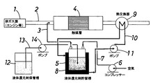
- FIG. 1 is a flow sheet showing a first embodiment of an exhaust gas purification system according to the first invention of the present invention.
- a first invention of the present invention is a reducing agent supply pipe (reducing agent supply means) in order from an upstream side to an exhaust passage 2 from an exhaust gas source 1 such as an internal combustion engine such as a marine diesel engine. 3 and a denitration catalyst layer 4 are disposed, a reducing agent is added to the catalyst layer 4 from the reducing agent supply pipe 3, and nitrogen oxides in the exhaust gas are reduced, whereby the exhaust gas is purified.
- the liquid reducing agent storage tank 5 for storing the liquid reducing agent and a compressor (compressed air supply means) 6 are provided, and the compressor is used for the reducing agent vaporized in the liquid reducing agent storage tank 5. Compressed air is supplied (purged) from 6 to form vaporized reducing agent-entrained air, and this vaporized reducing agent-entrained air is supplied to the reducing agent supply pipe 3.
- the compounds that can be used as the liquid reducing agent include alcohols such as methanol, ethanol, and propanol, ethers such as diethyl ether, ketones such as methyl ethyl ketone, and hydrocarbons such as light oil, kerosene, and gasoline. It is preferably at least one low molecular weight organic compound selected from the group.
- a denitration catalyst whose active ingredient is zeolite as the denitration catalyst in the denitration catalyst system using the liquid reducing agent.
- the temperature of the liquid reducing agent storage tank 5 it is preferable to keep the temperature of the liquid reducing agent storage tank 5 constant in order to make the concentration of the vaporizing reducing agent in the vaporized reducing agent accompanying air constant.
- a jacket type heater (heating means) 8 is provided on the peripheral wall of the liquid reducing agent storage tank 5, and the temperature of the liquid reducing agent in the storage tank 5 is adjusted by the heater 8.
- a circulating heat medium heating heat exchanger 9 is installed in the exhaust passage 2 downstream of the denitration catalyst layer 4, and the heat exchanger 9 and the heater 8 are connected by a heat medium circulation pipe 10.
- the circulating heat medium for heating is sent from the jacket type heater 8 of the storage tank 5 to the heat exchanger 9, and this heat exchanger 9
- the circulating heat medium is heated by the exhaust heat of the purified exhaust gas discharged from the catalyst layer 4 and then returned to the jacket heater 8 of the liquid reducing agent storage tank 5 so that the temperature of the storage tank 5 is constant. It is preferred that it be retained.
- the temperature of the liquid reducing agent in the liquid reducing agent storage tank 5 is preferably maintained at 40 ° C. or higher and 60 ° C. or lower.
- the circulating heat medium is heated to, for example, 50 ° C. with the exhaust heat of the purified exhaust gas discharged from the catalyst layer 4. Then, it is preferable to return to the jacket type heater 8 of the storage tank 5 by the heat medium circulation pipe 10 and keep the temperature of the storage tank 5 at 50 ° C.
- the circulating heat medium heating heat exchanger 9 is installed in the exhaust passage 2 on the downstream side of the denitration catalyst layer 4, and the exhaust heat of the purified exhaust gas discharged from the denitration catalyst layer 4 is used to generate liquid.
- the temperature of the reducing agent storage tank 5 is kept constant.
- water is usually used as the circulating heat medium, but other low molecular hydrocarbons such as pentane, isopentane, butane, and propane, and Freon (R134a, R245fa) can also be used.
- An optimum circulating heat medium is selected according to the temperature distribution of the exhaust heat to be recovered.
- the exhaust gas purification system of the first invention of the present invention by controlling the flow rate of compressed air supplied from the compressor 6 via the conduit 7 into the upper space of the liquid reducing agent storage tank 5 and the liquid reducing agent temperature in the storage tank, It is preferable to control the amount of the vaporizing and reducing agent added to the exhaust gas.
- the vapor pressure of the vaporizing reducing agent in the upper space of the storage tank 5 is kept constant, and stored.
- the concentration of the vaporization reducing agent in the upper space of the tank 5 is constant. Therefore, by controlling the flow rate of the compressed air supplied into the upper space of the storage tank 5 and the liquid reducing agent temperature in the storage tank, the amount of the vaporizing and reducing agent accompanying the compressed air is also controlled.
- the exhaust gas purification system of the first invention of the present invention further includes a liquid reducing agent storage tank 12, and a liquid level gauge (not shown) is installed in the liquid reducing agent storage tank 5.
- a liquid level gauge (not shown) is installed in the liquid reducing agent storage tank 5.
- the liquid reducing agent storage tank 12 Based on the level detection signal of the upper surface (liquid level) of the liquid reducing agent in the storage tank 5 from the liquid level gauge, when the reducing agent liquid level falls below the storage lower limit value, the liquid reducing agent storage tank 12
- the liquid reducing agent storage tank 12 When the liquid reducing agent is replenished via the conduit 13 by the operation of the pump 14 and the reductant liquid level exceeds the storage upper limit value, the operation of the pump 14 is stopped and the replenishment of the liquid reducing agent is stopped. It is preferable to control the supply amount of the reducing agent supplied to the liquid reducing agent storage tank 5.
- the exhaust gas temperature is a relatively low temperature exhaust gas having an exhaust gas temperature of about 200 to 400 ° C., such as exhaust gas from an internal combustion engine such as a marine diesel engine.
- a pre-vaporized reducing agent when it is added to the exhaust gas, thus suppressing a decrease in exhaust gas temperature due to the heat of vaporization of the liquid reducing agent and maintaining high denitration performance. can do.
- the amount of vaporization reducing agent accompanying the compressed air can be controlled.
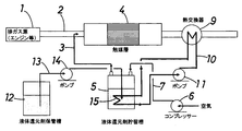
- FIG. 2 is a flow sheet showing a second embodiment of the exhaust gas purification system according to the first invention of the present invention.
- an internal heater (heating means) 15 is provided in the liquid reducing agent storage tank 5, and the liquid in the storage tank 5 is provided by the internal heater 15.
- the temperature of the reducing agent is adjusted.
- a circulating heat medium heating heat exchanger 9 is installed in the exhaust passage 2 downstream of the denitration catalyst layer 4, and the heat exchanger 9 and the internal heater 15 are connected by the heat medium circulation pipe 10.
- the circulating heat medium for heating is sent from the internal heater 15 of the storage tank 5 to the heat exchanger 9, and this heat exchanger 9
- the circulating heat medium is heated by the exhaust heat of the purified exhaust gas discharged from the catalyst layer 4 and then returned to the internal heater 15 of the liquid reducing agent storage tank 5 to keep the temperature of the storage tank 5 constant.
- ethanol used as the liquid reducing agent
- it is circulated by the exhaust heat of the purified exhaust gas discharged from the catalyst layer 4.
- After heating the heat medium to, for example, 50 ° C. it is preferable to return the heat medium to the internal heater 15 of the storage tank 5 by the heat medium circulation pipe 10 and keep the temperature of the storage tank 5 at 50 ° C.
- the flow rate of compressed air supplied from the compressor 6 to the upper space of the liquid reducing agent storage tank 5 through the conduit 7 and the liquid reducing agent temperature in the storage tank are controlled. Therefore, in order to control the amount of the vaporizing / reducing agent added to the exhaust gas, or to keep the vaporizing / reducing agent concentration in the air accompanying the vaporizing / reducing agent constant, a liquid level gauge (level switch) ( (Not shown) is installed and the storage level of the liquid reducing agent in the storage tank 5 is kept constant, as in the case of the first embodiment of the first invention.
- level switch level switch
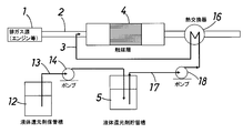
- FIG. 3 is a flow sheet showing the first embodiment of the exhaust gas purification system according to the second invention of the present invention.
- a second invention of the present invention is a reducing agent supply pipe (reducing agent supply means) in order from the upstream side to an exhaust passage 2 from an exhaust gas source 1 such as an internal combustion engine such as a marine diesel engine. ) 3 and a denitration catalyst layer 4 are disposed, a reducing agent is added to the catalyst layer 4 from the reducing agent supply pipe 3, and nitrogen oxides in the exhaust gas are reduced, whereby the exhaust gas is purified.
- the liquid reducing agent storage tank 5 for storing the liquid reducing agent and the heat exchanger 16 for vaporizing the reducing agent are provided.
- the liquid reducing agent storage tank 5 is led out through the conduit 17 by the operation of the pump 18.
- the reduced reducing agent heated in the heat exchanger 16 is vaporized, and the vaporized reducing agent is supplied to the reducing agent supply pipe 3.
- the reducing agent vaporization heat exchanger 16 is installed in the exhaust passage 2 on the downstream side of the denitration catalyst layer 4, and the purified exhaust gas discharged from the catalyst layer 4 in the heat exchanger 16. It is preferable that the liquid reducing agent is heated and vaporized by the exhaust heat.
- the compound that can be used as the liquid reducing agent is the group consisting of alcohols, ethers, ketones, and hydrocarbons, as in the first invention. It is at least one organic compound having a low molecular weight selected from among them.
- the reducing agent made of ethanol is heated to the boiling point or higher by the exhaust heat of the exhaust gas and vaporized, and this vaporized reducing agent is supplied into the exhaust passage 2 from the reducing agent supply pipe 3.
- the amount of vaporized reducing agent added to the exhaust gas is controlled by controlling the amount of liquid reducing agent derived from the liquid reducing agent storage tank 5 by the operation of the pump 18. It is preferable to do.
- a liquid reducing agent storage tank 12 is further provided, and the liquid reducing agent is stored in the liquid reducing agent storage tank 5 via the conduit 13 by the operation of the pump 14 from the liquid reducing agent storage tank 12. It is made to replenish.
- the liquid reducing agent storage tank 5 is led to the vaporization heat exchanger 16 through the conduit 17 by the operation of the pump 18.
- the derived amounts of both pumps 14 and 18 are set so that the same amount of liquid reducing agent is replenished to the liquid reducing agent storage tank 5 by the operation of the pump 14 from the liquid reducing agent storage tank 12. It is preferable to control.
- the exhaust gas purification system of the second invention of the present invention even if the exhaust gas temperature is a relatively low temperature exhaust gas having an exhaust gas temperature of about 200 to 400 ° C., such as exhaust gas from an internal combustion engine such as a marine diesel engine, alcohol
- a liquid reducing agent such as hydrocarbon
- a reducing agent vaporized in advance can be supplied, so that a reduction in the exhaust gas temperature due to the heat of vaporization of the liquid reducing agent is suppressed and high. Denitration performance can be maintained.
- the amount of the liquid reducing agent derived from the liquid reducing agent storage tank 5 by the operation of the pump 18, it is easy to control the amount of the vaporizing reducing agent added to the exhaust gas, and the practicality is excellent. It is what.
- Example 1 The exhaust gas purification system of the present invention was implemented based on FIG. 1 showing the flow sheet of the first embodiment of the first invention of the present invention.
- a reducing agent supply pipe (reducing agent supply means) is sequentially supplied from an upstream side to an exhaust passage 2 from an exhaust gas source 1 such as an internal combustion engine such as a marine diesel engine. 3 and a denitration catalyst layer 4 are disposed, and the exhaust gas purification system further includes a liquid reducing agent storage tank 5 for storing the liquid reducing agent and a compressor (compressed air supply means) 6.
- the synthesis gas containing 600 [ppmvd] of sulfur oxide (SOx) was used and supplied to the exhaust passage 2 at a temperature of 250 [° C.].
- the denitration catalyst layer 4 was filled with a corrugated honeycomb structure type denitration catalyst on which zeolite ion-exchanged cobalt was supported.
- ethanol CH 3 CH 2 OH: boiling point 78.37 ° C., 5000 [ppmvd]
- the circulating water heating heat exchanger 9 installed in the exhaust passage 2 downstream of the denitration catalyst layer 4, the circulating water is heated to, for example, 50 ° C. with the exhaust heat of the purified exhaust gas discharged from the catalyst layer 4. After that, it was returned to the jacket type heater 8 of the liquid ethanol storage tank 5 by the hot water circulation pipe 10, and the temperature of the storage tank 5 was kept at 50 ° C.
- the area velocity is the amount of processing gas per gas contact area of the honeycomb type denitration catalyst, and is represented by the following equation.
- Area velocity treatment gas amount (Nm 3 / h) / gas contact area (m 2 )
- the temperature of the liquid ethanol in the storage tank 5 at 50 ° C.
- the vapor pressure of the vaporization reducing agent in the upper space of the storage tank 5 is kept constant, and the vaporization reduction in the upper space of the storage tank 5 is performed.
- the concentration of the agent became constant.
- the amount of the vaporizing reducing agent accompanying the compressed air is also controlled.
- the amount of the vaporized reducing agent added to the exhaust gas could be controlled.
- the temperature of the vaporized ethanol-entrained air when the vaporized ethanol-entrained air is supplied from the reducing agent supply pipe 3 into the exhaust passage 2 is about 50 ° C., but the ethanol vaporized in advance is added to the exhaust gas. Therefore, the reduction of the exhaust gas temperature due to the heat of vaporization of liquid ethanol can be suppressed, and the exhaust gas temperature at the inlet of the denitration catalyst layer 4 remains about 250 ° C. High denitration performance by the catalyst of the catalyst layer 4 could be maintained.
- Table 1 shows the temperature of the exhaust gas introduced from the exhaust gas source 1 into the exhaust passage 2 and the exhaust gas temperature at the inlet of the denitration catalyst layer after the vaporized ethanol-entrained air is supplied from the reducing agent supply pipe 3 into the exhaust passage 2. It was.
- the exhaust gas purification system is further provided with a liquid ethanol storage tank 12, and a liquid level gauge (level switch) is installed in the liquid ethanol storage tank 5, so that the liquid ethanol in the storage tank 5 from the liquid level gauge Based on the level detection signal of the upper surface (liquid level), when the ethanol liquid level falls below the storage lower limit value, liquid ethanol is replenished from the liquid ethanol storage tank 12 through the conduit 13 by the operation of the pump 14, and the ethanol liquid level When the level exceeded the upper storage limit, the pump 14 was stopped and the supply of liquid ethanol was stopped, thereby controlling the amount of ethanol supplied to the liquid ethanol storage tank 5.
- a liquid level gauge level switch
- Example 2 The exhaust gas purification system of the present invention is implemented in the same manner as in the case of the first example, but the difference from the case of the first example is the flow sheet of the second embodiment of the first invention of the present invention.
- the exhaust gas purification system is implemented based on FIG. That is, a heater (heating means) 15 was provided inside the liquid reducing agent storage tank 5, and the temperature of the liquid reducing agent in the storage tank 5 was adjusted by the internal heater 15.
- ethanol is used as the liquid reducing agent
- the heat exchanger 9 installed in the exhaust passage 2 on the downstream side of the denitration catalyst layer 4, the circulating water is discharged by the exhaust heat of the purified exhaust gas discharged from the catalyst layer 4.
- Table 1 shows the temperature of the exhaust gas introduced from the exhaust gas source 1 into the exhaust passage 2 and the reducing agent supply pipe 3.
- the exhaust gas temperature at the inlet of the denitration catalyst layer after supplying vaporized ethanol-entrained air into the exhaust passage 2 is also shown.
- Example 3 The exhaust gas purification system of the present invention is implemented in the same manner as in the case of the first example, but the difference from the case of the first example is the flow sheet of the first embodiment of the second invention of the present invention.
- the exhaust gas purification system is implemented based on FIG.
- a reducing agent supply pipe (reducing agent supply means) 3 and a denitration catalyst layer 4 are disposed in the exhaust passage 2 from the exhaust gas source 1 in order from the upstream side.
- the exhaust gas purification system includes a liquid reducing agent storage tank 5 for storing a liquid reducing agent and a heat exchanger 16 for reducing agent vaporization, and a conduit 17 is operated from the liquid reducing agent storage tank 5 by operating a pump 18.
- the reducing agent derived through the above is heated and vaporized in the heat exchanger 16, and this vaporized reducing agent is supplied to the reducing agent supply pipe 3.
- a reducing agent vaporizing heat exchanger 16 is installed in the exhaust passage 2 downstream of the denitration catalyst layer 4, and the exhaust heat of the purified exhaust gas discharged from the catalyst layer 4 in the heat exchanger 16.
- the liquid reducing agent is heated and vaporized.
- ethanol (boiling point 78.37 ° C.) is used as the liquid reducing agent, and the catalyst layer is installed in the heat exchanger 16 installed in the exhaust passage 2 downstream of the denitration catalyst layer 4.
- the liquid reducing agent made of ethanol was heated to 120 ° C. by the exhaust heat of the purified exhaust gas discharged from 4 and vaporized, and this vaporized reducing agent was supplied into the exhaust passage 2 from the reducing agent supply pipe 3.
- the temperature of vaporized ethanol when the vaporized ethanol is supplied from the reducing agent supply pipe 3 into the exhaust passage 2 is about 120 ° C., but when added to the exhaust gas, the reducing agent is made of ethanol vaporized in advance. Therefore, the decrease in exhaust gas temperature due to the heat of vaporization of liquid ethanol can be suppressed, and the exhaust gas temperature at the inlet of the denitration catalyst layer 4 does not change from about 250 ° C., thereby achieving high denitration performance.
- the exhaust gas temperature at the inlet of the denitration catalyst layer 4 does not change from about 250 ° C., thereby achieving high denitration performance.
- Table 1 shows the temperature of the exhaust gas introduced from the exhaust gas source 1 into the exhaust passage 2 and the exhaust gas temperature at the denitration catalyst layer inlet after the vaporized ethanol is supplied into the exhaust passage 2 from the reducing agent supply pipe 3. It was.
- the same amount is obtained from the liquid ethanol storage tank 12 by the operation of the pump 14 corresponding to the amount of liquid ethanol derived from the liquid ethanol storage tank 5 through the conduit 17 to the vaporizing heat exchanger 16 by the operation of the pump 18.
- the amount of liquid ethanol stored in the liquid ethanol storage tank 5 was maintained by controlling the amount of the pumps 14 and 18 to be replenished to the storage tank 5.
- a reducing agent supply pipe (reducing agent supply means) 23 and a denitration catalyst layer 24 are arranged in the exhaust passage 22 from the exhaust gas source 21 in order from the upstream side.
- the purification system includes a liquid reducing agent storage tank 25 for storing the liquid reducing agent, and the reducing agent derived from the liquid reducing agent storage tank 25 by the operation of the pump 26 is supplied from the supply pipe 23 to the exhaust passage 22. It was directly introduced into the interior and vaporized in the exhaust gas.
- the liquid reducing agent ethanol (boiling point 78.37 ° C.) was used as in the case of Example 1 above.
- the exhaust gas temperature decreased due to the vaporization heat of liquid ethanol, and the exhaust gas temperature at the inlet of the denitration catalyst layer 24 decreased to 243 ° C.
- the temperature of the denitration reaction of the denitration catalyst layer 24 is lowered, and it is considered that the denitration performance of the catalyst layer 24 is lowered.
- Table 1 below shows the temperature of the exhaust gas introduced from the exhaust gas source 21 into the exhaust passage 22 and the exhaust gas temperature at the inlet of the denitration catalyst layer 24 after liquid ethanol is directly supplied into the exhaust passage 2 from the reducing agent supply pipe 23. Showed.
- the exhaust gas purification system of Comparative Example 1 further includes a liquid reducing agent storage tank 27, and liquid ethanol is replenished to the liquid ethanol storage tank 25 from the liquid reducing agent storage tank 27 through the conduit 28 by the operation of the pump 29. I tried to do it.
- a reducing agent made of ethanol is directly introduced into the exhaust passage 22 upstream of the denitration catalyst layer 24 in a liquid state, and the period from the introduction to the denitration catalyst layer 24 is reached. Since the reducing agent made of ethanol is vaporized, the temperature of the exhaust gas is lowered due to the heat of vaporization of the reducing agent, resulting in a problem that the denitration performance of the catalyst in the denitration catalyst layer 4 is lowered.
Landscapes
- Chemical & Material Sciences (AREA)
- Engineering & Computer Science (AREA)
- Chemical Kinetics & Catalysis (AREA)
- Health & Medical Sciences (AREA)
- Toxicology (AREA)
- Combustion & Propulsion (AREA)
- Mechanical Engineering (AREA)
- General Engineering & Computer Science (AREA)
- Exhaust Gas After Treatment (AREA)
- Exhaust Gas Treatment By Means Of Catalyst (AREA)
Abstract
【課題】 例えば船舶用ディーゼルエンジン等の内燃機関の排ガスのように、排ガス温度が200~400℃程度の比較的低温域の排ガスであっても、アルコール、炭化水素などの液体還元剤を添加して、排ガス中の窒素酸化物(NOx)を除去することができて、しかも排ガス温度を低下させることなく、高い脱硝性能を維持することができ、実用性に優れている、排ガス浄化システムを提供する。 【解決手段】 排ガス浄化システムは、内燃機関の排気通路に、上流側から順に還元剤供給手段と脱硝触媒層が配置され、前記還元剤供給手段より還元剤が前記触媒層上流側の排ガスに添加され、排ガス中の窒素酸化物が還元されて、排ガスが浄化されるものであり、液体還元剤貯留槽と、圧縮空気供給手段とを備えており、前記液体還元剤貯留槽内で気化した還元剤に対して前記圧縮空気供給手段から圧縮空気が供給されて、気化還元剤同伴空気が形成され、この気化還元剤同伴空気が前記還元剤供給手段に供給されることを特徴としている。
Description
本発明は、例えば船舶用ディーゼルエンジン等の内燃機関などの排ガスの浄化システム、さらに詳しくは、内燃機関などの排ガスに、アルコール、炭化水素などの液体還元剤を添加して、排ガス中の窒素酸化物(NOx)を除去する排ガス浄化システムに関するものである。
一般に、船舶用ディーゼルエンジン等の内燃機関などの排ガス中の窒素酸化物の除去方法としては、例えば下記の特許文献1に記載のように、排ガスにアンモニア系還元剤を添加し、脱硝触媒に接触させる方法が知られており、そしてこの場合、アンモニア系還元剤の添加方法は、脱硝触媒層の上流側の排気通路に、アンモニア系還元剤を液体の状態でスプレー等により噴霧し、脱硝触媒層に到達する前にアンモニア系還元剤を気化させる方法が採用されている。
一方、例えば下記の特許文献2に記載のように、船舶用ディーゼルエンジン等の内燃機関などの排ガス温度が300~400℃程度の比較的低温域での排ガスの浄化方法として、排ガス中に、アンモニア系還元剤以外のアルコール、炭化水素などの還元剤を添加して、排ガス中の窒素酸化物を除去する方法についても、検討が進められている。
しかしながら、上記特許文献2に記載の従来の排ガス浄化システムでは、脱硝触媒層の上流側の排気通路に、アルコール系還元剤を液体の状態でスプレー等により噴霧し、脱硝触媒層に到達する前にアルコール系還元剤を気化させているため、還元剤の気化熱により排ガス温度が低下し、触媒層における触媒の脱硝性能が低下するという問題があった。そして、これに対処するためには、例えば脱硝触媒の使用量を増加するなどの対策が必要であるという問題があった。特に、船舶用ディーゼルエンジン等の内燃機関などでは、排ガス温度が200~400℃程度とさらに低温域であるため、還元剤の気化熱により排ガス温度がさらに低くなると、十分な脱硝性能が得られず、実用化が難しいというのが現状であった。
本発明の目的は、上記の従来技術の問題を解決し、例えば船舶用ディーゼルエンジン等の内燃機関の排ガスのように、排ガス温度が200~400℃程度の比較的低温域の排ガスであっても、アルコール、炭化水素などの液体還元剤を用いて、しかも排ガス温度を低下させることなく、高い脱硝性能を維持することができて、実用性に優れている、排ガス浄化システムを提供することにある。
本発明者らは、上記の点に鑑み鋭意研究を重ねた結果、液体還元剤貯留槽内で気化した還元剤に対して圧縮空気を供給し、これにより形成された気化還元剤同伴空気を内燃機関の脱硝触媒層上流側の排気通路に供給することにより、排ガスに添加する際に、事前に気化した還元剤を供給することができて、従来の液体還元剤の気化熱による排ガス温度の低下を抑制し、高い脱硝性能を維持することができて、実用性に優れた排ガス浄化システムを構築できることを見出し、本発明を完成するに至ったものである。
また、本発明者らは、液体還元剤貯留槽からの還元剤を熱交換器において加熱して気化させ、この気化還元剤を内燃機関の脱硝触媒層上流側の排気通路に供給することにより、排ガスに添加する際に、事前に気化した還元剤を供給することができて、従来の液体還元剤の気化熱による排ガス温度の低下を抑制し、高い脱硝性能を維持することができて、実用性に優れた排ガス浄化システムを構築できることを見出し、本発明を完成するに至ったものである。
上記の目的を達成するために、請求項1の発明は、内燃機関の排気通路に、上流側から順に還元剤供給手段と脱硝触媒層が配置され、前記還元剤供給手段より還元剤が前記触媒層上流側の排ガスに添加され、排ガス中の窒素酸化物が還元されて、排ガスが浄化される排ガス浄化システムにおいて、液体還元剤貯留槽と、圧縮空気供給手段とを備えており、前記液体還元剤貯留槽内で気化した還元剤に対して前記圧縮空気供給手段から圧縮空気が供給されて、気化還元剤同伴空気が形成され、この気化還元剤同伴空気が前記還元剤供給手段に供給されることを特徴としている。
請求項2の発明は、請求項1に記載の排ガス浄化システムであって、前記圧縮空気供給手段から液体還元剤貯留槽内に供給する圧縮空気の流量および貯留槽内液体還元剤温度を制御することにより、排ガスに添加する気化還元剤量を制御することを特徴としている。
請求項3の発明は、請求項1または2に記載の排ガス浄化システムであって、さらに液体還元剤保管槽を備えており、前記液体還元剤貯留槽には液面計が設置され、この液面計からの貯留槽内還元剤液上面のレベル検知信号に基づいて、前記液体還元剤保管槽から液体還元剤貯留槽に供給される還元剤の供給量が制御されることを特徴としている。
請求項4の発明は、請求項1~3のうちのいずれか一項に記載の排ガス浄化システムであって、前記液体還元剤貯留槽に加熱手段が備えられ、この加熱手段によって貯留槽内の液体還元剤の温度が調整されることを特徴としている。
請求項5の発明は、請求項4に記載の排ガス浄化システムであって、脱硝触媒層の下流側の排気通路に循環熱媒体加熱用熱交換器が設置され、該熱交換器と前記加熱手段とは熱媒体循環管によって接続されており、該熱交換器において触媒層から排出された浄化排ガスの排熱で、液体還元剤貯留槽の加熱手段からの循環熱媒体が加温されることを特徴としている。
請求項6の発明は、内燃機関の排気通路に、上流側から順に還元剤供給手段と脱硝触媒層が配置され、前記還元剤供給手段より還元剤が前記触媒層上流側の排ガスに添加され、排ガス中の窒素酸化物が還元されて、排ガスが浄化される排ガス浄化システムにおいて、液体還元剤貯留槽と、還元剤気化用熱交換器とを備えており、液体還元剤貯留槽から導出された還元剤が熱交換器において加熱されて気化せしめられ、この気化還元剤が、前記還元剤供給手段に供給されることを特徴としている。
請求項7の発明は、請求項6に記載の排ガス浄化システムであって、還元剤気化用熱交換器が、脱硝触媒層の下流側の排気通路に設置され、該熱交換器において触媒層から排出された浄化排ガスの排熱で液体還元剤が加熱されて気化せしめられることを特徴としている。
請求項8の発明は、請求項1~7のうちのいずれか一項に記載の排ガス浄化システムであって、液体還元剤が、アルコール、エーテル、ケトン類、および炭化水素よりなる群の中から選ばれた少なくとも1つの有機化合物であることを特徴としている。
本発明によれば、例えば船舶用ディーゼルエンジン等の内燃機関の排ガスのように、排ガス温度が200~400℃程度の比較的低温域の排ガスであっても、アルコール、炭化水素などの液体還元剤を用いて、しかも排ガスに添加する際に、事前に気化した還元剤を供給することができて、従来の液体還元剤の気化熱による排ガス温度の低下を抑制し、高い脱硝性能を維持することができるうえに、気化還元剤の添加量の制御が容易であり、実用性に優れているという効果を奏する。
1:内燃機関などの排ガス源
2:排気通路
3:還元剤供給用管(還元剤供給手段)
4:脱硝触媒層
5:液体還元剤貯留槽
6:コンプレッサー(圧縮空気供給手段)
7:導管
8:ジャケット式加熱器(加熱手段)
9:循環水加熱用熱交換器(循環熱媒体加熱用熱交換器)
10:温水循環管(熱媒体循環管)
11:ポンプ
12:液体還元剤保管槽
13:導管
14:ポンプ
15:内部加熱器(加熱手段)
16:還元剤気化用熱交換器
17:導管
18:ポンプ
2:排気通路
3:還元剤供給用管(還元剤供給手段)
4:脱硝触媒層
5:液体還元剤貯留槽
6:コンプレッサー(圧縮空気供給手段)
7:導管
8:ジャケット式加熱器(加熱手段)
9:循環水加熱用熱交換器(循環熱媒体加熱用熱交換器)
10:温水循環管(熱媒体循環管)
11:ポンプ
12:液体還元剤保管槽
13:導管
14:ポンプ
15:内部加熱器(加熱手段)
16:還元剤気化用熱交換器
17:導管
18:ポンプ
つぎに、本発明の実施の形態を、図面を参照して説明するが、本発明はこれらに限定されるものではない。
図1は、本発明の第1発明による排ガス浄化システムの第1実施形態を示すフローシートである。
同図を参照すると、本発明の第1発明は、例えば船舶用ディーゼルエンジン等の内燃機関などの排ガス源1からの排気通路2に、上流側から順に還元剤供給用管(還元剤供給手段)3と脱硝触媒層4が配置され、前記還元剤供給用管3より還元剤が前記触媒層4に添加され、排ガス中の窒素酸化物が還元されて、排ガスが浄化される排ガス浄化システムであって、液体還元剤を貯留させるための液体還元剤貯留槽5と、コンプレッサー(圧縮空気供給手段)6とを備えており、前記液体還元剤貯留槽5内で気化した還元剤に対して前記コンプレッサー6から圧縮空気が供給(パージ)されて、気化還元剤同伴空気が形成され、この気化還元剤同伴空気が前記還元剤供給管3に供給されることを特徴としている。
この実施形態においては、液体還元剤貯留槽5上部の空間内に、コンプレッサー6から導管7を経て圧縮空気を供給(パージ)することで、気化還元剤同伴空気を形成し、この気化還元剤同伴空気を前記還元剤供給管3より排気通路2内に供給する。
ここで、液体還元剤として用いることができる化合物としては、メタノール、エタノール、プロパノール等のアルコール類、ジエチルエーテル等のエーテル類、メチルエチルケトン等のケトン類、および軽油、灯油、ガソリン等の炭化水素よりなる群の中から選ばれた少なくとも1つの低分子量の有機化合物であることが好ましい。
また、例えば船舶用ディーゼルエンジン等の内燃機関の排ガスなどの浄化処理にあたり、上記液体還元剤を用いた脱硝触媒システムにおける脱硝触媒としては、有効成分がゼオライトである脱硝触媒を使用するのが好ましい。
そして、本発明の第1発明において、気化還元剤同伴空気中の気化還元剤濃度を一定にするために、液体還元剤貯留槽5の温度を一定に保つことが好ましい。
この実施形態においては、液体還元剤貯留槽5の周壁にジャケット式加熱器(加熱手段)8が設けられ、この加熱器8によって貯留槽5内の液体還元剤の温度が調整される。そしてこの場合、脱硝触媒層4の下流側の排気通路2に循環熱媒体加熱用熱交換器9が設置され、該熱交換器9と上記加熱器8とは熱媒体循環管10によって接続されており、熱媒体循環管10の途上に介在させられたポンプ11の作動によって、貯留槽5のジャケット式加熱器8から加熱用循環熱媒体が熱交換器9に送り込まれ、この熱交換器9おいて循環熱媒体が、触媒層4から排出された浄化排ガスの排熱で加温された後、液体還元剤貯留槽5のジャケット式加熱器8に返送されて、貯留槽5の温度が一定に保持されることが好ましい。
ここで、液体還元剤として、例えばエタノール(沸点78.37℃)を使用した場合、液体還元剤貯留槽5の液体還元剤の温度を、40℃以上、60℃以下に保持することが好ましい。このとき、例えば脱硝触媒層4の下流側の排気通路2に設置された熱交換器9において、触媒層4から排出された浄化排ガスの排熱で循環熱媒体を、例えば50℃に加温した後、熱媒体循環管10によって貯留槽5のジャケット式加熱器8に返送し、貯留槽5の温度を50℃に保持することが好ましい。
上記のように、脱硝触媒層4の下流側の排気通路2に循環熱媒体加熱用熱交換器9が設置されて、脱硝触媒層4から排出された浄化排ガスの排熱を利用して、液体還元剤貯留槽5の温度が一定に保持されている。ここで、循環熱媒体としては、通常、水を使用するが、その他、ペンタン、イソペンタン、ブタン、プロパン等の低分子炭化水素、およびフロン(R134a、R245fa)等を用いることができる。循環熱媒体は、回収する排熱の温度分布に応じて最適なものが選定される。
本発明の第1発明の排ガス浄化システムにおいて、コンプレッサー6から導管7を経て液体還元剤貯留槽5の上部空間内に供給する圧縮空気の流量および貯留槽内液体還元剤温度を制御することにより、排ガスに添加する気化還元剤量を制御することが好ましい。
上記のように、貯留槽5内の液体還元剤の温度を所定温度(例えば50℃)に保持することにより、貯留槽5の上部空間内の気化還元剤の蒸気圧は一定に保持され、貯留槽5の上部空間内の気化還元剤の濃度が一定となる。従って、貯留槽5の上部空間内に供給する圧縮空気の流量および貯留槽内液体還元剤温度を制御することにより、圧縮空気に同伴される気化還元剤の量も制御され、この気化還元剤同伴空気を還元剤供給管3から排気通路2内の排ガスに添加することにより、排ガスへの気化還元剤の添加量を制御することが可能となる。
また、気化還元剤同伴空気中の気化還元剤濃度を一定にするために、液体還元剤貯留槽5内の液体還元剤の貯留量を一定に保つことが好ましい。
すなわち、本発明の第1発明の排ガス浄化システムにおいて、さらに液体還元剤保管槽12を備えており、前記液体還元剤貯留槽5には液面計(レベルスイッチ)(図示略)が設置され、この液面計からの貯留槽5内の液体還元剤の上面(液面)のレベル検知信号に基づいて、還元剤液面レベルが貯留下限値を下回った際に、液体還元剤保管槽12からポンプ14の作動により導管13を経て液体還元剤を補充し、還元剤液面レベルが貯留上限値を上回った際に、ポンプ14の作動を止めて、液体還元剤の補充を停止することにより、液体還元剤貯留槽5に供給される還元剤の供給量を制御することが好ましい。
本発明の第1発明によれば、例えば船舶用ディーゼルエンジン等の内燃機関の排ガスのように、排ガス温度が200~400℃程度の比較的低温域の排ガスであっても、アルコール、炭化水素などの液体還元剤を用いて、しかも排ガスに添加する際に、事前に気化した還元剤を供給することができるため、液体還元剤の気化熱による排ガス温度の低下を抑制し、高い脱硝性能を維持することができる。そのうえ、液体還元剤貯留槽5の上部空間内に供給する圧縮空気の流量および貯留槽内液体還元剤温度を制御することにより、圧縮空気に同伴される気化還元剤の量を制御することができ、この気化還元剤同伴空気を還元剤供給管3から排気通路2内の排ガスに添加することにより、排ガスへの気化還元剤の添加量の制御が容易であり、実用性に優れているものである。
図2は、本発明の第1発明による排ガス浄化システムの第2実施形態を示すフローシートである。
ここで、上記第1発明の第1実施形態の場合と異なる点は、液体還元剤貯留槽5に内部加熱器(加熱手段)15が設けられ、この内部加熱器15によって貯留槽5内の液体還元剤の温度が調整される点にある。そしてこの場合、脱硝触媒層4の下流側の排気通路2に循環熱媒体加熱用熱交換器9が設置され、該熱交換器9と上記内部加熱器15とは熱媒体循環管10によって接続されており、熱媒体循環管10の途上に介在させられたポンプ11の作動によって、貯留槽5の内部加熱器15から加熱用循環熱媒体が熱交換器9に送り込まれ、この熱交換器9おいて循環熱媒体が、触媒層4から排出された浄化排ガスの排熱で加温された後、液体還元剤貯留槽5の内部加熱器15に返送されて、貯留槽5の温度が一定に保持されることが好ましい。このとき、例えば液体還元剤としてエタノールを使用した場合、例えば脱硝触媒層4の下流側の排気通路2に設置された熱交換器9において、触媒層4から排出された浄化排ガスの排熱で循環熱媒体を、例えば50℃に加温した後、熱媒体循環管10によって貯留槽5の内部加熱器15に返送し、貯留槽5の温度を50℃に保持することが好ましい。
なお、第1発明の第2実施形態の排ガス浄化システムにおいて、コンプレッサー6から導管7を経て液体還元剤貯留槽5の上部空間内に供給する圧縮空気の流量および貯留槽内液体還元剤温度を制御することにより、排ガスに添加する気化還元剤量を制御したり、気化還元剤同伴空気中の気化還元剤濃度を一定にするために、液体還元剤貯留槽5に液面計(レベルスイッチ)(図示略)を設置して、貯留槽5中の液体還元剤の貯留レベルを一定に保持するなど点は、上記第1発明の第1実施形態の場合と同様である。
この第1発明の第2実施形態において、その他の点は、上記第1発明の第1実施形態の場合と同様であるので、図2において、上記図1と同一のものには、同一の符号を付した。
図3は、本発明の第2発明による排ガス浄化システムの第1実施形態を示すフローシートである。
同図を参照すると、本発明の第2の発明は、例えば船舶用ディーゼルエンジン等の内燃機関などの排ガス源1からの排気通路2に、上流側から順に還元剤供給用管(還元剤供給手段)3と脱硝触媒層4が配置され、前記還元剤供給用管3より還元剤が前記触媒層4に添加され、排ガス中の窒素酸化物が還元されて、排ガスが浄化される排ガス浄化システムであって、液体還元剤を貯留させるための液体還元剤貯留槽5と、還元剤気化用熱交換器16とを備えており、液体還元剤貯留槽5からポンプ18の作動により導管17を経て導出された還元剤が熱交換器16において加熱されて気化せしめられ、この気化還元剤が、前記還元剤供給管3に供給されることを特徴としている。
この第2発明の排ガス浄化システムにおいて、還元剤気化用熱交換器16が、脱硝触媒層4の下流側の排気通路2に設置され、該熱交換器16において触媒層4から排出された浄化排ガスの排熱で液体還元剤が加熱されて気化せしめられることが好ましい。
本発明の第2本発明の排ガス浄化システムにおいて、液体還元剤として用いることができる化合物は、上記第1発明の場合と同様に、アルコール類、エーテル類、ケトン類、および炭化水素よりなる群の中から選ばれた少なくとも1つの低分子量の有機化合物である。
ここで、液体還元剤として、例えばエタノール(沸点78.37℃)を使用した場合、脱硝触媒層4の下流側の排気通路2に設置された熱交換器16において触媒層4から排出された浄化排ガスの排熱でエタノールよりなる還元剤が沸点以上に加熱されて気化せしめられ、この気化還元剤が、還元剤供給管3より排気通路2内に供給されるものである。
本発明の第2発明の排ガス浄化システムにおいては、液体還元剤貯留槽5からポンプ18の作動により導出される液体還元剤の導出量を制御することにより、排ガスに添加する気化還元剤量を制御することが好ましい。
本発明の第2発明の排ガス浄化システムにおいて、さらに液体還元剤保管槽12を備えており、液体還元剤保管槽12からポンプ14の作動により導管13を経て液体還元剤を液体還元剤貯留槽5に補充するようになされている。ここで、液体還元剤貯留槽5内の液体還元剤の貯留量を保持するには、例えば液体還元剤貯留槽5からポンプ18の作動により導管17を経て気化用熱交換器16に導出される還元剤の導出量に対応して、液体還元剤保管槽12からポンプ14の作動により同量の液体還元剤を液体還元剤貯留槽5に補充するように、両ポンプ14,18の導出量を制御することが好ましい。
本発明の第2発明の排ガス浄化システムによれば、例えば船舶用ディーゼルエンジン等の内燃機関の排ガスのように、排ガス温度が200~400℃程度の比較的低温域の排ガスであっても、アルコール、炭化水素などの液体還元剤を用いて、しかも排ガスに添加する際に、事前に気化した還元剤を供給することができるため、液体還元剤の気化熱による排ガス温度の低下を抑制し、高い脱硝性能を維持することができる。そのうえ、液体還元剤貯留槽5からポンプ18の作動により導出される液体還元剤の導出量を制御することにより、排ガスへの気化還元剤の添加量の制御が容易であり、実用性に優れているものである。
つぎに、本発明の実施例を比較例と共に説明するが、本発明は、これらの実施例に限定されるものではない。
(実施例1)
本発明の第1発明の第1実施形態のフローシートを示す図1に基づいて本発明の排ガス浄化システムを実施した。
本発明の第1発明の第1実施形態のフローシートを示す図1に基づいて本発明の排ガス浄化システムを実施した。
同図を参照すると、本発明の排ガス浄化システムにおいて、例えば船舶用ディーゼルエンジン等の内燃機関などの排ガス源1からの排気通路2に、上流側から順に還元剤供給用管(還元剤供給手段)3と脱硝触媒層4が配置され、さらに排ガス浄化システムには、液体還元剤を貯留させるための液体還元剤貯留槽5と、コンプレッサー(圧縮空気供給手段)6とを備えている。
ここで、排ガスとしては、酸素(O2)を13.8〔vol%-dry〕、水(H2O)を5.0〔vol%-wet〕、窒素酸化物(NOx)を1000〔ppmvd〕、硫黄酸化物(SOx)を600〔ppmvd〕、それぞれ含有する合成ガスを使用し、250〔℃〕の温度で排気通路2に供給した。
脱硝触媒層4には、コバルトをイオン交換したゼオライトが担持されたコルゲート・ハニカム構造型脱硝触媒を充填した。
また、液体還元剤としてエタノール(CH3CH2OH:沸点78.37℃、5000〔ppmvd〕)を使用した。そして、脱硝触媒層4の下流側の排気通路2に設置された循環水加熱用熱交換器9において、触媒層4から排出された浄化排ガスの排熱で循環水を、例えば50℃に加温した後、温水循環管10によって液体エタノール貯留槽5のジャケット式加熱器8に返送し、貯留槽5の温度を50℃に保持した。
そして、液体エタノール貯留槽5上部の空間内に、コンプレッサー6から導管7を経て圧縮空気を供給(パージ)することで、気化エタノール同伴空気を形成し、この気化エタノール同伴空気を前記還元剤供給管3より排気通路2内に供給し、排ガスおよび還元剤としての気化エタノールを触媒層4の脱硝触媒に接触させて、脱硝反応による排ガスの浄化を実施した。このとき、脱硝触媒層4における面積速度を5.0(m/h)とし、反応温度を250℃とした。
ここで、面積速度は、ハニカム型脱硝触媒のガス接触面積あたりの処理ガス量であり、次式で表される。
面積速度=処理ガス量(Nm3/h)/ガス接触面積(m2)
なお、貯留槽5内の液体エタノールの温度を50℃に保持することにより、貯留槽5の上部空間内の気化還元剤の蒸気圧は一定に保持され、貯留槽5の上部空間内の気化還元剤の濃度が一定となった。このため、貯留槽5の上部空間内に供給する圧縮空気の流量および貯留槽内液体還元剤温度を制御することにより、圧縮空気に同伴される気化還元剤の量も制御され、この気化還元剤同伴空気を還元剤供給管3から排気通路2内の排ガスに添加することにより、排ガスへの気化還元剤の添加量を制御することができた。
なお、貯留槽5内の液体エタノールの温度を50℃に保持することにより、貯留槽5の上部空間内の気化還元剤の蒸気圧は一定に保持され、貯留槽5の上部空間内の気化還元剤の濃度が一定となった。このため、貯留槽5の上部空間内に供給する圧縮空気の流量および貯留槽内液体還元剤温度を制御することにより、圧縮空気に同伴される気化還元剤の量も制御され、この気化還元剤同伴空気を還元剤供給管3から排気通路2内の排ガスに添加することにより、排ガスへの気化還元剤の添加量を制御することができた。
また、気化エタノール同伴空気を前記還元剤供給管3より排気通路2内に供給する際の気化エタノール同伴空気の温度は、約50℃であるが、排ガスに添加する際に、事前に気化したエタノールよりなる還元剤を供給することができるため、液体エタノールの気化熱による排ガス温度の低下を抑制することができ、脱硝触媒層4の入口の排ガス温度は、約250℃と変わらず、これによって、触媒層4の触媒による高い脱硝性能を維持することができた。
下記の表1に、排ガス源1から排気通路2に導入した排ガスの温度と、還元剤供給管3より気化エタノール同伴空気を排気通路2内に供給した後の脱硝触媒層入口の排ガス温度を示した。
なお、この実施例においては、図示は省略したが、気化エタノール同伴空気中の気化エタノール濃度を一定にするために、貯留槽5内の液体エタノールの貯留量を一定に保持するようにした。このため、排ガス浄化システムにさらに液体エタノール保管槽12を備え、前記液体エタノール貯留槽5には液面計(レベルスイッチ)を設置して、この液面計からの貯留槽5内の液体エタノールの上面(液面)のレベル検知信号に基づき、エタノール液面レベルが貯留下限値を下回った際に、液体エタノール保管槽12からポンプ14の作動により導管13を経て液体エタノールを補充し、エタノール液面レベルが貯留上限値を上回った際に、ポンプ14の作動を止めて、液体エタノールの補充を停止することにより、液体エタノール貯留槽5に供給されるエタノールの供給量を制御するようにした。
(実施例2)
上記第1実施例の場合と同様にして、本発明の排ガス浄化システムを実施するが、第1実施例の場合と異なる点は、本発明の第1発明の第2実施形態のフローシートを示す図2に基づいて排ガス浄化システムを実施した点にある。すなわち、液体還元剤貯留槽5の内部に加熱器(加熱手段)15が設けられ、この内部加熱器15によって貯留槽5内の液体還元剤の温度を調整した。具体的には、液体還元剤としてエタノールを使用し、脱硝触媒層4の下流側の排気通路2に設置された熱交換器9において、触媒層4から排出された浄化排ガスの排熱で循環水を、50℃に加温した後、温水循環管10によって貯留槽5の内部加熱器15に返送し、貯留槽5の温度を50℃に保持した。
上記第1実施例の場合と同様にして、本発明の排ガス浄化システムを実施するが、第1実施例の場合と異なる点は、本発明の第1発明の第2実施形態のフローシートを示す図2に基づいて排ガス浄化システムを実施した点にある。すなわち、液体還元剤貯留槽5の内部に加熱器(加熱手段)15が設けられ、この内部加熱器15によって貯留槽5内の液体還元剤の温度を調整した。具体的には、液体還元剤としてエタノールを使用し、脱硝触媒層4の下流側の排気通路2に設置された熱交換器9において、触媒層4から排出された浄化排ガスの排熱で循環水を、50℃に加温した後、温水循環管10によって貯留槽5の内部加熱器15に返送し、貯留槽5の温度を50℃に保持した。
この第2実施例において、その他の点は、上記第1実施例の場合と同様であり、下記の表1に、排ガス源1から排気通路2に導入した排ガスの温度と、還元剤供給管3より気化エタノール同伴空気を排気通路2内に供給した後の脱硝触媒層入口の排ガス温度をあわせて示した。
(実施例3)
上記第1実施例の場合と同様にして、本発明の排ガス浄化システムを実施するが、第1実施例の場合と異なる点は、本発明の第2発明の第1実施形態のフローシートを示す図3に基づいて排ガス浄化システムを実施した点にある。
上記第1実施例の場合と同様にして、本発明の排ガス浄化システムを実施するが、第1実施例の場合と異なる点は、本発明の第2発明の第1実施形態のフローシートを示す図3に基づいて排ガス浄化システムを実施した点にある。
同図を参照すると、本発明の排ガス浄化システムにおいて、排ガス源1からの排気通路2に、上流側から順に還元剤供給用管(還元剤供給手段)3と脱硝触媒層4が配置され、さらに排ガス浄化システムには、液体還元剤を貯留させるための液体還元剤貯留槽5と、還元剤気化用熱交換器16とを備えており、液体還元剤貯留槽5からポンプ18の作動により導管17を経て導出された還元剤が熱交換器16において加熱されて気化せしめられ、この気化還元剤が、前記還元剤供給管3に供給される。この第3実施例において、還元剤気化用熱交換器16が、脱硝触媒層4の下流側の排気通路2に設置され、該熱交換器16において触媒層4から排出された浄化排ガスの排熱で液体還元剤が加熱されて気化せしめられる。上記実施例1の場合と同様に、液体還元剤としてエタノール(沸点78.37℃)を使用しており、脱硝触媒層4の下流側の排気通路2に設置された熱交換器16において触媒層4から排出された浄化排ガスの排熱でエタノールよりなる液体還元剤を120℃に加熱して気化させ、この気化還元剤を、還元剤供給管3より排気通路2内に供給した。
ここで、気化エタノールを還元剤供給管3より排気通路2内に供給する際の気化エタノールの温度は、約120℃であるが、排ガスに添加する際に、事前に気化したエタノールよりなる還元剤を供給することができるため、液体エタノールの気化熱による排ガス温度の低下を抑制することができ、脱硝触媒層4の入口の排ガス温度は、約250℃と変わらず、これによって、高い脱硝性能を維持することができた。
下記の表1に、排ガス源1から排気通路2に導入した排ガスの温度と、還元剤供給管3より気化エタノールを排気通路2内に供給した後の脱硝触媒層入口の排ガス温度をあわせて示した。
なお、液体エタノール貯留槽5からポンプ18の作動により導管17を経て気化用熱交換器16に導出される液体エタノールの導出量に対応して、液体エタノール保管槽12からポンプ14の作動により同量の液体エタノールを貯留槽5に補充するように、両ポンプ14,18の導出量を制御することにより、液体エタノール貯留槽5内の液体エタノールの貯留量を保持した。
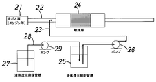
(比較例1)
比較のために、従来の排ガス浄化システムのフローシートを示す図4に基づいて排ガス浄化システムを実施した。
比較のために、従来の排ガス浄化システムのフローシートを示す図4に基づいて排ガス浄化システムを実施した。
同図を参照すると、従来の排ガス浄化システムにおいて、排ガス源21からの排気通路22に、上流側から順に還元剤供給用管(還元剤供給手段)23と脱硝触媒層24が配置され、さらに排ガス浄化システムには、液体還元剤を貯留させるための液体還元剤貯留槽25を備えており、液体還元剤貯留槽25からポンプ26の作動により導出された還元剤を、供給管23から排気通路22内に直接導入して、排ガス中で気化させた。液体還元剤としては、上記実施例1の場合と同様に、エタノール(沸点78.37℃)を使用した。
その結果、液体エタノールの気化熱による排ガス温度の低下が生じて、脱硝触媒層24の入口の排ガス温度は、243℃に低下した。これによって、脱硝触媒層24の脱硝反応の温度が低下するため、触媒層24の脱硝性能は低下したものと考えられる。
下記の表1に、排ガス源21から排気通路22に導入した排ガスの温度と、還元剤供給管23より液体エタノールを排気通路2内に直接供給した後の脱硝触媒層24入口の排ガス温度をあわせて示した。
なお、この比較例1の排ガス浄化システムにおいて、さらに液体還元剤保管槽27を備えており、液体還元剤保管槽27からポンプ29の作動により導管28を経て液体エタノールを液体エタノール貯留槽25に補充するようにした。

上記表1に記載の結果から明らかなように、本発明の実施例1~3の排ガス浄化システムによれば、排ガス温度が250℃程度の比較的低温域の排ガスであっても、エタノールよりなる液体還元剤を用いて、しかも排ガスに添加する際に、事前に気化した還元剤を供給することができるため、液体還元剤の気化熱による排ガス温度の低下を抑制し、脱硝触媒層4入口の温度を低下させることなく、還元剤であるエタノールを添加することができ、脱硝触媒層4での高い脱硝性能を維持することができた。そのうえ、排ガスへの気化還元剤の添加量の制御が容易であり、実用性に優れていることが確認できた。
これに対し、比較例1によれば、脱硝触媒層24の上流側の排気通路22に、エタノールよりなる還元剤を液体の状態で直接導入し、導入から脱硝触媒層24に到達するまでの間にエタノールよりなる還元剤を気化させているため、還元剤の気化熱により排ガスの温度低下生じ、脱硝触媒層4における触媒の脱硝性能が低下するという問題が生じた。
Claims (8)
- 内燃機関の排気通路に、上流側から順に還元剤供給手段と脱硝触媒層が配置され、前記還元剤供給手段より還元剤が前記触媒層上流側の排ガスに添加され、排ガス中の窒素酸化物が還元されて、排ガスが浄化される排ガス浄化システムにおいて、液体還元剤貯留槽と、圧縮空気供給手段とを備えており、前記液体還元剤貯留槽内で気化した還元剤に対して前記圧縮空気供給手段から圧縮空気が供給されて、気化還元剤同伴空気が形成され、この気化還元剤同伴空気が前記還元剤供給手段に供給されることを特徴とする、排ガス浄化システム。
- 前記圧縮空気供給手段から液体還元剤貯留槽内に供給する圧縮空気の流量および貯留槽内液体還元剤温度を制御することにより、排ガスに添加する気化還元剤量を制御することを特徴とする、請求項1に記載の排ガス浄化システム。
- さらに液体還元剤保管槽を備えており、前記液体還元剤貯留槽には液面計が設置され、この液面計からの貯留槽内還元剤液上面のレベル検知信号に基づいて、前記液体還元剤保管槽から液体還元剤貯留槽に供給される還元剤の供給量が制御されることを特徴とする、請求項1または2に記載の排ガス浄化システム。
- 前記液体還元剤貯留槽に加熱手段が備えられ、この加熱手段によって貯留槽内の液体還元剤の温度が調整されることを特徴とする、請求項1~3のうちのいずれか一項に記載の排ガス浄化システム。
- 脱硝触媒層の下流側の排気通路に循環熱媒体加熱用熱交換器が設置され、該熱交換器と前記加熱手段とは熱媒体循環管によって接続されており、該熱交換器において触媒層から排出された浄化排ガスの排熱で、液体還元剤貯留槽の加熱手段からの循環熱媒体が加温されることを特徴とする、請求項4に記載の排ガス浄化システム。
- 内燃機関の排気通路に、上流側から順に還元剤供給手段と脱硝触媒層が配置され、前記還元剤供給手段より還元剤が前記触媒層上流側の排ガスに添加され、排ガス中の窒素酸化物が還元されて、排ガスが浄化される排ガス浄化システムにおいて、液体還元剤貯留槽と、還元剤気化用熱交換器とを備えており、液体還元剤貯留槽から導出された還元剤が熱交換器において加熱されて気化せしめられ、この気化還元剤が、前記還元剤供給手段に供給されることを特徴とする、排ガス浄化システム。
- 還元剤気化用熱交換器が、脱硝触媒層の下流側の排気通路に設置され、該熱交換器において触媒層から排出された浄化排ガスの排熱で液体還元剤が加熱されて気化せしめられることを特徴とする、請求項6に記載の排ガス浄化システム。
- 液体還元剤が、アルコール、エーテル、ケトン類、および炭化水素よりなる群の中から選ばれた少なくとも1つの有機化合物であることを特徴とする、請求項1~7のうちのいずれか一項に記載の排ガス浄化システム。
Applications Claiming Priority (2)
| Application Number | Priority Date | Filing Date | Title |
|---|---|---|---|
| JP2013-028082 | 2013-02-15 | ||
| JP2013028082A JP6140470B2 (ja) | 2013-02-15 | 2013-02-15 | 排ガス浄化システム |
Publications (1)
| Publication Number | Publication Date |
|---|---|
| WO2014126090A1 true WO2014126090A1 (ja) | 2014-08-21 |
Family
ID=51354090
Family Applications (1)
| Application Number | Title | Priority Date | Filing Date |
|---|---|---|---|
| PCT/JP2014/053160 WO2014126090A1 (ja) | 2013-02-15 | 2014-02-12 | 排ガス浄化システム |
Country Status (2)
| Country | Link |
|---|---|
| JP (1) | JP6140470B2 (ja) |
| WO (1) | WO2014126090A1 (ja) |
Cited By (2)
| Publication number | Priority date | Publication date | Assignee | Title |
|---|---|---|---|---|
| CN112879126A (zh) * | 2021-01-21 | 2021-06-01 | 天津大学 | 一种无催化的双还原剂NOx脱除方法及其装置 |
| US11649761B1 (en) | 2021-12-22 | 2023-05-16 | Caterpillar Inc. | Systems for methanol vaporization |
Families Citing this family (1)
| Publication number | Priority date | Publication date | Assignee | Title |
|---|---|---|---|---|
| GB201421869D0 (en) * | 2014-12-09 | 2015-01-21 | Delphi International Operations Luxembourg S.�.R.L. | SCR dosing system |
Citations (5)
| Publication number | Priority date | Publication date | Assignee | Title |
|---|---|---|---|---|
| JPH05272331A (ja) * | 1992-03-25 | 1993-10-19 | Hino Motors Ltd | 排ガス浄化装置およびその排ガス浄化装置に使用される還元剤供給方法および装置 |
| JPH09267025A (ja) * | 1996-03-29 | 1997-10-14 | Kawasaki Heavy Ind Ltd | 排ガス脱硝用還元剤の供給方法 |
| JP2002221024A (ja) * | 2001-01-22 | 2002-08-09 | Kawasaki Heavy Ind Ltd | 脱硝装置用液体還元剤の供給方法及び装置 |
| JP2010138883A (ja) * | 2008-12-15 | 2010-06-24 | Denso Corp | 排気浄化システムの制御装置 |
| WO2013114614A1 (ja) * | 2012-02-03 | 2013-08-08 | トヨタ自動車株式会社 | 内燃機関の排気浄化装置 |
-
2013
- 2013-02-15 JP JP2013028082A patent/JP6140470B2/ja active Active
-
2014
- 2014-02-12 WO PCT/JP2014/053160 patent/WO2014126090A1/ja active Application Filing
Patent Citations (5)
| Publication number | Priority date | Publication date | Assignee | Title |
|---|---|---|---|---|
| JPH05272331A (ja) * | 1992-03-25 | 1993-10-19 | Hino Motors Ltd | 排ガス浄化装置およびその排ガス浄化装置に使用される還元剤供給方法および装置 |
| JPH09267025A (ja) * | 1996-03-29 | 1997-10-14 | Kawasaki Heavy Ind Ltd | 排ガス脱硝用還元剤の供給方法 |
| JP2002221024A (ja) * | 2001-01-22 | 2002-08-09 | Kawasaki Heavy Ind Ltd | 脱硝装置用液体還元剤の供給方法及び装置 |
| JP2010138883A (ja) * | 2008-12-15 | 2010-06-24 | Denso Corp | 排気浄化システムの制御装置 |
| WO2013114614A1 (ja) * | 2012-02-03 | 2013-08-08 | トヨタ自動車株式会社 | 内燃機関の排気浄化装置 |
Cited By (2)
| Publication number | Priority date | Publication date | Assignee | Title |
|---|---|---|---|---|
| CN112879126A (zh) * | 2021-01-21 | 2021-06-01 | 天津大学 | 一种无催化的双还原剂NOx脱除方法及其装置 |
| US11649761B1 (en) | 2021-12-22 | 2023-05-16 | Caterpillar Inc. | Systems for methanol vaporization |
Also Published As
| Publication number | Publication date |
|---|---|
| JP2014156821A (ja) | 2014-08-28 |
| JP6140470B2 (ja) | 2017-05-31 |
Similar Documents
| Publication | Publication Date | Title |
|---|---|---|
| EP1901831B1 (en) | Method and device for safe and controlled delivery of ammonia from a solid ammonia storage medium | |
| JP7417013B2 (ja) | 火力発電所の排ガス処理方法 | |
| JP6140470B2 (ja) | 排ガス浄化システム | |
| JP2011122593A (ja) | 内燃機関の排気ガスに含まれている汚染物質を処理する方法およびそれを用いた汚染物質処理システム | |
| JP4646063B2 (ja) | 尿素の分解触媒を用いた排ガス脱硝方法及び装置 | |
| KR20190091480A (ko) | 암모늄 카르바메이트의 제조 및 질소 옥사이드의 환원 | |
| JP5383648B2 (ja) | 低温尿素噴射法 | |
| JP6850413B2 (ja) | 火力発電所の排ガス処理装置 | |
| JP5908059B2 (ja) | 発電装置、発電方法、分解ガスボイラー及び分解ガスタービン | |
| KR102359951B1 (ko) | 촉매 및 촉매의 제조 방법 | |
| JP2009035644A (ja) | 尿素scrシステム用不凍尿素溶液および尿素scrシステム | |
| JP6175510B2 (ja) | 選択接触還元システムにおける尿素調整及び噴射制御のための方法及び装置 | |
| CN105102782A (zh) | 排气净化系统的脱硝催化剂的现场再生方法 | |
| JP4661452B2 (ja) | 排気ガス浄化システムの制御方法及び排気ガス浄化システム | |
| CN101617104A (zh) | 用于在机动车的内燃机中产生废气处理用氨的方法和设备 | |
| US20130045139A1 (en) | Method To Enhance The Ash Storage Capacity Of A Particulate Filter | |
| CN207822795U (zh) | 综合式船舶码头油气超低排放回收装置 | |
| JP2013130179A (ja) | 内燃機関の制御装置 | |
| KR20100117231A (ko) | 배기가스 정화장치 및 배기가스 정화방법 | |
| JPH08257365A (ja) | 排ガス脱硝方法及び装置 | |
| JP2011144055A (ja) | 燃料改質装置 | |
| JP2014105143A (ja) | アンモニア発生装置及びそれを用いた排気浄化装置 | |
| JP2004251196A (ja) | 改質ガス製造装置、これを用いた改質ガス製造方法及び排気浄化システム | |
| TW201104062A (en) | De-NOx, intelligent, full-featured diesel engine exhaust treatment system | |
| JP2021515872A (ja) | 選択触媒還元システム及びNOx還元方法 |
Legal Events
| Date | Code | Title | Description |
|---|---|---|---|
| 121 | Ep: the epo has been informed by wipo that ep was designated in this application |
Ref document number: 14751623 Country of ref document: EP Kind code of ref document: A1 |
|
| NENP | Non-entry into the national phase |
Ref country code: DE |
|
| 122 | Ep: pct application non-entry in european phase |
Ref document number: 14751623 Country of ref document: EP Kind code of ref document: A1 |