WO2014125874A1 - 位置検出器の精度補正方法 - Google Patents
位置検出器の精度補正方法 Download PDFInfo
- Publication number
- WO2014125874A1 WO2014125874A1 PCT/JP2014/050893 JP2014050893W WO2014125874A1 WO 2014125874 A1 WO2014125874 A1 WO 2014125874A1 JP 2014050893 W JP2014050893 W JP 2014050893W WO 2014125874 A1 WO2014125874 A1 WO 2014125874A1
- Authority
- WO
- WIPO (PCT)
- Prior art keywords
- interpolation error
- node
- scale
- pitch
- average
- Prior art date
- Legal status (The legal status is an assumption and is not a legal conclusion. Google has not performed a legal analysis and makes no representation as to the accuracy of the status listed.)
- Ceased
Links
Images


Classifications
-
- G—PHYSICS
- G01—MEASURING; TESTING
- G01D—MEASURING NOT SPECIALLY ADAPTED FOR A SPECIFIC VARIABLE; ARRANGEMENTS FOR MEASURING TWO OR MORE VARIABLES NOT COVERED IN A SINGLE OTHER SUBCLASS; TARIFF METERING APPARATUS; MEASURING OR TESTING NOT OTHERWISE PROVIDED FOR
- G01D5/00—Mechanical means for transferring the output of a sensing member; Means for converting the output of a sensing member to another variable where the form or nature of the sensing member does not constrain the means for converting; Transducers not specially adapted for a specific variable
- G01D5/12—Mechanical means for transferring the output of a sensing member; Means for converting the output of a sensing member to another variable where the form or nature of the sensing member does not constrain the means for converting; Transducers not specially adapted for a specific variable using electric or magnetic means
- G01D5/14—Mechanical means for transferring the output of a sensing member; Means for converting the output of a sensing member to another variable where the form or nature of the sensing member does not constrain the means for converting; Transducers not specially adapted for a specific variable using electric or magnetic means influencing the magnitude of a current or voltage
- G01D5/20—Mechanical means for transferring the output of a sensing member; Means for converting the output of a sensing member to another variable where the form or nature of the sensing member does not constrain the means for converting; Transducers not specially adapted for a specific variable using electric or magnetic means influencing the magnitude of a current or voltage by varying inductance, e.g. by a movable armature
- G01D5/204—Mechanical means for transferring the output of a sensing member; Means for converting the output of a sensing member to another variable where the form or nature of the sensing member does not constrain the means for converting; Transducers not specially adapted for a specific variable using electric or magnetic means influencing the magnitude of a current or voltage by varying inductance, e.g. by a movable armature by influencing the mutual induction between two or more coils
- G01D5/2073—Mechanical means for transferring the output of a sensing member; Means for converting the output of a sensing member to another variable where the form or nature of the sensing member does not constrain the means for converting; Transducers not specially adapted for a specific variable using electric or magnetic means influencing the magnitude of a current or voltage by varying inductance, e.g. by a movable armature by influencing the mutual induction between two or more coils by movement of a single coil with respect to two or more coils
-
- G—PHYSICS
- G01—MEASURING; TESTING
- G01D—MEASURING NOT SPECIALLY ADAPTED FOR A SPECIFIC VARIABLE; ARRANGEMENTS FOR MEASURING TWO OR MORE VARIABLES NOT COVERED IN A SINGLE OTHER SUBCLASS; TARIFF METERING APPARATUS; MEASURING OR TESTING NOT OTHERWISE PROVIDED FOR
- G01D3/00—Indicating or recording apparatus with provision for the special purposes referred to in the subgroups
- G01D3/028—Indicating or recording apparatus with provision for the special purposes referred to in the subgroups mitigating undesired influences, e.g. temperature, pressure
- G01D3/036—Indicating or recording apparatus with provision for the special purposes referred to in the subgroups mitigating undesired influences, e.g. temperature, pressure on measuring arrangements themselves
-
- G—PHYSICS
- G01—MEASURING; TESTING
- G01D—MEASURING NOT SPECIALLY ADAPTED FOR A SPECIFIC VARIABLE; ARRANGEMENTS FOR MEASURING TWO OR MORE VARIABLES NOT COVERED IN A SINGLE OTHER SUBCLASS; TARIFF METERING APPARATUS; MEASURING OR TESTING NOT OTHERWISE PROVIDED FOR
- G01D5/00—Mechanical means for transferring the output of a sensing member; Means for converting the output of a sensing member to another variable where the form or nature of the sensing member does not constrain the means for converting; Transducers not specially adapted for a specific variable
- G01D5/12—Mechanical means for transferring the output of a sensing member; Means for converting the output of a sensing member to another variable where the form or nature of the sensing member does not constrain the means for converting; Transducers not specially adapted for a specific variable using electric or magnetic means
- G01D5/14—Mechanical means for transferring the output of a sensing member; Means for converting the output of a sensing member to another variable where the form or nature of the sensing member does not constrain the means for converting; Transducers not specially adapted for a specific variable using electric or magnetic means influencing the magnitude of a current or voltage
- G01D5/20—Mechanical means for transferring the output of a sensing member; Means for converting the output of a sensing member to another variable where the form or nature of the sensing member does not constrain the means for converting; Transducers not specially adapted for a specific variable using electric or magnetic means influencing the magnitude of a current or voltage by varying inductance, e.g. by a movable armature
- G01D5/204—Mechanical means for transferring the output of a sensing member; Means for converting the output of a sensing member to another variable where the form or nature of the sensing member does not constrain the means for converting; Transducers not specially adapted for a specific variable using electric or magnetic means influencing the magnitude of a current or voltage by varying inductance, e.g. by a movable armature by influencing the mutual induction between two or more coils
- G01D5/2066—Mechanical means for transferring the output of a sensing member; Means for converting the output of a sensing member to another variable where the form or nature of the sensing member does not constrain the means for converting; Transducers not specially adapted for a specific variable using electric or magnetic means influencing the magnitude of a current or voltage by varying inductance, e.g. by a movable armature by influencing the mutual induction between two or more coils by movement of a single coil with respect to a single other coil
Definitions
- the present invention relates to an accuracy correction method for a position detector.
- Induct thin type scale which is an electromagnetic induction type position detector, is applied to position detection units of various machines such as machine tools, automobiles and robots.
- Induct thin type scales include linear scales and rotary scales.
- Linear scales are applied to, for example, a linear movement axis of a machine tool to detect a movement position on the linear movement axis, and a rotary scale.
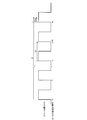
- the linear scale and the rotary scale detect the position by electromagnetic induction of coil patterns arranged in parallel and face to face. This detection principle will be described based on the principle diagram of FIG. 5A is a perspective view showing a state in which the slider of the linear scale and the scale face each other in parallel.
- FIG. 5B is a schematic view showing the slider and the scale side by side. FIG. These are graphs showing the degree of electromagnetic coupling between the slider and the scale.
- FIG. 5 shows the principle of the linear scale, but the principle of the rotary scale is the same, and the stator and rotor of the rotary scale correspond to the slider and scale of the linear scale, respectively. .
- the detection unit of the linear scale has a slider 11 as a primary member and a scale 12 as a secondary member.
- the slider 11 which is a movable part has a first slider side coil 13 as a first primary side coil and a second slider side coil 14 as a second primary side coil, and the scale 12 which is a fixed part.
- These coils 13, 14, and 15 are folded back in a zigzag shape (that is, formed in a comb pattern) and are entirely linear. Further, the coils 13, 14, and 15 have the same length of one pitch.
- the first slider-side coil 13, the second slider-side coil 14, and the scale-side coil 15 are in parallel with a gap g within a specified range being held between them. It is arranged to face. Further, as shown in FIGS. 5A and 5B, the relationship between the first slider side coil 13 and the second slider side coil 14 and the scale side coil 15 is shifted by 1 ⁇ 4 pitch.
- the first slider-side coil 13 and the second slider-side coil 14 and the scale-side coil 15 change according to the change in the relative positional relationship between the scale-side coil 15 and the first slider-side coil 13 and the second slider-side coil. Since the degree of electromagnetic coupling between the second slider-side coil 14 and the scale-side coil 15 changes periodically, a voltage that periodically changes is generated in the scale-side coil 15. Therefore, the position of the scale 12 (that is, the position of the slider 11 with respect to the scale 12) can be detected based on the voltage.
- first slider side coil 13 flowing first alternating current I s below, and the second slider side coil 14 flow below the second alternating current I c.
- I s ⁇ I ⁇ cos (k ⁇ ) ⁇ sin ( ⁇ t)
- I c I ⁇ sin (k ⁇ ) ⁇ sin ( ⁇ t)
- the following voltage V is generated in the scale coil 13 if it is an ideal linear scale (or rotary scale).
- V K (g) ⁇ I ⁇ sin (k (X ⁇ )) ⁇ sin ( ⁇ t) (1)
- K coefficient depending on the gap g X: detection position of the scale (detection position of the slider in the longitudinal direction with respect to the scale)
- V p K (g) ⁇ I ⁇ sin (k (X ⁇ )) (2)
- the error that appears prominently is a coil pitch (pattern pitch) period / integer period error in the coil on the scale side, which is called an interpolation error.
- the actual interpolation error will not be completely cyclic, but will vary from coil pitch to coil pitch.
- an object of the present invention is to provide a position detector accuracy correction method that simply performs interpolation error correction that is resistant to secular change.
- the accuracy correction method of the position detector according to the first invention for solving the above-mentioned problem is as follows.
- a position detector that detects the position by changing the relative position of the primary side member in which the object to be measured is arranged in a pattern at a constant pitch and the secondary side member that is a measurement unit at a constant speed or angular velocity.
- the accuracy correction method of The relative position of the secondary side member passes through the length of one pitch or the angle p from the passage of the n-th node of the object to be measured to the arrival of the (n + 1) -th node.
- the displacement amount G n [i] at the time i ⁇ ⁇ t (i is a natural number of sampling numbers 0 to N ⁇ 1) within the pitch range detected every interval ⁇ t is stored,
- the current detection position that is the relative position of the secondary member is the detection position G m within the pitch range from the m-th node to the m + 1-th node, and na ⁇ m ⁇ m ⁇ n + a (a is Is an integer defined in advance), an interpolation error E n [I] of
- the accuracy correction method of the position detector according to the second invention for solving the above-mentioned problem is as follows.
- Said interpolation error E n [i] a k in the past (k: integer) times acquired if seeking average the interpolation error E na [i], including the current in said interpolation error E n [i]
- the relative position between the primary side member in which the object to be measured is arranged in a pattern at a constant pitch and the secondary side member that is a measurement unit is constant.
- This is a method of correcting the accuracy of a position detector that detects a position by changing the velocity or angular velocity of the secondary side member after the relative position of the secondary member has passed through the n-th node of the object to be measured.
- the time i ⁇ ⁇ t (i is a sampling number 0 to N ⁇ 1) within the pitch range detected every fixed time interval ⁇ t while moving the length or angle p of one pitch until reaching the (n + 1) th node.
- the detection position which is the relative position of the member, is the detection position G m within the pitch range from the m-th node to the m + 1-th node, and na ⁇ m ⁇ m ⁇ n + a (a is a predetermined integer)
- an interpolation error E n [I] of i I that minimizes
- is obtained, and a detection position X ′ that is a position from the
- (A) is a perspective view showing a state in which the slider of the linear scale and the scale are faced in parallel
- (b) is a schematic view showing the slider and the scale side by side
- (c) is the slider. And a graph showing the degree of electromagnetic coupling of the scale.
- the electromagnetic induction scale is electromagnetically coupled with a plurality of coils, so the degree of coupling is averaged. Therefore, the distribution of the interpolation error between two adjacent coil pitches is similar. Therefore, in the accuracy correction method of the position detector according to the present invention, correction is performed using the error of the adjacent coil pitch.
- FIG. 1 is a flowchart illustrating this method.
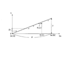
- FIG. 2 is a schematic diagram for explaining the relationship among the coil pitch, the detection position, and the joint.
- FIG. 3 is a graph showing the relationship between the displacement amount within the coil pitch range, the time, and the interpolation error.
- the horizontal axis is the displacement amount G n [i] (see below for details) within the coil pitch range, and the vertical axis. The axis indicates time t.
- step S1 the slider passes through the nth node of the scale side coil in FIG.
- step S2 in FIG. 2, while the slider moves a length p of 1 pitch from the passage of the n-th node of the scale side coil to the arrival of the next (n + 1) -th node, it is constant.
- a displacement amount at time i ⁇ ⁇ t (i is a natural number of sampling numbers 0 to N ⁇ 1) within the coil pitch range detected at each time interval ⁇ t is defined as a displacement amount G n [i], and the displacement amount G n [i ] Is memorized.
- step S3 it is determined whether or not the time T (see FIG. 3) for moving from the nth to the (n + 1) th p is less than a specified time. If it is less than the specified time, it is assumed that the moving speed of the slider from the nth to the (n + 1) th is high, and the process proceeds to step S4. If it is longer than the specified time, it is considered that the moving speed is not high, and the process returns to step S1.
- step S5 the interpolation error E n [i] is determined whether the following prescribed value. If it is less than the specified value, the process proceeds to step S6. If it is greater than the specified value, it is determined that the interpolation error of the scale side coil is too large (error could not be detected), and the process returns to step S1.
- step S6 obtains the interpolation error E n [i] k times in the past, if obtaining an average in the interpolation error E na [i], including current in said interpolation error E n [i] Mean
- the interpolation error E na ′ [i] may be obtained by the following formula (the interpolation error E n [i] is always stored in the EEPROM so that it can be used even after the power supply is restarted).
- E na ′ [i] (E n [i] + k ⁇ E na [i]) / (k + 1)
- the interpolation error data is acquired by the above steps S1 to S6.
- the “return to step S1” means that the process is performed again from step S1 at the next coil pitch.
- step S7 the detection position X is corrected by the following procedure.
- the detection position X before correction and the detection position within the coil pitch range can be detected simultaneously by the conventional technique.
- the detection position that is the current slider position is the detection position G m within the coil pitch range from the m-th node to the m + 1-th node, and the detection position from the zero position of the scale side coil before correction X is calculated
- the m-th node of the scale side coil is close to the n-th node from which the interpolation error data was acquired in steps S1 to S6, that is, na ⁇ m ⁇ n + a (a is a predefined integer. ), I that minimizes
- step S6 the average in the interpolation error E na 'when seeking [i] is,
- mean the interpolation error of the minimum i I E na' [I ]
- the corrected detection position X ′ which is the position from the zero position of the scale side coil, is obtained from the following equation.
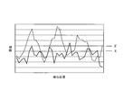
- FIG. 4 is a graph showing the relationship between the detection position and the error when correction is performed using this method.
- the horizontal axis indicates the actual detection position
- the vertical axis indicates the actual detection position
- the detection positions X and X The solid line in the graph is data relating to X ′
- the broken line in the graph is data relating to X. As shown in the graph, an error between the corrected detection position X ′ and the actual detection position is reduced as compared with the detection position X before correction.
- the driving for correction may be performed by moving the entire stroke at a high speed and a constant speed in advance.
- the scale may be replaced with a stator, the scale with a rotor, the length with an angle, and the speed with an angular speed.
- the application target of this method is not limited to the scale of the inductive method that is an electromagnetic induction type position detector.
- the above steps S1 to S7 can be applied.
- the slider is set to the light source 11, the collimator lens 12, the index scale 16 and the light receiving element 17, the scale side coil is set to the grid 14 in the main scale 13, and the coil pitch is set to the pitch P of the grid 14.
- the movable part in the optical encoder disclosed in FIG. 5 of JP-A-4-125409 is not a slider (light source 11, collimator lens 12, index scale 16 and light receiving element 17), but a scale and a scale side coil ( A grid 14) in the main scale 13 is obtained.
- this method is a primary side member in which a measurement target is arranged in a pattern at a constant pitch, and a measurement unit.
- An accuracy correction method for a position detector that detects a position by changing a relative position with a secondary member at a constant speed or angular velocity, wherein the relative position of the secondary member is the measured object The time i ⁇ within the pitch range detected at fixed time intervals ⁇ t while moving the length or angle p of one pitch from the passage of the target nth node to the arrival of the (n + 1) th node.
- the method further said interpolation error E n [i] a k in the past (k: integer) times acquired if seeking average the interpolation error E na [i], within the interpolation error of the current E n
- the average interpolation error E na ′ [I] of i I that minimizes n [i]
- the present invention is suitable as a method for correcting the accuracy of the position detector.
Landscapes
- Physics & Mathematics (AREA)
- General Physics & Mathematics (AREA)
- Transmission And Conversion Of Sensor Element Output (AREA)
Abstract
n番目の節目からn+1番目の節目までを移動する時間をTとし、平均速度SをS=p/Tより求め、内挿誤差En[i]をEn[i]=Gn[i]-i・S・Δt-Gn[0]より求め、現在の二次側部材の相対位置が検出位置Gmであるものとし、n-a≦m≦n+a(aは予め規定した整数)のとき、|Gm-Gn[i]|が最小となるi=Iの内挿誤差En[I]を求め、検出位置X´をX´=p・m+Gm-En[I]より求めることで、経年変化に強い内挿誤差補正を簡易的に行う、位置検出器の精度補正方法を提供することができる。
Description
本発明は、位置検出器の精度補正方法に関する。
電磁誘導式位置検出器であるインダクトシン方式のスケールは、工作機械、自動車及びロボットなどの各種機械の位置検出部に適用される。インダクトシン方式のスケールにはリニア形スケールとロータリ形スケールとがあり、リニア形スケールは、例えば工作機械の直線移動軸に適用されて当該直線移動軸上の移動位置を検出し、ロータリ形スケールは、例えば工作機械の回転軸に適用されて当該回転軸の回転角度を検出する。
リニア形スケール及びロータリ形スケールは、平行に向かい合わせに配置したコイルパターンの電磁誘導により位置を検出するものである。この検出原理を図5の原理図に基づいて説明する。図5(a)はリニア形スケールのスライダとスケールを平行に向い合せにした状態を示した斜視図、図5(b)は前記スライダと前記スケールを並べて示した模式図、図5(c)は、前記スライダと前記スケールの電磁結合度を示したグラフである。なお、図5にはリニア形スケールの原理図を示しているが、ロータリ形スケールの原理も同様であり、ロータリ形スケールのステータとロータが、それぞれリニア形スケールのスライダとスケールに対応している。
図5(a)(b)に示すように、リニア形スケールの検出部は一次部材としてのスライダ11と二次部材としてのスケール12とを有している。可動部であるスライダ11は第1の一次側コイルとしての第1スライダ側コイル13と、第2の一次側コイルとしての第2スライダ側コイル14とを有しており、固定部であるスケール12は二次側コイルとしてのスケール側コイル15を有している。これらのコイル13,14,15はジグザグ状に折り返され(すなわち櫛型パターンに形成され)かつ全体が直線状となっている。また、コイル13,14,15は互いに1ピッチの長さが等しくなっている。
そして、図5(a)に示すように、第1スライダ側コイル13及び第2スライダ側コイル14と、スケール側コイル15は、これらの間に規定の範囲内のギャップgを保持した状態で平行に向い合せて配置されている。また、図5(a)及び図5(b)に示すように、第1スライダ側コイル13と第2スライダ側コイル14とは、スケール側コイル15との関係が1/4ピッチずれている。
よって、第1スライダ側コイル13と第2スライダ側コイル14とに交流電流を流し、スライダ11が図5(a)の矢印Aの如くスケール12の長手方向に沿って移動すると、このスライダ11の移動による第1スライダ側コイル13及び第2スライダ側コイル14と、スケール側コイル15との相対的な位置関係の変化に応じて、図5(c)に示すように第1スライダ側コイル13及び第2スライダ側コイル14と、スケール側コイル15との電磁結合度が周期的に変化するため、スケール側コイル15には周期的に変化する電圧が発生する。したがって、当該電圧に基づいてスケール12の位置(すなわちスケール12に対するスライダ11の位置)を検出することができる。
ここで、第1スライダ側コイル13に下記第1交流電流Isを流し、第2スライダ側コイル14に下記第2交流電流Icを流すとする。
Is=-I・cos(kα)・sin(ωt)
Ic=I・sin(kα)・sin(ωt)
ただし、I:電流の大きさ
p:コイルの1ピッチの長さ(ロータリ形スケールでは角度)
k:2π/p
ω:交流電流の角周波数
t:時刻
α:励振位置
Ic=I・sin(kα)・sin(ωt)
ただし、I:電流の大きさ
p:コイルの1ピッチの長さ(ロータリ形スケールでは角度)
k:2π/p
ω:交流電流の角周波数
t:時刻
α:励振位置
このような場合、理想的なリニア形スケール(又はロータリ形スケール)であれば、スケールコイル13には下記電圧Vが発生する。
V=K(g)・I・sin(k(X-α))・sin(ωt) …(1)
ただし、K:ギャップgに依存する係数
X:スケールの検出位置(スケールに対しての長手方向におけるスライダの検出位置)
ただし、K:ギャップgに依存する係数
X:スケールの検出位置(スケールに対しての長手方向におけるスライダの検出位置)
また、上記(1)式をサンプリングした、電圧Vのピーク振幅Vpは、下記値となる。
Vp=K(g)・I・sin(k(X-α)) …(2)
そこで、検出位置Xに対し励振位置αを追従させて、α=XすなわちVp=0となるように制御し、このときの励振位置αの値を、検出位置Xとする。
しかしながら、現実のリニア形スケール(又はロータリ形スケール)は、製造誤差や組付誤差により上記(2)式の関係が成立せず、検出位置Xには誤差が伴う。
一般的に誤差として顕著に現れるのは、スケール側コイルにおけるコイルピッチ(パターンピッチ)周期/整数の周期誤差であり、これを内挿誤差という。
製造誤差によるパターンの不均一性や、スケール側コイルとスライダ側コイルの傾きの変化により、実際の内挿誤差は、完全にサイクリックなものとはならず、コイルピッチごとに異なるものとなる。
よって、スケール側コイルにおける全てのコイルピッチに対して同一の補正値を用いて補正を行っても、内挿誤差の除去が困難であるという課題がある。
また、上記特許文献1のように、スケール側コイルにおける各コイルピッチの内挿誤差を予め記憶して、その値を用いて補正を行うといった手段では、余計な手間がかかってしまい、さらには取付けの経年変化による内挿誤差の変動を補正することができないという課題がある。
そこで本発明では、経年変化に強い内挿誤差補正を簡易的に行う、位置検出器の精度補正方法を提供することを目的とする。
上記課題を解決する第1の発明に係る位置検出器の精度補正方法は、
被測定対象が一定のピッチでパターン配置される一次側部材と、測定部である二次側部材との相対位置を、一定の速度又は角速度で変化させることで、位置の検出を行う位置検出器の精度補正方法であって、
前記二次側部材の相対位置が、前記被測定対象のn番目の節目を通過してからn+1番目の節目に到達するまでの、1ピッチの長さ又は角度pを移動する間に、一定時間間隔Δtごとに検出したピッチ範囲内における時刻i・Δt(iはサンプリング番号0~N-1の自然数)での変位量Gn[i]を記憶し、
前記n番目の節目から前記n+1番目の節目までの前記pを移動する時間をTとし、平均速度又は平均角速度Sを
S=p/T
より求め、
前記n番目の節目から前記n+1番目の節目までのピッチでの内挿誤差En[i]を
En[i]=Gn[i]-i・S・Δt-Gn[0]
より求め、
現在の前記二次側部材の相対位置である検出位置が、m番目の節目からm+1番目の節目までのピッチ範囲内における検出位置Gmであるものとし、n-a≦m≦n+a(aは予め規定した整数)である場合、|Gm-Gn[i]|が最小となるi=Iの内挿誤差En[I]を求め、前記被測定対象の零点位置からの位置である検出位置X´を
X´=p・m+Gm-En[I]
より求める
ことを特徴とする。
被測定対象が一定のピッチでパターン配置される一次側部材と、測定部である二次側部材との相対位置を、一定の速度又は角速度で変化させることで、位置の検出を行う位置検出器の精度補正方法であって、
前記二次側部材の相対位置が、前記被測定対象のn番目の節目を通過してからn+1番目の節目に到達するまでの、1ピッチの長さ又は角度pを移動する間に、一定時間間隔Δtごとに検出したピッチ範囲内における時刻i・Δt(iはサンプリング番号0~N-1の自然数)での変位量Gn[i]を記憶し、
前記n番目の節目から前記n+1番目の節目までの前記pを移動する時間をTとし、平均速度又は平均角速度Sを
S=p/T
より求め、
前記n番目の節目から前記n+1番目の節目までのピッチでの内挿誤差En[i]を
En[i]=Gn[i]-i・S・Δt-Gn[0]
より求め、
現在の前記二次側部材の相対位置である検出位置が、m番目の節目からm+1番目の節目までのピッチ範囲内における検出位置Gmであるものとし、n-a≦m≦n+a(aは予め規定した整数)である場合、|Gm-Gn[i]|が最小となるi=Iの内挿誤差En[I]を求め、前記被測定対象の零点位置からの位置である検出位置X´を
X´=p・m+Gm-En[I]
より求める
ことを特徴とする。
上記課題を解決する第2の発明に係る位置検出器の精度補正方法は、
上記第1の発明に係る位置検出器の精度補正方法において、
過去に前記内挿誤差En[i]をk(k:整数)回取得し、平均内挿誤差Ena[i]を求めていれば、今回の前記内挿誤差En[i]を含んだ平均内挿誤差Ena´[i]を
Ena´[i]=(En[i]+k・Ena[i])/(k+1)
より求め、
|Gm-Gn[i]|が最小となるi=Iの平均内挿誤差Ena´[I]を求め、前記検出位置X´を
X´=p・m+Gm-Ena´[I]
より求める
ことを特徴とする。
上記第1の発明に係る位置検出器の精度補正方法において、
過去に前記内挿誤差En[i]をk(k:整数)回取得し、平均内挿誤差Ena[i]を求めていれば、今回の前記内挿誤差En[i]を含んだ平均内挿誤差Ena´[i]を
Ena´[i]=(En[i]+k・Ena[i])/(k+1)
より求め、
|Gm-Gn[i]|が最小となるi=Iの平均内挿誤差Ena´[I]を求め、前記検出位置X´を
X´=p・m+Gm-Ena´[I]
より求める
ことを特徴とする。
上記第1の発明に係る位置検出器の精度補正方法によれば、被測定対象が一定のピッチでパターン配置される一次側部材と、測定部である二次側部材との相対位置を、一定の速度又は角速度で変化させることで、位置の検出を行う位置検出器の精度補正方法であって、前記二次側部材の相対位置が、前記被測定対象のn番目の節目を通過してからn+1番目の節目に到達するまでの、1ピッチの長さ又は角度pを移動する間に、一定時間間隔Δtごとに検出したピッチ範囲内における時刻i・Δt(iはサンプリング番号0~N-1の自然数)での変位量Gn[i]を記憶し、前記n番目の節目から前記n+1番目の節目までの前記pを移動する時間をTとし、平均速度又は平均角速度SをS=p/Tより求め、前記n番目の節目から前記n+1番目の節目までのピッチでの内挿誤差En[i]をEn[i]=Gn[i]-i・S・Δt-Gn[0]より求め、現在の前記二次側部材の相対位置である検出位置が、m番目の節目からm+1番目の節目までのピッチ範囲内における検出位置Gmであるものとし、n-a≦m≦n+a(aは予め規定した整数)である場合、|Gm-Gn[i]|が最小となるi=Iの内挿誤差En[I]を求め、前記被測定対象の零点位置からの位置である検出位置X´をX´=p・m+Gm-En[I]より求めるので、経年変化に強い内挿誤差補正を簡易的に行うことが可能となる。
上記第2の発明に係る位置検出器の精度補正方法によれば、過去に前記内挿誤差En[i]をk(k:整数)回取得し、平均内挿誤差Ena[i]を求めていれば、今回の前記内挿誤差En[i]を含んだ平均内挿誤差Ena´[i]をEna´[i]=(En[i]+k・Ena[i])/(k+1)より求め、|Gm-Gn[i]|が最小となるi=Iの平均内挿誤差Ena´[I]を求め、前記検出位置X´をX´=p・m+Gm-Ena´[I]より求めるので、運転を繰り返すほど補正精度が向上する。
電磁誘導式スケールは複数のコイルで電磁結合するので結合度は平均化される。それゆえ、隣同士の2つのコイルピッチの内挿誤差の分布は似通っている。よって、本発明に係る位置検出器の精度補正方法では、近接するコイルピッチの誤差を用いて補正を行う。
すなわち、本発明に係る位置検出器の精度補正方法では、スライダの移動中に、現在の位置に近接するコイルピッチでの誤差を取得して、内挿誤差データ(補正データ)を求め、当該データを用いて現在の位置のコイルピッチでの補正を行うという作業を、各コイルピッチに対して行う。これにより、内挿誤差のコイルピッチ位置依存性を低減して補正することができる。
以下、本発明に係る位置検出器の精度補正方法を実施例にて図面を用いて説明する。
本発明の実施例1に係る位置検出器の精度補正方法について図面を用いて説明する。図1は本方法を説明するフローチャートである。また、図2はコイルピッチと検出位置と節目との関係を説明する模式図である。さらに、図3はコイルピッチ範囲内における変位量と時間と内挿誤差との関係を示すグラフであり、横軸がコイルピッチ範囲内における変位量Gn[i](詳細は下記参照)、縦軸が時間tを示している。以下、図1のフローチャートに基づいて説明する。
ステップS1では、図2において、スライダがスケール側コイルのn番目の節目を通過する。
ステップS2では、図2において、スライダが、スケール側コイルのn番目の節目を通過してから隣(n+1番目)の節目に到達するまでの、1ピッチの長さpを移動する間に、一定時間間隔Δtごとに検出したコイルピッチ範囲内における時刻i・Δt(iはサンプリング番号0~N-1の自然数)での変位量を変位量Gn[i]とし、当該変位量Gn[i]を記憶する。
上記一定時間間隔Δtと上記変位量Gn[i]との関係の一例を、図3のグラフ中では黒点として示している。当該黒点の縦軸上の間隔は全てΔtである。なお、図3中のグラフに示すように、Gn[N]-Gn[0]=pであり、通常はGn[0]=0である。
ステップS3では、上記n番目から上記n+1番目までの上記pを移動する時間T(図3参照)が、規定時間未満であるか否かを判断する。規定時間未満の場合は、上記n番目からn+1番目におけるスライダの移動速度は高速であるとみなして、ステップS4に移行する。規定時間以上の場合は、前記移動速度が高速でないとみなして、ステップS1に戻る。
ステップS4では、平均速度S=p/Tから、上記n番目の節目から上記n+1番目の節目までのコイルピッチでの内挿誤差En[i]を下記式にて求める。
En[i]=Gn[i]-i・S・Δt-Gn[0]
すなわち、スライダが一定の速度でpをTで通過する場合の理想的なGn[i]とΔtとの関係は、図3のグラフ中の斜めの直線となるが、現実には黒点の位置となるものとすると、各黒点から前記実線にそれぞれ横軸方向に線分を引いたとき、当該線分の長さが内挿誤差En[i]となる。この手順を数式化したものが上記式である。
ステップS5では、内挿誤差En[i]が規定値以下か否かを判断する。規定値以下の場合は、ステップS6へ移行し、規定値より大きい場合は、スケール側コイルの内挿誤差としては大きすぎる(誤差の検出ができなかった)と判断し、ステップS1に戻る。
ステップS6では、過去に内挿誤差En[i]をk回取得し、平均内挿誤差Ena[i]を求めていれば、今回の前記内挿誤差En[i]を含んだ平均内挿誤差Ena´[i]を下記式にて求めてもよい(内挿誤差En[i]は常にEEPROMに記憶し、電源再起動後も活用できるようにしておく)。
Ena´[i]=(En[i]+k・Ena[i])/(k+1)
本方法では、上記ステップS1~S6によって、内挿誤差データを取得する。なお、上記「ステップS1に戻る」とは、次のコイルピッチにおいて再度ステップS1から行うという意味である。
ステップS7では、下記手順により検出位置Xの補正を行う。
まず、従来技術により、補正前の検出位置Xとコイルピッチ範囲内における検出位置とは同時に検出できる。現在のスライダの位置である検出位置が、m番目の節目からm+1番目の節目までのコイルピッチ範囲内における検出位置Gmであるものとし、補正前の、スケール側コイルの零点位置からの検出位置Xは下記式より求められる。
X=p・m+Gm
ここで、スケール側コイルのm番目の節目が、ステップS1~S6において内挿誤差データを取得したn番目の節目に近接している、すなわちn-a≦m≦n+a(aは予め規定した整数)である場合、|Gm-Gn[i]|が最小となるiを求める。ただし、前記aについては、好ましくは1、すなわちn=m±1であるが、n=m±1において内挿誤差データの検出ができなかった場合は、別の内挿誤差データを用いることになるため、ここでは「近接」と表現している。また、過去にm番目の節目の内挿誤差を求めていれば、a=0としてもよい。
そして、上記|Gm-Gn[i]|が最小となるi=Iの内挿誤差En[I]を求め、補正後の、スケール側コイルの零点位置からの検出位置X´を下記式から求める。
X´=p・m+Gm-En[I]
ただし、ステップS6において、平均内挿誤差Ena´[i]を求めている場合は、|Gm-Gn[i]|が最小となるi=Iの平均内挿誤差Ena´[I]を求め、補正後の、スケール側コイルの零点位置からの位置である検出位置X´を下記式から求める。
X´=p・m+Gm-Ena´[I]
図4は本方法を用いて補正を行った場合の検出位置と誤差との関係を示すグラフであり、横軸が実際の検出位置を、縦軸が実際の検出位置と上記検出位置X,X´との誤差を示しており、当該グラフ中の実線はX´に関して、当該グラフ中の破線はXに関してのデータである。当該グラフに示すように、補正前の検出位置Xに比べ、補正後の検出位置X´は実際の検出位置との誤差が低減される。
なお、上記ステップS1~S7の手順では補正のための運転を意図的に行わない方法を示したが、当該方法では補正精度が運転履歴の増大に伴い向上するようになる。このように補正精度が運転履歴に依存することが嫌気される場合は、予め高速一定速度で全ストローク移動させることで補正のための運転を実施すればよい。
また、本方法をリニア形スケールに適用した場合について説明したが、勿論ロータリ形スケールに対しても適用できる。ロータリ形スケールに適用する場合は、上記スケールをステータに、上記スケールをロータに、上記長さを角度に、上記速度を角速度に、それぞれ置換すればよい。
さらにいえば、本方法の適用対象は、電磁誘導式位置検出器であるインダクトシン方式のスケールに限定されるものではない。
例えば、特開平4-125409の第5図に開示されるような光学式エンコーダにおいて、上記ステップS1~S7を適用することができる。その際、上記スライダを、光源11、コリーメータレンズ12、インデックススケール16及び受光素子17に、上記スケール側コイルを、メインスケール13内の格子14に、上記コイルピッチを、格子14のピッチPに、それぞれ置換する。ただし、特開平4-125409の第5図に開示される光学式エンコーダにおける可動部は、スライダ(光源11、コリーメータレンズ12、インデックススケール16及び受光素子17)ではなく、スケール及びスケール側コイル(メインスケール13内の格子14)となる。
以上、本発明の実施例1に係る位置検出器の精度補正方法について説明したが、換言すれば本方法は、被測定対象が一定のピッチでパターン配置される一次側部材と、測定部である二次側部材との相対位置を、一定の速度又は角速度で変化させることで、位置の検出を行う位置検出器の精度補正方法であって、前記二次側部材の相対位置が、前記被測定対象のn番目の節目を通過してからn+1番目の節目に到達するまでの、1ピッチの長さ又は角度pを移動する間に、一定時間間隔Δtごとに検出したピッチ範囲内における時刻i・Δt(iはサンプリング番号0~N-1の自然数)での変位量Gn[i]を記憶し、前記n番目の節目から前記n+1番目の節目までの前記pを移動する時間をTとし、平均速度又は平均角速度SをS=p/Tより求め、前記n番目の節目から前記n+1番目の節目までのピッチでの内挿誤差En[i]をEn[i]=Gn[i]-i・S・Δt-Gn[0]より求め、現在の前記二次側部材の相対位置である検出位置が、m番目の節目からm+1番目の節目までのピッチ範囲内における検出位置Gmであるものとし、n-a≦m≦n+a(aは予め規定した整数)である場合、|Gm-Gn[i]|が最小となるi=Iの内挿誤差En[I]を求め、前記被測定対象の零点位置からの位置である検出位置X´をX´=p・m+Gm-En[I]より求めるものである。
これによって、本方法では、位置検出器自身で補正を行うため、基準となる位置検出器を用いる必要がなく、補正のための運転を別途行う必要もないことから、簡易的に内挿誤差補正を行うことができる。また、経年変化に強い内挿誤差補正を行うことが可能となる。さらに、位置に依存した補正が可能となり、補正の効果がより発揮できる。
さらに本方法は、過去に前記内挿誤差En[i]をk(k:整数)回取得し、平均内挿誤差Ena[i]を求めていれば、今回の前記内挿誤差En[i]を含んだ平均内挿誤差Ena´[i]をEna´[i]=(En[i]+k・Ena[i])/(k+1)より求め、|Gm-Gn[i]|が最小となるi=Iの平均内挿誤差Ena´[I]を求め、前記検出位置X´をX´=p・m+Gm-Ena´[I]より求めてもよい。
これによって、本方法では、内挿誤差データが逐次更新されるので、運転を繰り返すほど補正精度が向上する。
本発明は位置検出器の精度補正方法として好適である。
11 スライダ
12 スケール
13 第1スライダ側コイル
14 第2スライダ側コイル
15 スケール側コイル
12 スケール
13 第1スライダ側コイル
14 第2スライダ側コイル
15 スケール側コイル
Claims (2)
- 被測定対象が一定のピッチでパターン配置される一次側部材と、測定部である二次側部材との相対位置を、一定の速度又は角速度で変化させることで、位置の検出を行う位置検出器の精度補正方法であって、
前記二次側部材の相対位置が、前記被測定対象のn番目の節目を通過してからn+1番目の節目に到達するまでの、1ピッチの長さ又は角度pを移動する間に、一定時間間隔Δtごとに検出したピッチ範囲内における時刻i・Δt(iはサンプリング番号0~N-1の自然数)での変位量Gn[i]を記憶し、
前記n番目の節目から前記n+1番目の節目までの前記pを移動する時間をTとし、平均速度又は平均角速度Sを
S=p/T
より求め、
前記n番目の節目から前記n+1番目の節目までのピッチでの内挿誤差En[i]を
En[i]=Gn[i]-i・S・Δt-Gn[0]
より求め、
現在の前記二次側部材の相対位置である検出位置が、m番目の節目からm+1番目の節目までのピッチ範囲内における検出位置Gmであるものとし、n-a≦m≦n+a(aは予め規定した整数)である場合、|Gm-Gn[i]|が最小となるi=Iの内挿誤差En[I]を求め、前記被測定対象の零点位置からの位置である検出位置X´を
X´=p・m+Gm-En[I]
より求める
ことを特徴とする位置検出器の精度補正方法。 - 過去に前記内挿誤差En[i]をk(k:整数)回取得し、平均内挿誤差Ena[i]を求めていれば、今回の前記内挿誤差En[i]を含んだ平均内挿誤差Ena´[i]を
Ena´[i]=(En[i]+k・Ena[i])/(k+1)
より求め、
|Gm-Gn[i]|が最小となるi=Iの平均内挿誤差Ena´[I]を求め、前記検出位置X´を
X´=p・m+Gm-Ena´[I]
より求める
ことを特徴とする請求項1に記載の位置検出器の精度補正方法。
Priority Applications (1)
| Application Number | Priority Date | Filing Date | Title |
|---|---|---|---|
| CN201480003624.7A CN104884905B (zh) | 2013-02-14 | 2014-01-20 | 位置检测器的精度补正方法 |
Applications Claiming Priority (2)
| Application Number | Priority Date | Filing Date | Title |
|---|---|---|---|
| JP2013026277A JP6037881B2 (ja) | 2013-02-14 | 2013-02-14 | 位置検出器の精度補正方法 |
| JP2013-026277 | 2013-02-14 |
Publications (1)
| Publication Number | Publication Date |
|---|---|
| WO2014125874A1 true WO2014125874A1 (ja) | 2014-08-21 |
Family
ID=51353884
Family Applications (1)
| Application Number | Title | Priority Date | Filing Date |
|---|---|---|---|
| PCT/JP2014/050893 Ceased WO2014125874A1 (ja) | 2013-02-14 | 2014-01-20 | 位置検出器の精度補正方法 |
Country Status (4)
| Country | Link |
|---|---|
| JP (1) | JP6037881B2 (ja) |
| CN (1) | CN104884905B (ja) |
| TW (1) | TWI521188B (ja) |
| WO (1) | WO2014125874A1 (ja) |
Cited By (1)
| Publication number | Priority date | Publication date | Assignee | Title |
|---|---|---|---|---|
| CN116679621A (zh) * | 2023-07-31 | 2023-09-01 | 南京德克威尔自动化有限公司 | 多轴同步运动控制系统及其控制方法 |
Citations (4)
| Publication number | Priority date | Publication date | Assignee | Title |
|---|---|---|---|---|
| JP2003254785A (ja) * | 2002-02-28 | 2003-09-10 | Fanuc Ltd | エンコーダの信号処理装置 |
| JP2009025176A (ja) * | 2007-07-20 | 2009-02-05 | Tamagawa Seiki Co Ltd | 回転位置信号処理装置 |
| JP2010096708A (ja) * | 2008-10-20 | 2010-04-30 | Denso Corp | モータの回転角検出装置 |
| JP2010145149A (ja) * | 2008-12-17 | 2010-07-01 | Mitsubishi Heavy Ind Ltd | 電磁誘導式位置検出器及び電磁誘導式位置検出方法 |
Family Cites Families (2)
| Publication number | Priority date | Publication date | Assignee | Title |
|---|---|---|---|---|
| JP2006003307A (ja) * | 2004-06-21 | 2006-01-05 | Mitsutoyo Corp | エンコーダ、及び、その信号調整方法 |
| KR100955549B1 (ko) * | 2005-11-28 | 2010-04-30 | 미쓰비시덴키 가부시키가이샤 | 위치 검출 오차 보정 방법 |
-
2013
- 2013-02-14 JP JP2013026277A patent/JP6037881B2/ja active Active
-
2014
- 2014-01-20 CN CN201480003624.7A patent/CN104884905B/zh active Active
- 2014-01-20 WO PCT/JP2014/050893 patent/WO2014125874A1/ja not_active Ceased
- 2014-01-29 TW TW103103675A patent/TWI521188B/zh active
Patent Citations (4)
| Publication number | Priority date | Publication date | Assignee | Title |
|---|---|---|---|---|
| JP2003254785A (ja) * | 2002-02-28 | 2003-09-10 | Fanuc Ltd | エンコーダの信号処理装置 |
| JP2009025176A (ja) * | 2007-07-20 | 2009-02-05 | Tamagawa Seiki Co Ltd | 回転位置信号処理装置 |
| JP2010096708A (ja) * | 2008-10-20 | 2010-04-30 | Denso Corp | モータの回転角検出装置 |
| JP2010145149A (ja) * | 2008-12-17 | 2010-07-01 | Mitsubishi Heavy Ind Ltd | 電磁誘導式位置検出器及び電磁誘導式位置検出方法 |
Cited By (2)
| Publication number | Priority date | Publication date | Assignee | Title |
|---|---|---|---|---|
| CN116679621A (zh) * | 2023-07-31 | 2023-09-01 | 南京德克威尔自动化有限公司 | 多轴同步运动控制系统及其控制方法 |
| CN116679621B (zh) * | 2023-07-31 | 2023-10-17 | 南京德克威尔自动化有限公司 | 多轴同步运动控制系统及其控制方法 |
Also Published As
| Publication number | Publication date |
|---|---|
| CN104884905B (zh) | 2017-03-22 |
| CN104884905A (zh) | 2015-09-02 |
| JP6037881B2 (ja) | 2016-12-07 |
| TW201439507A (zh) | 2014-10-16 |
| TWI521188B (zh) | 2016-02-11 |
| JP2014153344A (ja) | 2014-08-25 |
Similar Documents
| Publication | Publication Date | Title |
|---|---|---|
| US8527236B2 (en) | Displacement detection apparatus and method of correcting error of scale used for displacement detection apparatus | |
| JP6143885B2 (ja) | ロータリエンコーダを自己較正するための方法 | |
| CN105424063B (zh) | 绝对位置测量系统和方法 | |
| WO2002016868A1 (en) | Positional error evaluation method for mobile device and movement accuracy improving method based on the evaluation result | |
| JPH10507271A (ja) | 工作機械の高精度較正を行うための装置及び方法 | |
| WO2014125873A1 (ja) | 電磁誘導式位置検出器の検出位置補正方法 | |
| JP5759811B2 (ja) | 位置補正装置およびレーザ加工機 | |
| US20170307416A1 (en) | Magnetic position detection device and magnetic position detection method | |
| US9412516B2 (en) | Resolver and method of manufacturing the same | |
| JP6037881B2 (ja) | 位置検出器の精度補正方法 | |
| JP5052198B2 (ja) | ワーク及び又は工具の工作段階における振動状態測定方法 | |
| US20220326051A1 (en) | Proximity sensor to sense rotating shaft position and velocity | |
| JP6147658B2 (ja) | 電磁誘導式位置検出器及び検出方法 | |
| EP3663724B1 (en) | Absolute rotary encoder and apparatus | |
| JP6057680B2 (ja) | 電磁誘導式位置検出器の検出位置補正方法 | |
| JP6440609B2 (ja) | 位置検出装置、レンズ装置、撮像システム、工作装置、露光装置、位置検出方法、プログラム、記憶媒体 | |
| JP2008525775A (ja) | 位置の決定のために軌道を備えた測定要素および測定方法 | |
| EP4735832A1 (en) | Position encoder readhead, position encoder and method of minimizing position error | |
| JP2022097070A (ja) | 搬送システム及び搬送システムの制御方法 | |
| JP6642915B2 (ja) | 電磁誘導式位置検出器 | |
| JP5840404B2 (ja) | ステージ装置およびこれを用いた観察装置 | |
| US7159781B2 (en) | Scanning unit for a position measuring device | |
| CN117589206A (zh) | 编码器的位置处理方法、编码器和计算机可读存储介质 | |
| JP2016045638A (ja) | 位置制御装置、位置制御方法及び位置制御プログラム | |
| JP2009192294A (ja) | 電磁誘導式位置検出器及び電磁誘導式位置検出方法 |
Legal Events
| Date | Code | Title | Description |
|---|---|---|---|
| 121 | Ep: the epo has been informed by wipo that ep was designated in this application |
Ref document number: 14751062 Country of ref document: EP Kind code of ref document: A1 |
|
| NENP | Non-entry into the national phase |
Ref country code: DE |
|
| 122 | Ep: pct application non-entry in european phase |
Ref document number: 14751062 Country of ref document: EP Kind code of ref document: A1 |