WO2014125788A1 - 合成樹脂製の滑り軸受 - Google Patents
合成樹脂製の滑り軸受 Download PDFInfo
- Publication number
- WO2014125788A1 WO2014125788A1 PCT/JP2014/000592 JP2014000592W WO2014125788A1 WO 2014125788 A1 WO2014125788 A1 WO 2014125788A1 JP 2014000592 W JP2014000592 W JP 2014000592W WO 2014125788 A1 WO2014125788 A1 WO 2014125788A1
- Authority
- WO
- WIPO (PCT)
- Prior art keywords
- annular
- cylindrical
- sliding bearing
- lower case
- bearing piece
- Prior art date
Links
Images


Classifications
-
- B—PERFORMING OPERATIONS; TRANSPORTING
- B60—VEHICLES IN GENERAL
- B60G—VEHICLE SUSPENSION ARRANGEMENTS
- B60G15/00—Resilient suspensions characterised by arrangement, location or type of combined spring and vibration damper, e.g. telescopic type
- B60G15/02—Resilient suspensions characterised by arrangement, location or type of combined spring and vibration damper, e.g. telescopic type having mechanical spring
- B60G15/06—Resilient suspensions characterised by arrangement, location or type of combined spring and vibration damper, e.g. telescopic type having mechanical spring and fluid damper
- B60G15/067—Resilient suspensions characterised by arrangement, location or type of combined spring and vibration damper, e.g. telescopic type having mechanical spring and fluid damper characterised by the mounting on the vehicle body or chassis of the spring and damper unit
- B60G15/068—Resilient suspensions characterised by arrangement, location or type of combined spring and vibration damper, e.g. telescopic type having mechanical spring and fluid damper characterised by the mounting on the vehicle body or chassis of the spring and damper unit specially adapted for MacPherson strut-type suspension
-
- B—PERFORMING OPERATIONS; TRANSPORTING
- B60—VEHICLES IN GENERAL
- B60G—VEHICLE SUSPENSION ARRANGEMENTS
- B60G15/00—Resilient suspensions characterised by arrangement, location or type of combined spring and vibration damper, e.g. telescopic type
- B60G15/02—Resilient suspensions characterised by arrangement, location or type of combined spring and vibration damper, e.g. telescopic type having mechanical spring
- B60G15/06—Resilient suspensions characterised by arrangement, location or type of combined spring and vibration damper, e.g. telescopic type having mechanical spring and fluid damper
- B60G15/067—Resilient suspensions characterised by arrangement, location or type of combined spring and vibration damper, e.g. telescopic type having mechanical spring and fluid damper characterised by the mounting on the vehicle body or chassis of the spring and damper unit
-
- B—PERFORMING OPERATIONS; TRANSPORTING
- B60—VEHICLES IN GENERAL
- B60G—VEHICLE SUSPENSION ARRANGEMENTS
- B60G3/00—Resilient suspensions for a single wheel
- B60G3/18—Resilient suspensions for a single wheel with two or more pivoted arms, e.g. parallelogram
- B60G3/28—Resilient suspensions for a single wheel with two or more pivoted arms, e.g. parallelogram at least one of the arms itself being resilient, e.g. leaf spring
-
- F—MECHANICAL ENGINEERING; LIGHTING; HEATING; WEAPONS; BLASTING
- F16—ENGINEERING ELEMENTS AND UNITS; GENERAL MEASURES FOR PRODUCING AND MAINTAINING EFFECTIVE FUNCTIONING OF MACHINES OR INSTALLATIONS; THERMAL INSULATION IN GENERAL
- F16C—SHAFTS; FLEXIBLE SHAFTS; ELEMENTS OR CRANKSHAFT MECHANISMS; ROTARY BODIES OTHER THAN GEARING ELEMENTS; BEARINGS
- F16C17/00—Sliding-contact bearings for exclusively rotary movement
- F16C17/10—Sliding-contact bearings for exclusively rotary movement for both radial and axial load
-
- F—MECHANICAL ENGINEERING; LIGHTING; HEATING; WEAPONS; BLASTING
- F16—ENGINEERING ELEMENTS AND UNITS; GENERAL MEASURES FOR PRODUCING AND MAINTAINING EFFECTIVE FUNCTIONING OF MACHINES OR INSTALLATIONS; THERMAL INSULATION IN GENERAL
- F16C—SHAFTS; FLEXIBLE SHAFTS; ELEMENTS OR CRANKSHAFT MECHANISMS; ROTARY BODIES OTHER THAN GEARING ELEMENTS; BEARINGS
- F16C33/00—Parts of bearings; Special methods for making bearings or parts thereof
- F16C33/02—Parts of sliding-contact bearings
- F16C33/04—Brasses; Bushes; Linings
- F16C33/20—Sliding surface consisting mainly of plastics
-
- B—PERFORMING OPERATIONS; TRANSPORTING
- B60—VEHICLES IN GENERAL
- B60G—VEHICLE SUSPENSION ARRANGEMENTS
- B60G2204/00—Indexing codes related to suspensions per se or to auxiliary parts
- B60G2204/10—Mounting of suspension elements
- B60G2204/12—Mounting of springs or dampers
- B60G2204/124—Mounting of coil springs
-
- B—PERFORMING OPERATIONS; TRANSPORTING
- B60—VEHICLES IN GENERAL
- B60G—VEHICLE SUSPENSION ARRANGEMENTS
- B60G2204/00—Indexing codes related to suspensions per se or to auxiliary parts
- B60G2204/10—Mounting of suspension elements
- B60G2204/12—Mounting of springs or dampers
- B60G2204/128—Damper mount on vehicle body or chassis
-
- B—PERFORMING OPERATIONS; TRANSPORTING
- B60—VEHICLES IN GENERAL
- B60G—VEHICLE SUSPENSION ARRANGEMENTS
- B60G2204/00—Indexing codes related to suspensions per se or to auxiliary parts
- B60G2204/40—Auxiliary suspension parts; Adjustment of suspensions
- B60G2204/418—Bearings, e.g. ball or roller bearings
-
- B—PERFORMING OPERATIONS; TRANSPORTING
- B60—VEHICLES IN GENERAL
- B60G—VEHICLE SUSPENSION ARRANGEMENTS
- B60G2206/00—Indexing codes related to the manufacturing of suspensions: constructional features, the materials used, procedures or tools
- B60G2206/01—Constructional features of suspension elements, e.g. arms, dampers, springs
- B60G2206/70—Materials used in suspensions
- B60G2206/71—Light weight materials
-
- F—MECHANICAL ENGINEERING; LIGHTING; HEATING; WEAPONS; BLASTING
- F16—ENGINEERING ELEMENTS AND UNITS; GENERAL MEASURES FOR PRODUCING AND MAINTAINING EFFECTIVE FUNCTIONING OF MACHINES OR INSTALLATIONS; THERMAL INSULATION IN GENERAL
- F16C—SHAFTS; FLEXIBLE SHAFTS; ELEMENTS OR CRANKSHAFT MECHANISMS; ROTARY BODIES OTHER THAN GEARING ELEMENTS; BEARINGS
- F16C2326/00—Articles relating to transporting
- F16C2326/01—Parts of vehicles in general
- F16C2326/05—Vehicle suspensions, e.g. bearings, pivots or connecting rods used therein
Definitions
- the present invention relates to a sliding bearing made of a synthetic resin, and more particularly to a sliding bearing suitable for being incorporated as a sliding bearing for a strut suspension (McPherson type) in a four-wheeled vehicle.
- McPherson type a strut suspension
- a strut type suspension is mainly used for a front wheel of a four-wheeled vehicle, and is a combination of a suspension coil spring and a strut assembly in which a hydraulic shock absorber is incorporated in an outer cylinder integrated with a main shaft.
- Such suspensions have a structure in which the axis of the suspension coil spring is positively offset with respect to the axis of the strut so that the piston rod of the shock absorber built in the strut smoothly slides, and the axis of the strut
- the axis of the suspension coil spring is arranged so as to coincide with each other.
- a ball or a needle is inserted between the mounting member of the vehicle body and the upper spring seat member of the suspension coil spring to allow the rotation smoothly.
- the used rolling bearing or the synthetic resin sliding member is arranged.
- the upper spring seat member on which the bearing is arranged is usually made of sheet metal and is relatively heavy, and the upper spring seat member made of sheet metal needs to be coated for rust prevention. Even if synthetic resin sliding bearings are used instead of expensive rolling bearings in order to reduce the weight and cost of the surroundings, the weight, manufacturing cost, assembly cost, etc. of the upper spring seat member will reduce the weight and cost. There is a limit to the conversion.
- Patent Document 1 a synthetic resin upper case having a vehicle body side seating surface and an annular lower surface on the vehicle body side is overlaid on the upper case so as to be rotatable about the axis of the upper case and the upper case.
- a slide bearing is proposed in which a spring seat surface for a suspension coil spring is integrally formed in a lower case portion on the outer peripheral side of the vehicle body side seat surface and the thrust slide bearing piece. Has been.
- a synthetic resin upper case having a vehicle body side seating surface and an annular lower surface for the vehicle body, an annular upper surface facing the annular lower surface, and a spring seat surface for the suspension coil spring are integrally formed.
- a lower case made of reinforced synthetic resin including reinforcing fibers superimposed on the upper case so as to be rotatable around the axis of the upper case, and an annular gap between the annular lower surface and the annular upper surface.
- a thrust sliding bearing piece having an annular thrust sliding bearing surface slidably contacting at least one of the annular lower surface and the annular upper surface, and a vehicle body side seating surface, a thrust sliding bearing surface
- a thrust slide bearing has been proposed in which the spring seat surface is arranged side by side in the axial direction.
- the lower case made of reinforced synthetic resin including the reinforcing fiber has the spring seat surface for the suspension coil spring, so that the spring seat member made of sheet metal can be omitted,
- the weight increase due to the upper spring seat member and the price increase due to the manufacture, painting and assembly of the upper spring seat member made of sheet metal can be eliminated, and the weight of the undercarriage of the automobile can be reduced and the price can be reduced. It is something that can be done.
- the sliding bearing made of synthetic resin and the lower case When sliding between the two, the slidability is lowered, and there is a possibility that the problem of lowering the smoothness of the steering operation may occur.
- the present invention has been made in view of the above-mentioned points, and the object of the present invention is between a synthetic resin sliding bearing and a reinforced synthetic resin lower case containing a reinforcing filler such as glass fiber. It is an object of the present invention to provide a sliding bearing made of synthetic resin that can prevent sliding and prevent a decrease in slidability and maintain a smooth steering operation.
- the synthetic resin sliding bearing of the present invention is composed of an upper case made of synthetic resin and a reinforced superposed on the upper case so as to be rotatable in a circumferential direction around an axis with respect to the upper case.
- the upper case has an upper case base portion having an annular lower surface in the vertical direction;
- An annular collar extending radially outward from the lower end of the cylinder, and a cylindrical inner circumferential surface connected to the cylindrical inner circumferential surface of the outer cylindrical hanger from the annular lower surface of the annular collar downward.
- the lower case includes an annular lower case base having an annular upper surface and an annular lower surface in the vertical direction, and a cylindrical inner periphery of the lower case base from the annular lower surface of the lower case base.
- annular projection having a cylindrical projecting portion projecting downward with a cylindrical inner peripheral surface connected to the surface, and a cylindrical outer peripheral surface projecting upward from the annular upper surface of the lower case base and connected to the cylindrical outer peripheral surface of the lower case base Part and the lower end of the cylindrical outer peripheral surface of the lower case base
- An annular flange extending outwardly, at least one protrusion projecting radially outward from the cylindrical outer peripheral surface of the lower case base and extending upward from the annular upper surface of the annular flange; and an annular flange
- An annular ridge projecting upward by forming an inner circumferential lower annular recess in cooperation with the cylindrical outer peripheral surface of the lower case base from the annular upper surface of the part, and a radial direction in cooperation with this annular ridge
- An outer peripheral lower annular recess is formed on the inner side of the annular flange so as to protrude upward from the annular upper surface of the annular collar and to have an engaged bulging portion that bulges
- An annular thrust slide bearing piece having an annular shape, and a circular ring that hangs down from the outer peripheral end of the thrust slide bearing piece
- Cylindrical radial sliding bearing pieces having a cylindrical inner peripheral surface and a cylindrical outer peripheral surface, and convex portions alternately formed along the circumferential direction at the lower end portion of the cylindrical inner peripheral surface of the radial sliding bearing piece
- the sliding bearing piece has an annular lower surface of the thrust sliding bearing piece portion in contact with an annular upper surface of the annular protruding portion of the lower case, and the radial sliding bearing piece portion of the radial sliding bearing piece portion is provided.
- the concave portion of the concave-convex meshing portion is made to be in the lower case so that the inner peripheral surface of the cylinder is brought into contact with the cylindrical inner peripheral surface of the annular protrusion of the lower case and rotation about the axis with respect to the lower case is prohibited.
- the upper case is arranged between the upper case and the lower case by engaging with the protrusion, and the upper case has an annular lower surface of the upper case base slidably contacted with an annular upper surface of the thrust slide bearing piece and an outer periphery.
- the bearing piece is slidably brought into contact with the outer circumferential surface of the cylinder, and the inner annular ridge is exposed to the lower annular recess on the inner periphery of the lower case, and the outer annular ridge is exposed to the lower annular recess on the outer periphery of the lower case.
- the engagement bulge portion of the engagement hanging portion is elastically attached to the engaged bulge portion of the engagement protrusion portion of the lower case and combined with the lower case.
- Each sliding surface between the surfaces is formed with an annular gap formed in the elastic mounting portion between the engagement hanging portion of the upper case and the engagement projection portion of the lower case at the lower end portion of the engagement projection portion.
- the inner annular ridge of the annular collar of the upper case is the inner peripheral lower annular recess of the lower case
- the outer annular ridge is the lower outer ring of the lower case.
- the space between the upper case and the lower case is closed by a sealing portion having a labyrinth function formed so as to face the recesses, and is protected against the intrusion of dust and the like. Minimize degradation of sliding characteristics due to intrusion It is possible.
- the lower case base and the cylindrical protruding portion that protrudes downward from the annular lower surface of the lower case base include the cylindrical portion fitted into the cylindrical outer peripheral surface of the cylindrical protruding portion and the cylindrical case. It may be reinforced by a metal reinforcing member that is formed integrally with one end of the cylindrical portion and has an annular flange that contacts the annular lower surface of the lower case base.
- the annular lower surface of the lower case base that serves as the contact surface of the suspension coil spring is reinforced by the metal reinforcing member, so that the strength of the annular lower surface can be further improved. Therefore, damage to the annular lower surface, and consequently the lower case, can be avoided.
- annular concave groove is formed on the annular end surface of the cylindrical protrusion of the lower case, and the end of the cylindrical outer peripheral surface of the cylindrical protrusion formed with the annular concave groove
- the outer peripheral surface may be formed as an annular tapered surface that gradually increases in diameter toward the annular end surface of the cylindrical protruding portion outward in the radial direction from the cylindrical outer peripheral surface of the cylindrical protruding portion excluding the cylindrical outer peripheral surface.
- the reinforcing member fitted and inserted into the cylindrical outer peripheral surface of the cylindrical protruding portion has an outer peripheral surface formed as an annular tapered surface of the cylindrical protruding portion in the cylindrical portion on the lower end surface side of the cylindrical portion. It may be prevented from coming off downward by protruding in the direction.
- the annular concave groove is formed on the annular lower surface of the cylindrical projecting portion, the radial outer diameter of the cylindrical projecting portion at the lower end of the cylindrical projecting portion is easily reduced and flexible.
- the elastic deformation of the lower end portion of the cylindrical projecting portion toward the inside makes it possible to easily insert the reinforcing member into the cylindrical projecting portion of the cylindrical portion. Since the reinforcing member is prevented from coming down downward by the end of the cylindrical outer peripheral surface of the cylindrical projecting part whose diameter has been expanded to the same level, the reinforcing member and the sliding bearing are connected until the sliding bearing is attached to the mounting member of the strut suspension. Since it can be handled integrally, the handling becomes easy.
- the thrust slide bearing piece portion of the slide bearing piece has a plurality of inner and outer recesses formed on the annular upper surface along the circumferential direction and at least two rows in the inner row and outer row in the radial direction.
- the inner recesses and the outer recesses may be arranged with a phase difference in the circumferential direction.
- Each of the plurality of inner recesses includes an inner arc-shaped wall surface extending in an arc shape around the axis, and an outer side extending in an arc shape around the axis center radially outward with respect to the inner arc-shaped wall surface
- a pair of semicircular wall surfaces connected to each of the arc-shaped wall surface, the inner arc-shaped wall surface and the outer arc-shaped wall surface and facing each other in the circumferential direction; the inner arc-shaped wall surface; the outer arc-shaped wall surface;
- Each of the pair of semicircular wall surfaces may be defined by a bottom wall surface connected to each of the pair of semicircular wall surfaces, and each of the plurality of outer recesses may have an inner arc-shaped wall surface extending in an arc shape around the axis, It is connected to each of the outer arc-shaped wall surface extending in an arc shape around the axial center in the radial direction with respect to the inner arc-shaped wall surface, and the inner arc-shaped wall surface
- the thrust slide bearing piece portion may have at least two annular grooves formed along the circumferential direction and concentrically with each other on the arc-shaped upper surface thereof.
- the ratio of the total area to the opening surface is preferably 20 to 50%, more preferably 30 to 40%.
- the ratio is preferably at least 20%, and if this exceeds 50%, the strength of the thrust sliding bearing piece is reduced. And plastic deformation such as creep tends to occur.
- the radial sliding bearing piece portion of the sliding bearing piece may have a plurality of axial grooves that are open in the vertical direction and are formed at equal intervals in the circumferential direction on the outer circumferential surface of the cylinder. These axial grooves may also serve as reservoirs for holding lubricating oil such as grease.
- the synthetic resin sliding bearing of the present invention is preferably used as a sliding bearing for a strut suspension in a four-wheeled vehicle.
- the synthetic resin that forms the upper case may be a thermoplastic synthetic resin such as polyacetal resin, polyamide resin, or polybutylene terephthalate resin
- the synthetic resin that forms the lower case may be glass fiber, glass powder, or carbon fiber.
- It may be a reinforced thermoplastic synthetic resin such as polyacetal resin, polyamide resin, polybutylene terephthalate resin containing 30-50% by mass of a reinforcing filler such as a polyacetal resin
- Preferred examples include thermoplastic synthetic resins such as polyamide resins, polybutylene terephthalate resins, and polyolefin resins including polyethylene resins.
- the sliding surface between the two surfaces is an annular plate in which an annular gap formed in the elastic mounting portion between the engaging hanging portion of the upper case and the engaging protruding portion of the lower case is formed at the lower end portion of the engaging protruding portion.
- the inner annular ridge of the annular flange of the upper case is the inner peripheral lower annular recess of the lower case
- the outer annular ridge is the outer lower annular recess of the lower case.
- the space between the upper case and the lower case is closed by a sealing part having a labyrinth function formed so as to face each other, and is protected against the intrusion of dust, etc. It is possible to prevent the deterioration of the sliding characteristics caused by this as much as possible. Since the concave portion of the concave-convex meshing portion is engaged with the protruding portion, the sliding bearing piece is prohibited from rotating around the axis with respect to the lower case. As a result, the sliding bearing piece, the upper case, and the lower case Between the annular upper surface of the thrust sliding bearing piece and the annular lower surface of the upper case base, and the cylindrical outer peripheral surface of the radial sliding bearing piece and the cylindrical inner peripheral surface of the outer cylindrical hanging portion. Made of synthetic resin that can avoid wear by the lower case of the sliding bearing piece and perform smooth steering operation over a long period of time. A plain bearing can be provided.
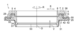
- FIG. 1 is a cross-sectional explanatory view taken along the line II of FIG. 2 showing a preferred example of an embodiment of the present invention.
- FIG. 2 is an explanatory plan view of the example shown in FIG.
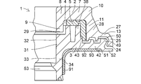
- FIG. 3 is a partially enlarged cross-sectional explanatory view of the example shown in FIG.
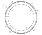
- FIG. 4 is an explanatory plan view of the upper case of the example shown in FIG.
- FIG. 5 is a cross-sectional explanatory view taken along the line VV of the upper case of the example shown in FIG.
- FIG. 6 is a partially enlarged cross-sectional explanatory view of the upper case of the example shown in FIG.
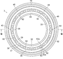
- FIG. 7 is an explanatory plan view of the lower case of the example shown in FIG.
- FIG. 8 is a cross-sectional explanatory view taken along the line VIII-VIII of the lower case of the example shown in FIG.
- FIG. 9 is a partially enlarged cross-sectional explanatory view of the lower case of the example shown in FIG.
- FIG. 10 is an enlarged plan explanatory view of the protrusion of the lower case in the example shown in FIG.
- FIG. 11 is an enlarged cross-sectional explanatory view of the elastic mounting portions of the upper case and the lower case in the example shown in FIG.
- FIG. 12 is an explanatory plan view of the slide bearing piece of the example shown in FIG. 13 is a cross-sectional explanatory view taken along the line XIII-XIII of the slide bearing piece of the example shown in FIG. FIG.
- FIG. 14 is an explanatory bottom view of the slide bearing piece of the example shown in FIG. 15 is a cross-sectional explanatory view taken along the line XVI-XVI of the slide bearing piece of the example shown in FIG.
- FIG. 16 is a partially enlarged cross-sectional explanatory view of the slide bearing piece of the example shown in FIG.
- FIG. 17 is a partially enlarged plan explanatory view of the slide bearing piece of the example shown in FIG.
- FIG. 18 is a partially enlarged plan explanatory view of the slide bearing of the example shown in FIG.
- FIG. 19 is an explanatory plan view of another embodiment of the sliding bearing piece of the example shown in FIG.
- FIG. 20 is a cross-sectional explanatory view taken along the line XX-XX of the slide bearing piece of the example shown in FIG.
- FIG. 21 is an explanatory plan view of the reinforcing member of the example shown in FIG. 22 is a cross-sectional explanatory view taken along the line XXII-XXII of the reinforcing member of the example shown in FIG.
- FIG. 23 is a partially enlarged cross-sectional explanatory view of the mounting portion for the lower case and the reinforcing member in the example shown in FIG. 1.
- 24 is a partially enlarged cross-sectional explanatory view of a mounting portion between the lower case and the flange portion of the reinforcing member in the example shown in FIG.
- FIG. 25 is a cross-sectional explanatory view in which the plain bearing shown in FIG. 1 is incorporated in a strut suspension.
- a synthetic resin sliding bearing 1 of this example for use in a strut suspension in a four-wheeled vehicle includes an upper case 2 made of synthetic resin fixed to a vehicle body via an attachment member, A synthetic resin lower case 3 superimposed on the upper case 2 so as to be rotatable in the circumferential direction R around the axis O with respect to the upper case 2, and a space between the upper case 2 and the lower case 3 4 and a sliding bearing piece 5 made of synthetic resin.
- the upper case 2 includes an annular upper case base 7 having an annular lower surface 6 in the axial direction, that is, the vertical direction Y, and a radial direction X of the upper case base 7.
- An inner peripheral cylindrical hanging portion 9 that hangs down from the inner peripheral end portion 8
- an outer peripheral cylindrical hanging portion 11 that hangs down from an outer peripheral end portion 10 in the radial direction X of the upper case base 7, and a lower end of the outer peripheral cylindrical hanging portion 11
- An annular flange 13 extending outward in the radial direction X from the portion 12, and a cylindrical inner peripheral surface 16 connected to the cylindrical inner peripheral surface 15 of the outer cylindrical hanging portion 11 from the annular lower surface 14 of the annular flange 13.
- An inclined surface portion 22 that gradually increases in diameter, and an engagement bulging portion 24 that is connected to the inclined surface portion 22 and that has an inclined surface portion 23 that gradually decreases inward in the radial direction X and bulges inward in the radial direction X.
- the engagement hanging portion 25 is provided.
- the reinforcing ribs 28 are reinforced by triangular reinforcing ribs 28 connected to the upper surface 27, and a plurality of reinforcing ribs 28 are formed along the circumferential direction R of the annular flange 13.
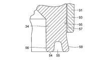
- the lower case 3 includes an annular lower case base 31 having an annular upper surface 29 and an annular lower surface 30 in the vertical direction Y, and an annular lower surface 30 of the lower case base 31 as shown in FIGS.
- a cylindrical protrusion 34 having a cylindrical inner peripheral surface 33 connected to the cylindrical inner peripheral surface 32 of the lower case base 31 and extending downward in the vertical direction Y, and an annular upper surface 29 of the lower case base 31 on the lower case base 31.
- a cylindrical outer peripheral surface 37 that protrudes upward in the vertical direction Y while leaving an annular shoulder 35 outward in the radial direction X and a cylindrical outer peripheral surface 37 that is connected to the cylindrical outer peripheral surface 36 of the lower case base 31.
- annular protrusion 45 that protrudes upward in the vertical direction Y by forming an inner peripheral lower annular recess 44 outward in the radial direction X, and an outer peripheral lower side outward of the annular protrusion 45 and radial direction X.
- An annular recess 46 is formed and protrudes upward in the vertical direction Y, and an outer peripheral surface thereof is inclined with respect to the annular upper surface 40 and gradually decreases in the radial direction X, and is connected to the inclined surface 47. It has an inclined surface portion 48 that gradually decreases in diameter toward the inner side in the radial direction X.
- An engagement protrusion 50 having an engaged bulge 49 to be engaged, and an annular plate shape extending outwardly in the radial direction X to the outer peripheral side lower end 51 of the annular flange 42 connected to the engagement protrusion 50 Part 52.
- annular protrusion 53 extending inward in the radial direction X is formed on the inner peripheral surface 33 of the cylinder.
- the annular protrusion 53 serves as a reinforcing rib that increases the crushing strength inward in the radial direction X of the cylindrical protrusion 34.
- the annular end surface 54 of the cylindrical projecting portion 34 is formed with an annular concave groove 55 that opens to the annular end surface 54, and the outer peripheral surface of the end portion 56 of the cylindrical projecting portion 34 in which the annular concave groove 55 is formed is cylindrically projected.
- the cylindrical projecting portion 34 formed on the annular tapered surface 58 is formed in an annular tapered surface 58 that gradually expands outward in the radial direction X downward in the vertical direction Y from the cylindrical outer peripheral surface 57 of the portion 34.
- the end portion 56 is provided with flexibility in the radial direction X.
- the annular lower surface 30 of the lower case base portion 31 and the annular lower surface 41 of the annular collar portion 42 are formed with a wide annular recess 59 connected to the cylindrical outer peripheral surface 57 of the cylindrical protrusion 34.
- a contact portion of the metal reinforcing member 93 is formed.
- the annular upper surface 60 of the annular protrusion 38 has a hole 62 having a bottom 61 that opens to the annular upper surface 60 and extends downward from the annular upper surface 60 to the lower case base 31 in the vertical direction Y.
- a plurality of lines are formed along the direction R.
- the hole 62 has an opening 63 having a rectangular shape in plan view, and is opposed to the longer side 63 a side of the opening 63 that gradually decreases in the vertical direction Y.
- An inclined surface 64 is provided.
- the upper case 2 and the lower case 3 are configured such that the engagement bulging portion 24 of the engagement hanging portion 25 of the upper case 2 is replaced with the engaged bulging portion 49 of the engagement protrusion 50 of the lower case 3. It is combined with elastic attachment. Since the engagement gap S of the elastic mounting portion is closed by the annular plate-like portion 52 extending outward in the radial direction X at the outer peripheral side lower end portion 51 of the annular collar portion 42, dust or the like from the engagement gap S Is prevented as much as possible.
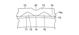
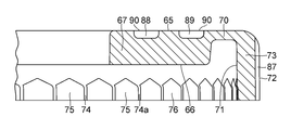
- the synthetic resin sliding bearing piece 5 disposed in the space 4 has an annular shape in the vertical direction Y that slidably contacts the annular lower surface 6 of the upper case base 7 as shown in FIGS. And an annular thrust sliding bearing piece 67 having an annular lower surface 66 that contacts the annular upper surface 60 of the annular projection 38 of the lower case base 31, and the radial direction X of the thrust sliding bearing piece 67 in the radial direction X.
- a radial slide having a cylindrical inner peripheral surface 71 and a cylindrical outer peripheral surface 72 hanging from an outer peripheral end 68 via an annular thin portion 70 having an annular upper surface 69 connected to the annular upper surface 65 of the thrust sliding bearing piece 67.
- a convex portion 74 having a triangular shape in a cross section and a concave portion 75 having a triangular shape in a cross section are provided in the circumferential direction R.
- the sliding bearing piece 5 has a circular shape around the axis O with respect to the lower case 3 by engaging the protrusions 43 and 43 formed on the cylindrical outer peripheral surface 36 of the lower case base 31 with the concave portion 75 of the concave and convex engaging portion 76. Since rotation in the circumferential direction R is blocked (prohibited) and integrated with the lower case 3, it does not slide between the sliding bearing piece 5 and the lower case 3.
- the uneven engagement portion 76 is formed over the entire circumference in the circumferential direction R of the cylindrical inner peripheral surface 71 of the radial sliding bearing piece portion 73, but the uneven engagement portion 76 corresponds to the protrusion 43. It may be formed only on the portion of the cylindrical inner peripheral surface 71 of the radial sliding bearing piece 73.
- the thrust slide bearing piece 67 has a plurality of inner recesses 77 and outer recesses 78 formed on the annular upper surface 65 along the circumferential direction R and in the radial direction X over at least two rows of the inner row and the outer row. is doing.
- Each of the plurality of inner concave portions 77 formed in the inner row has an inner arc-shaped wall surface 79 extending in an arc shape with the axis O as the center, and an axis extending outward in the radial direction X with respect to the inner arc-shaped wall surface 79.
- a pair of semicircular wall surfaces 81 connected to each other in the circumferential direction R, and a bottom wall surface 77a connected to each of the inner arcuate wall surface 79, the outer arcuate wall surface 80, and the pair of semicircular wall surfaces 81. It is prescribed by.
- Each of the plurality of outer recesses 78 formed in the outer row has an inner arc-shaped wall surface 82 extending in an arc shape with the axis O as the center, and an axis extending outward in the radial direction X with respect to the inner arc-shaped wall surface 82.
- the outer arc-shaped wall surface 83 that extends in the shape of an arc around the center O, that is, the inner arc-shaped wall surface 82 is expanded in the radial direction X, and the inner arc-shaped wall surface 82 and the outer arc-shaped wall surface 83 respectively.
- the ratio of the azo group is 20 to 50%, preferably 30 to 40%.
- the radial sliding bearing piece 73 has a plurality of axial grooves 87 that are open at both ends in the vertical direction Y and are formed on the cylindrical outer peripheral surface 72 at regular intervals in the circumferential direction R.
- the annular upper surface 65 of the thrust sliding bearing piece portion 67 extends along the circumferential direction R and in the radial direction X, the inner row and the outer row.
- the inner annular groove 88 and the outer annular groove 89 formed in two rows are formed, and are spaced apart at equal intervals in the circumferential direction R on the cylindrical outer peripheral surface 72 of the radial sliding bearing piece 73.
- a plurality of axial grooves 87 may be formed.
- An inner annular groove 88 and an outer annular groove 89 formed on the annular upper surface 65 of the thrust slide bearing piece 67 along the circumferential direction R and in the radial direction X in two rows of an inner row and an outer row are provided.
- the inner annular groove 88 occupying the total area of the opening surface 90 of the inner annular groove 88 and the outer annular groove 89 and the annular upper surface 65 of the thrust slide bearing piece 67 which is a thrust slide bearing surface, and
- the ratio of the total area of the opening surface 90 of the outer annular concave groove 89 is 20 to 50%, preferably 30 to 40%.
- the sliding bearing piece 5 brings the annular lower surface 66 of the thrust sliding bearing piece portion 67 into contact with the annular upper surface 60 of the annular protruding portion 38 of the lower case base 31, thereby causing radial sliding.
- the cylindrical inner peripheral surface 71 of the bearing piece 73 is brought into contact with the cylindrical inner peripheral surface 32 of the lower case base 31, and the protrusion of the lower case base 31 is projected into the concave portion 75 of the concave and convex engaging portion 76 of the cylindrical inner peripheral surface 32 of the lower case base 31.
- the portion 43 is engaged to prevent the lower case 3 from rotating in the circumferential direction R around the axis O, and is integrated with the lower case 3 and assembled to the lower case 3.
- the sliding bearing piece 5 assembled to the lower case 3 is slidably brought into contact with the annular upper surface 65 of the thrust sliding bearing piece 67 and the annular lower surface 6 of the upper case base 7 so as to be slidable.
- the upper case 2 is assembled by making the cylindrical inner peripheral surface 15 of the outer peripheral side cylindrical hanging portion 11 of the upper case base 7 slidably contact the 73 outer peripheral surface 72 of the upper case base 7.
- the thrust slide bearing piece 67 of the slide bearing piece 5 and the annular lower surface 6 of the upper case base 7 and the radial slide bearing piece 73 and the outer cylinder of the upper case base 7 are arranged.
- a sliding surface is formed only between the cylindrical inner peripheral surface 15 of the hanging portion 11, and the annular upper surface 65 of the thrust slide bearing piece 67 serving as the sliding surface is along the circumferential direction R and in the radial direction.
- a plurality of inner concave portions 77 and outer concave portions 78 or inner annular concave grooves 88 and outer annular concave grooves 89 are formed in X in two rows of the inner row and the outer row, and a radial sliding bearing serving as a sliding surface Since a plurality of axial grooves 87 are formed along the circumferential direction R on the cylindrical outer peripheral surface 72 of the piece 73, the annular upper surface 65 and the upper case base 7 of the thrust slide bearing piece 67 are formed.
- the surface pressure (load per unit area) acting on the cylindrical inner peripheral surface 15 of the side cylindrical hanging part 11 can be increased, the friction is reduced by the friction of synthetic resins, and the inner concave portion 77 and the outer concave portion 78 or the inner annular shape.
- a further reduction in friction can be achieved in combination with the reduction in friction caused by the lubricant filled in the concave groove 88, the outer annular concave groove 89 and the axial groove 90 on the sliding surface.
- a metal reinforcing member 93 having a cylindrical portion 91 and a wide annular flange 92 extending outward in the radial direction X at one end of the cylindrical portion 91 shown in FIGS. 21 to 24 is a wide annular shape.
- the surface 94 of the flange 92 is brought into contact with the annular lower surface 30 of the lower case base 31 and the annular lower surface 41 of the annular flange 42, and the cylindrical inner peripheral surface 95 of the cylindrical portion 91 is brought into contact with the cylindrical protrusion 34 of the lower case base 31.
- the lower case 3 is mounted by being inserted into the cylindrical outer peripheral surface 57.
- the annular lower surface 30 of the lower case base 31 of the lower case 3 serving as a spring seat of the suspension coil spring is reinforced by the reinforcing member 93.
- the end portion 56 of the cylindrical projecting portion 34 formed with the annular tapered surface 58 of the lower case base portion 31 is elastically deformed by the applied flexibility, and the reinforcing member 93.
- the cylindrical protrusion 34 of the lower case base 31 is easily fitted into the cylindrical outer peripheral surface 57. After the insertion, as shown in FIG. 24, the annular tapered surface of the end 56 of the cylindrical protrusion 34 is provided.
- the sliding bearing 1 formed in this way has the annular upper surface 7 a of the upper case 2 abutted against the mounting member 96 on the vehicle body side, and the spring is attached to the upper end portion of the suspension coil spring 97.
- the synthetic resin of this example is brought into contact with an annular lower surface 30 of the lower case base 31 as a seating surface or an annular flange 92 of a metal reinforcing member 93 attached to the annular lower surface 30 of the lower case base 31.
- the sliding bearing 1 made of the synthetic resin is disposed between the vehicle body side seating surface 98 of the mounting member 96 on the vehicle body side and the upper end of the suspension coil spring 97, and the sliding bearing 1 made of synthetic resin in this example is used as a strut for a four-wheeled vehicle. It may be applied to a mold suspension.
Landscapes
- Engineering & Computer Science (AREA)
- General Engineering & Computer Science (AREA)
- Mechanical Engineering (AREA)
- Sliding-Contact Bearings (AREA)
- Vehicle Body Suspensions (AREA)
- Fluid-Damping Devices (AREA)
Abstract
Description
2 上部ケース
3 下部ケース
4 空間
5 滑り軸受片
6 円環状下面
7 上部ケース基部
9 内周側円筒垂下部
11 外周側円筒垂下部
24 係合膨出部
25 係合垂下部
30 円環状下面
31 下部ケース基部
34 円筒突出部
38 円環状突出部
42 円環状鍔部
43 突起部
49 被係合膨出部
50 係合突出部
67 スラスト滑り軸受片部
73 ラジアル滑り軸受片部
74 凸部
75 凹部
76 凹凸噛合部
Claims (11)
- 合成樹脂製の上部ケースと、この上部ケースに対して軸心の回りで円周方向に回転自在となるように、当該上部ケースに重ね合わされている強化合成樹脂製の下部ケースと、上部ケース及び下部ケース間に配されている合成樹脂製の滑り軸受片とを具備しており、上部ケースは、上下方向において円環状下面を有した上部ケース基部と、この上部ケース基部の径方向の内周端部から垂下した内周側円筒垂下部と、上部ケース基部の径方向の外周端部から垂下した外周側円筒垂下部と、この外周側円筒垂下部の下端部から径方向の外方に伸びる円環状鍔部と、この円環状鍔部の円環状下面から外周側円筒垂下部の円筒内周面に連接する円筒内周面を有して下方に伸びる内側環状突条部と、この内側環状突条部と協働して径方向の外方に内周上側環状凹部を形成して円環状鍔部の円環状下面から下方に伸びる外側環状突条部と、この外側環状突条部と協働して径方向の内方に外周上側環状凹部を形成して円環状鍔部の外周縁部から垂下すると共に内周面に径方向の内方に膨出する係合膨出部を有した係合垂下部とを具備しており、下部ケースは、上下方向において円環状上面及び円環状下面を有した円環状の下部ケース基部と、この下部ケース基部の円環状下面から当該下部ケース基部の円筒内周面に連接する円筒内周面をもって下方に突出する円筒突出部と、下部ケース基部の円環状上面から上方に突出すると共に当該下部ケース基部の円筒外周面に連接する円筒外周面を有する円環状突出部と、下部ケース基部の円筒外周面の下端部から径方向の外方に伸びる円環状鍔部と、下部ケース基部の円筒外周面から径方向の外方に突出すると共に円環状鍔部の円環状上面から上方に伸びた少なくとも一つの突起部と、円環状鍔部の円環状上面から下部ケース基部の円筒外周面と協働して内周下側環状凹部を形成して上方に突出する環状突条部と、この環状突条部と協働して径方向の内方に外周下側環状凹部を形成して円環状鍔部の円環状上面から上方に突出すると共に外周面に径方向の外方に膨出する被係合膨出部を有した係合突出部と、円環状鍔部の外周側下端部から径方向の外方に伸びる環状板状部とを具備しており、滑り軸受片は、上下方向における円環状の上面及び円環状の下面を有する円環状のスラスト滑り軸受片部と、このスラスト滑り軸受片部の外周端部から垂下すると共に円筒内周面及び円筒外周面を有した円筒状のラジアル滑り軸受片部と、このラジアル滑り軸受片部の円筒内周面の下端部に円周方向に沿って交互に形成された凸部及び凹部を有した凹凸噛合部とを備えており、滑り軸受片は、スラスト滑り軸受片部の円環状の下面を下部ケースの円環状突出部の円環状上面に接触させ、ラジアル滑り軸受片部の円筒内周面を下部ケースの円環状突出部の円筒内周面に接触させると共に下部ケースに対しての軸心の回りでの回転が禁止されるように、凹凸噛合部の凹部を下部ケースの突起部に噛合させて、上部ケース及び下部ケース間に配されており、上部ケースは、上部ケース基部の円環状下面をスラスト滑り軸受片部の円環状の上面に摺動自在に接触させると共に外周側円筒垂下部の円筒内周面をラジアル滑り軸受片部の円筒外周面に摺動自在に接触させ、内側環状突条部を下部ケースの内周下側環状凹部に、及び外側環状突条部を下部ケースの外周下側環状凹部に夫々臨ませると共に、係合垂下部の係合膨出部を下部ケースの係合突出部の被係合膨出部に弾性装着させて下部ケースに組み合わされていることを特徴とする合成樹脂製の滑り軸受。
- 下部ケース基部及びこの下部ケース基部の円環状下面から下方に突出する円筒突出部は、当該円筒突出部の円筒外周面に嵌挿された円筒部とこの円筒部の一方の端部に一体的に形成されていると共に下部ケース基部の円環状下面に接触した環状鍔部とを有した金属製の補強部材によって補強されている請求項1に記載の合成樹脂製の滑り軸受。
- 円筒突出部の環状端面には、環状凹溝が形成されており、この環状凹溝が形成された円筒突出部の円筒外周面の端部外周面は、当該端部外周面を除く円筒突出部の円筒外周面よりも径方向の外方に円筒突出部の環状端面に向かうに連れて漸次拡がる環状テーパ面として形成されており、円筒突出部の円筒外周面に嵌挿された補強部材は、円筒部において円筒突出部の環状テーパ面として形成された端部外周面が円筒部の下端面側で径方向の外方に突出することにより、下方向に抜け止めされている請求項1又は2に記載の合成樹脂製の滑り軸受。
- スラスト滑り軸受片部は、その円環状の上面に円周方向に沿うと共に径方向に少なくとも内側列と外側列の二列にわたって形成された複数個の内側凹部及び外側凹部を有しており、内側凹部と外側凹部とは、互に円周方向に位相差をもって配列されており、ラジアル軸受片部は、上下方向において開口していると共にその円筒外周面に円周方向に等間隔に離間して形成された複数個の軸方向溝を有している請求項1から3のいずれか一項に記載の合成樹脂製の滑り軸受。
- 複数個の内側凹部の夫々は、軸心を中心として円弧状に伸びた内側円弧状壁面と、該内側円弧状壁面に対して径方向外方で軸心を中心として円弧状に伸びた外側円弧状壁面と、内側円弧状壁面及び外側円弧状壁面の夫々に連接されていると共に互いに円周方向において対面する一対の半円状壁面と、該内側円弧状壁面、外側円弧状壁面及び底一対の半円状壁面の夫々に連接された底壁面とによって規定されている請求項4に記載の合成樹脂製の滑り軸受。
- 複数個の外側凹部の夫々は、軸心を中心として円弧状に伸びた内側円弧状壁面と、該内側円弧状壁面に対して径方向外方で軸心を中心として円弧状に伸びた外側円弧状壁面と、内側円弧状壁面及び外側円弧状壁面の夫々に連接されていると共に互いに円周方向において対面する一対の半円状壁面と、該内側円弧状壁面、外側円弧状壁面及び底一対の半円状壁面の夫々に連接された底壁面とによって規定されている請求項4又は5に記載の合成樹脂製の滑り軸受。
- 複数個の内側凹部及び外側凹部の開口面とスラスト滑り軸受片部の円環状の上面とを合わせた面に占める複数個の内側凹部及び外側凹部の開口面の総面積の割合は、20~50%である請求項4から6のいずれか一項に記載の合成樹脂製の滑り軸受。
- スラスト滑り軸受片は、その円環状の上面に円周方向に沿うと共に互いに同心に形成された少なくとも内側列と外側列の二列にわたって形成された円環状凹溝を有している請求項1から3のいずれか一項に記載の合成樹脂製の滑り軸受。
- 円環状凹溝の開口面とスラスト滑り軸受片部の円環状の上面とを合わせた面に占める少なくとも2個の円環状凹溝の開口面の総面積の割合は、20~50%である請求項8に記載の合成樹脂製の滑り軸受。
- スラスト滑り軸受片は、その円環状の上面に円周方向に沿うと共に互いに同心に形成された少なくとも内側列と外側列の二列にわたって形成された円環状凹溝を有している請求項4から7のいずれか一項に記載の合成樹脂製の滑り軸受。
- 複数個の内側凹部及び外側凹部の開口面と円環状凹溝の開口面とスラスト滑り軸受片部の円環状の上面とを合わせた面に占める複数個の内側凹部及び外側凹部の開口面並びに少なくとも2個の円環状凹溝の開口面の総面積の割合は、20~50%である請求項10に記載の合成樹脂製の滑り軸受。
Priority Applications (7)
| Application Number | Priority Date | Filing Date | Title |
|---|---|---|---|
| EP18180513.6A EP3404276B1 (en) | 2013-02-15 | 2014-02-04 | Synthetic resin plain bearing |
| KR1020157021759A KR101698048B1 (ko) | 2013-02-15 | 2014-02-04 | 합성 수지제 슬라이딩 베어링 |
| US14/767,700 US9539874B2 (en) | 2013-02-15 | 2014-02-04 | Synthetic resin-made sliding bearing |
| CN201480008885.8A CN104995419B (zh) | 2013-02-15 | 2014-02-04 | 合成树脂制滑动轴承 |
| BR112015018786-2A BR112015018786B1 (pt) | 2013-02-15 | 2014-02-04 | Mancal deslizante de resina sintética |
| EP14751056.4A EP2957783B1 (en) | 2013-02-15 | 2014-02-04 | Synthetic resin plain bearing |
| US15/363,057 US9707816B2 (en) | 2013-02-15 | 2016-11-29 | Synthetic resin-made sliding bearing |
Applications Claiming Priority (2)
| Application Number | Priority Date | Filing Date | Title |
|---|---|---|---|
| JP2013028455A JP6322889B2 (ja) | 2013-02-15 | 2013-02-15 | 合成樹脂製の滑り軸受 |
| JP2013-028455 | 2013-02-15 |
Related Child Applications (2)
| Application Number | Title | Priority Date | Filing Date |
|---|---|---|---|
| US14/767,700 A-371-Of-International US9539874B2 (en) | 2013-02-15 | 2014-02-04 | Synthetic resin-made sliding bearing |
| US15/363,057 Continuation US9707816B2 (en) | 2013-02-15 | 2016-11-29 | Synthetic resin-made sliding bearing |
Publications (1)
| Publication Number | Publication Date |
|---|---|
| WO2014125788A1 true WO2014125788A1 (ja) | 2014-08-21 |
Family
ID=51353803
Family Applications (1)
| Application Number | Title | Priority Date | Filing Date |
|---|---|---|---|
| PCT/JP2014/000592 WO2014125788A1 (ja) | 2013-02-15 | 2014-02-04 | 合成樹脂製の滑り軸受 |
Country Status (7)
| Country | Link |
|---|---|
| US (2) | US9539874B2 (ja) |
| EP (2) | EP2957783B1 (ja) |
| JP (1) | JP6322889B2 (ja) |
| KR (1) | KR101698048B1 (ja) |
| CN (2) | CN106958592B (ja) |
| BR (1) | BR112015018786B1 (ja) |
| WO (1) | WO2014125788A1 (ja) |
Cited By (1)
| Publication number | Priority date | Publication date | Assignee | Title |
|---|---|---|---|---|
| US10422374B2 (en) | 2015-11-20 | 2019-09-24 | Oiles Corporation | Synthetic resin-made sliding bearing |
Families Citing this family (5)
| Publication number | Priority date | Publication date | Assignee | Title |
|---|---|---|---|---|
| JP6602042B2 (ja) * | 2015-04-28 | 2019-11-06 | オイレス工業株式会社 | 滑り軸受 |
| DE102017129123B4 (de) * | 2017-12-07 | 2019-10-17 | Schaeffler Technologies AG & Co. KG | Abgedichtetes Wälzlager und Verfahren zum Betrieb eines Wälzlagers |
| KR102062876B1 (ko) * | 2018-04-13 | 2020-01-06 | 이상욱 | 차량 현가장치용 코일스프링 지지대 |
| FR3108064B1 (fr) * | 2020-03-10 | 2022-06-24 | Ntn Snr Roulements | Butée de suspension de véhicule automobile |
| KR20240010330A (ko) * | 2022-07-15 | 2024-01-23 | 주식회사 일진 | 차량용 스트럿 베어링 어셈블리 |
Citations (5)
| Publication number | Priority date | Publication date | Assignee | Title |
|---|---|---|---|---|
| JPH01100922U (ja) * | 1987-12-25 | 1989-07-06 | ||
| JP2001027229A (ja) * | 1999-07-15 | 2001-01-30 | Oiles Ind Co Ltd | 合成樹脂製の滑り軸受 |
| JP2004293589A (ja) | 2003-03-25 | 2004-10-21 | Oiles Ind Co Ltd | ストラット滑り軸受 |
| JP2009250278A (ja) | 2008-04-02 | 2009-10-29 | Oiles Ind Co Ltd | スラスト滑り軸受 |
| US20100040317A1 (en) * | 2008-08-13 | 2010-02-18 | Schaeffler Kg | Sliding strut bearing |
Family Cites Families (19)
| Publication number | Priority date | Publication date | Assignee | Title |
|---|---|---|---|---|
| JP2538944B2 (ja) | 1987-10-14 | 1996-10-02 | 富士通株式会社 | ドライエッチング装置 |
| JP2600937Y2 (ja) * | 1993-11-30 | 1999-11-02 | オイレス工業株式会社 | 合成樹脂軸受 |
| JP3709939B2 (ja) * | 1995-08-31 | 2005-10-26 | オイレス工業株式会社 | 合成樹脂軸受 |
| JP4419217B2 (ja) * | 1999-07-15 | 2010-02-24 | オイレス工業株式会社 | 合成樹脂製の滑り軸受 |
| JP3988397B2 (ja) * | 2001-02-27 | 2007-10-10 | オイレス工業株式会社 | 合成樹脂製の滑り軸受 |
| JP4061939B2 (ja) * | 2002-03-26 | 2008-03-19 | オイレス工業株式会社 | 複層滑り軸受及びその製造方法 |
| US6929402B1 (en) * | 2002-04-11 | 2005-08-16 | Morgan Construction Company | Journal bearing and thrust pad assembly |
| JP2004225863A (ja) * | 2003-01-27 | 2004-08-12 | Marugo Rubber Ind Co Ltd | 樹脂製摺動軸受 |
| JP4366946B2 (ja) * | 2003-02-07 | 2009-11-18 | オイレス工業株式会社 | スラスト滑り軸受 |
| JP2006322507A (ja) * | 2005-05-18 | 2006-11-30 | Jtekt Corp | スラスト軸受 |
| JP2008014463A (ja) * | 2006-07-07 | 2008-01-24 | Oiles Ind Co Ltd | スラスト滑り軸受及びこのスラスト滑り軸受とピストンロッドとの組合せ機構 |
| JP2008232174A (ja) * | 2007-03-16 | 2008-10-02 | Jtekt Corp | サスペンション用軸受 |
| JP5157210B2 (ja) * | 2007-03-20 | 2013-03-06 | オイレス工業株式会社 | スラスト滑り軸受並びにこのスラスト滑り軸受とピストンロッド及びコイルばねとの組合せ機構 |
| JP5245508B2 (ja) | 2008-04-18 | 2013-07-24 | オイレス工業株式会社 | スラスト滑り軸受 |
| JP5516210B2 (ja) | 2010-08-06 | 2014-06-11 | オイレス工業株式会社 | スラスト滑り軸受 |
| JP5673110B2 (ja) * | 2011-01-07 | 2015-02-18 | オイレス工業株式会社 | スラスト滑り軸受及びこのスラスト滑り軸受を用いたストラット型サスペンションの取付構造 |
| JP5444270B2 (ja) | 2011-02-23 | 2014-03-19 | オイレス工業株式会社 | 合成樹脂製のスラスト滑り軸受 |
| JP5906590B2 (ja) | 2011-06-09 | 2016-04-20 | オイレス工業株式会社 | 合成樹脂製の滑り軸受 |
| JP5842402B2 (ja) | 2011-06-20 | 2016-01-13 | オイレス工業株式会社 | スラスト滑り軸受 |
-
2013
- 2013-02-15 JP JP2013028455A patent/JP6322889B2/ja active Active
-
2014
- 2014-02-04 WO PCT/JP2014/000592 patent/WO2014125788A1/ja active Application Filing
- 2014-02-04 EP EP14751056.4A patent/EP2957783B1/en active Active
- 2014-02-04 CN CN201710326079.0A patent/CN106958592B/zh active Active
- 2014-02-04 CN CN201480008885.8A patent/CN104995419B/zh active Active
- 2014-02-04 KR KR1020157021759A patent/KR101698048B1/ko active IP Right Grant
- 2014-02-04 BR BR112015018786-2A patent/BR112015018786B1/pt active IP Right Grant
- 2014-02-04 EP EP18180513.6A patent/EP3404276B1/en active Active
- 2014-02-04 US US14/767,700 patent/US9539874B2/en active Active
-
2016
- 2016-11-29 US US15/363,057 patent/US9707816B2/en active Active
Patent Citations (5)
| Publication number | Priority date | Publication date | Assignee | Title |
|---|---|---|---|---|
| JPH01100922U (ja) * | 1987-12-25 | 1989-07-06 | ||
| JP2001027229A (ja) * | 1999-07-15 | 2001-01-30 | Oiles Ind Co Ltd | 合成樹脂製の滑り軸受 |
| JP2004293589A (ja) | 2003-03-25 | 2004-10-21 | Oiles Ind Co Ltd | ストラット滑り軸受 |
| JP2009250278A (ja) | 2008-04-02 | 2009-10-29 | Oiles Ind Co Ltd | スラスト滑り軸受 |
| US20100040317A1 (en) * | 2008-08-13 | 2010-02-18 | Schaeffler Kg | Sliding strut bearing |
Cited By (1)
| Publication number | Priority date | Publication date | Assignee | Title |
|---|---|---|---|---|
| US10422374B2 (en) | 2015-11-20 | 2019-09-24 | Oiles Corporation | Synthetic resin-made sliding bearing |
Also Published As
| Publication number | Publication date |
|---|---|
| CN106958592A (zh) | 2017-07-18 |
| EP2957783A4 (en) | 2016-10-19 |
| US9707816B2 (en) | 2017-07-18 |
| US9539874B2 (en) | 2017-01-10 |
| BR112015018786B1 (pt) | 2020-12-15 |
| EP2957783A1 (en) | 2015-12-23 |
| CN104995419B (zh) | 2017-05-31 |
| US20170072759A1 (en) | 2017-03-16 |
| US20150375591A1 (en) | 2015-12-31 |
| JP6322889B2 (ja) | 2018-05-16 |
| EP3404276B1 (en) | 2020-06-17 |
| BR112015018786A2 (pt) | 2017-07-18 |
| KR20150104208A (ko) | 2015-09-14 |
| CN104995419A (zh) | 2015-10-21 |
| EP3404276A1 (en) | 2018-11-21 |
| KR101698048B1 (ko) | 2017-01-19 |
| JP2014156907A (ja) | 2014-08-28 |
| EP2957783B1 (en) | 2018-08-15 |
| CN106958592B (zh) | 2019-03-12 |
Similar Documents
| Publication | Publication Date | Title |
|---|---|---|
| JP6194586B2 (ja) | 合成樹脂製の滑り軸受 | |
| JP6017340B2 (ja) | 合成樹脂製の滑り軸受 | |
| JP6057814B2 (ja) | 合成樹脂製の滑り軸受 | |
| JP5332379B2 (ja) | 合成樹脂製スラスト滑り軸受 | |
| JP5910000B2 (ja) | 合成樹脂製の滑り軸受 | |
| WO2014125788A1 (ja) | 合成樹脂製の滑り軸受 | |
| JP5909976B2 (ja) | 合成樹脂製の滑り軸受 | |
| JP6631648B2 (ja) | 合成樹脂製の滑り軸受 | |
| JP6211124B2 (ja) | 合成樹脂製の滑り軸受 | |
| WO2016163445A1 (ja) | 車両用スラスト軸受 |
Legal Events
| Date | Code | Title | Description |
|---|---|---|---|
| 121 | Ep: the epo has been informed by wipo that ep was designated in this application |
Ref document number: 14751056 Country of ref document: EP Kind code of ref document: A1 |
|
| WWE | Wipo information: entry into national phase |
Ref document number: 2014751056 Country of ref document: EP |
|
| ENP | Entry into the national phase |
Ref document number: 20157021759 Country of ref document: KR Kind code of ref document: A |
|
| WWE | Wipo information: entry into national phase |
Ref document number: 14767700 Country of ref document: US |
|
| NENP | Non-entry into the national phase |
Ref country code: DE |
|
| REG | Reference to national code |
Ref country code: BR Ref legal event code: B01A Ref document number: 112015018786 Country of ref document: BR |
|
| ENP | Entry into the national phase |
Ref document number: 112015018786 Country of ref document: BR Kind code of ref document: A2 Effective date: 20150805 |