WO2014125699A1 - 落雷抑制型避雷装置 - Google Patents
落雷抑制型避雷装置 Download PDFInfo
- Publication number
- WO2014125699A1 WO2014125699A1 PCT/JP2013/082229 JP2013082229W WO2014125699A1 WO 2014125699 A1 WO2014125699 A1 WO 2014125699A1 JP 2013082229 W JP2013082229 W JP 2013082229W WO 2014125699 A1 WO2014125699 A1 WO 2014125699A1
- Authority
- WO
- WIPO (PCT)
- Prior art keywords
- lightning
- electrode body
- insulator
- lower electrode
- cylindrical insulator
- Prior art date
- Legal status (The legal status is an assumption and is not a legal conclusion. Google has not performed a legal analysis and makes no representation as to the accuracy of the status listed.)
- Ceased
Links
Images

Classifications
-
- H—ELECTRICITY
- H01—ELECTRIC ELEMENTS
- H01T—SPARK GAPS; OVERVOLTAGE ARRESTERS USING SPARK GAPS; SPARKING PLUGS; CORONA DEVICES; GENERATING IONS TO BE INTRODUCED INTO NON-ENCLOSED GASES
- H01T4/00—Overvoltage arresters using spark gaps
- H01T4/02—Details
-
- H—ELECTRICITY
- H01—ELECTRIC ELEMENTS
- H01T—SPARK GAPS; OVERVOLTAGE ARRESTERS USING SPARK GAPS; SPARKING PLUGS; CORONA DEVICES; GENERATING IONS TO BE INTRODUCED INTO NON-ENCLOSED GASES
- H01T4/00—Overvoltage arresters using spark gaps
- H01T4/10—Overvoltage arresters using spark gaps having a single gap or a plurality of gaps in parallel
Definitions
- the present invention relates to a lightning-suppressing lightning arrester for protecting a protected object such as a building or equipment from lightning damage by suppressing lightning.
- Lightning strike is a discharge phenomenon that occurs in the atmosphere.
- Lightning discharge includes in-cloud discharge, cloud-to-cloud discharge, cloud-to-ground discharge, and the like. It is the cloud-to-ground discharge (hereinafter referred to as lightning strike) that causes significant damage from lightning discharge.
- a lightning strike is a phenomenon that occurs when the electric field strength between a thundercloud (cloud bottom) and a structure constructed on the earth or ground becomes very large, and its charge is saturated to break the insulation of the atmosphere. is there.
- the deionization capacity type lightning rod (PDCE) described in Patent Document 2 is a lightning strike suppression type lightning rod, which is less likely to generate an upward streamer. For this reason, lightning strikes are unlikely to occur at facilities where the PDCE is installed at the highest part.
- This PDCE has an upper electrode body and a lower electrode body arranged with an insulator interposed therebetween, and only the lower electrode body is grounded. Therefore, for example, when a thundercloud with negative charges distributed at the bottom of the cloud approaches, the opposite charge (plus charge) is distributed on the surface of the earth, attracted by the positive charge at the bottom of the cloud, and positive charges are also charged to the lower electrode body. Get together. Then, the upper electrode body arranged via the insulator is negatively charged by the action of the capacitor. This action makes it difficult to generate upward streamers in the PDCE and its surroundings, and suppresses the occurrence of lightning strikes.
- the present inventors have found that the suppression effect can be increased by increasing the insulation between the upper and lower electrode bodies of the PDCE while studying the mechanism of summer thunder suppression by the PDCE. Yes.
- a lightning suppression type lightning arrester includes a lightning pole member having an insulator that insulates an upper electrode body and a lower electrode body, and a support member provided below the lightning pole member.
- the insulator includes a cylindrical insulator disposed between the upper electrode body and the lower electrode body, and a cover member disposed around the cylindrical insulator, and the cylindrical insulator is It is characterized by being formed of fine ceramic.
- the cylindrical insulator by forming the cylindrical insulator with fine ceramic, not only can the required insulation performance be sufficiently ensured, but also the mechanical strength and thermal shock resistance are ensured, The soundness of the lightning suppression type lightning arrester can be ensured.
- a lightning-suppressing lightning arrester is characterized in that the cylindrical insulator according to claim 1 is provided in an annular groove formed on each of opposing surfaces of the upper electrode body and the lower electrode body.
- the upper electrode body and the lower electrode body are connected by being fitted together, and the peripheral wall of the cylindrical insulator is provided with a vent hole penetrating in the thickness direction of the peripheral wall. It is characterized by being.
- a lightning-reducing lightning arrester according to claim 3 of the present invention is such that the tubular insulator according to claim 2 is fixed to the upper electrode body and the lower electrode body with a heat-resistant inorganic adhesive. It is characterized by that.
- the mechanical connection strength between the two electrode bodies and the cylindrical insulator can be increased, and a decrease in the connection strength due to a thermal change can be suppressed. Can prevent damage.
- the present invention while ensuring the insulation performance of the cylindrical insulator connecting the upper and lower electrode bodies, the mechanical strength and the strength against thermal shock are ensured, and the soundness of the lightning suppression type lightning arrester against lightning strikes is improved. Can be secured.
- FIG. 1 is a view showing an embodiment in which the present invention is applied to a deionization capacity type lightning rod, and a characteristic portion is shown in cross section.
- a lightning suppression lightning arrester A includes a lightning pole member 1 disposed at the top, a connecting member 2 provided at a lower portion of the lightning pole member 1, and the connecting member. And a support member 3 that is connected vertically through 2 to support the lightning pole member 1.
- the lightning pole member 1 includes an upper electrode body 11, a lower electrode body 12, and an insulator 13 provided between the upper electrode body 11 and the lower electrode body 12, and is formed in a substantially spherical shape as a whole. .
- the upper electrode body 11 and the lower electrode body 12 are formed in a slightly flat hemispherical shape in which a sphere is divided in half. Therefore, those surfaces are formed as curved surface portions 11a and 12a that come into contact with the atmosphere.
- the upper electrode body 11 and the lower electrode body 12 are formed in a cavity as illustrated. Further, a downward convex portion 11 b and an upward convex portion 12 b facing each other from the top surface of the upper electrode body 11 and the inner bottom surface of the lower electrode body 12 are formed.
- the interval H1 is set so that the downward convex portion 11b and the upward convex portion 12b exhibit a function as a discharging convex portion.
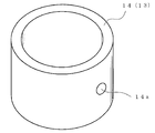
- the insulator 13 includes a cylindrical insulator 14 disposed between the upper electrode body 11 and the lower electrode body 12, and a cover member 15 disposed around the cylindrical insulator 14.
- the cylindrical insulator 14 is formed into a thick cylindrical shape by a fine ceramic formed by compacting and then firing 99.6% powder of alumina, and each end is connected to the upper electrode body 11. It fits in the annular grooves 11c and 12c formed in each of the opposing surfaces of the lower electrode body 12, and is integrated with an adhesive. Thus, the upper electrode body 11 and the lower electrode body 12 are connected in a liquid-tight and air-tight manner by the cylindrical insulator 14.
- peripheral wall of the cylindrical insulator 14 is provided with a vent hole 14a penetrating in the thickness direction of the peripheral wall in the peripheral wall portion of the intermediate portion in the length direction.
- the cover member 15 is made of fluororubber, and has an annular base portion 15a disposed so as to surround the outer periphery of the cylindrical insulator 14, and a continuous outer periphery of the base portion 15a. And a skirt portion 15 b that extends outward from both the electrode bodies 11 and 12 and covers a side portion of the lower electrode body 12.
- the cover member 15 When the pressure in the space S formed by the upper and lower electrode bodies 11 and 12 and the cylindrical insulator 14 rises, the cover member 15 allows the air in the space A to pass through. The compressed air is elastically deformed by acting through the hole 14a, and the compressed air is discharged to the outside through a gap with the cylindrical insulator 14.
- the upper electrode body 11, the lower electrode body 12, the connecting member 2, and the support member 3 are made of stainless steel having high conductivity.
- the support member 3 includes a support rod 31 located at the center and a support pipe 32 arranged coaxially on the outside thereof, and the support rod 31 is formed with a screw portion 31a.
- the support rod 31 has one end portion (upper end portion in the drawing) screwed to the lower electrode body 12 by the screw portion 31a and a nut 33 screwed to the screw portion 31a.
- the lower electrode body 12 and the support rod 31 are integrated by being pressed against the lower electrode body 12.
- a fixing nut 34 that presses the connecting member 2 against the lower surface of the lower electrode body 12 is screwed to the screw portion 31 a of the support rod 31.
- the lower end portion of the support rod 31 is positioned so as to protrude from the lower end of the support pipe 32 disposed so as to surround the support rod 31, and a mounting plate 35 is attached to the protruded portion. ing.
- the mounting plate 35 is pressed and fixed to the support pipe 32 by double nuts 36 and 36 that are screwed into a screw portion 31 a formed on the support rod 31.
- the lower electrode body 12 is electrically connected to the ground via the support member 3 and a grounding conductor (ground wire) (not shown).
- ground wire ground wire
- the maximum usable temperature of the fine ceramic constituting the cylindrical insulator 14 is as high as 1500 ° C., and the tensile strength is as large as 25 kg / mm 2 . As a result, the strength of the cylindrical insulator 14 connecting the two electrode bodies 11 and 12 is sufficiently secured.
- the cylindrical insulator 14 is made of a fine ceramic having no carbon group, no soot is generated when the temperature rises to a high temperature. Can do.
- the soundness of the lightning-suppressing type lightning arrester A also depends on the connection strength between the electrode bodies 11 and 12 and the cylindrical insulator 14.
- connection between the electrode bodies 11 and 12 and the cylindrical insulator 14 is performed by bonding with a heat-resistant inorganic adhesive, the bonding strength is sufficiently high even at high temperatures. It is ensured and the above-mentioned soundness is ensured.
- cover member 15 Furthermore, by forming the cover member 15 from fluoro rubber, environmental resistance such as aging resistance, weather resistance, ozone resistance, and flame resistance is ensured.
- the product number FC-2186 manufactured by Sumitomo 3M Co. was used as the fluororubber, and this fluororubber was held at a temperature of 300 ° C. for 1 hour and then returned to room temperature. There was no change in weight, no change in elasticity, and no discoloration or cracking.
Landscapes
- Elimination Of Static Electricity (AREA)
Applications Claiming Priority (2)
| Application Number | Priority Date | Filing Date | Title |
|---|---|---|---|
| JP2013-025766 | 2013-02-13 | ||
| JP2013025766A JP5757025B2 (ja) | 2013-02-13 | 2013-02-13 | 落雷抑制型避雷装置 |
Publications (1)
| Publication Number | Publication Date |
|---|---|
| WO2014125699A1 true WO2014125699A1 (ja) | 2014-08-21 |
Family
ID=51353718
Family Applications (1)
| Application Number | Title | Priority Date | Filing Date |
|---|---|---|---|
| PCT/JP2013/082229 Ceased WO2014125699A1 (ja) | 2013-02-13 | 2013-11-29 | 落雷抑制型避雷装置 |
Country Status (2)
| Country | Link |
|---|---|
| JP (1) | JP5757025B2 (enExample) |
| WO (1) | WO2014125699A1 (enExample) |
Cited By (2)
| Publication number | Priority date | Publication date | Assignee | Title |
|---|---|---|---|---|
| CN106028612A (zh) * | 2015-03-24 | 2016-10-12 | 丁特科国际公司 | 可变电场平衡装置 |
| CN116151034A (zh) * | 2023-04-17 | 2023-05-23 | 广东电网有限责任公司揭阳供电局 | 一种绝缘子芯棒酥化的预测方法、装置、设备及介质 |
Citations (5)
| Publication number | Priority date | Publication date | Assignee | Title |
|---|---|---|---|---|
| JPH01140718U (enExample) * | 1988-03-18 | 1989-09-27 | ||
| JP2004039472A (ja) * | 2002-07-04 | 2004-02-05 | Energy Support Corp | 開閉器 |
| JP2010205687A (ja) * | 2009-03-06 | 2010-09-16 | Sankosha Corp | 避雷装置 |
| JP2012182035A (ja) * | 2011-03-02 | 2012-09-20 | Lightning Suppression Systems Co Ltd | 落雷抑制型避雷装置 |
| JP2013196977A (ja) * | 2012-03-21 | 2013-09-30 | Lightning Suppression Systems Co Ltd | 落雷抑制型避雷装置 |
-
2013
- 2013-02-13 JP JP2013025766A patent/JP5757025B2/ja active Active
- 2013-11-29 WO PCT/JP2013/082229 patent/WO2014125699A1/ja not_active Ceased
Patent Citations (5)
| Publication number | Priority date | Publication date | Assignee | Title |
|---|---|---|---|---|
| JPH01140718U (enExample) * | 1988-03-18 | 1989-09-27 | ||
| JP2004039472A (ja) * | 2002-07-04 | 2004-02-05 | Energy Support Corp | 開閉器 |
| JP2010205687A (ja) * | 2009-03-06 | 2010-09-16 | Sankosha Corp | 避雷装置 |
| JP2012182035A (ja) * | 2011-03-02 | 2012-09-20 | Lightning Suppression Systems Co Ltd | 落雷抑制型避雷装置 |
| JP2013196977A (ja) * | 2012-03-21 | 2013-09-30 | Lightning Suppression Systems Co Ltd | 落雷抑制型避雷装置 |
Cited By (4)
| Publication number | Priority date | Publication date | Assignee | Title |
|---|---|---|---|---|
| CN106028612A (zh) * | 2015-03-24 | 2016-10-12 | 丁特科国际公司 | 可变电场平衡装置 |
| CN106028612B (zh) * | 2015-03-24 | 2020-07-24 | 丁特科国际公司 | 可变电场平衡装置 |
| CN116151034A (zh) * | 2023-04-17 | 2023-05-23 | 广东电网有限责任公司揭阳供电局 | 一种绝缘子芯棒酥化的预测方法、装置、设备及介质 |
| CN116151034B (zh) * | 2023-04-17 | 2023-06-27 | 广东电网有限责任公司揭阳供电局 | 一种绝缘子芯棒酥化的预测方法、装置、设备及介质 |
Also Published As
| Publication number | Publication date |
|---|---|
| JP5757025B2 (ja) | 2015-07-29 |
| JP2014154502A (ja) | 2014-08-25 |
Similar Documents
| Publication | Publication Date | Title |
|---|---|---|
| JP5780567B1 (ja) | 落雷抑制型避雷装置 | |
| JP6885593B2 (ja) | 落雷抑制型避雷器および避雷装置 | |
| JP5839331B1 (ja) | 落雷抑制型避雷装置 | |
| CN101098072A (zh) | 避雷装置 | |
| JP5443410B2 (ja) | 落雷抑制型避雷装置 | |
| JP5757025B2 (ja) | 落雷抑制型避雷装置 | |
| JP5780552B2 (ja) | 落雷抑制型避雷装置 | |
| JP2016081889A (ja) | 落雷抑制型避雷装置 | |
| EP3531803B1 (en) | Lighting-strike-suppression-type lightning protection device and lighting arrester | |
| CN110100504B (zh) | 落雷抑制型避雷装置 | |
| JP5757491B1 (ja) | 落雷抑制型避雷装置 | |
| JP6934668B2 (ja) | 落雷抑制型避雷器及び落雷抑制型避雷装置 | |
| JP5780566B1 (ja) | 落雷抑制型避雷装置 | |
| JP6128539B1 (ja) | 落雷抑制型避雷装置 | |
| JP6347340B1 (ja) | 落雷抑制型避雷装置及び避雷器 | |
| KR100998316B1 (ko) | 전기 쌍극자 방식과 방전 유도 기능을 이용한 정전분산 공간전하의 다량의 스트리머 방출 피뢰침 | |
| JP6028293B1 (ja) | 落雷抑制型避雷装置 | |
| JP6128542B1 (ja) | 落雷抑制型避雷装置 | |
| JP2018081801A (ja) | 落雷抑制型避雷装置 | |
| JP2018078087A (ja) | 保護機能付き抑制型避雷装置 | |
| CN204884738U (zh) | 一种配电变电站用避雷器 | |
| JP6356311B1 (ja) | 落雷制御装置 | |
| JP5780554B2 (ja) | 落雷抑制型避雷装置 | |
| JP2013191394A (ja) | 避雷装置 | |
| JP4169126B2 (ja) | ギャップ付きアレスタ |
Legal Events
| Date | Code | Title | Description |
|---|---|---|---|
| 121 | Ep: the epo has been informed by wipo that ep was designated in this application |
Ref document number: 13875234 Country of ref document: EP Kind code of ref document: A1 |
|
| NENP | Non-entry into the national phase |
Ref country code: DE |
|
| 32PN | Ep: public notification in the ep bulletin as address of the adressee cannot be established |
Free format text: NOTING OF LOSS OF RIGHTS PURSUANT TO RULE 112(1) EPC , EPO FORM 1205A DATED 19.01.16 |
|
| 122 | Ep: pct application non-entry in european phase |
Ref document number: 13875234 Country of ref document: EP Kind code of ref document: A1 |