WO2014125699A1 - Lightning suppression type lightning protection device - Google Patents
Lightning suppression type lightning protection device Download PDFInfo
- Publication number
- WO2014125699A1 WO2014125699A1 PCT/JP2013/082229 JP2013082229W WO2014125699A1 WO 2014125699 A1 WO2014125699 A1 WO 2014125699A1 JP 2013082229 W JP2013082229 W JP 2013082229W WO 2014125699 A1 WO2014125699 A1 WO 2014125699A1
- Authority
- WO
- WIPO (PCT)
- Prior art keywords
- lightning
- electrode body
- insulator
- lower electrode
- cylindrical insulator
- Prior art date
Links
Images

Classifications
-
- H—ELECTRICITY
- H01—ELECTRIC ELEMENTS
- H01T—SPARK GAPS; OVERVOLTAGE ARRESTERS USING SPARK GAPS; SPARKING PLUGS; CORONA DEVICES; GENERATING IONS TO BE INTRODUCED INTO NON-ENCLOSED GASES
- H01T4/00—Overvoltage arresters using spark gaps
- H01T4/02—Details
-
- H—ELECTRICITY
- H01—ELECTRIC ELEMENTS
- H01T—SPARK GAPS; OVERVOLTAGE ARRESTERS USING SPARK GAPS; SPARKING PLUGS; CORONA DEVICES; GENERATING IONS TO BE INTRODUCED INTO NON-ENCLOSED GASES
- H01T4/00—Overvoltage arresters using spark gaps
- H01T4/10—Overvoltage arresters using spark gaps having a single gap or a plurality of gaps in parallel
Definitions
- the present invention relates to a lightning-suppressing lightning arrester for protecting a protected object such as a building or equipment from lightning damage by suppressing lightning.
- Lightning strike is a discharge phenomenon that occurs in the atmosphere.
- Lightning discharge includes in-cloud discharge, cloud-to-cloud discharge, cloud-to-ground discharge, and the like. It is the cloud-to-ground discharge (hereinafter referred to as lightning strike) that causes significant damage from lightning discharge.
- a lightning strike is a phenomenon that occurs when the electric field strength between a thundercloud (cloud bottom) and a structure constructed on the earth or ground becomes very large, and its charge is saturated to break the insulation of the atmosphere. is there.
- the deionization capacity type lightning rod (PDCE) described in Patent Document 2 is a lightning strike suppression type lightning rod, which is less likely to generate an upward streamer. For this reason, lightning strikes are unlikely to occur at facilities where the PDCE is installed at the highest part.
- This PDCE has an upper electrode body and a lower electrode body arranged with an insulator interposed therebetween, and only the lower electrode body is grounded. Therefore, for example, when a thundercloud with negative charges distributed at the bottom of the cloud approaches, the opposite charge (plus charge) is distributed on the surface of the earth, attracted by the positive charge at the bottom of the cloud, and positive charges are also charged to the lower electrode body. Get together. Then, the upper electrode body arranged via the insulator is negatively charged by the action of the capacitor. This action makes it difficult to generate upward streamers in the PDCE and its surroundings, and suppresses the occurrence of lightning strikes.
- the present inventors have found that the suppression effect can be increased by increasing the insulation between the upper and lower electrode bodies of the PDCE while studying the mechanism of summer thunder suppression by the PDCE. Yes.
- a lightning suppression type lightning arrester includes a lightning pole member having an insulator that insulates an upper electrode body and a lower electrode body, and a support member provided below the lightning pole member.
- the insulator includes a cylindrical insulator disposed between the upper electrode body and the lower electrode body, and a cover member disposed around the cylindrical insulator, and the cylindrical insulator is It is characterized by being formed of fine ceramic.
- the cylindrical insulator by forming the cylindrical insulator with fine ceramic, not only can the required insulation performance be sufficiently ensured, but also the mechanical strength and thermal shock resistance are ensured, The soundness of the lightning suppression type lightning arrester can be ensured.
- a lightning-suppressing lightning arrester is characterized in that the cylindrical insulator according to claim 1 is provided in an annular groove formed on each of opposing surfaces of the upper electrode body and the lower electrode body.
- the upper electrode body and the lower electrode body are connected by being fitted together, and the peripheral wall of the cylindrical insulator is provided with a vent hole penetrating in the thickness direction of the peripheral wall. It is characterized by being.
- a lightning-reducing lightning arrester according to claim 3 of the present invention is such that the tubular insulator according to claim 2 is fixed to the upper electrode body and the lower electrode body with a heat-resistant inorganic adhesive. It is characterized by that.
- the mechanical connection strength between the two electrode bodies and the cylindrical insulator can be increased, and a decrease in the connection strength due to a thermal change can be suppressed. Can prevent damage.
- the present invention while ensuring the insulation performance of the cylindrical insulator connecting the upper and lower electrode bodies, the mechanical strength and the strength against thermal shock are ensured, and the soundness of the lightning suppression type lightning arrester against lightning strikes is improved. Can be secured.
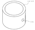
- FIG. 1 is a view showing an embodiment in which the present invention is applied to a deionization capacity type lightning rod, and a characteristic portion is shown in cross section.
- a lightning suppression lightning arrester A includes a lightning pole member 1 disposed at the top, a connecting member 2 provided at a lower portion of the lightning pole member 1, and the connecting member. And a support member 3 that is connected vertically through 2 to support the lightning pole member 1.
- the lightning pole member 1 includes an upper electrode body 11, a lower electrode body 12, and an insulator 13 provided between the upper electrode body 11 and the lower electrode body 12, and is formed in a substantially spherical shape as a whole. .
- the upper electrode body 11 and the lower electrode body 12 are formed in a slightly flat hemispherical shape in which a sphere is divided in half. Therefore, those surfaces are formed as curved surface portions 11a and 12a that come into contact with the atmosphere.
- the upper electrode body 11 and the lower electrode body 12 are formed in a cavity as illustrated. Further, a downward convex portion 11 b and an upward convex portion 12 b facing each other from the top surface of the upper electrode body 11 and the inner bottom surface of the lower electrode body 12 are formed.
- the interval H1 is set so that the downward convex portion 11b and the upward convex portion 12b exhibit a function as a discharging convex portion.
- the insulator 13 includes a cylindrical insulator 14 disposed between the upper electrode body 11 and the lower electrode body 12, and a cover member 15 disposed around the cylindrical insulator 14.
- the cylindrical insulator 14 is formed into a thick cylindrical shape by a fine ceramic formed by compacting and then firing 99.6% powder of alumina, and each end is connected to the upper electrode body 11. It fits in the annular grooves 11c and 12c formed in each of the opposing surfaces of the lower electrode body 12, and is integrated with an adhesive. Thus, the upper electrode body 11 and the lower electrode body 12 are connected in a liquid-tight and air-tight manner by the cylindrical insulator 14.
- peripheral wall of the cylindrical insulator 14 is provided with a vent hole 14a penetrating in the thickness direction of the peripheral wall in the peripheral wall portion of the intermediate portion in the length direction.
- the cover member 15 is made of fluororubber, and has an annular base portion 15a disposed so as to surround the outer periphery of the cylindrical insulator 14, and a continuous outer periphery of the base portion 15a. And a skirt portion 15 b that extends outward from both the electrode bodies 11 and 12 and covers a side portion of the lower electrode body 12.
- the cover member 15 When the pressure in the space S formed by the upper and lower electrode bodies 11 and 12 and the cylindrical insulator 14 rises, the cover member 15 allows the air in the space A to pass through. The compressed air is elastically deformed by acting through the hole 14a, and the compressed air is discharged to the outside through a gap with the cylindrical insulator 14.
- the upper electrode body 11, the lower electrode body 12, the connecting member 2, and the support member 3 are made of stainless steel having high conductivity.
- the support member 3 includes a support rod 31 located at the center and a support pipe 32 arranged coaxially on the outside thereof, and the support rod 31 is formed with a screw portion 31a.
- the support rod 31 has one end portion (upper end portion in the drawing) screwed to the lower electrode body 12 by the screw portion 31a and a nut 33 screwed to the screw portion 31a.
- the lower electrode body 12 and the support rod 31 are integrated by being pressed against the lower electrode body 12.
- a fixing nut 34 that presses the connecting member 2 against the lower surface of the lower electrode body 12 is screwed to the screw portion 31 a of the support rod 31.
- the lower end portion of the support rod 31 is positioned so as to protrude from the lower end of the support pipe 32 disposed so as to surround the support rod 31, and a mounting plate 35 is attached to the protruded portion. ing.
- the mounting plate 35 is pressed and fixed to the support pipe 32 by double nuts 36 and 36 that are screwed into a screw portion 31 a formed on the support rod 31.
- the lower electrode body 12 is electrically connected to the ground via the support member 3 and a grounding conductor (ground wire) (not shown).
- ground wire ground wire
- the maximum usable temperature of the fine ceramic constituting the cylindrical insulator 14 is as high as 1500 ° C., and the tensile strength is as large as 25 kg / mm 2 . As a result, the strength of the cylindrical insulator 14 connecting the two electrode bodies 11 and 12 is sufficiently secured.
- the cylindrical insulator 14 is made of a fine ceramic having no carbon group, no soot is generated when the temperature rises to a high temperature. Can do.
- the soundness of the lightning-suppressing type lightning arrester A also depends on the connection strength between the electrode bodies 11 and 12 and the cylindrical insulator 14.
- connection between the electrode bodies 11 and 12 and the cylindrical insulator 14 is performed by bonding with a heat-resistant inorganic adhesive, the bonding strength is sufficiently high even at high temperatures. It is ensured and the above-mentioned soundness is ensured.
- cover member 15 Furthermore, by forming the cover member 15 from fluoro rubber, environmental resistance such as aging resistance, weather resistance, ozone resistance, and flame resistance is ensured.
- the product number FC-2186 manufactured by Sumitomo 3M Co. was used as the fluororubber, and this fluororubber was held at a temperature of 300 ° C. for 1 hour and then returned to room temperature. There was no change in weight, no change in elasticity, and no discoloration or cracking.
Landscapes
- Elimination Of Static Electricity (AREA)
Abstract
The purpose of the invention is to ensure soundness of a lightning suppression type lightening protection device against lightning by ensuring mechanical strength and strength against thermal shock for a cylindrical insulator linking upper and lower electrode bodies ensuring the insulating performance thereof. The lightning protection device is provided with a lightning protection electrode member (1) having an insulator (13) that insulates an upper electrode body (11) and a lower electrode body (12), and a support member (3) provided on the lower part of the lightning protection electrode member. The insulator has a cylindrical insulator (14) disposed between the upper electrode body and the lower electrode body, and a cover member (15) disposed around the cylindrical insulator. The cylindrical insulator is formed from fine ceramics.
Description
本発明は、落雷を抑制することで、雷害から建築物や設備機器等の被保護体を保護するための落雷抑制型避雷装置に関するものである。
The present invention relates to a lightning-suppressing lightning arrester for protecting a protected object such as a building or equipment from lightning damage by suppressing lightning.
従来の雷保護概念では、落雷は防止できないものとの観点から、落雷を突針形避雷針(フランクリンロッド)に受けて大地に流す方式が大半であった。
In the conventional lightning protection concept, from the viewpoint that lightning strikes cannot be prevented, most of the methods receive lightning strikes to a ground with a pointed lightning rod (Franklin rod).
近年、雷保護の概念が改正され、角度法から回転球体法に移行する動き(新JIS A4201 2003年版)等もあるが、いずれにしても落雷による障害を完全に取り除くことは困難であった。特に、冬季雷のように雷撃規模(電流値や継続時間)が大きい場合、雷電流そのものや大地の電位上昇による各種の被害を起こしていた。
さらに、近年の機器はIC化のため異常電流に弱く、落雷による問題が大きくなる傾向となっている。 In recent years, the concept of lightning protection has been revised, and there is a movement (new JIS A4201 2003 edition) that shifts from the angle method to the rotating sphere method, but in any case, it has been difficult to completely eliminate the damage caused by lightning. In particular, when the scale of lightning strike (current value and duration) is large, such as lightning in winter, various damages are caused by the lightning current itself and the potential increase of the ground.
Furthermore, recent devices tend to be vulnerable to abnormal currents due to the integration of ICs, and the problem of lightning strikes is increasing.
一方、落雷を防止する技術として、電荷放散型防雷システム(DAS)が開発されている(特許文献1参照)。しかし、このシステムは大規模な装備となるため価格が高く、特殊な設備にしか用いられていないのが実情である。
近年、落雷を抑制する技術として、消イオン容量型避雷針(PDCE)が現れ効果を見せている(特許文献2、特許文献3参照)。 On the other hand, a charge dissipation type lightning protection system (DAS) has been developed as a technology for preventing lightning (see Patent Document 1). However, this system is expensive because it is a large-scale equipment, and it is actually used only for special equipment.
In recent years, a deionization capacity type lightning rod (PDCE) has appeared as a technique for suppressing a lightning strike and has been effective (seePatent Documents 2 and 3).
近年、落雷を抑制する技術として、消イオン容量型避雷針(PDCE)が現れ効果を見せている(特許文献2、特許文献3参照)。 On the other hand, a charge dissipation type lightning protection system (DAS) has been developed as a technology for preventing lightning (see Patent Document 1). However, this system is expensive because it is a large-scale equipment, and it is actually used only for special equipment.
In recent years, a deionization capacity type lightning rod (PDCE) has appeared as a technique for suppressing a lightning strike and has been effective (see
落雷は大気中で起こる放電現象であり、雷放電には雲内放電、雲間放電、雲―大地間放電等がある。雷放電で大きな被害を出すのは雲―大地間放電(以下落雷)である。落雷は雷雲(雲底)と大地または大地等に建設された構造物との間の電界強度が非常に大きくなり、その電荷が飽和状態となって大気の絶縁を破壊したときに発生する現象である。
Lightning strike is a discharge phenomenon that occurs in the atmosphere. Lightning discharge includes in-cloud discharge, cloud-to-cloud discharge, cloud-to-ground discharge, and the like. It is the cloud-to-ground discharge (hereinafter referred to as lightning strike) that causes significant damage from lightning discharge. A lightning strike is a phenomenon that occurs when the electric field strength between a thundercloud (cloud bottom) and a structure constructed on the earth or ground becomes very large, and its charge is saturated to break the insulation of the atmosphere. is there.
落雷の現象を詳細に観察すると、夏季に起こる一般的な落雷(夏季雷)の場合、雷雲が成熟すると雷雲からステップトリーダが大気の放電しやすいところを選びながら大地に近づいてくる。
ステップトリーダが大地とある程度の距離になると大地または建築物(避雷針)、木などからステップトリーダに向かって、微弱電流の上向きストリーマ(お迎え放電)が伸びてくる。
このストリーマとステップトリーダが結合すると、その経路を通って、雷雲と大地間に大電流(帰還電流)が流れる。これが落雷現象である。 When lightning phenomenon is observed in detail, in the case of a general lightning strike (summer lightning) that occurs in summer, when thunderclouds mature, steppeda approaches the ground while selecting a place where thunderclouds are likely to discharge air.
When the stepreader reaches a certain distance from the ground, a weak current upward streamer (greeting discharge) extends from the ground, a building (lightning rod), a tree, or the like toward the steppedre.
When this streamer and steppeda are coupled, a large current (feedback current) flows between the thundercloud and the ground through the path. This is a lightning phenomenon.
特許文献2に記載の消イオン容量型避雷針(PDCE)は落雷抑制タイプの避雷針であり、上向きストリーマの発生を起こりにくくしたものである。そのため、このPDCEを最高部に取り付けた施設には落雷現象が起き難い。
The deionization capacity type lightning rod (PDCE) described in Patent Document 2 is a lightning strike suppression type lightning rod, which is less likely to generate an upward streamer. For this reason, lightning strikes are unlikely to occur at facilities where the PDCE is installed at the highest part.
このPDCEは、絶縁体を挟んで配置される上部電極体及び下部電極体を有し、下部電極体のみが接地される。したがって、例えばマイナス電荷が雲底に分布した雷雲が近づくと、それとは逆の電荷(プラス電荷)が大地の表面に分布し、雲底のプラス電荷に引き寄せられて下部電極体にもプラス電荷が集まるようになる。すると、絶縁体を介して配置されている上部電極体は、コンデンサの作用でマイナス電荷を帯びる。この作用により、PDCEとその周辺における上向きストリーマの発生を起こりにくくし、落雷の発生を抑制する。
This PDCE has an upper electrode body and a lower electrode body arranged with an insulator interposed therebetween, and only the lower electrode body is grounded. Therefore, for example, when a thundercloud with negative charges distributed at the bottom of the cloud approaches, the opposite charge (plus charge) is distributed on the surface of the earth, attracted by the positive charge at the bottom of the cloud, and positive charges are also charged to the lower electrode body. Get together. Then, the upper electrode body arranged via the insulator is negatively charged by the action of the capacitor. This action makes it difficult to generate upward streamers in the PDCE and its surroundings, and suppresses the occurrence of lightning strikes.
北陸の平地でPDCEを設置し、5年にわたり雷観測カメラやLLS(Lightning Location System)を用いて落雷の有無を観測した結果、夏季には、PDCE設置箇所において落雷が観測されなかった。
これらの観測結果から、夏季雷に対して、PDCEは帰還電流を防止(落雷を防止)し、落雷による被害を抑制することが判った。 As a result of installing PDCE on the Hokuriku plain and using lightning observation cameras and LLS (Lightning Location System) for five years to observe the presence of lightning, no lightning was observed at the PDCE installation in the summer.
From these observation results, it was found that PDCE prevents return current (prevents lightning strike) and suppresses damage caused by lightning strikes during summer thunder.
本発明者らは、上記PDCEによる夏季雷の抑制のメカニズムを研究していく中で、PDCEの上下の電極体間の絶縁性を高めることにより、その抑制効果を増大させることができることを見出している。
The present inventors have found that the suppression effect can be increased by increasing the insulation between the upper and lower electrode bodies of the PDCE while studying the mechanism of summer thunder suppression by the PDCE. Yes.
ところで、PDCEへの落雷時には、上下の電極体間の空間部内圧力が、最大で80kg/cm2に達すると想定されており、PDCEの健全性を確保するために、前記両電極体を連結する絶縁体に対し、絶縁性能を確保しつつ十分な強度を確保することが要求されている。
By the way, when lightning strikes the PDCE, it is assumed that the pressure in the space between the upper and lower electrode bodies reaches a maximum of 80 kg / cm 2 , and the two electrode bodies are connected to ensure the soundness of the PDCE. It is required for an insulator to ensure sufficient strength while ensuring insulation performance.
また、PDCEへの落雷時には、急激な温度変化を伴うことから、耐熱衝撃性を高めることも要求されている。
Also, when lightning strikes the PDCE, it is accompanied by a rapid temperature change, so it is also required to increase the thermal shock resistance.
本発明の請求項1に記載の落雷抑制型避雷装置は、上部電極体と下部電極体とを絶縁する絶縁体を有する避雷極部材と、避雷極部材の下部に設けられた支持部材とを備え、前記絶縁体は、前記上部電極体と下部電極体との間に配置された筒状絶縁体と、筒状絶縁体の周囲に配置されたカバー部材とを有し、前記筒状絶縁体が、ファインセラミックによって形成されていることを特徴とする。
A lightning suppression type lightning arrester according to claim 1 of the present invention includes a lightning pole member having an insulator that insulates an upper electrode body and a lower electrode body, and a support member provided below the lightning pole member. The insulator includes a cylindrical insulator disposed between the upper electrode body and the lower electrode body, and a cover member disposed around the cylindrical insulator, and the cylindrical insulator is It is characterized by being formed of fine ceramic.
本発明によれば、前記筒状絶縁体をファインセラミックによって形成することにより、要求されている絶縁性能を十分に確保することができるばかりでなく、機械的強度ならびに耐熱衝撃性を確保して、落雷抑制型避雷装置の健全性を確保することができる。
According to the present invention, by forming the cylindrical insulator with fine ceramic, not only can the required insulation performance be sufficiently ensured, but also the mechanical strength and thermal shock resistance are ensured, The soundness of the lightning suppression type lightning arrester can be ensured.
本発明の請求項2に記載の落雷抑制型避雷装置は、請求項1に記載の前記筒状絶縁体が、前記上部電極体および下部電極体の対向面のそれぞれに形成された環状溝内に嵌合させられることにより、これらの上部電極体と下部電極体を連結するようになされているとともに、この筒状絶縁体の周壁には、周壁の厚さ方向に貫通する通気孔が設けられていることを特徴とする。
A lightning-suppressing lightning arrester according to claim 2 of the present invention is characterized in that the cylindrical insulator according to claim 1 is provided in an annular groove formed on each of opposing surfaces of the upper electrode body and the lower electrode body. The upper electrode body and the lower electrode body are connected by being fitted together, and the peripheral wall of the cylindrical insulator is provided with a vent hole penetrating in the thickness direction of the peripheral wall. It is characterized by being.
このような構成とすることにより、筒状絶縁体の周壁に、周壁の厚さ方向に貫通する通気孔を設けることで、万が一の落雷時において、避雷極部材の内部圧力上昇を一定の範囲に抑制することができる。
By adopting such a configuration, by providing a vent hole penetrating the peripheral wall of the cylindrical insulator in the thickness direction of the peripheral wall, in the unlikely event of a lightning strike, the internal pressure increase of the lightning pole member can be kept within a certain range. Can be suppressed.
本発明の請求項3に記載の落雷抑制型避雷装置は、請求項2に記載の前記筒状絶縁体と前記上部電極体および下部電極体とが、耐熱性無機系接着剤によって固着されていることを特徴とする。
A lightning-reducing lightning arrester according to claim 3 of the present invention is such that the tubular insulator according to claim 2 is fixed to the upper electrode body and the lower electrode body with a heat-resistant inorganic adhesive. It is characterized by that.
このような構成とすることにより、前記両電極体と筒状絶縁体との機械的な接続強度を高めることができるとともに、熱変化による接続強度の低下を抑制することができ、これによって、落雷による破損を防止することができる。
With such a configuration, the mechanical connection strength between the two electrode bodies and the cylindrical insulator can be increased, and a decrease in the connection strength due to a thermal change can be suppressed. Can prevent damage.
本発明によれば、上下電極体を連結する筒状絶縁体の絶縁性能を確保しつつ、機械的な強度ならびに熱衝撃への強度を確保して、落雷に対する落雷抑制型避雷装置の健全性を確保することができる。
According to the present invention, while ensuring the insulation performance of the cylindrical insulator connecting the upper and lower electrode bodies, the mechanical strength and the strength against thermal shock are ensured, and the soundness of the lightning suppression type lightning arrester against lightning strikes is improved. Can be secured.
以下、本発明の一実施形態について、図1~図3を参照して詳細に説明する。
図1は、本発明を消イオン容量型避雷針に適用した実施形態を示す図であり、特徴部分について断面で示している。 Hereinafter, an embodiment of the present invention will be described in detail with reference to FIGS.
FIG. 1 is a view showing an embodiment in which the present invention is applied to a deionization capacity type lightning rod, and a characteristic portion is shown in cross section.
この実施形態に係る落雷抑制型避雷装置Aは、図1に示すように、最上部に配置された避雷極部材1と、避雷極部材1の下部に設けられた連結部材2と、この連結部材2を介して鉛直に連結されて避雷極部材1を支持する支持部材3とを備えている。
As shown in FIG. 1, a lightning suppression lightning arrester A according to this embodiment includes a lightning pole member 1 disposed at the top, a connecting member 2 provided at a lower portion of the lightning pole member 1, and the connecting member. And a support member 3 that is connected vertically through 2 to support the lightning pole member 1.
避雷極部材1は、上部電極体11と、下部電極体12と、それら上部電極体11および下部電極体12間に設けられた絶縁体13とを備え、全体として概略球体状に形成されている。上部電極体11、下部電極体12は、球体が上下に半割りされた若干扁平な半球状に形成されている。したがって、それらの表面は大気と接触する曲面部11a、12aとして形成されている。
The lightning pole member 1 includes an upper electrode body 11, a lower electrode body 12, and an insulator 13 provided between the upper electrode body 11 and the lower electrode body 12, and is formed in a substantially spherical shape as a whole. . The upper electrode body 11 and the lower electrode body 12 are formed in a slightly flat hemispherical shape in which a sphere is divided in half. Therefore, those surfaces are formed as curved surface portions 11a and 12a that come into contact with the atmosphere.
上部電極体11及び下部電極体12は、図示のように空洞に形成されている。また、上部電極体11の天面及び下部電極体12の内底面から互いに向き合う下向き凸部11bおよび上向き凸部12bが形成されている。これら下向き凸部11bおよび上向き凸部12bは放電用凸部としての機能を発揮するように相互の間隔H1が設定されている。
The upper electrode body 11 and the lower electrode body 12 are formed in a cavity as illustrated. Further, a downward convex portion 11 b and an upward convex portion 12 b facing each other from the top surface of the upper electrode body 11 and the inner bottom surface of the lower electrode body 12 are formed. The interval H1 is set so that the downward convex portion 11b and the upward convex portion 12b exhibit a function as a discharging convex portion.
絶縁体13は、上部電極体11と下部電極体12との間に配置された筒状絶縁体14と、筒状絶縁体14の周囲に配置されたカバー部材15とを有している。
The insulator 13 includes a cylindrical insulator 14 disposed between the upper electrode body 11 and the lower electrode body 12, and a cover member 15 disposed around the cylindrical insulator 14.
前記筒状絶縁体14は、アルミナ99.6%の粉体を圧密成形した後に焼成して形成されたファインセラミックによって厚肉の円筒状に形成され、各端部が、前記上部電極体11と下部電極体12の対向面のそれぞれに形成されている環状溝11c、12cに嵌め込まれ、接着剤により一体化されている。
これによって、前記上部電極体11と下部電極体12が、前記筒状絶縁体14により液密及び気密に連結されている。 Thecylindrical insulator 14 is formed into a thick cylindrical shape by a fine ceramic formed by compacting and then firing 99.6% powder of alumina, and each end is connected to the upper electrode body 11. It fits in the annular grooves 11c and 12c formed in each of the opposing surfaces of the lower electrode body 12, and is integrated with an adhesive.
Thus, the upper electrode body 11 and thelower electrode body 12 are connected in a liquid-tight and air-tight manner by the cylindrical insulator 14.
これによって、前記上部電極体11と下部電極体12が、前記筒状絶縁体14により液密及び気密に連結されている。 The
Thus, the upper electrode body 11 and the
また、前記筒状絶縁体14の周壁には、その長さ方向の中間部の周壁部分に、周壁の厚さ方向に貫通する通気孔14aが設けられている。
Further, the peripheral wall of the cylindrical insulator 14 is provided with a vent hole 14a penetrating in the thickness direction of the peripheral wall in the peripheral wall portion of the intermediate portion in the length direction.
前記カバー部材15は、本実施形態においては、フッ素ゴムによって形成されており、前記筒状絶縁体14の外周を取り囲むようにして配設される環状の基部15aと、この基部15aの外周に連続して形成され、前記両電極体11・12の外方へ延設されるとともに、前記下部電極体12の側部を覆うスカート部15bとを備えている。
In this embodiment, the cover member 15 is made of fluororubber, and has an annular base portion 15a disposed so as to surround the outer periphery of the cylindrical insulator 14, and a continuous outer periphery of the base portion 15a. And a skirt portion 15 b that extends outward from both the electrode bodies 11 and 12 and covers a side portion of the lower electrode body 12.
そして、このカバー部材15は、前記上下の電極体11・12と前記筒状絶縁体14とで形成される空間部S内の圧力が上昇した際に、この空間部A内の空気が前記貫通孔14aを経て作用することにより弾性変形させられて、この圧縮空気を、前記筒状絶縁体14との隙間から外部へ放出するようになっている。
When the pressure in the space S formed by the upper and lower electrode bodies 11 and 12 and the cylindrical insulator 14 rises, the cover member 15 allows the air in the space A to pass through. The compressed air is elastically deformed by acting through the hole 14a, and the compressed air is discharged to the outside through a gap with the cylindrical insulator 14.
前記上部電極体11、前記下部電極体12、前記連結部材2、および、前記支持部材3は、高導電性を有するステンレスによって形成されている。
The upper electrode body 11, the lower electrode body 12, the connecting member 2, and the support member 3 are made of stainless steel having high conductivity.
前記支持部材3は、中心に位置する支持棒31と、その外側に同軸に配置された支持パイプ32とを備えており、前記支持棒31には螺子部31aが形成されている。
The support member 3 includes a support rod 31 located at the center and a support pipe 32 arranged coaxially on the outside thereof, and the support rod 31 is formed with a screw portion 31a.
そして、前記支持棒31は、その一端部(図においては上端部)が前記螺子部31aによって前記下部電極体12に螺着されているとともに、前記螺子部31aに螺合されているナット33が前記下部電極体12に圧接させられることによって、これらの下部電極体12および支持棒31が一体化されている。
The support rod 31 has one end portion (upper end portion in the drawing) screwed to the lower electrode body 12 by the screw portion 31a and a nut 33 screwed to the screw portion 31a. The lower electrode body 12 and the support rod 31 are integrated by being pressed against the lower electrode body 12.
また、前記支持棒31の螺子部31aには、前記連結部材2を前記下部電極体12の下面に押圧する固定ナット34が螺着されている。
Further, a fixing nut 34 that presses the connecting member 2 against the lower surface of the lower electrode body 12 is screwed to the screw portion 31 a of the support rod 31.
一方、前記支持棒31の下端部は、この支持棒31を取り囲んで配置されている前記支持パイプ32の下端から突出して位置させられており、この突出させられた部位に取り付けプレート35が装着されている。
On the other hand, the lower end portion of the support rod 31 is positioned so as to protrude from the lower end of the support pipe 32 disposed so as to surround the support rod 31, and a mounting plate 35 is attached to the protruded portion. ing.
この取り付けプレート35は、前記支持棒31に形成されている螺子部31aに螺合されるダブルナット36・36によって前記支持パイプ32に圧接されて固定されている。
The mounting plate 35 is pressed and fixed to the support pipe 32 by double nuts 36 and 36 that are screwed into a screw portion 31 a formed on the support rod 31.
前記下部電極体12は、支持部材3および図示しない接地用導電体(接地線)を介して大地に電気的に接続される。
これにより、この落雷抑制型避雷装置Aを鉛直に設置した状態において、雷雲等の影響により大地や構造物等が正電荷に帯電すると、上部電極体11の表面は負電荷に帯電し、大地や構造物等が負電荷に帯電すると、上部電極体の表面は正電荷に帯電するように設計されている。なお、この帯電機能自体は既存のPDCEと同様の原理に基づいている。 Thelower electrode body 12 is electrically connected to the ground via the support member 3 and a grounding conductor (ground wire) (not shown).
Thereby, in the state where this lightning suppression type lightning arrester A is installed vertically, when the ground or structure is charged with a positive charge due to the influence of thunderclouds or the like, the surface of the upper electrode body 11 is charged with a negative charge. When the structure or the like is charged with a negative charge, the surface of the upper electrode body is designed to be charged with a positive charge. This charging function itself is based on the same principle as that of the existing PDCE.
これにより、この落雷抑制型避雷装置Aを鉛直に設置した状態において、雷雲等の影響により大地や構造物等が正電荷に帯電すると、上部電極体11の表面は負電荷に帯電し、大地や構造物等が負電荷に帯電すると、上部電極体の表面は正電荷に帯電するように設計されている。なお、この帯電機能自体は既存のPDCEと同様の原理に基づいている。 The
Thereby, in the state where this lightning suppression type lightning arrester A is installed vertically, when the ground or structure is charged with a positive charge due to the influence of thunderclouds or the like, the surface of the upper electrode body 11 is charged with a negative charge. When the structure or the like is charged with a negative charge, the surface of the upper electrode body is designed to be charged with a positive charge. This charging function itself is based on the same principle as that of the existing PDCE.
本実施形態によれば、前記筒状絶縁体14を構成するファインセラミックの使用可能最高温度が1500℃と高く、また、引っ張り強さが25kg/mm2と大きいことから、前記避雷極部材1内の圧力が上昇し、前記両電極体11・12を連結する前記筒状絶縁体14の強度が十分に確保される。
According to this embodiment, the maximum usable temperature of the fine ceramic constituting the cylindrical insulator 14 is as high as 1500 ° C., and the tensile strength is as large as 25 kg / mm 2 . As a result, the strength of the cylindrical insulator 14 connecting the two electrode bodies 11 and 12 is sufficiently secured.
したがって、落雷による荷重の上昇や温度上昇に対して十分に耐えることができ、落雷抑制型避雷装置Aの健全性を確保することができる。
また、前記筒状絶縁体14が炭素基を持たないファインセラミックとしたことにより、高温に上昇した際においてすすの発生がなく、この結果、両電極体11・12間の絶縁低下を防止することができる。 Accordingly, it is possible to sufficiently withstand an increase in load or temperature due to a lightning strike, and to ensure the soundness of the lightning suppression type lightning arrester A.
Further, since thecylindrical insulator 14 is made of a fine ceramic having no carbon group, no soot is generated when the temperature rises to a high temperature. Can do.
また、前記筒状絶縁体14が炭素基を持たないファインセラミックとしたことにより、高温に上昇した際においてすすの発生がなく、この結果、両電極体11・12間の絶縁低下を防止することができる。 Accordingly, it is possible to sufficiently withstand an increase in load or temperature due to a lightning strike, and to ensure the soundness of the lightning suppression type lightning arrester A.
Further, since the
一方、前記落雷抑制型避雷装置Aの健全性は、前記両電極体11・12と前記筒状絶縁体14との接続強度にも依存している。
On the other hand, the soundness of the lightning-suppressing type lightning arrester A also depends on the connection strength between the electrode bodies 11 and 12 and the cylindrical insulator 14.
本実施形態においては、前記両電極体11・12と前記筒状絶縁体14との接続を、耐熱性の無機系接着剤による接着によって行なっていることから、その接着強度が高温下でも十分に確保され、前述した健全性が確保される。
In this embodiment, since the connection between the electrode bodies 11 and 12 and the cylindrical insulator 14 is performed by bonding with a heat-resistant inorganic adhesive, the bonding strength is sufficiently high even at high temperatures. It is ensured and the above-mentioned soundness is ensured.
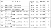
ここで、前述した接着強度にかかる試験結果を図3に示す。
この試験は、1/16.5の縮小モデルを用いて行なったもので、この結果から明らかなように、大きな熱衝撃が加わった場合にあっても接着強度が低下することはない。 Here, the test result concerning the adhesive strength mentioned above is shown in FIG.
This test was performed using a 1 / 16.5 scale model, and as is apparent from the results, even when a large thermal shock is applied, the adhesive strength does not decrease.
さらに、前記カバー部材15をフッ素ゴムによって形成したことにより、耐老化性、耐候性、耐オゾン性、耐炎性等の耐環境性が確保される。
Furthermore, by forming the cover member 15 from fluoro rubber, environmental resistance such as aging resistance, weather resistance, ozone resistance, and flame resistance is ensured.
確認のため、フッ素ゴムとして、住友スリーエム社製、製品番号FC-2186を用い、このフッ素ゴムを、温度300℃で1時間保持した後に常温へ戻す試験を、繰り返し5回行なった結果、各回ともに重量変化は見られず、かつ、弾力性に変化は見られず、かつ、変色やクラックの発生も見られなかった。
For confirmation, the product number FC-2186 manufactured by Sumitomo 3M Co. was used as the fluororubber, and this fluororubber was held at a temperature of 300 ° C. for 1 hour and then returned to room temperature. There was no change in weight, no change in elasticity, and no discoloration or cracking.
1 避雷極部材
2 連結部材
3 支持部材
11 上部電極体
11a 曲面部
11b 下向き凸部
11c 環状溝
12 下部電極体
12a 曲面部
12b 上向き凸部
12c 環状溝
13 絶縁体
14 筒状絶縁体
14a 通気孔
15 カバー部材
15a 基部
15b スカート部
31 支持棒
31a 螺子部
32 支持パイプ
33 ナット
34 固定ナット
35 取り付けプレート
36 ダブルナット
A 落雷抑制型避雷装置
S 空間部 DESCRIPTION OFSYMBOLS 1 Lightning pole member 2 Connection member 3 Support member 11 Upper electrode body 11a Curved part 11b Downward convex part 11c Annular groove 12 Lower electrode body 12a Curved part 12b Upward convex part 12c Annular groove 13 Insulator 14 Cylindrical insulator 14a Vent hole 15 Cover member 15a Base portion 15b Skirt portion 31 Support rod 31a Screw portion 32 Support pipe 33 Nut 34 Fixing nut 35 Mounting plate 36 Double nut A Lightning suppression lightning arrester S Space portion
2 連結部材
3 支持部材
11 上部電極体
11a 曲面部
11b 下向き凸部
11c 環状溝
12 下部電極体
12a 曲面部
12b 上向き凸部
12c 環状溝
13 絶縁体
14 筒状絶縁体
14a 通気孔
15 カバー部材
15a 基部
15b スカート部
31 支持棒
31a 螺子部
32 支持パイプ
33 ナット
34 固定ナット
35 取り付けプレート
36 ダブルナット
A 落雷抑制型避雷装置
S 空間部 DESCRIPTION OF
Claims (3)
- 上部電極体と下部電極体とを絶縁する絶縁体を有する避雷極部材と、避雷極部材の下部に設けられた支持部材と、を備え、
前記絶縁体は、前記上部電極体と下部電極体との間に配置された筒状絶縁体と、筒状絶縁体の周囲に配置されたカバー部材とを有し、
前記筒状絶縁体が、ファインセラミックによって形成されていることを特徴とする落雷抑制型避雷装置。 A lightning pole member having an insulator that insulates the upper electrode body and the lower electrode body, and a support member provided below the lightning pole member,
The insulator has a cylindrical insulator disposed between the upper electrode body and the lower electrode body, and a cover member disposed around the cylindrical insulator,
A lightning-reducing lightning arrester characterized in that the cylindrical insulator is made of fine ceramic. - 前記筒状絶縁体が、前記上部電極体および下部電極体の対向面のそれぞれに形成された環状溝内に嵌合させられることにより、これらの上部電極体と下部電極体を連結するようになされているとともに、この筒状絶縁体の周壁には、周壁の厚さ方向に貫通する通気孔が設けられていることを特徴とする、請求項1に記載の落雷抑制型避雷装置。 The cylindrical insulator is fitted into an annular groove formed in each of the opposing surfaces of the upper electrode body and the lower electrode body, thereby connecting the upper electrode body and the lower electrode body. The lightning-suppressing lightning arrester according to claim 1, wherein a vent hole penetrating in a thickness direction of the peripheral wall is provided in the peripheral wall of the cylindrical insulator.
- 前記筒状絶縁体と前記上部電極体および下部電極体とが、耐熱性無機系接着剤によって固着されていることを特徴とする請求項2に記載の落雷抑制型避雷装置。 3. The lightning-suppressing lightning arrester according to claim 2, wherein the cylindrical insulator, the upper electrode body, and the lower electrode body are fixed with a heat-resistant inorganic adhesive.
Applications Claiming Priority (2)
| Application Number | Priority Date | Filing Date | Title |
|---|---|---|---|
| JP2013-025766 | 2013-02-13 | ||
| JP2013025766A JP5757025B2 (en) | 2013-02-13 | 2013-02-13 | Lightning suppression type lightning arrester |
Publications (1)
| Publication Number | Publication Date |
|---|---|
| WO2014125699A1 true WO2014125699A1 (en) | 2014-08-21 |
Family
ID=51353718
Family Applications (1)
| Application Number | Title | Priority Date | Filing Date |
|---|---|---|---|
| PCT/JP2013/082229 WO2014125699A1 (en) | 2013-02-13 | 2013-11-29 | Lightning suppression type lightning protection device |
Country Status (2)
| Country | Link |
|---|---|
| JP (1) | JP5757025B2 (en) |
| WO (1) | WO2014125699A1 (en) |
Cited By (2)
| Publication number | Priority date | Publication date | Assignee | Title |
|---|---|---|---|---|
| CN106028612A (en) * | 2015-03-24 | 2016-10-12 | 丁特科国际公司 | Variable electric field balancing device |
| CN116151034A (en) * | 2023-04-17 | 2023-05-23 | 广东电网有限责任公司揭阳供电局 | Insulator core rod crisping prediction method, device, equipment and medium |
Citations (5)
| Publication number | Priority date | Publication date | Assignee | Title |
|---|---|---|---|---|
| JPH01140718U (en) * | 1988-03-18 | 1989-09-27 | ||
| JP2004039472A (en) * | 2002-07-04 | 2004-02-05 | Energy Support Corp | Switch |
| JP2010205687A (en) * | 2009-03-06 | 2010-09-16 | Sankosha Corp | Lightning arrester |
| JP2012182035A (en) * | 2011-03-02 | 2012-09-20 | Lightning Suppression Systems Co Ltd | Thunderbolt retardation arrester |
| JP2013196977A (en) * | 2012-03-21 | 2013-09-30 | Lightning Suppression Systems Co Ltd | Lightning suppression type lightning arrester |
-
2013
- 2013-02-13 JP JP2013025766A patent/JP5757025B2/en active Active
- 2013-11-29 WO PCT/JP2013/082229 patent/WO2014125699A1/en active Application Filing
Patent Citations (5)
| Publication number | Priority date | Publication date | Assignee | Title |
|---|---|---|---|---|
| JPH01140718U (en) * | 1988-03-18 | 1989-09-27 | ||
| JP2004039472A (en) * | 2002-07-04 | 2004-02-05 | Energy Support Corp | Switch |
| JP2010205687A (en) * | 2009-03-06 | 2010-09-16 | Sankosha Corp | Lightning arrester |
| JP2012182035A (en) * | 2011-03-02 | 2012-09-20 | Lightning Suppression Systems Co Ltd | Thunderbolt retardation arrester |
| JP2013196977A (en) * | 2012-03-21 | 2013-09-30 | Lightning Suppression Systems Co Ltd | Lightning suppression type lightning arrester |
Cited By (4)
| Publication number | Priority date | Publication date | Assignee | Title |
|---|---|---|---|---|
| CN106028612A (en) * | 2015-03-24 | 2016-10-12 | 丁特科国际公司 | Variable electric field balancing device |
| CN106028612B (en) * | 2015-03-24 | 2020-07-24 | 丁特科国际公司 | Variable electric field balancing device |
| CN116151034A (en) * | 2023-04-17 | 2023-05-23 | 广东电网有限责任公司揭阳供电局 | Insulator core rod crisping prediction method, device, equipment and medium |
| CN116151034B (en) * | 2023-04-17 | 2023-06-27 | 广东电网有限责任公司揭阳供电局 | Insulator core rod crisping prediction method, device, equipment and medium |
Also Published As
| Publication number | Publication date |
|---|---|
| JP2014154502A (en) | 2014-08-25 |
| JP5757025B2 (en) | 2015-07-29 |
Similar Documents
| Publication | Publication Date | Title |
|---|---|---|
| JP5780567B1 (en) | Lightning suppression type lightning arrester | |
| JP2010205687A (en) | Lightning arrester | |
| JP6885593B2 (en) | Lightning strike suppression type arrester and lightning arrester | |
| JP2008010241A (en) | Lightning arrester | |
| JP5839331B1 (en) | Lightning suppression type lightning arrester | |
| JP2012182035A (en) | Thunderbolt retardation arrester | |
| JP5780552B2 (en) | Lightning suppression type lightning arrester | |
| JP5757025B2 (en) | Lightning suppression type lightning arrester | |
| WO2018131660A1 (en) | Thunderbolt arrest-type lightning protection device | |
| JP6128540B1 (en) | Lightning suppression type lightning arrester | |
| JP6347340B1 (en) | Lightning suppression type lightning arrester and lightning arrester | |
| JP5839332B1 (en) | Lightning suppression type lightning arrester | |
| JP5780566B1 (en) | Lightning suppression type lightning arrester | |
| US10992111B2 (en) | Lightning strike suppression type lightning protection device and lightning arrestor | |
| JP6028293B1 (en) | Lightning suppression type lightning arrester | |
| US11594869B2 (en) | Lightning suppression type lightning discharger and arrester | |
| JP6128542B1 (en) | Lightning suppression type lightning arrester | |
| JP6934668B2 (en) | Lightning strike suppression type arrester and lightning strike suppression type lightning arrester | |
| JP5757491B1 (en) | Lightning suppression type lightning arrester | |
| JP6659046B2 (en) | Lightning strike suppression type lightning arrester | |
| JP2018078087A (en) | Thunderbolt retardation arrestor with protective function | |
| JP6356311B1 (en) | Lightning strike control device | |
| CN206432094U (en) | The full safety lightning arrester of one kind dropout | |
| JP2018195432A (en) | Lightning arrest type lightning protection device and lightning arrester | |
| JP5780554B2 (en) | Lightning suppression type lightning arrester |
Legal Events
| Date | Code | Title | Description |
|---|---|---|---|
| 121 | Ep: the epo has been informed by wipo that ep was designated in this application |
Ref document number: 13875234 Country of ref document: EP Kind code of ref document: A1 |
|
| NENP | Non-entry into the national phase |
Ref country code: DE |
|
| 32PN | Ep: public notification in the ep bulletin as address of the adressee cannot be established |
Free format text: NOTING OF LOSS OF RIGHTS PURSUANT TO RULE 112(1) EPC , EPO FORM 1205A DATED 19.01.16 |
|
| 122 | Ep: pct application non-entry in european phase |
Ref document number: 13875234 Country of ref document: EP Kind code of ref document: A1 |