WO2014123166A1 - トレランスリングおよびハードディスク装置 - Google Patents
トレランスリングおよびハードディスク装置 Download PDFInfo
- Publication number
- WO2014123166A1 WO2014123166A1 PCT/JP2014/052699 JP2014052699W WO2014123166A1 WO 2014123166 A1 WO2014123166 A1 WO 2014123166A1 JP 2014052699 W JP2014052699 W JP 2014052699W WO 2014123166 A1 WO2014123166 A1 WO 2014123166A1
- Authority
- WO
- WIPO (PCT)
- Prior art keywords
- tolerance ring
- circumferential direction
- hard disk
- base
- carriage
- Prior art date
- Legal status (The legal status is an assumption and is not a legal conclusion. Google has not performed a legal analysis and makes no representation as to the accuracy of the status listed.)
- Ceased
Links
Images






Classifications
-
- G—PHYSICS
- G11—INFORMATION STORAGE
- G11B—INFORMATION STORAGE BASED ON RELATIVE MOVEMENT BETWEEN RECORD CARRIER AND TRANSDUCER
- G11B5/00—Recording by magnetisation or demagnetisation of a record carrier; Reproducing by magnetic means; Record carriers therefor
- G11B5/48—Disposition or mounting of heads or head supports relative to record carriers ; arrangements of heads, e.g. for scanning the record carrier to increase the relative speed
- G11B5/54—Disposition or mounting of heads or head supports relative to record carriers ; arrangements of heads, e.g. for scanning the record carrier to increase the relative speed with provision for moving the head into or out of its operative position or across tracks
- G11B5/55—Track change, selection or acquisition by displacement of the head
- G11B5/5521—Track change, selection or acquisition by displacement of the head across disk tracks
- G11B5/5569—Track change, selection or acquisition by displacement of the head across disk tracks details of specially adapted mobile parts, e.g. electromechanical control devices
-
- F—MECHANICAL ENGINEERING; LIGHTING; HEATING; WEAPONS; BLASTING
- F16—ENGINEERING ELEMENTS AND UNITS; GENERAL MEASURES FOR PRODUCING AND MAINTAINING EFFECTIVE FUNCTIONING OF MACHINES OR INSTALLATIONS; THERMAL INSULATION IN GENERAL
- F16C—SHAFTS; FLEXIBLE SHAFTS; ELEMENTS OR CRANKSHAFT MECHANISMS; ROTARY BODIES OTHER THAN GEARING ELEMENTS; BEARINGS
- F16C19/00—Bearings with rolling contact, for exclusively rotary movement
- F16C19/02—Bearings with rolling contact, for exclusively rotary movement with bearing balls essentially of the same size in one or more circular rows
- F16C19/04—Bearings with rolling contact, for exclusively rotary movement with bearing balls essentially of the same size in one or more circular rows for radial load mainly
- F16C19/08—Bearings with rolling contact, for exclusively rotary movement with bearing balls essentially of the same size in one or more circular rows for radial load mainly with two or more rows of balls
-
- F—MECHANICAL ENGINEERING; LIGHTING; HEATING; WEAPONS; BLASTING
- F16—ENGINEERING ELEMENTS AND UNITS; GENERAL MEASURES FOR PRODUCING AND MAINTAINING EFFECTIVE FUNCTIONING OF MACHINES OR INSTALLATIONS; THERMAL INSULATION IN GENERAL
- F16C—SHAFTS; FLEXIBLE SHAFTS; ELEMENTS OR CRANKSHAFT MECHANISMS; ROTARY BODIES OTHER THAN GEARING ELEMENTS; BEARINGS
- F16C19/00—Bearings with rolling contact, for exclusively rotary movement
- F16C19/52—Bearings with rolling contact, for exclusively rotary movement with devices affected by abnormal or undesired conditions
- F16C19/527—Bearings with rolling contact, for exclusively rotary movement with devices affected by abnormal or undesired conditions related to vibration and noise
-
- F—MECHANICAL ENGINEERING; LIGHTING; HEATING; WEAPONS; BLASTING
- F16—ENGINEERING ELEMENTS AND UNITS; GENERAL MEASURES FOR PRODUCING AND MAINTAINING EFFECTIVE FUNCTIONING OF MACHINES OR INSTALLATIONS; THERMAL INSULATION IN GENERAL
- F16C—SHAFTS; FLEXIBLE SHAFTS; ELEMENTS OR CRANKSHAFT MECHANISMS; ROTARY BODIES OTHER THAN GEARING ELEMENTS; BEARINGS
- F16C27/00—Elastic or yielding bearings or bearing supports, for exclusively rotary movement
- F16C27/04—Ball or roller bearings, e.g. with resilient rolling bodies
-
- G—PHYSICS
- G11—INFORMATION STORAGE
- G11B—INFORMATION STORAGE BASED ON RELATIVE MOVEMENT BETWEEN RECORD CARRIER AND TRANSDUCER
- G11B5/00—Recording by magnetisation or demagnetisation of a record carrier; Reproducing by magnetic means; Record carriers therefor
- G11B5/48—Disposition or mounting of heads or head supports relative to record carriers ; arrangements of heads, e.g. for scanning the record carrier to increase the relative speed
- G11B5/4806—Disposition or mounting of heads or head supports relative to record carriers ; arrangements of heads, e.g. for scanning the record carrier to increase the relative speed specially adapted for disk drive assemblies, e.g. assembly prior to operation, hard or flexible disk drives
- G11B5/4813—Mounting or aligning of arm assemblies, e.g. actuator arm supported by bearings, multiple arm assemblies, arm stacks or multiple heads on single arm
-
- F—MECHANICAL ENGINEERING; LIGHTING; HEATING; WEAPONS; BLASTING
- F16—ENGINEERING ELEMENTS AND UNITS; GENERAL MEASURES FOR PRODUCING AND MAINTAINING EFFECTIVE FUNCTIONING OF MACHINES OR INSTALLATIONS; THERMAL INSULATION IN GENERAL
- F16C—SHAFTS; FLEXIBLE SHAFTS; ELEMENTS OR CRANKSHAFT MECHANISMS; ROTARY BODIES OTHER THAN GEARING ELEMENTS; BEARINGS
- F16C2370/00—Apparatus relating to physics, e.g. instruments
- F16C2370/12—Hard disk drives or the like
-
- F—MECHANICAL ENGINEERING; LIGHTING; HEATING; WEAPONS; BLASTING
- F16—ENGINEERING ELEMENTS AND UNITS; GENERAL MEASURES FOR PRODUCING AND MAINTAINING EFFECTIVE FUNCTIONING OF MACHINES OR INSTALLATIONS; THERMAL INSULATION IN GENERAL
- F16D—COUPLINGS FOR TRANSMITTING ROTATION; CLUTCHES; BRAKES
- F16D1/00—Couplings for rigidly connecting two coaxial shafts or other movable machine elements
- F16D1/06—Couplings for rigidly connecting two coaxial shafts or other movable machine elements for attachment of a member on a shaft or on a shaft-end
- F16D1/08—Couplings for rigidly connecting two coaxial shafts or other movable machine elements for attachment of a member on a shaft or on a shaft-end with clamping hub; with hub and longitudinal key
- F16D1/0829—Couplings for rigidly connecting two coaxial shafts or other movable machine elements for attachment of a member on a shaft or on a shaft-end with clamping hub; with hub and longitudinal key with radial loading of both hub and shaft by an intermediate ring or sleeve
- F16D1/0835—Couplings for rigidly connecting two coaxial shafts or other movable machine elements for attachment of a member on a shaft or on a shaft-end with clamping hub; with hub and longitudinal key with radial loading of both hub and shaft by an intermediate ring or sleeve due to the elasticity of the ring or sleeve
Definitions
- the present invention relates to a hard disk device and a tolerance ring used for the hard disk device and the like.
- hard disk devices are used in devices that perform information processing such as computers.
- this hard disk device has been mounted not only as an external storage device of a computer but also in home appliances such as a television and a video, and in electronic devices for automobiles.
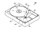
- FIG. 13 is a perspective view showing a schematic configuration of a conventional hard disk device.
- a conventional hard disk device 200 shown in FIG. 13 has a drive mechanism housed in a casing body 201.
- the drive mechanism supports a spindle 203 that rotates and drives a hard disk 202 that is a recording medium (this spindle is rotated by a motor (not shown)), and a magnetic head 204 that records information on and reads information from the hard disk 202.
- a carriage 205 that rotates on the surface of the hard disk 202, a VCM (Voice Coil Motor) 206 that controls the scanning of the magnetic head 204 by precisely rotating the carriage 205, a casing body 201, A pivot shaft 207 that couples the carriage 205 and a tolerance ring 208 that fixes the carriage 205 and the pivot shaft 207 are provided.
- the pivot shaft 207 has a substantially columnar shape, for example, and has a bearing configuration.
- FIG. 14 is a perspective view showing a configuration of a tolerance ring of a conventional hard disk device.
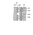
- FIG. 15 is a cross-sectional view showing the structure of the main part of a conventional hard disk device, and shows the structure in the vicinity of the carriage 205, the pivot shaft 207 and the tolerance ring 208.
- the conventional tolerance ring has a convex shape from a substantially rectangular region in the shape of a ring on the outer peripheral surface of a ring-shaped base portion 208a in which a belt-like member is substantially circulated along a predetermined direction.
- a plurality of convex portions 208b (contact portions) projecting from each other are provided.
- a tolerance ring having a plurality of convex contact portions protruding on the outer peripheral side is disclosed (for example, see Patent Documents 1 to 5).
- the contact portion presses against one side surface of the carriage or the pivot shaft to fix the carriage and the pivot shaft.
- the pivot shaft 207 has a bearing as described above to prevent the rotation of the carriage 205 from being transmitted to the casing body 201.
- the pivot shaft 207 includes a rod-shaped member 207a serving as the axis of the pivot shaft 207 and a bearing 207b provided on the outer periphery of the rod-shaped member 207a.
- the bearing 207 b is connected to the carriage 205 via the tolerance ring 208.
- the convex portion 208b of the tolerance ring 208 when the convex portion 208b of the tolerance ring 208 is disposed between the carriage 205 and the pivot shaft 207, the convex portion 208b fixes both the carriage 205 and the pivot shaft 207 in pressure contact with each other.
- the two convex portions 208b are arranged in the circumferential direction at the base portion 208a. It is preferable to be provided respectively on the base end side in the width direction orthogonal to.
- the bearing 207b prevents the central axis from tilting with respect to the central axis of the rod-shaped member 207a, so that the bearing balls forming a row along the outer periphery of the rod-shaped member 207a Are preferably provided at the edge portions of the arrangement area of the carriage 205 along the line.
- the bearing ball and the convex portion 208b of the bearing 207b are provided on the proximal end side of the coupling region of the carriage 205 of the pivot shaft 207 and the proximal end side of the base portion 208a of the tolerance ring 208, respectively.
- the bearing ball and the convex portion 208b are located at substantially the same height when assembled.
- the present invention has been made in view of the above, and provides a tolerance ring and a hard disk device capable of suppressing deterioration of the function of the bearing while maintaining the stability of fixation between the carriage and the pivot shaft.
- the purpose is to do.
- the tolerance ring according to the present invention has a plurality of convex portions protruding in the radial direction from the outer peripheral surface of the base portion in which the band-shaped member substantially circulates to form a ring shape,
- a tolerance ring provided along a circumferential direction of the base portion, wherein the base portion has a substantially cylindrical shape, a cylindrical portion provided with the convex portion, and the circumferential direction and the radial direction in the cylindrical portion;
- One or a plurality of curved portions provided in a part of the orthogonal width direction along the circumferential direction and curved in a convex shape with the main surface of the base portion facing the inner peripheral side of the cylindrical portion.
- the tolerance ring according to the present invention is characterized in that, in the above invention, the curved portions are respectively provided at both ends of the cylindrical portion in the width direction.
- the curved portion is provided between the plurality of convex portions.
- the bending portion is provided continuously along the circumferential direction.
- the tolerance ring according to the present invention is characterized in that, in the above invention, the radius of curvature of the end portion of the base portion in the circumferential direction is smaller than the radius of curvature of the portion other than the end portion in the circumferential direction.
- the tolerance ring according to the present invention is characterized in that, in the above invention, the radius of curvature continuously decreases in a direction from the portion other than the end portion toward the end portion.
- the tolerance ring according to the present invention is characterized in that, in the above invention, the tolerance ring has an edge portion in the width direction of the base portion, and has a notch portion notched in the width direction from at least one edge portion.
- the tolerance ring according to the present invention is characterized in that, in the above invention, one or a plurality of the notches are provided on the one edge.
- the hard disk device supports a hard disk as a recording medium, a magnetic head part for recording and reading information to and from the hard disk, and supports the magnetic head part, and rotates on the surface of the hard disk.
- Provided along the circumferential direction in a part of the circumferential direction and the width direction orthogonal to the radial direction in the cylindrical portion, and the main surface of the base portion is the cylindrical portion One or a plurality of curved portions convexly curved toward the inner peripheral side, and having a
- FIG. 1 is a perspective view showing a schematic configuration of a hard disk device according to an embodiment of the present invention.
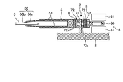
- FIG. 2 is a partial cross-sectional view showing a configuration of a main part of the hard disk device shown in FIG.
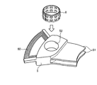
- FIG. 3 is a perspective view showing a configuration of a main part of the hard disk device shown in FIG.
- FIG. 4 is a perspective view showing a configuration of a tolerance ring used in the hard disk device according to the embodiment of the present invention.
- FIG. 5 is a cross-sectional view showing the configuration of the tolerance ring shown in FIG.
- FIG. 6 is a cross-sectional view showing a configuration of a main part of the hard disk device shown in FIG. FIG.
- FIG. 7 is a perspective view showing a configuration of a tolerance ring according to the first modification of the embodiment of the present invention.
- FIG. 8 is a cross-sectional view showing the configuration of the tolerance ring shown in FIG.
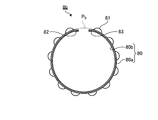
- FIG. 9 is a top view showing the configuration of the tolerance ring according to the second modification of the embodiment of the present invention.
- FIG. 10 is a perspective view showing a configuration of a tolerance ring according to the third modification of the embodiment of the present invention.
- FIG. 11 is a perspective view showing a configuration of a tolerance ring according to the fourth modification of the embodiment of the present invention.
- FIG. 12 is a perspective view showing a configuration of a tolerance ring according to the fifth modification of the embodiment of the present invention.
- FIG. 13 is a perspective view showing a schematic configuration of a conventional hard disk device.
- FIG. 14 is a perspective view showing a configuration of a tolerance ring of a conventional hard disk device.
- FIG. 15 is a cross-sectional view showing a configuration of a main part of a conventional hard disk device.
- FIG. 1 is a perspective view showing a schematic configuration of a hard disk device according to an embodiment of the present invention.
- the hard disk device 1 shown in FIG. 1 has a drive mechanism housed in a casing body 2.
- the drive mechanism supports a spindle 4 that rotationally drives a hard disk 3 that is a recording medium, a magnetic head unit 50 that records information on and reads information from the hard disk 3, and a carriage 5 that rotates on the surface of the hard disk 3;
- a VCM 6 that precisely rotates the carriage 5 to control scanning of the magnetic head unit 50, a columnar pivot shaft 7 that is fixed to the casing body 2 and connects the casing body 2 and the carriage 5, and the carriage 5 and pivot shaft And a tolerance ring 8 for fixing between the two.
- the pivot shaft 7 has a substantially columnar shape, for example, and has a bearing structure in which a bearing ball is disposed, for example.
- FIG. 2 is a partial cross-sectional view showing a configuration of a main part of the hard disk device 1 shown in FIG.
- FIG. 3 is a perspective view showing a configuration of a main part of the hard disk device 1 shown in FIG.
- the carriage 5 extends on the surface of the hard disk 3 and is connected to the arm 51 that holds the magnetic head unit 50 at the tip, the pivot shaft 7, and the coupling portion 52 that has a hollow space whose diameter is slightly larger than the diameter of the pivot shaft 7.
- the magnetic head unit 50 includes a suspension 50 a that floats with respect to the surface of the hard disk 3 by an air flow caused by the rotation of the hard disk 3, and an end of the suspension 50 a that is connected to the arm 51.
- a magnetic head 50b that is provided at an end portion on a different side and performs information recording and information reading.
- the carriage 5 has a plurality of magnetic head units 50 according to the number of hard disks 3.
- the VCM 6 includes a coil 60 connected to an end side different from the arm 51 side, and two magnets 61 sandwiching the coil 60.
- the VCM 6 drives the carriage 5 with a force generated by a current flowing through the coil 60 and a magnetic field.
- the carriage 5 rotates on the surface of the hard disk 3 with the central axis of the pivot shaft 7 as a rotation axis by the power from the VCM 6, and rotates the magnetic head unit 50 on the surface of the hard disk 3.
- the pivot shaft 7 has a bearing configuration as described above in order to prevent the rotation of the carriage 5 from being transmitted to the casing body 2.
- the pivot shaft 7 includes a rod-shaped member 71 that serves as an axis of the pivot shaft 7 and a bearing 72 provided on the outer periphery of the rod-shaped member 71.
- the bearing 72 two rows of bearing balls 72 a are arranged along the outer periphery of the rod-shaped member 71 along the central axis direction of the rod-shaped member 71.
- the bearing 72 is connected to the carriage 5 via a tolerance ring 8 described later, and the rod-like member 71 is connected to the casing body 2.
- the bearing ball 72 a rotates according to the rotational power of the carriage 5 by the VCM 6, so that the rotational power of the carriage 5 can be prevented from being transmitted to the rod-like member 71.
- Tolerance ring 8 is used for fixing between carriage 5 and pivot shaft 7.
- the tolerance ring 8 is inserted into the hollow space of the connecting portion 52 of the carriage 5, and the pivot shaft 7 is press-fitted (inserted) therein, thereby fixing between the carriage 5 and the pivot shaft 7.
- the carriage 5 is fixed so as to be rotatable around the central axis of the pivot shaft 7 (rod-like member 71).
- FIG. 4 is a perspective view showing the configuration of the tolerance ring 8.
- FIG. 5 is a cross-sectional view showing a configuration of the tolerance ring 8, and is a cross-sectional view having a plane parallel to the central axis of the tolerance ring 8 as a cut surface.
- the tolerance ring 8 is provided on the base 80, which is formed by a belt-shaped stainless steel that circulates in a substantially cylindrical shape, and is provided in the radial direction from the base 80 (direction perpendicular to the main surface of the base 80). And a plurality of convex portions 81 projecting from each other.
- the tolerance ring 8 may be formed using other metal materials besides stainless steel.
- the base 80 is provided at the center in the width direction (the direction orthogonal to the circumferential direction and the radial direction of the base 80), and is provided at each of the cylindrical portion 80a having a substantially cylindrical shape and both ends of the cylindrical portion 80a in the width direction. And a curved portion 80b having a principal surface curved.
- the curved portion 80b passes through the inner peripheral surface of the cylindrical portion 80a and is curved toward the substantially cylindrical curved surface N1 extending in the central axis direction of the cylindrical portion 80a. That is, the curved portion 80 b has an arc shape that is convex toward the inner peripheral side of the tolerance ring 8.
- the curved portion 80 b is continuously provided along the circumferential direction of the base portion 80.
- a substantially cylindrical shape that is an edge in the width direction of the curved portion 80b, and an edge on the outer peripheral side passes through the outer peripheral surface of the cylindrical portion 80a and extends in the central axis direction of the cylindrical portion 80a.
- the curved surface N2 On the curved surface N2.
- the convex portion 81 is provided along the circumferential direction of the cylindrical portion 80a and protrudes in the radial direction from the main surface on the outer peripheral side of the cylindrical portion 80a.
- each convex portion 81 is provided in two rows in the width direction of the tolerance ring 8. After the tolerance ring 8 is inserted into the opening on the carriage 5 side, the pivot shaft 7 is press-fitted into the tolerance ring 8. At this time, the convex portion 81 is pressed against the inner wall surface of the connecting portion 52 of the carriage 5, and the carriage 5 and the pivot shaft 7 are fixed.
- the length of the tolerance ring 8 in the circumferential direction is preferably equal to the circumferential length of the opening of the connecting portion 52.
- the plurality of convex portions 81 are described as being provided in two rows in the width direction, but may be one row or three or more rows.
- the number of the convex parts 81 to be arranged is, for example, a number that is a multiple of 3 in the circumferential direction.
- the multiple convex portions 81 By arranging the multiple convex portions 81 in multiples of 3, contact with the contact side surface is symmetrical with 120 °, the load applied to the side surface of the connecting portion 52 is made substantially uniform, and the operation efficiency of the bearing 72 is maintained with high accuracy. can do.
- the convex portion 81 has a symmetrical shape with respect to a plane that passes through the center of the convex portion 81 and is orthogonal to the main surface of the cylindrical portion 80a, so that the tolerance ring 8 can be moved up and down when the hard disk device 1 is assembled. Work efficiency can be improved because there is no need to worry.
- FIG. 6 is a cross-sectional view showing a configuration of a main part of the hard disk device 1 shown in FIG.
- the tolerance ring 8 when the tolerance ring 8 is disposed between the carriage 5 and the pivot shaft 7, the curved portion 80 b comes into contact with the pivot shaft 7 and deforms. Due to the deformation of the curved portion 80b, the edge in the width direction of the cylindrical portion 80a is lifted with respect to the pivot shaft 7 (bearing 72). Due to the change in the contact state of the cylindrical portion 80a (convex portion 81) with respect to the pivot shaft 7, the load distribution in the central axis direction of the tolerance ring 8 (cylindrical portion 80a) is increased in the curved portion 80b, and the load applied to the bearing ball 72a is increased. Since it can reduce, the increase in the rotational resistance of the bearing ball 72a which arises when the bearing 72 is compressed can be suppressed.
- the rigidity of the bending portion 80b is determined by the radial position of the edge portion of the bending portion 80b, the protruding amount of the bending portion 80b in the radial direction, the axial length of the bending portion 80b, and the like.
- the load applied to the bearing 72 by the bending portion 80b increases, and the load required when the bearing 72 (pivot shaft 7) is inserted into the tolerance ring 8 when the hard disk device 1 is assembled. (Hereinafter, insertion load) also increases.
- the bending portion 80b is not limited to the shape shown in FIG. 5, and the bending portion 80b is set so that the load applied to the bearing 72 by the bending portion 80b and the insertion load of the bearing 72 (pivot shaft 7) have a desired value.
- the radial position of the edge portion, the protruding amount of the curved portion 80b in the radial direction, the axial length of the curved portion 80b, and the like may be appropriately changed.
- the tolerance ring 8 includes the following method as an example of a manufacturing method.
- a progressive press is used in which a predetermined pressing process is sequentially performed on a base material extending in a strip shape.
- the base material extending in a flat plate shape is subjected to a contouring process by a press so that the contour (outer edge) of the tolerance ring 8 is formed, and a base material that forms the contour of the tolerance ring 8 is formed.
- the connected state of the base material and the base material is maintained by the runner.
- the formation process of the curved part 80b and the formation process of the convex part 81 are performed with respect to the shape
- the convex portions 81 are respectively formed at the positions described above by pressing.
- a bending process is performed on the base material on which the bending portion 80b and the convex portion 81 are formed.
- the base material is bent and shaped stepwise so that the convex portion 81 is on the outer surface side along the longitudinal direction of the main surface of the base material from both ends.
- the tolerance ring 8 can be obtained by cutting off the base material from the runner. Note that after the trimming process, the obtained tolerance ring 8 may be subjected to a process (setting process) for applying a stress greater than the maximum usable stress.
- the base 80 is provided at each of the cylindrical portion 80a in which the convex portion 81 is formed and both ends in the width direction of the cylindrical portion 80a. Since the curved portion 80b having an arc shape toward the periphery (the direction opposite to the protruding direction of the convex portion 81) is provided, the bearing is maintained while maintaining the stability of fixation between the carriage 5 and the pivot shaft 7. It is possible to suppress a decrease in function.
- the bending portion 80b is provided at both ends in the width direction of the base portion 80 (cylindrical portion 80a), so that the pivot shaft 7 is supported at both ends in the width direction of the base portion 80.
- the inclination of the central axis of the tolerance ring 8 with respect to the central axis of the pivot shaft 7 can be more reliably suppressed.
- a sleeve in which a belt-shaped member circulates between the rod-shaped member and the bearing ball forms a substantially cylindrical shape. It was provided.
- the tolerance ring 8 can easily press-fit the pivot shaft 7 into the tolerance ring 8, and can pivot the carriage 5 and the pivot 5 by pressing against the wall surface of the connecting portion 52 of the convex portion 81.
- the space between the shaft 7 can be securely fixed.
- FIG. 7 is a perspective view showing a configuration of a tolerance ring 8a according to the first modification of the present embodiment.
- FIG. 8 is a cross-sectional view showing the configuration of the tolerance ring 8a, and is a cross-sectional view with a plane perpendicular to the central axis of the tolerance ring 8a as a cut surface.
- the curved portions 80b are provided at both ends of the cylindrical portion 80a.
- the cylindrical portion 80c has a base portion 801 provided with a curved portion 80d at the center. There may be.
- the curved portion 80d shown in Modification 1 has a curved shape similar to that of the curved portion 80b described above, and is between the rows of convex portions 81 arranged in two rows in the width direction of the cylindrical portion 80c, that is, in the circumferential direction of the cylindrical portion 80c. And it is the center part of the width direction orthogonal to radial direction, Comprising: It is provided along the circumference direction. Even in the configuration of the first modification, the same effects as those of the above-described embodiment can be obtained.
- the cross-section of the curved portion having a cut surface that is a plane orthogonal to the main surfaces of the base portions 80 and 801 is uniformly arcuate (continuously along the circumferential direction). However, it may be a part that protrudes in a part of the region like the convex part 81. In this case, a plurality of bending portions are provided along the circumferential direction.
- the curved portion at this time is arranged according to the position of the convex portion 81, and is provided, for example, in a region overlapping with the convex portion 81 when viewed along the width direction of the cylindrical portion 80a.
- the curved portions may be provided in a region that does not overlap the convex portion 81 when viewed along the width direction of the cylindrical portion 80a. It may be provided so as to extend over the convex portion 81. Further, when a plurality of curved portions are provided in a convex shape, it is preferable that each curved portion is arranged so as to be symmetric with respect to the central axis of the tolerance ring.
- the bending portion is described as being provided between the rows of the convex portions 81.
- the curved portion may protrude in a convex shape between the convex portions 81, or may extend in a convex shape in the width direction perpendicular to the circumferential direction.
- FIG. 9 is a top view showing a configuration of a tolerance ring 8b according to the second modification of the present embodiment.
- the tolerance ring 8 b according to Modification 2 has different values of the radius of curvature of the end portions 82 and 83 in the circumferential direction and the radius of curvature of the portion other than the end portions 82 and 83 in the circumferential direction.
- the radius of curvature of the end portions 82 and 83 in the circumferential direction is equal to the radius of curvature of the connecting portion 52 of the carriage 5.
- the radius of curvature of the portion other than the end portions 82 and 83 in the circumferential direction is larger than the radius of curvature of the connecting portion 52 of the carriage 5.
- a broken line P 0 indicates a circular shape (a circumscribed circle shape) of a radius of curvature of a portion other than the end portions 82 and 83 in the circulation direction.
- the tolerance ring 8b is inserted into the connecting portion 52 of the carriage 5 and the open end portions 82 and 83 are closed, the shape along the circumferential direction is substantially equal to the curvature radius of the connecting portion 52.
- a circle with a radius can be formed.
- the tolerance ring 8 b is curved so that the radius of curvature continuously decreases in the direction from the portion other than the end portions 82 and 83 toward the end portions 82 and 83.
- the base material is bent so that the radius of curvature of the end portions 82 and 83 in the circumferential direction is smaller than the radius of curvature of the portion other than the end portions 82 and 83 in the circumferential direction.
- the base material is curved so that the radius of curvature decreases continuously (in a multistage manner) in a direction from the portion other than the end portions 82 and 83 toward the end portions 82 and 83.
- the radius of curvature of the end portions 82 and 83 in the circumferential direction is equal to the radius of curvature of the connecting portion 52 of the carriage 5, and the curvature radius of the portion other than the end portions 82 and 83 in the circumferential direction is the carriage 5. Therefore, the tolerance ring 8b is held inside the connecting portion 52 when inserted into the connecting portion 52 of the carriage 5, and the shape of the tolerance ring 8b in the circumferential direction is connected to the connecting portion 52. It can be a circle along the wall surface. For this reason, when inserting the tolerance ring 8b into the connecting portion 52 of the carriage 5, it can be inserted without damaging the wall surface of the connecting portion 52. Therefore, the occurrence of contamination due to insertion of the tolerance ring 8b can be suppressed.
- the conventional tolerance ring can be elastically deformed into a substantially circular shape whose shape along the circumferential direction is almost the same as the opening on the carriage side, but in reality, the tolerance ring is held in the carriage during the assembly work.
- the radius of curvature of the tolerance ring is designed to be larger than the radius of curvature of the carriage opening.
- the end side of the tolerance ring may be opened, and the radius of curvature of the end of the tolerance ring may be larger than the radius of curvature of the opening of the carriage.
- the insertion is performed without damaging the wall surface of the connecting portion 52 when inserted into the connecting portion 52. it can.
- the pivot shaft 7 when the pivot shaft 7 is press-fitted, the pivot shaft 7 can be press-fitted without damaging the inner peripheral surface of the tolerance ring 8b and / or the side surface of the pivot shaft 7. Therefore, the occurrence of contamination by the tolerance ring 8b can be further reliably suppressed.
- FIG. 10 is a perspective view schematically showing the configuration of the tolerance ring 8c according to the third modification of the present embodiment.
- the tolerance ring 8c according to the modified example 3 includes, in addition to the curved portion 80b and the convex portion 81 described above, two cutout portions 84a cut out in the width direction orthogonal to the circumferential direction (and the radial direction).
- the notch portion 84a includes an extending portion 841 extending in the width direction from the base end of the bending portion 80b (the edge in the width direction orthogonal to the circumferential direction and the radial direction of the base portion 80) to the cylindrical portion 80a, and the base end of the bending portion 80b.
- the cutout portion 84a includes the extending portion 841 extending in the width direction from the curved portion 80b to the cylindrical portion 80a, and at least the tip of the tip portion 842 is included in the formation region of the convex portion 81 in the circumferential direction of the cylindrical portion 80a. Preferably it is.
- the diameter of the tolerance ring becomes the diameter of the pivot shaft when the pivot shaft reaches the position where the convex portion is formed.
- the diameter is expanded along.
- the diameter of the ring formed by the base end on the pivot shaft insertion side is increased, and the diameter of the ring formed by the other base end is reduced by the reaction.
- the end on the opposite side to the insertion side rises. If the pivot shaft is further inserted from this state and the insertion is completed, the carriage shaft is rotated and inclined with respect to the central axis of the pivot shaft, which affects the assembly accuracy of the drive mechanism. .
- the notch 84a that is notched in the direction orthogonal to the circumferential direction (and the radial direction) of the base 80 of the tolerance ring 8c is provided.
- FIG. 11 is a perspective view schematically showing a configuration of a tolerance ring 8d according to the fourth modification of the present embodiment.
- the R-shaped diameter of the distal end portion 842 has been described as being equivalent to the length of the extending portion 841 in the circumferential direction.
- the tolerance ring 8d illustrated in FIG. It may be a notch 84b having a tip 843 having a diameter larger than the length of the base 80 in the circumferential direction at 841.
- FIG. 12 is a perspective view schematically showing a configuration of a tolerance ring 8e according to the fifth modification of the embodiment of the present invention.
- the notches 84a and 84b are described as being provided at both ends in the width direction of the tolerance ring.
- One or a plurality of (two in the fifth modification) may be provided on the side.
- the base end where the notch 84a is provided is the base end on the side different from the insertion side of the pivot shaft 7 of the tolerance ring 8e.
- the notch portion 84a is provided on one end side like the tolerance ring 8e according to the modified example 5
- the notch portion 84a is provided on the base end on the side different from the insertion side of the pivot shaft 7 of the tolerance ring 8e.
- the rotation suppression effect of 5 can be further increased.
- the notch portion 84a having a length of 1.0 mm is formed in the width direction (direction orthogonal to the circumferential direction), compared to the case where the notch portions 84a each having a length of 0.5 mm are formed at both ends, The effect of suppressing the rotation of the carriage 5 can be further increased when a 1.0 mm cutout is formed at one end (the base end on the side different from the insertion side of the pivot shaft 7).
- one or a plurality of cutout portions according to the modified examples 3 to 5 are provided at positions that equally divide the sides in the longitudinal direction. Further, when a plurality of notches are provided, the length of the extending portion 841 (the length in the direction orthogonal to the longitudinal direction of the tolerance ring) may be the same or different from each other. .
- the tolerance ring and the hard disk device according to the present invention are useful for suppressing deterioration of the function of the bearing while maintaining the stability of fixation between the carriage and the pivot shaft.
Landscapes
- Engineering & Computer Science (AREA)
- General Engineering & Computer Science (AREA)
- Mechanical Engineering (AREA)
- Moving Of Heads (AREA)
- Mounting Of Bearings Or Others (AREA)
Abstract
本発明にかかるトレランスリングは、帯状の部材が略周回してリング状をなす基部(80)の外周面から径方向に突出する複数の凸部(81)が、基部(80)の周回方向に沿って設けられたトレランスリング(8)であって、基部(80)は、略円筒状をなし、凸部(81)が設けられた円筒部(80a)と、円筒部(80a)における周回方向および径方向と直交する幅方向の一部に周回方向に沿って設けられ、基部(80)の主面を円筒部(80a)の内周側に向けて凸状に湾曲した湾曲部(80b)と、を有する。
Description
本発明は、ハードディスク装置、およびこのハードディスク装置等に用いられるトレランスリングに関するものである。
従来、コンピュータ等の情報処理を行う機器において、ハードディスク装置が使用されている。このハードディスク装置は、近年にいたっては、コンピュータの外部記憶装置としてばかりではなく、テレビやビデオ等の家電製品、自動車用の電子機器類に搭載されるようになってきている。
図13は、従来のハードディスク装置の概略構成を示す斜視図である。図13に示す従来のハードディスク装置200は、ケーシング本体201内に駆動機構が収納されている。駆動機構は、記録メディアであるハードディスク202を回転駆動するスピンドル203(このスピンドルは不図示のモータにて回転される)と、ハードディスク202への情報記録および情報読み出しを行う磁気ヘッド204を支持し、ハードディスク202の表面上を回動するキャリッジ205と、キャリッジ205を精密に回動させて磁気ヘッド204の走査を制御するVCM(Voice Coil Motor)206と、ケーシング本体201に固定され、ケーシング本体201とキャリッジ205とを連結するピボット軸207と、キャリッジ205とピボット軸207との間を固定するトレランスリング208と、を有する。なお、ピボット軸207は、例えば略柱状をなし、ベアリングの構成を有する。
図14は、従来のハードディスク装置のトレランスリングの構成を示す斜視図である。図15は、従来のハードディスク装置の要部の構成を示す断面図であって、キャリッジ205、ピボット軸207およびトレランスリング208近傍の構成を示す図である。従来のトレランスリングは、図14に示すトレランスリング208のように、帯状の部材を所定方向に沿って略周回させたリング状をなす基部208aの外周面において、帯状の略矩形の領域から凸状に突出している複数の凸部208b(接触部)が設けられている。このトレランスリング208をキャリッジ205側の開口に挿入した後、トレランスリング208の内部にピボット軸207が圧入される(図15参照)。
このようなトレランスリングとして、外周側に突出した凸状の接触部を複数有するトレランスリングが開示されている(例えば、特許文献1~5を参照)。特許文献1~5に示すトレランスリングでは、接触部がキャリッジまたはピボット軸のどちらか一方の側面に圧接して、キャリッジとピボット軸との間を固定する。
ピボット軸207は、キャリッジ205の回転動作がケーシング本体201に伝達しないようにするため、上述したようにベアリングを有している。例えば、図15に示すように、ピボット軸207は、ピボット軸207の軸となる棒状部材207aと、棒状部材207aの外周に設けられるベアリング207bとを有する。このとき、ベアリング207bはトレランスリング208を介してキャリッジ205と連結している。この構成により、キャリッジ205の回転動力に応じてベアリング207bのベアリングボールが回転することによって、キャリッジ205の回転動力が棒状部材207aに伝達することを防止する。
ところで、トレランスリング208の凸部208bは、キャリッジ205とピボット軸207との間に配設された際、キャリッジ205およびピボット軸207に圧接した状態で両者を固定する。このとき、キャリッジ205の開口の中心軸に対して、ピボット軸207の中心軸(棒状部材207aの中心軸)が傾斜することを防止するため、二つの凸部208bは、基部208aにおいて、周回方向と直交する幅方向の基端側にそれぞれ設けられることが好ましい。
一方、ベアリング207bは、棒状部材207aの中心軸に対して中心軸が傾斜することを防止するため、棒状部材207aに対し、棒状部材207aの外周に沿って列をなすベアリングボールが、中心軸方向に沿ったキャリッジ205の配設領域の縁端部にそれぞれ設けられることが好ましい。
しかしながら、ベアリング207bのベアリングボールおよび凸部208bが、ピボット軸207のキャリッジ205の連結領域の基端側、およびトレランスリング208の基部208aの基端側にそれぞれ設けられた場合、ピボット軸207の中心軸方向に沿ってみたときに、ベアリングボールおよび凸部208bが、組み付け時にほぼ同じ高さに位置することとなる。
このとき、凸部208bがキャリッジ205からの荷重をピボット軸207に加える際の最大付加方向(図15の矢印方向)にベアリングボールが存在する。これにより、凸部208bがベアリング207bに荷重を加えた際、ベアリング207bが圧迫され、ベアリングボールの回転抵抗が増加して、結果的にベアリング207bの機能を十分に発揮できなくなる場合があった。
本発明は、上記に鑑みてなされたものであって、キャリッジとピボット軸との間の固定の安定性を維持しつつ、ベアリングの機能低下を抑制することが可能なトレランスリングおよびハードディスク装置を提供することを目的とする。
上述した課題を解決し、目的を達成するために、本発明にかかるトレランスリングは、帯状の部材が略周回してリング状をなす基部の外周面から径方向に突出する複数の凸部が、前記基部の周回方向に沿って設けられたトレランスリングであって、前記基部は、略円筒状をなし、前記凸部が設けられた円筒部と、前記円筒部における前記周回方向および前記径方向と直交する幅方向の一部に前記周回方向に沿って設けられ、前記基部の主面を円筒部の内周側に向けて凸状に湾曲した1または複数の湾曲部と、を有することを特徴とする。
また、本発明にかかるトレランスリングは、上記の発明において、前記湾曲部は、前記円筒部の前記幅方向の両端にそれぞれ設けられることを特徴とする。
また、本発明にかかるトレランスリングは、上記の発明において、前記湾曲部は、前記複数の凸部の間に設けられることを特徴とする。
また、本発明にかかるトレランスリングは、上記の発明において、前記湾曲部は、前記周回方向に沿って連続的に設けられることを特徴とする。
また、本発明にかかるトレランスリングは、上記の発明において、前記基部の前記周回方向における端部の曲率半径が、前記周回方向における前記端部以外の部分の曲率半径より小さいことを特徴とする。
また、本発明にかかるトレランスリングは、上記の発明において、前記端部以外の部分から前記端部に向かう方向に従って連続的に曲率半径が小さくなることを特徴とする。
また、本発明にかかるトレランスリングは、上記の発明において、前記基部の前記幅方向の縁部であって、少なくとも一方の縁部から、前記幅方向に切り欠かれた切欠部を有することを特徴とする。
また、本発明にかかるトレランスリングは、上記の発明において、前記切欠部は、前記一方の縁部に、1または複数設けられることを特徴とする。
また、本発明にかかるハードディスク装置は、記録メディアであるハードディスクと、前記ハードディスクへの情報記録および情報読み出しを行う磁気ヘッド部と、前記磁気ヘッド部を支持し、前記ハードディスクの面上を回動するキャリッジと、帯状の部材が略周回してリング状をなす基部の外周面から径方向に突出する複数の凸部が、前記基部の周回方向に沿って設けられ、前記キャリッジに形成された中空空間に収容されるトレランスリングと、前記トレランスリングの前記リング状の内部に挿入されるピボット軸と、を備え、前記基部は、略円筒状をなし、前記凸部が設けられた円筒部と、前記円筒部における前記周回方向および前記径方向と直交する幅方向の一部に前記周回方向に沿って設けられ、前記基部の主面を前記円筒部の内周側に向けて凸状に湾曲した1または複数の湾曲部と、を有することを特徴とする。
本発明によれば、キャリッジとピボット軸との間の固定の安定性を維持しつつ、ベアリングの機能低下を抑制することができるという効果を奏する。
以下、本発明を実施するための形態を図面とともに詳細に説明する。なお、以下の実施の形態により本発明が限定されるものではない。また、以下の説明において参照する各図は、本発明の内容を理解でき得る程度に形状、大きさ、および位置関係を概略的に示してあるに過ぎない。すなわち、本発明は各図で例示された形状、大きさ、および位置関係のみに限定されるものではない。なお、以下の説明では、トレランスリングを用いる装置の一例としてハードディスク装置を説明する。
図1は、本発明の実施の形態にかかるハードディスク装置の概略構成を示す斜視図である。図1に示すハードディスク装置1は、ケーシング本体2内に駆動機構が収納されている。駆動機構は、記録メディアであるハードディスク3を回転駆動するスピンドル4と、ハードディスク3への情報記録および情報読み出しを行う磁気ヘッド部50を支持し、ハードディスク3の面上を回動するキャリッジ5と、キャリッジ5を精密に回動させて磁気ヘッド部50の走査を制御するVCM6と、ケーシング本体2に固定され、ケーシング本体2とキャリッジ5とを連結する柱状のピボット軸7と、キャリッジ5とピボット軸7との間を固定するトレランスリング8と、を有する。なお、ピボット軸7は、例えば略柱状をなし、例えば内部にベアリングボールが配設されてなるベアリング構造をなす。
図2は、図1に示すハードディスク装置1の要部の構成を示す部分断面図である。図3は、図1に示すハードディスク装置1の要部の構成を示す斜視図である。キャリッジ5は、ハードディスク3の面上に延び、先端で磁気ヘッド部50を保持するアーム51と、ピボット軸7と連結し、ピボット軸7の径より若干大きい径の中空空間を有する連結部52と、を有する。磁気ヘッド部50は、図2に示すように、ハードディスク3の回転による空気流によって、ハードディスク3の面に対して浮上するサスペンション50aと、サスペンション50aの端部であって、アーム51に連なる側と異なる側の端部に設けられ、情報記録および情報読み出しを行う磁気ヘッド50bと、を有する。なお、ハードディスク装置1がハードディスク3を複数有する場合、キャリッジ5は、ハードディスク3の数に応じて複数の磁気ヘッド部50を有する。
VCM6は、アーム51側と異なる端部側に連結されるコイル60と、コイル60を挟み込む2つの磁石61とを有する。VCM6は、コイル60に流れる電流と磁場とによって発生する力でキャリッジ5を駆動する。これにより、キャリッジ5は、VCM6からの動力によってピボット軸7の中心軸を回転の軸としてハードディスク3の面上を回動し、磁気ヘッド部50をハードディスク3の面上で回動させる。
ピボット軸7は、キャリッジ5の回転動作がケーシング本体2に伝達しないようにするため、上述したようにベアリングの構成を有している。例えば、図2に示すように、ピボット軸7は、ピボット軸7の軸となる棒状部材71と、棒状部材71の外周に設けられるベアリング72とを有する。ベアリング72は、棒状部材71の外周に沿って列をなすベアリングボール72aが、棒状部材71の中心軸方向に沿って二列配設されている。ベアリング72は後述するトレランスリング8を介してキャリッジ5と連結し、棒状部材71はケーシング本体2と連結している。この場合、VCM6によるキャリッジ5の回転動力に応じてベアリングボール72aが回転することによって、キャリッジ5の回転動力が棒状部材71に伝達することを防止することができる。
キャリッジ5とピボット軸7との間の固定には、トレランスリング8が用いられている。トレランスリング8は、キャリッジ5の連結部52の中空空間に挿入され、内部にピボット軸7が圧入(挿入)されることによって、キャリッジ5とピボット軸7との間を固定する。これにより、キャリッジ5は、ピボット軸7(棒状部材71)の中心軸まわりに回動自在に固定される。
図4は、トレランスリング8の構成を示す斜視図である。図5は、トレランスリング8の構成を示す断面図であって、トレランスリング8の中心軸と平行な平面を切断面とする断面図である。トレランスリング8は、図4に示すように、帯状のステンレスが周回して略筒状をなす基部80と、基部80に設けられ、基部80から径方向(基部80の主面と直交する方向)に突出する複数の凸部81と、を有する。なお、トレランスリング8は、ステンレスのほか、他の金属材料を用いて形成されるものであってもよい。
基部80は、幅方向(基部80の周回方向および径方向と直交する方向)の中央部に設けられ、略円筒状をなす円筒部80aと、円筒部80aにおける幅方向の両端部にそれぞれ設けられ、主面が湾曲されてなる湾曲部80bと、を有する。
湾曲部80bは、図5に示すように、円筒部80aの内周面を通過し、円筒部80aの中心軸方向に延びる略筒状の曲面N1側に湾曲している。すなわち、湾曲部80bは、トレランスリング8の内周側に凸となる弧状をなしている。湾曲部80bは、基部80の周回方向に沿って連続的に設けられている。また、本実施の形態では、湾曲部80bの幅方向の縁端であって、外周側の縁端が、円筒部80aの外周面を通過し、円筒部80aの中心軸方向に延びる略筒状の曲面N2上にある。
凸部81は、円筒部80aの周回方向に沿って設けられ、円筒部80aの外周側の主面から径方向に突出する。
また、各凸部81は、トレランスリング8の幅方向に二列設けられる。トレランスリング8は、キャリッジ5側の開口に挿入された後、トレランスリング8の内部にピボット軸7が圧入される。このとき、キャリッジ5の連結部52の内部壁面に凸部81が圧接し、キャリッジ5とピボット軸7との間を固定する。なお、トレランスリング8の周回方向の長さは、連結部52の開口の周の長さと等しいことが好ましい。
また、本実施の形態では、複数の凸部81が幅方向に二列設けられるものとして説明するが、一列であってもよいし、三列以上であってもよい。
また、配置される凸部81の数は、例えば周回方向に3の倍数となる個数配置される。凸部81を3の倍数個配置することで、当接側面に対して120°対称で接触して、連結部52の側面に加わる荷重を略均一にし、ベアリング72の動作効率を高精度に維持することができる。また、凸部81において、凸部81の中心を通過し、かつ円筒部80aの主面と直交する平面に対して対称な形状とすることにより、ハードディスク装置1の組み付け時にトレランスリング8の上下を気にする必要がなくなるため、作業効率を向上させることができる。
図6は、図1に示すハードディスク装置1の要部の構成を示す断面図である。図6に示すように、トレランスリング8がキャリッジ5とピボット軸7との間に配設されると、湾曲部80bがピボット軸7に接触して変形する。この湾曲部80bの変形により、円筒部80aの幅方向の縁端がピボット軸7(ベアリング72)に対して浮き上がる。この円筒部80a(凸部81)のピボット軸7に対する接触状態の変化により、トレランスリング8(円筒部80a)の中心軸方向の荷重分布が湾曲部80bにおいて高くなり、ベアリングボール72aに加わる荷重を低減することができるため、ベアリング72が圧迫されることにより生じるベアリングボール72aの回転抵抗の増加を抑制することができる。
湾曲部80bの剛性は、湾曲部80bの縁端部の径方向の位置、湾曲部80bの径方向の突出量、湾曲部80bの軸方向の長さなどにより決定される。湾曲部80bの剛性を高くすると、湾曲部80bがベアリング72に与える荷重が大きくなり、ハードディスク装置1の組み付け時、ベアリング72(ピボット軸7)をトレランスリング8内部に挿入する際に必要となる荷重(以下、挿入荷重)も高くなる。また、湾曲部80bの剛性を低くすると、ベアリング72(ピボット軸7)の挿入荷重は小さくなり、湾曲部80bがベアリング72(ピボット軸7)に与える荷重も小さくなる。ここで、挿入荷重が大きくなり過ぎると、ベアリング72(ピボット軸7)をトレランスリング8の内部に挿入できなくなったり、トレランスリング8などを損傷させたりするおそれがある。したがって、湾曲部80bは、図5で示した形状に限定されず、湾曲部80bがベアリング72に与える荷重やベアリング72(ピボット軸7)の挿入荷重が所望の値となるように、湾曲部80bの縁端部の径方向の位置、湾曲部80bの径方向の突出量、湾曲部80bの軸方向の長さなどを適宜変更してもよい。
ここで、トレランスリング8は、作製方法の一例として以下の方法が挙げられる。この作製方法では、帯状に延びる母材に対して順次所定のプレス工程を施す順送プレスを用いる。まず、平板状に延びる母材に対してプレスにより外形取り処理を行って、トレランスリング8の外形(外縁)が形取られ、トレランスリング8の外形をなす基材を成形する。なお、このとき、基材が母材から離脱することを防止するため、ランナーによって基材と母材との連結状態が維持されている。次に、成形された基材に対して、湾曲部80bの形成処理および凸部81の成形処理を行う。凸部81は、プレスによって上述した位置にそれぞれ成形される。
続いて、湾曲部80bおよび凸部81が成形された基材に対して湾曲処理を行う。この湾曲工程では、両端側から基材の主面の長手方向に沿って凸部81が外表面側となるように段階的に基材を湾曲させて成形する。
湾曲工程が終了後、得られた基材に対してトリミング処理を行う。トリミング処理では、ランナーから基材を切り落とすことによって、トレランスリング8を得ることができる。なお、トリミング処理後、得られたトレランスリング8に対して、最大使用応力以上の応力を負荷する処理(セッチング処理)を行ってもよい。
上述した本実施の形態によれば、トレランスリング8において、基部80が、凸部81が形成された円筒部80aと、円筒部80aの幅方向の両端部にそれぞれ設けられ、トレランスリング8の内周(凸部81の突出方向と反対方向)に向けて弧状をなす湾曲部80bと、を有するようにしたので、キャリッジ5とピボット軸7との間の固定の安定性を維持しつつ、ベアリングの機能低下を抑制することができる。
また、上述した本実施の形態によれば、湾曲部80bを基部80(円筒部80a)の幅方向の両端部に設けるようにしたので、基部80の幅方向の両端側でピボット軸7を支持することとなり、ピボット軸7の中心軸に対してトレランスリング8の中心軸が傾斜することを一層確実に抑制することができる。
また、従来のハードディスク装置では、例えば棒状部材およびベアリングボールの間の接触部分の圧迫を低減するため、棒状部材とベアリングボールとの間に、帯状の部材が周回して略筒状をなすスリーブを設けていた。これに対し、上述した本実施の形態によれば、上述したスリーブを設けることなく、棒状部材71およびベアリングボール72aの間の接触部分の圧迫を低減することができる。このため、ハードディスク装置1の部品点数を増大することなく、棒状部材71およびベアリングボール72aの間の接触部分の圧迫を低減することができるという効果を奏する。
上述したように、本実施の形態にかかるトレランスリング8は、ピボット軸7をトレランスリング8内部に容易に圧入することができるとともに、凸部81の連結部52の壁面に対する圧接によってキャリッジ5とピボット軸7との間を確実に固定することができる。
図7は、本実施の形態の変形例1にかかるトレランスリング8aの構成を示す斜視図である。図8は、トレランスリング8aの構成を示す断面図であって、トレランスリング8aの中心軸と直交する平面を切断面とする断面図である。上述した実施の形態では、円筒部80aの両端に湾曲部80bを設けるものとして説明したが、変形例1のように、円筒部80cの中央部に湾曲部80dを設けた基部801を有するものであってもよい。変形例1に示す湾曲部80dは、上述した湾曲部80bと同様の湾曲形状をなし、円筒部80cの幅方向に二列配置されている凸部81の列間、すなわち円筒部80cにおける周回方向および径方向と直交する幅方向の中央部であって、周回方向に沿って設けられている。この変形例1の構成においても、上述した実施の形態と同様の効果を得ることができる。
なお、変形例1の構成に対して、上述した実施の形態にかかる湾曲部80bを設けてもよい。また、上述した実施の形態および変形例1では、湾曲部が、基部80,801の主面に直交する平面を切断面とする断面が、一様に弧状をなす(周回方向に沿って連続的に設けられる)ものとして説明したが、凸部81のように一部の領域において凸形状をなして突出するものであってもよい。この場合、湾曲部は、周回方向に沿って複数設けられる。このときの湾曲部は、凸部81の位置に応じて配置され、例えば、円筒部80aの幅方向に沿ってみたときに凸部81と重なる領域に設けられる。
また、湾曲部が、周回方向に沿って個別に複数設けられる場合、円筒部80aの幅方向に沿ってみたときに凸部81と重ならない領域に設けられるものであってもよいし、複数の凸部81に跨って延びるように設けられるものであってもよい。また、湾曲部が凸形状をなして複数設けられる場合、各湾曲部はトレランスリングの中心軸に対して対称となるように配置されることが好ましい。
また、変形例1では、湾曲部が、凸部81の列間に設けられるものとして説明したが、円筒部80cの周回方向に沿って隣接する凸部81の間に設けられるものであってもよい。この場合、湾曲部は、凸部81の間において凸状をなして突出するものであってよいし、周回方向と直交する幅方向に凸状をなして延びるものであってもよい。
図9は、本実施の形態の変形例2にかかるトレランスリング8bの構成を示す上面図である。変形例2にかかるトレランスリング8bは、図9に示すように、周回方向における端部82,83の曲率半径と、周回方向における端部82,83以外の部分の曲率半径との値が異なる。具体的には、周回方向における端部82,83の曲率半径が、キャリッジ5の連結部52の曲率半径と等しい。また、周回方向における端部82,83以外の部分の曲率半径は、キャリッジ5の連結部52の曲率半径より大きい。図9において、破線P0は、周回方向における端部82,83以外の部分の曲率半径の円形状(外接する円の形状)を示す。これにより、トレランスリング8bは、キャリッジ5の連結部52に挿入する際に、開口する端部82,83が閉じた場合、周回方向に沿った形状が、連結部52の曲率半径と略等しい曲率半径の円形をなすことができる。ここで、トレランスリング8bは、端部82,83以外の部分から端部82,83に向かう方向に従って連続的に曲率半径が小さくなるように湾曲されている。
なお、上述した作製方法の湾曲工程において、基材を湾曲させて、周回方向における端部82,83の曲率半径を、周回方向における端部82,83以外の部分の曲率半径より小さく成形する。このとき、基材は、端部82,83以外の部分から端部82,83に向かう方向に従って連続的(多段階的)に曲率半径が小さくなるように湾曲されていることが好ましい。
上述した変形例2によれば、周回方向における端部82,83の曲率半径がキャリッジ5の連結部52の曲率半径と等しく、周回方向における端部82,83以外の部分の曲率半径がキャリッジ5の連結部52の曲率半径より大きいため、キャリッジ5の連結部52に挿入された際に、トレランスリング8bが連結部52内部に保持されるとともに、トレランスリング8bの周回方向の形状を連結部52の壁面に沿った円形とすることができる。このため、トレランスリング8bをキャリッジ5の連結部52に挿入する際、連結部52の壁面を損傷することなく挿入できる。したがって、トレランスリング8bの挿入によるコンタミネーションの発生を抑制できる。
また、従来のトレランスリングは、周回方向に沿った形状が、キャリッジ側の開口とほぼ等しい略円形に弾性変形可能であるが、実際には、組み付け時の作業上、トレランスリングがキャリッジ内に保持されている必要があるため、トレランスリングの曲率半径はキャリッジの開口の曲率半径よりも大きく設計される。また、製造上、トレランスリングの端部側が開き、トレランスリングの端部の曲率半径がキャリッジの開口の曲率半径より大きくなっている場合がある。これにより、キャリッジの開口に挿入する際、弾性変形したトレランスリングの周回方向に沿った形状が楕円形状をなす。このため、ピボット軸等をトレランスリングの内部に圧入する場合、ピボット軸の側面が、トレランスリングの楕円形状の短径側の外縁と接触し、トレランスリングの外縁および/またはピボット軸の側面が損傷して、コンタミネーションの発生原因となるおそれがあった。
これに対し、本変形例2は、周回方向に沿った形状が連結部52の壁面に沿った円形をなすため、連結部52に挿入する際に、連結部52の壁面を損傷することなく挿入できる。また、ピボット軸7を圧入する際、トレランスリング8bの内周面および/またはピボット軸7の側面を損傷することなく、ピボット軸7を圧入することができる。したがって、トレランスリング8bによるコンタミネーションの発生を一段と確実に抑制できる。
図10は、本実施の形態の変形例3にかかるトレランスリング8cの構成を模式的に示す斜視図である。変形例3にかかるトレランスリング8cは、上述した湾曲部80bおよび凸部81に加え、周回方向(および径方向)と直交する幅方向に切り欠かれた2つの切欠部84aを有する。切欠部84aは、湾曲部80bの基端(基部80の周回方向および径方向と直交する幅方向の縁部)から円筒部80aにかけて幅方向に延びる延在部841と、湾曲部80bの基端側と異なる側の端部側に設けられ、所定の径(曲率半径)を有する弧状をなす先端部842と、を有する。この径(曲率の直径)は、延在部841における周回方向に沿った長さと同等である。
また、切欠部84aは、延在部841が湾曲部80bから円筒部80aにかけて幅方向に延びるとともに、少なくとも先端部842の先端が円筒部80aの周回方向において凸部81の形成領域に含まれていることが好ましい。
ここで、従来のトレランスリングでは、キャリッジに挿嵌されたトレランスリングの内部にピボット軸を挿入すると、ピボット軸が凸部の形成位置に差し掛かった際、トレランスリングの径が、ピボット軸の径に沿って拡径される。このとき、トレランスリングは、ピボット軸挿入側の基端のなすリングの径が拡径し、その反動で他方の基端のなすリングの径が縮小する。このようなトレランスリングの両端における径の変化が生じると、挿入側と逆側の端部が浮き上がる。この状態からさらにピボット軸を挿入して挿入が完了すると、キャリッジの軸が、ピボット軸の中心軸に対して回転して傾斜した状態となり、駆動機構の組立て精度に影響を及ぼすという問題があった。
これに対し、上述した変形例3は、トレランスリング8cの基部80の周回方向(および径方向)と直交する方向に切り欠かれた切欠部84aを設けるようにしたので、トレランスリング8cの内部にピボット軸7を挿入し、ピボット軸7が凸部81に差し掛かった際、トレランスリング8cのピボット軸7挿入側の基端のなすリングの径が拡径した場合であっても、この拡径に追従して挿入側と逆側の端部が浮き上がることを防止し、ピボット軸7に対するキャリッジ5の回転を抑制することが可能となる。これにより、ハードディスク装置1における駆動機構を正確に組立てることが可能となる。
図11は、本実施の形態の変形例4にかかるトレランスリング8dの構成を模式的に示す斜視図である。上述した変形例3では、先端部842のR形状の径が、延在部841における周回方向の長さと同等であるものとして説明したが、図11に示すトレランスリング8dのように、延在部841における基部80の周回方向の長さより大きい径である先端部843を有する切欠部84bであってもよい。
図12は、本発明の実施の形態の変形例5にかかるトレランスリング8eの構成を模式的に示す斜視図である。上述した変形例3,4では、切欠部84a,84bが、トレランスリングの幅方向の両端に設けられるものとして説明したが、図12に示すトレランスリング8eのように、基部80の一方の基端側に1または複数(本変形例5では2つ)の切欠部84aが設けられるものであってもよい。なお、この場合、切欠部84aが設けられる基端が、トレランスリング8eのピボット軸7挿入側と異なる側の基端であることが好ましい。
また、変形例5にかかるトレランスリング8eのように、一端側に切欠部84aを設ける場合において、トレランスリング8eのピボット軸7挿入側と異なる側の基端に切欠部84aを設けることによって、キャリッジ5の回転抑制効果を一段と大きく得ることができる。具体的には、幅方向(周回方向と直交する方向)に1.0mmの長さの切欠部84aを形成する場合、両端において各0.5mmの切欠部84aを形成する場合と比して、一端(ピボット軸7挿入側と異なる側の基端)に1.0mmの切欠部を形成する場合の方が、キャリッジ5の回転抑制効果を一段と大きく得ることができる。
変形例3~5にかかる切欠部は、長手方向の辺を等分する位置に1または複数設けられることが好ましい。また、切欠部が複数設けられる場合、延在部841の長さ(トレランスリングの長手方向に直交する方向の長さ)は、互いに同一であってもよいし、それぞれ異なるものであってもよい。
以上のように、本発明にかかるトレランスリングおよびハードディスク装置は、キャリッジとピボット軸との間の固定の安定性を維持しつつ、ベアリングの機能低下を抑制するのに有用である。
1,200 ハードディスク装置
2,201 ケーシング本体
3,202 ハードディスク
4,203 スピンドル
5,205 キャリッジ
6,206 VCM
7,207 ピボット軸
8,8a,8b,8c,8d,8e,208 トレランスリング
50 磁気ヘッド部
50a サスペンション
50b,204 磁気ヘッド
51 アーム
52 連結部
60 コイル
61 磁石
71,207a 棒状部材
72,207b ベアリング
72a ベアリングボール
80,208a 基部
80a,80c 円筒部
80b,80d 湾曲部
81,208b 凸部
82,83 端部
84a,84b 切欠部
841 延在部
842,843 先端部
2,201 ケーシング本体
3,202 ハードディスク
4,203 スピンドル
5,205 キャリッジ
6,206 VCM
7,207 ピボット軸
8,8a,8b,8c,8d,8e,208 トレランスリング
50 磁気ヘッド部
50a サスペンション
50b,204 磁気ヘッド
51 アーム
52 連結部
60 コイル
61 磁石
71,207a 棒状部材
72,207b ベアリング
72a ベアリングボール
80,208a 基部
80a,80c 円筒部
80b,80d 湾曲部
81,208b 凸部
82,83 端部
84a,84b 切欠部
841 延在部
842,843 先端部
Claims (9)
- 帯状の部材が略周回してリング状をなす基部の外周面から径方向に突出する複数の凸部が、前記基部の周回方向に沿って設けられたトレランスリングであって、
前記基部は、
略円筒状をなし、前記凸部が設けられた円筒部と、
前記円筒部における前記周回方向および前記径方向と直交する幅方向の一部に前記周回方向に沿って設けられ、前記基部の主面を前記円筒部の内周側に向けて凸状に湾曲した1または複数の湾曲部と、
を有することを特徴とするトレランスリング。 - 前記湾曲部は、前記円筒部の前記幅方向の両端にそれぞれ設けられることを特徴とする請求項1に記載のトレランスリング。
- 前記湾曲部は、前記複数の凸部の間に設けられることを特徴とする請求項1または2に記載のトレランスリング。
- 前記湾曲部は、前記周回方向に沿って連続的に設けられることを特徴とする請求項2または3に記載のトレランスリング。
- 前記基部の前記周回方向における端部の曲率半径が、前記周回方向における前記端部以外の部分の曲率半径より小さいことを特徴とする請求項1~4のいずれか一つに記載のトレランスリング。
- 前記端部以外の部分から前記端部に向かう方向に従って連続的に曲率半径が小さくなることを特徴とする請求項5に記載のトレランスリング。
- 前記基部の前記幅方向の縁部であって、少なくとも一方の縁部から、前記幅方向に切り欠かれた切欠部を有することを特徴とする請求項1~6のいずれか一つに記載のトレランスリング。
- 前記切欠部は、前記一方の縁部に、1または複数設けられることを特徴とする請求項7に記載のトレランスリング。
- 記録メディアであるハードディスクと、
前記ハードディスクへの情報記録および情報読み出しを行う磁気ヘッド部と、
前記磁気ヘッド部を支持し、前記ハードディスクの面上を回動するキャリッジと、
帯状の部材が略周回してリング状をなす基部の外周面から径方向に突出する複数の凸部が、前記基部の周回方向に沿って設けられ、前記キャリッジに形成された中空空間に収容されるトレランスリングと、
前記トレランスリングの前記リング状の内部に挿入されるピボット軸と、
を備え、
前記基部は、
略円筒状をなし、前記凸部が設けられた円筒部と、
前記円筒部における前記周回方向および前記径方向と直交する幅方向の一部に前記周回方向に沿って設けられ、前記基部の主面を前記円筒部の内周側に向けて凸状に湾曲した1または複数の湾曲部と、
を有することを特徴とするハードディスク装置。
Priority Applications (1)
| Application Number | Priority Date | Filing Date | Title |
|---|---|---|---|
| JP2014560788A JPWO2014123166A1 (ja) | 2013-02-05 | 2014-02-05 | トレランスリングおよびハードディスク装置 |
Applications Claiming Priority (2)
| Application Number | Priority Date | Filing Date | Title |
|---|---|---|---|
| JP2013020778 | 2013-02-05 | ||
| JP2013-020778 | 2013-02-05 |
Publications (1)
| Publication Number | Publication Date |
|---|---|
| WO2014123166A1 true WO2014123166A1 (ja) | 2014-08-14 |
Family
ID=51299758
Family Applications (1)
| Application Number | Title | Priority Date | Filing Date |
|---|---|---|---|
| PCT/JP2014/052699 Ceased WO2014123166A1 (ja) | 2013-02-05 | 2014-02-05 | トレランスリングおよびハードディスク装置 |
Country Status (2)
| Country | Link |
|---|---|
| JP (1) | JPWO2014123166A1 (ja) |
| WO (1) | WO2014123166A1 (ja) |
Citations (4)
| Publication number | Priority date | Publication date | Assignee | Title |
|---|---|---|---|---|
| US4981390A (en) * | 1987-03-06 | 1991-01-01 | The Ray Engineering Co., Ltd. | Tolerance ring with retaining means |
| JP2012052638A (ja) * | 2010-09-03 | 2012-03-15 | Togo Seisakusho Corp | トルク伝達装置用トレランスリング |
| JP2012197927A (ja) * | 2011-03-04 | 2012-10-18 | Jtekt Corp | トルクリミッタ、伝達比可変装置及びトレランスリング |
| WO2012144628A1 (ja) * | 2011-04-22 | 2012-10-26 | 日本発條株式会社 | トレランスリングおよびトレランスリングの製造方法 |
-
2014
- 2014-02-05 WO PCT/JP2014/052699 patent/WO2014123166A1/ja not_active Ceased
- 2014-02-05 JP JP2014560788A patent/JPWO2014123166A1/ja active Pending
Patent Citations (4)
| Publication number | Priority date | Publication date | Assignee | Title |
|---|---|---|---|---|
| US4981390A (en) * | 1987-03-06 | 1991-01-01 | The Ray Engineering Co., Ltd. | Tolerance ring with retaining means |
| JP2012052638A (ja) * | 2010-09-03 | 2012-03-15 | Togo Seisakusho Corp | トルク伝達装置用トレランスリング |
| JP2012197927A (ja) * | 2011-03-04 | 2012-10-18 | Jtekt Corp | トルクリミッタ、伝達比可変装置及びトレランスリング |
| WO2012144628A1 (ja) * | 2011-04-22 | 2012-10-26 | 日本発條株式会社 | トレランスリングおよびトレランスリングの製造方法 |
Also Published As
| Publication number | Publication date |
|---|---|
| JPWO2014123166A1 (ja) | 2017-02-02 |
Similar Documents
| Publication | Publication Date | Title |
|---|---|---|
| JP6040167B2 (ja) | トレランスリング | |
| KR100463931B1 (ko) | 일정한 작은 설치력 프로파일을 가지는 공차 링 | |
| US7369368B1 (en) | Head stack assembly having an actuator body with multiple slots adjacent to a bore | |
| US6288878B1 (en) | Tolerance ring with high hoop strength to resist deformation | |
| JP5781628B2 (ja) | トレランスリング、ハードディスク装置およびハードディスク装置の製造方法 | |
| JP5787987B2 (ja) | トレランスリングおよびトレランスリングの製造方法 | |
| JP4553955B2 (ja) | ディスク回転駆動装置のクランプ及びクランプ製造方法 | |
| US9620158B2 (en) | Tolerance ring and hard disk device | |
| JP2004166497A (ja) | 薄型スピンドルモータ及びこれを備えるマイクロドライブ装置 | |
| JP6047106B2 (ja) | トレランスリングおよびハードディスク装置の製造方法 | |
| WO2014123166A1 (ja) | トレランスリングおよびハードディスク装置 | |
| WO2013172313A1 (ja) | トレランスリング | |
| KR100737531B1 (ko) | 스핀들 모터의 턴테이블 | |
| JP2005339716A (ja) | ディスク駆動装置およびこれを備えたディスク装置 | |
| US20060139800A1 (en) | Disk drive device, disk drive apparatus with the same, and method of manufacturing disk driving device | |
| JP2003303481A (ja) | ディスク装置のキャリッジサブアセンブリ | |
| JP4471301B2 (ja) | ディスク駆動装置および磁気ディスク装置 | |
| JP2001052401A (ja) | ディスク用調心装置およびこれを備えるディスク駆動用モータ | |
| JP2000050593A (ja) | スピンドルモータ | |
| US9908167B1 (en) | Disk drive tolerance ring with edge rounding from opposite major faces | |
| JPH07115752A (ja) | 形状記憶樹脂による極小モータのブラシ分け方法 | |
| JP2007265537A (ja) | ディスク回転駆動装置及びそのディスク取付方法、スプリング・ワッシャ |
Legal Events
| Date | Code | Title | Description |
|---|---|---|---|
| 121 | Ep: the epo has been informed by wipo that ep was designated in this application |
Ref document number: 14749574 Country of ref document: EP Kind code of ref document: A1 |
|
| ENP | Entry into the national phase |
Ref document number: 2014560788 Country of ref document: JP Kind code of ref document: A |
|
| NENP | Non-entry into the national phase |
Ref country code: DE |
|
| 122 | Ep: pct application non-entry in european phase |
Ref document number: 14749574 Country of ref document: EP Kind code of ref document: A1 |