WO2012144628A1 - トレランスリングおよびトレランスリングの製造方法 - Google Patents
トレランスリングおよびトレランスリングの製造方法 Download PDFInfo
- Publication number
- WO2012144628A1 WO2012144628A1 PCT/JP2012/060780 JP2012060780W WO2012144628A1 WO 2012144628 A1 WO2012144628 A1 WO 2012144628A1 JP 2012060780 W JP2012060780 W JP 2012060780W WO 2012144628 A1 WO2012144628 A1 WO 2012144628A1
- Authority
- WO
- WIPO (PCT)
- Prior art keywords
- tolerance ring
- radius
- curvature
- carriage
- base material
- Prior art date
Links
Images


Classifications
-
- F—MECHANICAL ENGINEERING; LIGHTING; HEATING; WEAPONS; BLASTING
- F16—ENGINEERING ELEMENTS AND UNITS; GENERAL MEASURES FOR PRODUCING AND MAINTAINING EFFECTIVE FUNCTIONING OF MACHINES OR INSTALLATIONS; THERMAL INSULATION IN GENERAL
- F16C—SHAFTS; FLEXIBLE SHAFTS; ELEMENTS OR CRANKSHAFT MECHANISMS; ROTARY BODIES OTHER THAN GEARING ELEMENTS; BEARINGS
- F16C27/00—Elastic or yielding bearings or bearing supports, for exclusively rotary movement
- F16C27/02—Sliding-contact bearings
-
- F—MECHANICAL ENGINEERING; LIGHTING; HEATING; WEAPONS; BLASTING
- F16—ENGINEERING ELEMENTS AND UNITS; GENERAL MEASURES FOR PRODUCING AND MAINTAINING EFFECTIVE FUNCTIONING OF MACHINES OR INSTALLATIONS; THERMAL INSULATION IN GENERAL
- F16C—SHAFTS; FLEXIBLE SHAFTS; ELEMENTS OR CRANKSHAFT MECHANISMS; ROTARY BODIES OTHER THAN GEARING ELEMENTS; BEARINGS
- F16C27/00—Elastic or yielding bearings or bearing supports, for exclusively rotary movement
- F16C27/04—Ball or roller bearings, e.g. with resilient rolling bodies
-
- F—MECHANICAL ENGINEERING; LIGHTING; HEATING; WEAPONS; BLASTING
- F16—ENGINEERING ELEMENTS AND UNITS; GENERAL MEASURES FOR PRODUCING AND MAINTAINING EFFECTIVE FUNCTIONING OF MACHINES OR INSTALLATIONS; THERMAL INSULATION IN GENERAL
- F16C—SHAFTS; FLEXIBLE SHAFTS; ELEMENTS OR CRANKSHAFT MECHANISMS; ROTARY BODIES OTHER THAN GEARING ELEMENTS; BEARINGS
- F16C33/00—Parts of bearings; Special methods for making bearings or parts thereof
- F16C33/02—Parts of sliding-contact bearings
- F16C33/04—Brasses; Bushes; Linings
- F16C33/06—Sliding surface mainly made of metal
- F16C33/08—Attachment of brasses, bushes or linings to the bearing housing
-
- F—MECHANICAL ENGINEERING; LIGHTING; HEATING; WEAPONS; BLASTING
- F16—ENGINEERING ELEMENTS AND UNITS; GENERAL MEASURES FOR PRODUCING AND MAINTAINING EFFECTIVE FUNCTIONING OF MACHINES OR INSTALLATIONS; THERMAL INSULATION IN GENERAL
- F16C—SHAFTS; FLEXIBLE SHAFTS; ELEMENTS OR CRANKSHAFT MECHANISMS; ROTARY BODIES OTHER THAN GEARING ELEMENTS; BEARINGS
- F16C33/00—Parts of bearings; Special methods for making bearings or parts thereof
- F16C33/02—Parts of sliding-contact bearings
- F16C33/04—Brasses; Bushes; Linings
- F16C33/06—Sliding surface mainly made of metal
- F16C33/14—Special methods of manufacture; Running-in
-
- G—PHYSICS
- G11—INFORMATION STORAGE
- G11B—INFORMATION STORAGE BASED ON RELATIVE MOVEMENT BETWEEN RECORD CARRIER AND TRANSDUCER
- G11B21/00—Head arrangements not specific to the method of recording or reproducing
- G11B21/02—Driving or moving of heads
-
- G—PHYSICS
- G11—INFORMATION STORAGE
- G11B—INFORMATION STORAGE BASED ON RELATIVE MOVEMENT BETWEEN RECORD CARRIER AND TRANSDUCER
- G11B5/00—Recording by magnetisation or demagnetisation of a record carrier; Reproducing by magnetic means; Record carriers therefor
- G11B5/48—Disposition or mounting of heads or head supports relative to record carriers ; arrangements of heads, e.g. for scanning the record carrier to increase the relative speed
- G11B5/54—Disposition or mounting of heads or head supports relative to record carriers ; arrangements of heads, e.g. for scanning the record carrier to increase the relative speed with provision for moving the head into or out of its operative position or across tracks
- G11B5/55—Track change, selection or acquisition by displacement of the head
- G11B5/5521—Track change, selection or acquisition by displacement of the head across disk tracks
- G11B5/5569—Track change, selection or acquisition by displacement of the head across disk tracks details of specially adapted mobile parts, e.g. electromechanical control devices
-
- F—MECHANICAL ENGINEERING; LIGHTING; HEATING; WEAPONS; BLASTING
- F16—ENGINEERING ELEMENTS AND UNITS; GENERAL MEASURES FOR PRODUCING AND MAINTAINING EFFECTIVE FUNCTIONING OF MACHINES OR INSTALLATIONS; THERMAL INSULATION IN GENERAL
- F16C—SHAFTS; FLEXIBLE SHAFTS; ELEMENTS OR CRANKSHAFT MECHANISMS; ROTARY BODIES OTHER THAN GEARING ELEMENTS; BEARINGS
- F16C17/00—Sliding-contact bearings for exclusively rotary movement
- F16C17/02—Sliding-contact bearings for exclusively rotary movement for radial load only
-
- F—MECHANICAL ENGINEERING; LIGHTING; HEATING; WEAPONS; BLASTING
- F16—ENGINEERING ELEMENTS AND UNITS; GENERAL MEASURES FOR PRODUCING AND MAINTAINING EFFECTIVE FUNCTIONING OF MACHINES OR INSTALLATIONS; THERMAL INSULATION IN GENERAL
- F16C—SHAFTS; FLEXIBLE SHAFTS; ELEMENTS OR CRANKSHAFT MECHANISMS; ROTARY BODIES OTHER THAN GEARING ELEMENTS; BEARINGS
- F16C2220/00—Shaping
- F16C2220/40—Shaping by deformation without removing material
-
- F—MECHANICAL ENGINEERING; LIGHTING; HEATING; WEAPONS; BLASTING
- F16—ENGINEERING ELEMENTS AND UNITS; GENERAL MEASURES FOR PRODUCING AND MAINTAINING EFFECTIVE FUNCTIONING OF MACHINES OR INSTALLATIONS; THERMAL INSULATION IN GENERAL
- F16C—SHAFTS; FLEXIBLE SHAFTS; ELEMENTS OR CRANKSHAFT MECHANISMS; ROTARY BODIES OTHER THAN GEARING ELEMENTS; BEARINGS
- F16C2220/00—Shaping
- F16C2220/80—Shaping by separating parts, e.g. by severing, cracking
- F16C2220/82—Shaping by separating parts, e.g. by severing, cracking by cutting
-
- F—MECHANICAL ENGINEERING; LIGHTING; HEATING; WEAPONS; BLASTING
- F16—ENGINEERING ELEMENTS AND UNITS; GENERAL MEASURES FOR PRODUCING AND MAINTAINING EFFECTIVE FUNCTIONING OF MACHINES OR INSTALLATIONS; THERMAL INSULATION IN GENERAL
- F16C—SHAFTS; FLEXIBLE SHAFTS; ELEMENTS OR CRANKSHAFT MECHANISMS; ROTARY BODIES OTHER THAN GEARING ELEMENTS; BEARINGS
- F16C2223/00—Surface treatments; Hardening; Coating
- F16C2223/02—Mechanical treatment, e.g. finishing
- F16C2223/04—Mechanical treatment, e.g. finishing by sizing, by shaping to final size by small plastic deformation, e.g. by calibrating or coining
-
- F—MECHANICAL ENGINEERING; LIGHTING; HEATING; WEAPONS; BLASTING
- F16—ENGINEERING ELEMENTS AND UNITS; GENERAL MEASURES FOR PRODUCING AND MAINTAINING EFFECTIVE FUNCTIONING OF MACHINES OR INSTALLATIONS; THERMAL INSULATION IN GENERAL
- F16C—SHAFTS; FLEXIBLE SHAFTS; ELEMENTS OR CRANKSHAFT MECHANISMS; ROTARY BODIES OTHER THAN GEARING ELEMENTS; BEARINGS
- F16C2226/00—Joining parts; Fastening; Assembling or mounting parts
- F16C2226/10—Force connections, e.g. clamping
- F16C2226/12—Force connections, e.g. clamping by press-fit, e.g. plug-in
-
- F—MECHANICAL ENGINEERING; LIGHTING; HEATING; WEAPONS; BLASTING
- F16—ENGINEERING ELEMENTS AND UNITS; GENERAL MEASURES FOR PRODUCING AND MAINTAINING EFFECTIVE FUNCTIONING OF MACHINES OR INSTALLATIONS; THERMAL INSULATION IN GENERAL
- F16C—SHAFTS; FLEXIBLE SHAFTS; ELEMENTS OR CRANKSHAFT MECHANISMS; ROTARY BODIES OTHER THAN GEARING ELEMENTS; BEARINGS
- F16C2370/00—Apparatus relating to physics, e.g. instruments
- F16C2370/12—Hard disk drives or the like
-
- F—MECHANICAL ENGINEERING; LIGHTING; HEATING; WEAPONS; BLASTING
- F16—ENGINEERING ELEMENTS AND UNITS; GENERAL MEASURES FOR PRODUCING AND MAINTAINING EFFECTIVE FUNCTIONING OF MACHINES OR INSTALLATIONS; THERMAL INSULATION IN GENERAL
- F16D—COUPLINGS FOR TRANSMITTING ROTATION; CLUTCHES; BRAKES
- F16D1/00—Couplings for rigidly connecting two coaxial shafts or other movable machine elements
- F16D1/06—Couplings for rigidly connecting two coaxial shafts or other movable machine elements for attachment of a member on a shaft or on a shaft-end
- F16D1/08—Couplings for rigidly connecting two coaxial shafts or other movable machine elements for attachment of a member on a shaft or on a shaft-end with clamping hub; with hub and longitudinal key
- F16D1/0829—Couplings for rigidly connecting two coaxial shafts or other movable machine elements for attachment of a member on a shaft or on a shaft-end with clamping hub; with hub and longitudinal key with radial loading of both hub and shaft by an intermediate ring or sleeve
- F16D1/0835—Couplings for rigidly connecting two coaxial shafts or other movable machine elements for attachment of a member on a shaft or on a shaft-end with clamping hub; with hub and longitudinal key with radial loading of both hub and shaft by an intermediate ring or sleeve due to the elasticity of the ring or sleeve
-
- Y—GENERAL TAGGING OF NEW TECHNOLOGICAL DEVELOPMENTS; GENERAL TAGGING OF CROSS-SECTIONAL TECHNOLOGIES SPANNING OVER SEVERAL SECTIONS OF THE IPC; TECHNICAL SUBJECTS COVERED BY FORMER USPC CROSS-REFERENCE ART COLLECTIONS [XRACs] AND DIGESTS
- Y10—TECHNICAL SUBJECTS COVERED BY FORMER USPC
- Y10T—TECHNICAL SUBJECTS COVERED BY FORMER US CLASSIFICATION
- Y10T29/00—Metal working
- Y10T29/49—Method of mechanical manufacture
- Y10T29/49826—Assembling or joining
-
- Y—GENERAL TAGGING OF NEW TECHNOLOGICAL DEVELOPMENTS; GENERAL TAGGING OF CROSS-SECTIONAL TECHNOLOGIES SPANNING OVER SEVERAL SECTIONS OF THE IPC; TECHNICAL SUBJECTS COVERED BY FORMER USPC CROSS-REFERENCE ART COLLECTIONS [XRACs] AND DIGESTS
- Y10—TECHNICAL SUBJECTS COVERED BY FORMER USPC
- Y10T—TECHNICAL SUBJECTS COVERED BY FORMER US CLASSIFICATION
- Y10T403/00—Joints and connections
- Y10T403/70—Interfitted members
- Y10T403/7047—Radially interposed shim or bushing
- Y10T403/7051—Wedging or camming
- Y10T403/7052—Engaged by axial movement
- Y10T403/7058—Split or slotted bushing
Definitions
- the present invention relates to a tolerance ring used in a hard disk device or the like and a method for manufacturing the tolerance ring.
- hard disk devices are used in devices that perform information processing such as computers.
- this hard disk device has been mounted not only as an external storage device of a computer but also in home appliances such as a television and a video, and an electronic device for automobiles.
- the conventional hard disk device 200 shown in FIG. 14 has a drive mechanism housed in a casing body 201.
- the drive mechanism includes a hard disk 202 that is a recording medium, a spindle 203 that rotates and drives the hard disk 202 (this spindle is rotated by a motor (not shown)), and a magnetic head 204 that records information on and reads information from the hard disk 202.
- a carriage 205 that supports the magnetic head 204 and rotates on the surface of the hard disk 202, a VCM (Voice Coil Motor) 206 that precisely rotates the carriage 205 to control scanning of the magnetic head 204, and a casing body
- a pivot shaft 207 that is fixed to 201 and connects the carriage 205.
- the pivot shaft 207 has a substantially columnar shape, for example, and has a bearing configuration.
- the carriage 205 rotates on the surface of the hard disk 202 with the center of the pivot shaft 207 as the center axis. At this time, for example, a tolerance ring is used for fixing between the carriage 205 and the pivot shaft 207. By fixing the carriage 205 to the pivot shaft 207, the power applied to the rotation of the carriage 205 by the VCM 206 is prevented from being transmitted to the casing body 201.
- the tolerance ring has a ring shape in which a flat plate member is rotated around a predetermined direction. After inserting the tolerance ring into the opening on the carriage 205 side, the pivot shaft 207 is press-fitted into the tolerance ring.
- a tolerance ring in which the raised contact surface has a convex shape is disclosed (for example, see Patent Documents 1 and 2).
- a tolerance ring in which the outer peripheral surface side has a corrugated shape is disclosed (see, for example, Patent Documents 3 and 4).
- the raised contact surface or the corrugated protruding portion presses against one side surface of the carriage 205 or the pivot shaft 207 to fix the carriage 205 and the pivot shaft 207. .
- the conventional tolerance rings shown in Patent Documents 1 to 4 can be elastically deformed into a substantially circular shape whose shape along the circumferential direction is substantially equal to the opening on the carriage side.
- the radius of curvature of the tolerance ring is designed to be larger than the radius of curvature of the opening of the carriage.
- the end side of the tolerance ring may be opened, and the radius of curvature of the end of the tolerance ring may be larger than the radius of curvature of the opening of the carriage.
- the major axis of the ellipse becomes larger than the diameter of the opening of the carriage, and there is a possibility that the side surface of the carriage is rubbed and damaged when the tolerance ring is inserted into the opening of the carriage. As a result, there is a problem that the tolerance ring rubs and damages the inside of the hole in the carriage, causing contamination. Further, since the minor axis of the ellipse becomes smaller than the press-fitting allowance with respect to the radius of the pivot shaft, there is a problem that it is difficult to press-fit the pivot shaft into the tolerance ring.
- the present invention has been made in view of the above, and an object of the present invention is to provide a tolerance ring that can easily press-fit a press-fitting object and suppress occurrence of contamination, and a method for manufacturing the tolerance ring.
- the tolerance ring according to the present invention is a tolerance ring having a ring shape that substantially circulates along a predetermined direction and is provided with a plurality of convex portions.
- the radius of curvature of the end portion in the direction is smaller than the radius of curvature of the portion other than the end portion in the circumferential direction.
- the tolerance ring according to the present invention is characterized in that, in the above invention, the radius of curvature continuously decreases in a direction from the portion other than the end portion toward the end portion.
- the plurality of convex portions are arranged along the circumferential direction, and are arranged in a row among the convex portions arranged along the circumferential direction.
- the number of the convex portions is an even number.
- the number of the convex portions arranged in the row is a multiple of three.
- a tolerance ring manufacturing method is a tolerance ring manufacturing method that is arranged between members to be inserted and fixes between the members.
- the step of bending the base material stepwise so that the curvature radius of the end portion in the circumferential direction of the base material becomes smaller than the curvature radius of the portion other than the end portion, and the bending step A trimming step of trimming the tolerance ring by cutting off the base material from the runner.
- the radius of curvature of both ends in the circumferential direction is equal to the radius of curvature of the opening of the connecting portion of the carriage, and the radius of curvature of the portion other than both ends in the circumferential direction is Since the radius of curvature is larger than the curvature radius of the opening of the connecting portion, the object to be press-fitted can be easily press-fitted, and the effect of suppressing the occurrence of contamination is achieved.
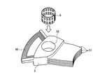
- FIG. 1 is a perspective view showing a schematic configuration of a hard disk device according to an embodiment of the present invention.
- FIG. 2 is a partial cross-sectional view showing a configuration of a main part of the hard disk device shown in FIG.
- FIG. 3 is a perspective view showing a configuration of a main part of the hard disk device shown in FIG.
- FIG. 4 is a perspective view showing a configuration of a tolerance ring of the hard disk device shown in FIG.
- FIG. 5 is a side view showing the configuration of the tolerance ring of the hard disk device shown in FIG.
- FIG. 6 is a schematic diagram showing the configuration of the tolerance ring of the hard disk device shown in FIG.
- FIG. 7 is a flowchart showing an example of the manufacturing method of the tolerance ring according to the embodiment of the present invention.
- FIG. 8 is a schematic diagram for explaining the manufacturing process shown in FIG.
- FIG. 9 is a schematic diagram illustrating the manufacturing process shown in FIG.
- FIG. 10 is a schematic diagram illustrating the manufacturing process shown in FIG.
- FIG. 11 is a schematic diagram illustrating the manufacturing process shown in FIG.
- FIG. 12 is a schematic diagram illustrating the manufacturing process shown in FIG.
- FIG. 13 is a schematic view showing a tolerance ring manufacturing method according to the embodiment of the present invention.
- FIG. 14 is a perspective view showing a schematic configuration of a conventional hard disk device.
- FIG. 1 is a perspective view showing a schematic configuration of a hard disk device according to an embodiment of the present invention.
- the hard disk device 1 shown in FIG. 1 has a drive mechanism housed in a casing body 2.
- the drive mechanism supports a hard disk 3 that is a recording medium, a spindle 4 that rotationally drives the hard disk 3, and a magnetic head unit 50 that records information on and reads information from the hard disk 3, and rotates on the surface of the hard disk 3.
- It has a carriage 5, a VCM 6 that controls the scanning of the magnetic head unit 50 by precisely rotating the carriage 5, and a columnar pivot shaft 7 that is fixed to the casing body 2 and connects the carriage 5.
- the pivot shaft 7 has a substantially columnar shape, for example, and has a bearing configuration.
- FIG. 2 is a partial cross-sectional view showing a configuration of a main part of the hard disk device 1 shown in FIG.
- FIG. 3 is a perspective view showing a configuration of a main part of the hard disk device 1 shown in FIG.
- the carriage 5 extends on the surface of the hard disk 3 and is connected to the arm 51 that holds the magnetic head unit 50 at the tip and the pivot shaft 7, and has a columnar hollow space whose cross section is slightly larger than the diameter of the cross section of the pivot shaft 7.
- a connecting part 52 having As shown in FIG. 2, the magnetic head unit 50 includes a suspension 50 a that floats with respect to the surface of the hard disk 3 by an air flow caused by the rotation of the hard disk 3, and an end of the suspension 50 a that is connected to the arm 51.
- a magnetic head 50b that is provided at an end portion on a different side and performs information recording and information reading.
- the VCM 6 includes a coil 60 connected to an end side different from the arm 51 side, and two magnets 61 sandwiching the coil 60.
- the VCM 6 drives the carriage 5 with a force generated by a current flowing through the coil 60 and a magnetic field. As a result, the carriage 5 is rotated on the surface of the hard disk 3 around the center of the pivot shaft 7 by the power from the VCM 6, and the magnetic head unit 50 is rotated on the surface of the hard disk 3.
- a tolerance ring 8 is used for fixing between the carriage 5 and the pivot shaft 7.
- the tolerance ring 8 is inserted into the hollow space of the connecting portion 52 of the carriage 5, and the pivot shaft 7 is press-fitted therein, thereby fixing between the carriage 5 and the pivot shaft 7.
- the carriage 5 is fixed so as to be rotatable around the central axis in the longitudinal direction of the pivot shaft 7 which is a bearing.
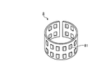
- FIG. 4 is a perspective view showing the configuration of the tolerance ring.
- FIG. 5 is a side view showing the configuration of the tolerance ring.
- the tolerance ring 8 is formed using plate-shaped stainless steel, has a ring shape that circulates substantially along a predetermined direction, and is provided with a plurality of convex portions 81.
- the convex portion 81 projects in a substantially rectangular shape in the radial direction on the outer surface of the tolerance ring 8.
- the convex portions 81 are provided in two rows along the circumferential direction of the tolerance ring 8.
- the convex portion 81 is pressed against the inner wall surface of the connecting portion 52 of the carriage 5, and the carriage 5 and the pivot shaft 7 are fixed.
- the length of the tolerance ring 8 in the circumferential direction is preferably equal to the length of the outer periphery of the opening of the connecting portion 52.
- the tolerance ring 8 has different values of the radius of curvature of the end portions 82 and 83 in the circumferential direction and the radius of curvature of portions other than the end portions 82 and 83 in the circumferential direction.
- the radius of curvature of the end portions 82 and 83 in the circumferential direction is equal to the radius of curvature of the connecting portion 52 of the carriage 5.
- the radius of curvature of the portion other than the end portions 82 and 83 in the circumferential direction is larger than the radius of curvature of the connecting portion 52 of the carriage 5.
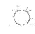
- a broken line P 0 indicates a circular shape with a radius of curvature of a portion other than the end portions 82 and 83 in the circumferential direction.
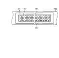
- FIG. 6 is a schematic diagram in which the tolerance ring 8 of the hard disk device 1 according to the present embodiment is extended in the circumferential direction.
- a description will be given assuming that 12 convex portions 81 are arranged in a row.
- the convex portions 81 of the tolerance ring 8 are arranged in two rows along the longitudinal direction of the main surface.
- the number of convex portions 81 arranged in a line is an even number, and the number of convex portions 81 is a multiple of three.
- the convex portion 81 is not disposed at a position that bisects in the circumferential direction when the tolerance ring 8 is manufactured, so that it can be easily curved and has a desired R shape. Easy to make. Further, by arranging the multiple convex portions 81 in multiples of 3, the contact is made so as to be symmetrical with respect to the contact side surface by 120 °, the load applied to the side surface of the connecting portion 52 is made substantially uniform, and the operation efficiency of the bearing is increased. High accuracy can be maintained.
- the convex portion is arranged at a position that bisects in the circumferential direction (the number of convex portions 81 arranged in a row is an odd number), the rigidity of the region of the convex portion located in the curved portion is increased, Since the springback is generated by the reaction force in the direction opposite to the bending direction, it is difficult to form a desired R shape.
- the radius of curvature of the end portions 82 and 83 in the circumferential direction is equal to the radius of curvature of the connecting portion 52 of the carriage 5 and the portions other than the end portions 82 and 83 in the circumferential direction.
- the tolerance ring 8 is held inside the connecting portion 52 when inserted into the connecting portion 52 of the carriage 5, and the circumferential direction of the tolerance ring 8 is The shape can be a circle along the wall surface of the connecting portion 52. For this reason, when the tolerance ring 8 is inserted into the connecting portion 52 of the carriage 5, it can be inserted without damaging the wall surface of the connecting portion 52. Therefore, the occurrence of contamination due to insertion of the tolerance ring can be suppressed.
- the shape along the circumferential direction when inserted into the connecting portion is an ellipse. Therefore, when the pivot shaft or the like is press-fitted into the tolerance ring, the side surface of the pivot shaft is the ellipse of the tolerance ring. There was a risk that the outer edge of the tolerance ring and / or the side surface of the pivot shaft may be damaged due to contact with the outer edge on the minor axis side of the shape, causing contamination.
- the tolerance ring according to the present embodiment has a circular shape along the wall surface of the connecting portion 52, the shape along the circumferential direction damages the wall surface of the connecting portion 52 when inserted into the connecting portion 52. You can insert without.
- the pivot shaft 7 when the pivot shaft 7 is press-fitted, the pivot shaft can be press-fitted without damaging the inner peripheral surface of the tolerance ring 8 and / or the side surface of the pivot shaft. Therefore, the occurrence of contamination due to tolerance ring can be suppressed.
- the tolerance ring 8 can easily press-fit the pivot shaft 7 into the tolerance ring 8, and can pivot the carriage 5 and the pivot 5 by pressing against the wall surface of the connecting portion 52 of the convex portion 81.
- the space between the shaft 7 can be securely fixed.
- the number of the convex portions 81 arranged in a line of the tolerance ring 8 described above is an even number and an integer number that is a multiple of three. Also good.
- the shape of the convex portion 81 has been described as projecting in a substantially rectangular shape from the outer surface, but the outer edge shape in the projecting direction forms a substantially circular shape as long as the above-mentioned number is satisfied and the members can be fixed between them.
- the outer edge shape of the protruding region from the outer surface may be substantially circular.
- the convex part 81 was demonstrated as what is provided in two rows along the circumference
- the above-described tolerance ring has been described as being curved so that the radius of curvature decreases continuously (in a multistage manner) in the direction from the portion other than the end portion toward the end portions 82 and 83, the end portion
- the radius of curvature and the radius of curvature of the portion other than the end may be curved in two stages.
- FIG. 7 is a flowchart showing an example of the manufacturing method of the tolerance ring according to the embodiment of the present invention.
- 8 to 12 are schematic views for explaining the manufacturing process shown in FIG.
- a contouring process is performed on the base material 100 extending in a flat plate shape by pressing (step S102: contouring step).
- step S102 contouring step
- the outer shape (outer edge) of the tolerance ring 8 is formed by this outer shape processing, and the base material 84 forming the outer shape of the tolerance ring 8 is formed.
- the connection state between the base material 84 and the base material 100 is maintained by the runner 101.
- the convex portion 81 is formed on the base material 84 formed in step 102 (step S104: forming step). As shown in FIG. 9, the convex portions 81 are respectively formed at the positions described above by pressing. At this time, the convex part 81 is shape
- FIG. 11 is a schematic view of the substrate 84 shown in FIG. 10 as viewed from the direction of arrow A.
- the base member 84 is bent stepwise from both ends along the longitudinal direction of the main surface of the base member 84 so that the convex portion 81 is on the outer surface side, and the end portions 82 and 83 in the circumferential direction are formed. Is made smaller than the radius of curvature of the portion other than the end portions 82 and 83 in the circumferential direction (see FIGS. 10 and 11).
- the base material 84 is curved so that the radius of curvature decreases continuously (multistagely) in the direction from the portion other than the end portions 82 and 83 toward the end portions 82 and 83.
- step S108 trimming process
- the tolerance ring 8 can be obtained by cutting off the base material 84 from the runner 101.
- a process (setting process) for applying a stress that is equal to or greater than the maximum usable stress may be performed on the protrusion 81 of the obtained tolerance ring 8.
- the setting process is preferably performed between the forming process of the convex portion 81 in step S104 and the bending process in step S106 and before the base material 84 is bent.
- the manufacturing method of the tolerance ring 8 described above can be realized by a progressive press that sequentially performs the above-described process on the base material 100 extending in a strip shape as shown in FIG. Thereby, the tolerance ring 8 can be efficiently produced using one apparatus.
- the tolerance ring and the tolerance ring manufacturing method according to the present invention can be easily press-fitted into a press-fitting object, and are useful for suppressing the occurrence of contamination.
Landscapes
- Engineering & Computer Science (AREA)
- General Engineering & Computer Science (AREA)
- Mechanical Engineering (AREA)
- Moving Of Heads (AREA)
- Support Of The Bearing (AREA)
- Mounting Of Bearings Or Others (AREA)
- Endoscopes (AREA)
- Straightening Metal Sheet-Like Bodies (AREA)
Abstract
Description
2,201 ケーシング本体
3,202 ハードディスク
4,203 スピンドル
5,205 キャリッジ
6,206 VCM
7,207 ピボット軸
8 トレランスリング
50 磁気ヘッド部
50a サスペンション
50b,204 磁気ヘッド
51 アーム
52 連結部
60 コイル
61 磁石
81 凸部
82,83 端部
100 母材
101 ランナー
Claims (5)
- 所定方向に沿って略周回するリング状をなし、複数の凸部が設けられたトレランスリングであって、
周回方向における端部の曲率半径が、前記周回方向における前記端部以外の部分の曲率半径より小さいことを特徴とするトレランスリング。 - 前記端部以外の部分から前記端部に向かう方向に従って連続的に曲率半径が小さくなることを特徴とする請求項1に記載のトレランスリング。
- 前記複数の凸部は、前記周回方向に沿って配置され、
前記周回方向に沿って配置される前記凸部のうち、一列に配置される前記凸部の個数は、偶数であることを特徴とする請求項1または2に記載のトレランスリング。 - 前記一列に配置される前記凸部の個数は、3の倍数であることを特徴とする請求項3に記載のトレランスリング。
- 挿入対象の部材間に配置され、該部材間を固定するトレランスリングの製造方法であって、
順送される帯状の母材に対して、ランナーで連結された当該トレランスリングの外形を形取ることによって基材を成形する外形取りステップと、
前記外形取りステップによって成形された基材に対して凸部を成形する成形ステップと、
前記凸部が成形された前記基材の周回方向における端部の曲率半径が、前記端部以外の部分の曲率半径と比して小さくなるように前記基材を段階的に湾曲させる湾曲ステップと、
前記湾曲ステップによって湾曲された前記基材に対して前記ランナーから切り落として当該トレランスリングをトリミングするトリミングステップと、
を含むことを特徴とするトレランスリングの製造方法。
Priority Applications (4)
| Application Number | Priority Date | Filing Date | Title |
|---|---|---|---|
| US14/112,689 US9429190B2 (en) | 2011-04-22 | 2012-04-20 | Tolerance ring and method of manufacturing tolerance ring |
| EP12773565.2A EP2700833A4 (en) | 2011-04-22 | 2012-04-20 | TOLERANCED RING AND METHOD FOR MANUFACTURING A TOLERANCED RING |
| JP2013511071A JP5787987B2 (ja) | 2011-04-22 | 2012-04-20 | トレランスリングおよびトレランスリングの製造方法 |
| CN201280019776.7A CN103492734B (zh) | 2011-04-22 | 2012-04-20 | 公差环及公差环的制造方法 |
Applications Claiming Priority (2)
| Application Number | Priority Date | Filing Date | Title |
|---|---|---|---|
| JP2011096409 | 2011-04-22 | ||
| JP2011-096409 | 2011-04-22 |
Publications (1)
| Publication Number | Publication Date |
|---|---|
| WO2012144628A1 true WO2012144628A1 (ja) | 2012-10-26 |
Family
ID=47041728
Family Applications (1)
| Application Number | Title | Priority Date | Filing Date |
|---|---|---|---|
| PCT/JP2012/060780 WO2012144628A1 (ja) | 2011-04-22 | 2012-04-20 | トレランスリングおよびトレランスリングの製造方法 |
Country Status (5)
| Country | Link |
|---|---|
| US (1) | US9429190B2 (ja) |
| EP (1) | EP2700833A4 (ja) |
| JP (1) | JP5787987B2 (ja) |
| CN (1) | CN103492734B (ja) |
| WO (1) | WO2012144628A1 (ja) |
Cited By (3)
| Publication number | Priority date | Publication date | Assignee | Title |
|---|---|---|---|---|
| WO2014123166A1 (ja) * | 2013-02-05 | 2014-08-14 | 日本発條株式会社 | トレランスリングおよびハードディスク装置 |
| JP2016510384A (ja) * | 2012-12-31 | 2016-04-07 | サン−ゴバン パフォーマンス プラスティックス レンコール リミティド | 離散トレランス・リング・パネルを含むトレランス・リング |
| JP2022515423A (ja) * | 2018-12-31 | 2022-02-18 | サン-ゴバン パフォーマンス プラスティックス レンコール リミティド | トレランスリング、アセンブリ、ならびにその作製および使用方法 |
Families Citing this family (3)
| Publication number | Priority date | Publication date | Assignee | Title |
|---|---|---|---|---|
| US10094426B2 (en) * | 2013-06-27 | 2018-10-09 | Saint-Gobain Performance Plastics Rencol Limited | Tolerance ring with divided torque slip |
| US10100873B2 (en) * | 2014-12-09 | 2018-10-16 | Ford Global Technologies, Llc | Radially deflectable bushing and steering gear assembly using the same |
| CN115899061A (zh) * | 2022-11-30 | 2023-04-04 | 重庆长安汽车股份有限公司 | 一种轴瓦配瓦的方法、装置及电子设备 |
Citations (5)
| Publication number | Priority date | Publication date | Assignee | Title |
|---|---|---|---|---|
| JPH05205413A (ja) | 1991-07-12 | 1993-08-13 | Seagate Technol Internatl | ピボット機構 |
| JPH0828554A (ja) * | 1994-07-18 | 1996-02-02 | Daido Metal Co Ltd | ブッシュ |
| JP2002130310A (ja) | 2000-10-20 | 2002-05-09 | Nsk Ltd | ユニット軸受 |
| JP2003522912A (ja) | 2000-02-09 | 2003-07-29 | シーゲイト テクノロジー エルエルシー | 変形しにくい高フープ強度を有する公差リング |
| JP2007305268A (ja) | 2006-05-15 | 2007-11-22 | Nsk Ltd | 軸受ユニット |
Family Cites Families (12)
| Publication number | Priority date | Publication date | Assignee | Title |
|---|---|---|---|---|
| US1662544A (en) * | 1926-03-01 | 1928-03-13 | Simplex Piston Ring Company | Piston ring |
| US3061386A (en) * | 1961-10-04 | 1962-10-30 | Star Kugelhalter Gmbh Dt | Tolerance rings |
| IT984360B (it) | 1972-03-06 | 1974-11-20 | Star Kugelhalter Gmbh Dt | Elemento di inserto interponibile tra organi di macchine a scopo di collegamento |
| JPS5421900B2 (ja) * | 1973-02-15 | 1979-08-02 | ||
| US4119874A (en) * | 1977-02-11 | 1978-10-10 | Borg-Warner Corporation | Bearing arrangement for elongated electric motors |
| US4286894A (en) * | 1979-03-21 | 1981-09-01 | Roller Bearing Company Of America | Tolerance rings |
| DE4109481C2 (de) | 1991-03-22 | 1994-01-13 | Loehr & Bromkamp Gmbh | Sprengring |
| FR2698938B1 (fr) * | 1992-12-07 | 1995-03-10 | Valeo | Amortisseur de torsion, notamment pour véhicule automobile. |
| US20070110351A1 (en) * | 2005-11-16 | 2007-05-17 | Honeywell International, Inc. | Centering mechanisms for turbocharger bearings |
| US8233242B2 (en) * | 2007-04-24 | 2012-07-31 | Saint-Gobain Performance Plastics Rencol Limited | Tolerance ring with overlapping layers |
| EP2218070B1 (en) * | 2007-11-15 | 2012-06-06 | Intri-Plex Technologies, Inc. | Tolerance ring for data storage with overlapping tab feature for mass control |
| US20110076096A1 (en) * | 2009-09-25 | 2011-03-31 | Saint-Gobain Performance Plastics Rencol Limited | System, method and apparatus for tolerance ring control of slip interface sliding forces |
-
2012
- 2012-04-20 US US14/112,689 patent/US9429190B2/en active Active
- 2012-04-20 CN CN201280019776.7A patent/CN103492734B/zh not_active Expired - Fee Related
- 2012-04-20 JP JP2013511071A patent/JP5787987B2/ja active Active
- 2012-04-20 WO PCT/JP2012/060780 patent/WO2012144628A1/ja active Application Filing
- 2012-04-20 EP EP12773565.2A patent/EP2700833A4/en not_active Withdrawn
Patent Citations (5)
| Publication number | Priority date | Publication date | Assignee | Title |
|---|---|---|---|---|
| JPH05205413A (ja) | 1991-07-12 | 1993-08-13 | Seagate Technol Internatl | ピボット機構 |
| JPH0828554A (ja) * | 1994-07-18 | 1996-02-02 | Daido Metal Co Ltd | ブッシュ |
| JP2003522912A (ja) | 2000-02-09 | 2003-07-29 | シーゲイト テクノロジー エルエルシー | 変形しにくい高フープ強度を有する公差リング |
| JP2002130310A (ja) | 2000-10-20 | 2002-05-09 | Nsk Ltd | ユニット軸受 |
| JP2007305268A (ja) | 2006-05-15 | 2007-11-22 | Nsk Ltd | 軸受ユニット |
Non-Patent Citations (1)
| Title |
|---|
| See also references of EP2700833A4 |
Cited By (5)
| Publication number | Priority date | Publication date | Assignee | Title |
|---|---|---|---|---|
| JP2016510384A (ja) * | 2012-12-31 | 2016-04-07 | サン−ゴバン パフォーマンス プラスティックス レンコール リミティド | 離散トレランス・リング・パネルを含むトレランス・リング |
| JP2017215044A (ja) * | 2012-12-31 | 2017-12-07 | サン−ゴバン パフォーマンス プラスティックス レンコール リミティド | 離散トレランス・リング・パネルを含むトレランス・リング |
| WO2014123166A1 (ja) * | 2013-02-05 | 2014-08-14 | 日本発條株式会社 | トレランスリングおよびハードディスク装置 |
| JP2022515423A (ja) * | 2018-12-31 | 2022-02-18 | サン-ゴバン パフォーマンス プラスティックス レンコール リミティド | トレランスリング、アセンブリ、ならびにその作製および使用方法 |
| JP7193645B2 (ja) | 2018-12-31 | 2022-12-20 | サン-ゴバン パフォーマンス プラスティックス レンコール リミティド | トレランスリング、アセンブリ、ならびにその作製および使用方法 |
Also Published As
| Publication number | Publication date |
|---|---|
| US20140147199A1 (en) | 2014-05-29 |
| JP5787987B2 (ja) | 2015-09-30 |
| EP2700833A4 (en) | 2015-03-11 |
| US9429190B2 (en) | 2016-08-30 |
| CN103492734A (zh) | 2014-01-01 |
| EP2700833A1 (en) | 2014-02-26 |
| CN103492734B (zh) | 2016-03-02 |
| JPWO2012144628A1 (ja) | 2014-07-28 |
Similar Documents
| Publication | Publication Date | Title |
|---|---|---|
| JP5787987B2 (ja) | トレランスリングおよびトレランスリングの製造方法 | |
| JP6040167B2 (ja) | トレランスリング | |
| JP5781628B2 (ja) | トレランスリング、ハードディスク装置およびハードディスク装置の製造方法 | |
| US20130335859A1 (en) | Base plate, base unit, motor and disk drive apparatus | |
| US8878416B2 (en) | Stator core and motor device including the same | |
| JP7123261B2 (ja) | 回転電機のロータ及びその製造方法 | |
| KR100737531B1 (ko) | 스핀들 모터의 턴테이블 | |
| JP6047106B2 (ja) | トレランスリングおよびハードディスク装置の製造方法 | |
| JP5553641B2 (ja) | 着磁装置および回転機器の製造方法 | |
| US20170011761A1 (en) | Tolerance ring and hard disk device | |
| WO2013172313A1 (ja) | トレランスリング | |
| WO2014123166A1 (ja) | トレランスリングおよびハードディスク装置 | |
| JP6001504B2 (ja) | ロータ体 | |
| JP2007265537A (ja) | ディスク回転駆動装置及びそのディスク取付方法、スプリング・ワッシャ |
Legal Events
| Date | Code | Title | Description |
|---|---|---|---|
| 121 | Ep: the epo has been informed by wipo that ep was designated in this application |
Ref document number: 12773565 Country of ref document: EP Kind code of ref document: A1 |
|
| ENP | Entry into the national phase |
Ref document number: 2013511071 Country of ref document: JP Kind code of ref document: A |
|
| NENP | Non-entry into the national phase |
Ref country code: DE |
|
| WWE | Wipo information: entry into national phase |
Ref document number: 2012773565 Country of ref document: EP |
|
| WWE | Wipo information: entry into national phase |
Ref document number: 14112689 Country of ref document: US |