WO2014119774A1 - フットウエア用ソール構造体 - Google Patents
フットウエア用ソール構造体 Download PDFInfo
- Publication number
- WO2014119774A1 WO2014119774A1 PCT/JP2014/052373 JP2014052373W WO2014119774A1 WO 2014119774 A1 WO2014119774 A1 WO 2014119774A1 JP 2014052373 W JP2014052373 W JP 2014052373W WO 2014119774 A1 WO2014119774 A1 WO 2014119774A1
- Authority
- WO
- WIPO (PCT)
- Prior art keywords
- sole
- protrusion
- sole structure
- protrusions
- foot
- Prior art date
- Legal status (The legal status is an assumption and is not a legal conclusion. Google has not performed a legal analysis and makes no representation as to the accuracy of the status listed.)
- Ceased
Links
Images


Classifications
-
- A—HUMAN NECESSITIES
- A43—FOOTWEAR
- A43B—CHARACTERISTIC FEATURES OF FOOTWEAR; PARTS OF FOOTWEAR
- A43B13/00—Soles; Sole-and-heel integral units
- A43B13/14—Soles; Sole-and-heel integral units characterised by the constructive form
-
- A—HUMAN NECESSITIES
- A43—FOOTWEAR
- A43B—CHARACTERISTIC FEATURES OF FOOTWEAR; PARTS OF FOOTWEAR
- A43B13/00—Soles; Sole-and-heel integral units
- A43B13/14—Soles; Sole-and-heel integral units characterised by the constructive form
- A43B13/18—Resilient soles
- A43B13/181—Resiliency achieved by the structure of the sole
- A43B13/184—Resiliency achieved by the structure of the sole the structure protruding from the outsole
-
- A—HUMAN NECESSITIES
- A43—FOOTWEAR
- A43B—CHARACTERISTIC FEATURES OF FOOTWEAR; PARTS OF FOOTWEAR
- A43B3/00—Footwear characterised by the shape or the use
- A43B3/12—Sandals; Strap guides thereon
- A43B3/128—Sandals; Strap guides thereon characterised by the sole
-
- A—HUMAN NECESSITIES
- A43—FOOTWEAR
- A43B—CHARACTERISTIC FEATURES OF FOOTWEAR; PARTS OF FOOTWEAR
- A43B7/00—Footwear with health or hygienic arrangements
- A43B7/14—Footwear with health or hygienic arrangements with foot-supporting parts
- A43B7/1405—Footwear with health or hygienic arrangements with foot-supporting parts with pads or holes on one or more locations, or having an anatomical or curved form
- A43B7/1455—Footwear with health or hygienic arrangements with foot-supporting parts with pads or holes on one or more locations, or having an anatomical or curved form with special properties
- A43B7/146—Footwear with health or hygienic arrangements with foot-supporting parts with pads or holes on one or more locations, or having an anatomical or curved form with special properties provided with acupressure points or means for foot massage
-
- A—HUMAN NECESSITIES
- A43—FOOTWEAR
- A43B—CHARACTERISTIC FEATURES OF FOOTWEAR; PARTS OF FOOTWEAR
- A43B7/00—Footwear with health or hygienic arrangements
- A43B7/14—Footwear with health or hygienic arrangements with foot-supporting parts
- A43B7/1405—Footwear with health or hygienic arrangements with foot-supporting parts with pads or holes on one or more locations, or having an anatomical or curved form
- A43B7/1475—Footwear with health or hygienic arrangements with foot-supporting parts with pads or holes on one or more locations, or having an anatomical or curved form characterised by the type of support
Definitions
- the present invention relates to a sole structure for footwear including shoes, sandals, boots, and the like, and more specifically, information from the road surface acting on the bottom surface of the sole (reaction force from the road surface, uneven state of the road surface, and the road surface)
- the present invention relates to a sole structure that can accurately transmit (contact area) to the sole of the wearer.
- Japanese Patent Publication No. 4-75001 discloses a structure in which a plurality of cylindrical rubber pieces or resin pieces are provided inside a grounded bottom main body. (See FIG. 1).
- the bent portion is made of a material having a low Young's modulus and hardness
- the ground pad is made of a material having a high Young's modulus and hardness
- the bent portion easily deforms, so that the ground pad easily moves upward
- the shape of the ground pad does not change, the force from the road surface is directly transmitted to the wearer's sole through the ground pad. Therefore, in the above-mentioned publication, the force from the road surface can be transmitted from the ground pad to the sole of the wearer, but the shape of the ground pad does not change, and the upper and lower surfaces of the ground pad are formed flat.
- the force from the road surface can be transmitted to the wearer's sole via the pressure stimulating member, but the force from the road surface is applied to the wearer's sole via the midsole. Since it is acting, information on the contact area with the road surface cannot be accurately transmitted to the wearer at the time of landing.
- a force from the road surface acts on the ground contact surface of the midsole during landing.
- the pushing member inside the midsole transmits the force from the road surface to the elastic protrusion as it is, and the elastic member inside the midsole transmits the force from the road surface to the elastic protrusion while partially absorbing the force. Therefore, in the above-mentioned publication, the push member and the elastic member are arranged inside the insole even though the force from the road surface can be transmitted to the wearer's sole via the push member and the elastic member. Therefore, the bottom surface of each of the push member and the elastic member and the top surface of the elastic protrusion are formed flat (this will be described later), so that information on the contact area with the road surface can be accurately given to the wearer at the time of landing. I can't tell you. In the sole structure shown in the above Japanese Patent Publication No.
- the present invention has been made in view of such a conventional situation, and the problem to be solved by the present invention is information from the road surface acting on the sole bottom surface (that is, reaction force from the road surface and uneven state of the road surface). It is an object of the present invention to provide a sole structure capable of accurately transmitting not only the contact area with the road surface) but also the sole of the wearer in an interlocked state.
- the sole structure for footwear according to the present invention includes a sole body having a bottom surface of the sole disposed on the road surface side and a sole top surface on the opposite side, and a plurality of first protrusions made of an elastic member provided on the bottom surface of the sole. And a plurality of second protrusions made of an elastic member provided at positions corresponding to the plurality of first protrusions on the upper surface of the sole.
- the cross-sectional shape of the first protrusion is formed so as to gradually decrease as the distance from the bottom surface of the sole is increased, and the tip of the first protrusion has a convex surface protruding downward.
- the cross-sectional shape of the second protrusion is formed so as to gradually decrease as the distance from the upper surface of the sole increases, and the tip of the second protrusion has a convex surface protruding upward.
- the concave / convex shape formed by the plurality of second protrusions on the upper surface of the sole defines the concave / convex shape of the foot contact surface of the wearer in the footwear (see claim 1).
- the force acting on the sole structure from the road surface is transmitted from the first protrusion on the lower surface side of the sole to the second protrusion on the upper surface side of the sole via the sole body,
- protrusion the information of the force from a road surface is conveyed to a wearer's sole.
- the distribution of the force acting on the first protrusion from the road surface changes according to the uneven state of the road surface, and the change state is transmitted to the second protrusion through the sole body.
- the protrusions 2 information on the unevenness of the road surface is transmitted to the soles of the wearers.
- the first protrusion has a convex surface formed such that the cross-sectional shape gradually decreases as the distance from the bottom surface of the sole increases, and the tip of the first protrusion protrudes downward.
- the cross-sectional shape of the second protrusion is formed so as to gradually decrease as the distance from the upper surface of the sole increases, and the tip of the second protrusion has a convex surface protruding upward, the road surface when landing As the force acting on the first protrusion increases, the contact area of the first protrusion with the road surface increases, and the second protrusion corresponding to the first protrusion from the sole of the wearer when landing. As the applied force increases, the contact area of the second protrusion with the sole increases.
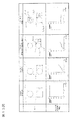
- FIG. 15 shows the result of the analysis to see the effect of the present invention.
- each protrusion structure is dropped freely from a certain height downward with a weight of a certain weight placed on the upper surface of each protrusion structure.
- each protruding structure exerts on the drop surface (grounding surface) (in other words, the reaction force that acts on the lower surface of each protruding structure from the grounding surface) and the contact with the grounding surface of each protruding structure
- FEM finite element method
- the weight placed on the upper surface of each protrusion structure corresponds to the sole body of the present invention.
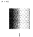
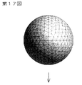
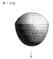
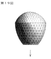
- the more detailed shape (side surface shape) of each protrusion structure divided into elements is shown in FIGS. 16 to 19, and a downward arrow indicates the dropping direction in each figure.
- the specific dimensions of each protrusion structure are shown in the upper column of FIG.
- the analysis conditions of the finite element method are as follows.
- each protrusion structure was 1 g
- the weight of the weight placed on the upper surface of each protrusion structure was 256 g
- the total weight of both was 257 g.
- the height of the drop that is, the height from the drop surface to the lower surface of each protrusion structure was set to 7.7 mm.
- the analysis results for each protrusion structure are shown in the lower graph of FIG.
- the horizontal axis indicates the reaction force (kg)
- the vertical axis indicates the contact area (mm 2 ). Looking at each graph, if the bottom surface of the projection is flat, such as the cylindrical projection of sample 1 or the projection of sample 4, the contact area with the ground plane is almost constant even if the reaction force from the ground plane increases.
- the bottom surface of the sole structure is formed flat, or in the sole structure described in JP 2009-172183 A, the bottom surface is It can be said that the pressing member and the elastic member formed flat correspond to these samples 1 or 4.
- the bottom surface has a convex surface (more specifically, the bottom surface has a convex curved surface, an arcuate surface, or a spherical surface) and goes toward the bottom surface.
- the contact area with the ground contact surface increases as the reaction force from the ground contact surface increases, and the contact information with the force from the ground contact surface increases. It can be seen that the information on the contact area with the ground is accurately linked. Therefore, as in the present invention, the tip of the first protrusion has a convex surface protruding downward, and the cross-sectional shape of the first protrusion gradually decreases as the distance from the bottom surface of the sole increases. In this case, the contact area with the road surface increases as the reaction force from the road surface increases, and the information on the reaction force from the road surface and the information on the contact area with the road surface are accurately linked.
- the tip end portion of the second protrusion provided at a position corresponding to the first protrusion on the upper surface of the sole has a convex surface protruding upward
- the cross-sectional shape of the second protrusion Is formed so as to gradually decrease as the distance from the upper surface of the sole increases, the contact area between the first protrusion and the road surface increases as the force acting on the first protrusion from the road surface during landing increases.
- the contact area of the second projection with the sole increases, thereby increasing the road surface. The information on the contact area is accurately transmitted to the sole of the wearer.
- the first and second protrusions are compressed and deformed, and the contact area between the first protrusion and the road surface increases as the load on the first protrusion increases. As the contact area increases, the contact area between the second protrusion and the wearer's foot increases (see claim 2).
- the tip end portion of the first protrusion has a downwardly convex curved surface shape
- the tip end portion of the second protrusion has an upwardly convex curved surface shape. reference).
- the tip of the first or second protrusion is formed of an arcuate surface composed of a single arc or a plurality of arcs (see claim 4).
- the angle formed by the outer surface of the first protrusion with respect to the lower surface of the sole is an obtuse angle
- the angle formed by the outer surface of the second protrusion with respect to the upper surface of the sole is obtuse (see claim 5).
- the tip of the second protrusion is provided so as to directly contact the bottom surface of the upper part of the footwear, or the footwear contact surface of the wearer is directly configured in the footwear. (See claim 6).
- the wearer's sole contact surface is formed by the bottom surface of the upper portion.
- the outer peripheral edge of the upper part is sewn to the outer peripheral edge of the sole structure or This corresponds to footwear such as shoes in which the bottom surface is not provided on the upper part or sandals in which the upper part is not provided by being fixed by bonding or the like.
- the hardness of the first protrusion is higher than the hardness of the second protrusion (see claim 7). This relatively increases the hardness of the first protrusion in contact with the road surface to improve the wear resistance of the first protrusion, and the second protrusion disposed on the sole contact surface side of the wearer. This is because the hardness of the protrusion is relatively lowered to improve the foot contact when worn.
- a cavity is formed inside the first or second protrusion (see claim 8).
- the first and second protrusions are provided in the forefoot region and the middle foot region of the sole structure, that is, the region excluding the buttocks in the sole structure (see claim 9). This is because, particularly in sports shoes, a large impact force acts on the buttocks at the time of landing, so that excessive pressure acts on the buttocks due to the projections.
- the distance between the adjacent first protrusions and the distance between the adjacent second protrusions are greater in the front foot rear region and the middle foot region than in the front foot front region of the sole structure. It is larger (see claim 10).
- the distance between the first projections adjacent to each other in the front foot rear region and the middle foot region of the sole structure and the interval between the adjacent second projections are determined by the feet of the sole structure.
- the foot length direction is larger than the width direction (see claim 11).
- each subject area was stimulated with the tip of the toothpick while blindfolded on the subject.
- interval of two toothpicks was performed about two directions, a foot width direction and a foot length direction.
- the subject answers whether the stimulus given to the sole is due to one or two toothpick.
- the interval between the two toothpicks is gradually increased on the scale, and when the stimulation by the two toothpicks can be identified three times in succession.
- the test subject determined that two toothpicks could be detected, otherwise the test subject determined that two toothpicks could not be detected.
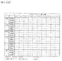
- the experimental results are shown in FIG. In the figure, the left column shows each area of the subject's sole (thumb, middle finger, thumb ball part, middle foot part, arch part, buttocks). The experiment was performed on three subjects A to C. Further, in the same figure, the upper column shows the interval between each toothpick in the case of two conditions using two toothpicks.
- a circle indicates that the subject was able to detect two toothpicks in both the foot width direction and the foot length direction, and a ⁇ mark was that the subject was able to detect two toothpick in the foot width direction.
- ⁇ indicates that the subject was able to detect two toothpicks in the foot width direction but not in the foot length direction, and ⁇ indicates the experiment Is not implemented.
- the distance between the two toothpicks is If it is 8 mm to 12 mm apart, all the subjects A to C can detect two toothpicks in both the foot width direction and the foot length direction, whereas in the case of the middle foot part and the arch part, 2 If the distance between the toothpick is 16 mm to 18 mm, all the subjects A to C can detect the two toothpicks in both the foot width direction and the foot length direction.
- the subjects A and B can detect the two toothpicks in the foot width direction and the foot length direction. From this, the subject can detect each toothpick in the forefoot front region of the sole even if the distance between the two toothpicks is relatively narrow, and the forefoot rear region (including the toe ball part) and the middle foot In the partial area, it can be said that each toothpick cannot be detected unless the distance between the two toothpick is relatively wide.
- the invention of claim 10 has been made in view of such an experimental result, and the distance between the adjacent first protrusions and the distance between the adjacent second protrusions are determined based on the front foot front region of the sole structure.
- the first and second protrusions have a circular shape in the front foot front region of the sole structure as viewed from the bottom surface side and the plane side, and extend from the front foot rear region to the middle foot region.
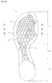
- FIG. 1 is a bottom view of a sole structure for sports shoes according to an embodiment of the present invention.
- FIG. 2 is a plan view of the sole structure of FIG.
- FIG. 3 is a cross-sectional view taken along line III-III in FIG.
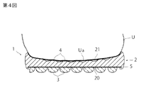
- FIG. 4 is a sectional view taken along line IV-IV in FIG.
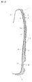
- FIG. 5 is a cross-sectional view taken along line VV in FIG.
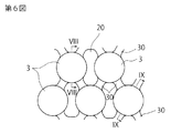
- FIG. 6 is a partially enlarged view of the front foot front region of the sole structure shown in FIG.
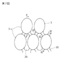
- FIG. 7 is a partially enlarged view of the midfoot region of the sole structure of FIG.
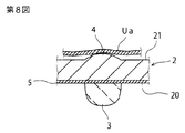
- FIG. 8 is a sectional view taken along line VIII-VIII in FIG.
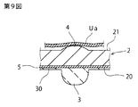
- FIG. 9 is a sectional view taken along line IX-IX in FIG.
- FIG. 1 is a bottom view of a sole structure for sports shoes according to an embodiment of the present invention.
- FIG. 2 is a plan view of the sole structure of FIG.
- FIG. 3 is a cross-sectional
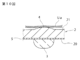
- FIG. 10 is a sectional view taken along line XX of FIG. 11 is a cross-sectional view taken along line XI-XI in FIG.
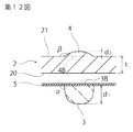
- FIG. 12 is a partially enlarged cross-sectional view for explaining the assembly method of the sole structure shown in FIG.
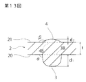
- FIG. 13 is a partially enlarged sectional view showing a modification of the sole structure shown in FIG.
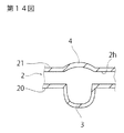
- FIG. 14 is a partially enlarged cross-sectional view showing another modified example of the sole structure shown in FIG.
- FIG. 15 is a diagram for explaining an analysis method for seeing the effects of the present invention and the result thereof.
- FIG. 16 is a side view of the protrusion structure of sample 1 used in the analysis of FIG.
- FIG. 17 is a side view of the protruding structure of sample 2 used in the analysis of FIG. FIG.
- FIG. 18 is a side view of the protruding structure of sample 3 used in the analysis of FIG.
- FIG. 19 is a side view of the protruding structure of sample 4 used in the analysis of FIG.
- FIG. 20 is a diagram showing the results of a two-point discrimination threshold experiment for investigating the ability to sense a human foot sole.
- FIGS. 1 to 12 show a sole structure for sports shoes according to an embodiment of the present invention.
- “upper”, “lower”, “front”, and “rear” mean the upper, lower, front, and rear of the shoe, respectively. That is, the upper and lower parts indicate the upper and lower parts of FIG. 3 and FIG. 4, respectively, and the front and rear parts are the same when FIG. 1 is taken as an example.
- H indicates a heel portion of the sole structure
- M indicates a middle foot portion
- F indicates a forefoot portion.
- the sole structure 1 has a sole body 2 made of an elastic member that extends from the heel H to the front foot F through the middle foot M.
- the sole body 2 has a sole lower surface 20 disposed on the road surface side (lower side in FIGS. 3 and 4) and a sole upper surface 21 disposed on the sole contact side on the opposite side.
- the sole lower surface 20 is provided with a plurality of first protrusions 3 made of an elastic member
- the sole upper surface 21 is similarly provided with a plurality of second protrusions 4 made of an elastic member.
- the first and second protrusions 3 and 4 are mainly provided on the front foot portion F and the middle foot portion M of the sole structure 1, and are not provided on the heel portion H.
- the plurality of first and second protrusions 3 and 4 are arranged at positions facing each other vertically with the sole body 2 interposed therebetween. Preferably, the center of each of the corresponding first and second protrusions coincides with the vertical direction.
- the plurality of first protrusions 3 are provided so as to be separated from each other without overlapping with the adjacent first protrusions 3.
- the plurality of second protrusions 4 are adjacent to the respective second protrusions. 4 are separated from each other without overlapping.
- the first and second protrusions 3 and 4 have a circular shape in a bottom view (and a plan view) in the front region of the front foot F of the sole structure 1, and the rear region (finger ball portion) of the front foot F From the middle foot portion to the middle foot portion, it has an oval shape in bottom view (and plan view) extending substantially in the front-rear direction (that is, the foot length direction) (see FIGS. 1 and 2).
- the major axis direction (direction of arrow a in FIG. 2) of the elliptical protrusions 3 and 4 is 5 ° on the outer side with respect to the front-rear direction (foot length direction) of the sole structure 1.
- the major axis direction of the oval projections 3 and 4 (in the direction of arrow b in the figure) is the front-rear direction (foot length) of the sole structure 1.
- Direction and inclined by -5 ° to 25 ° on the outer side (that is, 5 ° to the inner side and 25 ° to the outer side). This is because the shear direction with respect to the sole structure 1 during the running operation is taken into consideration.
- the distance between adjacent second protrusions 4, that is, the distance between the centers (the same applies to the distance between adjacent first protrusions 3 (the distance between the centers)), both for the width in the foot width direction and for the distance in the foot length direction.
- the distance in the rear region of the front foot F and the middle foot M is larger than the space in the front region of the front foot F. That is, as shown in FIG. 2, S 1 in the forefoot front region spacing feet width direction of the second projection 4 adjacent S 1, in the forefoot posterior region ', S 1 at midfoot M "a, S 2 in the forefoot front region spacing foot length direction S 2, in the forefoot posterior region ', S 2 at the midfoot M" when the, S 1 ′> S 1 , S 1 ′′> S 1 , S 2 ′> S 2 , S 2 ′′> S 2 It has become.
- the interval between the adjacent second protrusions 4 (the same applies to the interval between the adjacent first protrusions 3)
- the foot length direction is larger than the width direction. That is, as shown in FIG. S 2 ′> S 1 ′, S 2 ′′> S 1 ′′ It has become.
- the distance between the first and second protrusions 3 and 4 is adjusted based on the experimental result of the two-point discrimination threshold using the toothpick as described above.
- the cross-sectional shape of the first protrusion 3 is formed so as to gradually become smaller as the distance from the sole lower surface 20 increases.
- Has a convex surface in this example, a convex curved surface shape downward.
- the cross-sectional shape of the second protrusion 4 is formed so as to gradually become smaller as the distance from the sole upper surface 21 increases.
- the curved surfaces of the tip portions of the first and second protrusions 3 and 4 are composed of a plurality of arc-shaped surfaces composed of a plurality of arcs, even though they are composed of arc-shaped surfaces composed of a single arc. Also good.
- the tip of the second protrusion 4 is composed of a single arcuate surface having a large radius of curvature, and the tip of the first protrusion 3 is disposed at the center and has a large radius of curvature.
- the arc-shaped surface is composed of arc-shaped surfaces and arc-shaped surfaces having small curvature radii that are arranged on both sides of the arc-shaped surface and are connected to the side surfaces of the first protrusion 3.
- the protrusion amount of the second protrusion 4 from the sole upper surface 21 is smaller than the protrusion amount of the first protrusion 3 from the sole lower surface 20 (see FIGS. 3 to 5).
- the surface on the sole contact side of the body 1 has a concavo-convex shape with a low step, in which a convex portion formed by the second protrusion 4 and a concave portion formed by the sole upper surface 21 are combined.
- 3 to 5 show an example in which the upper portion U is provided on the sole structure 1 (only a portion of the upper portion U is shown in each figure).
- the bottom surface Ua of the part U is bonded to the distal end portion of the curved surface shape of the second protrusion 4.
- FIG. 1 In the sports shoes in which the sole structure 1 is employed, the insole is preferably not used, and the sole of the wearer directly comes into contact with the bottom surface Ua of the upper U portion. Yes.
- FIGS. 6 and 7 which are partially enlarged views of FIG. 1, the plurality of first protrusions 3 are formed between the first protrusions 3 adjacent in the oblique direction on the bottom surface 20 of the sole. Are connected to each other through a connecting portion 30 made of an elastic member. Although the first protrusion 3 is elastically supported in the vertical direction by the connecting portion 30, the connecting portion 30 is not an essential member.
- FIG. 6 and 7 which are partially enlarged views of FIG. 1
- the plurality of first protrusions 3 are formed between the first protrusions 3 adjacent in the oblique direction on the bottom surface 20 of the sole. Are connected to each other through a connecting portion 30 made of an elastic member. Although the first protrusion 3 is elastically supported in the vertical direction by the connecting portion 30, the connecting portion 30 is not an essential member
- the forefoot F has a region g in which the connecting portion 30 is not provided extending in the foot width direction, and this region g corresponds to the position of the middle foot ankle joint joint. And by not providing the connection part 30, the said area
- FIG. 8 FIG. 9, FIG. 10, and FIG. 11, which are sectional views of FIG. 7, the bottom surface 20 of the sole body 2 is made of, for example, nylon or the like.
- the first protrusion 3 and the connecting portion 30 are formed on the lower surface of the mesh sheet 5. In this example, as shown in FIG.
- the lower first protrusion 3 and the upper second protrusion 4 are formed separately. That is, the first protrusion 3 formed on the lower surface of the mesh sheet 5 and the sole body 2 in which the second protrusion 4 is integrally formed in another forming step are prepared, and the upper surface of the mesh sheet 5 is the sole.
- the main body 2 is bonded to the bottom surface 20 of the sole.
- the use of such a mesh sheet ensures the adhesion of the sole body 2 to the sole lower surface 20 while facilitating the molding of the first projection 3, and the first and second projections opposed to each other in the vertical direction. This is for making the positioning of 3 and 4 easy, while reducing the weight of the whole.
- the first protrusion 3 is made of a synthetic resin such as polyurethane (TPU) or a foam thereof
- the second protrusion 4 is a synthetic resin such as ethylene-vinyl acetate copolymer (EVA) or the like. It is composed of a foam.
- the hardness of the first protrusion 3 is set to be relatively high in consideration of wear resistance, and the hardness of the second protrusion 4 is set to be relatively low in consideration of foot contact. .
- the hardness of the first protrusion 3 is set to 40A-80A in Asker A hardness
- the hardness of the second protrusion 4 is set to 30C-70C in Asker C hardness.
- the first and second protrusions 3 and 4 and the sole body 2 may be integrally formed as shown in FIG.
- the first and second protrusions 3 and 4 can be aligned accurately and reliably, and the positioning process after molding becomes unnecessary, thereby simplifying the assembly process of the sole structure.
- a cavity 2h may be formed inside, and the cavity 2h is separated from the position corresponding to the first and second protrusions 3 and 4.
- a light-weight elastic body may be inserted, and such a structure can reduce the overall weight. As shown in FIGS.
- the base surface of the first projection 3 (the mating surface with the mesh sheet lower surface or the intersecting surface with the sole lower surface 20 (see dotted line)) 3B and the second projection 4
- the base surface (the intersecting surface with the sole upper surface 21 (see dotted line)) 4B has the same shape and size, and is disposed at a position facing up and down across the sole body 2.
- the angle ⁇ formed by the outer surface of the first protrusion 3 with respect to the mesh sheet lower surface or the sole lower surface 20 is an obtuse angle over the entire circumference of the outer surface.
- the outer surface of the second protrusion 4 is The angle ⁇ formed with respect to the sole upper surface 21 is an obtuse angle over the entire circumference of the outer surface.
- the protrusion amount of the first protrusion 3 from the lower surface of the mesh sheet or the sole lower surface 20 is d 1
- the protrusion amount of the second protrusion 4 from the sole upper surface 21 is d 2
- d 2 1.5 mm
- t 4.5 to 7.5 mm
- the 2nd protrusion 4 the information of the force from a road surface is conveyed to a wearer's sole. At this time, the distribution of the force acting on the first protrusion 3 from the road surface changes according to the uneven state of the road surface, and the state of the change is transmitted to the second protrusion 4 via the sole body 2. Therefore, the information on the uneven state of the road surface is transmitted to the sole of the wearer by the second protrusion 4.
- the first protrusion 3 is formed so that the cross-sectional shape of the first protrusion 3 gradually decreases as the distance from the sole lower surface 20 increases, and the tip of the first protrusion 3 protrudes downward.
- the first protrusion from the road surface when landing is provided.
- the first protrusion 3 is elastically compressed and deformed, and the contact area between the first protrusion 3 and the road surface increases.
- the cross-sectional shape of the second protrusion 4 corresponding to the first protrusion is also formed so as to gradually decrease as the distance from the sole upper surface 21 increases, and the tip of the second protrusion 4 is upward. Since it has a protruding convex surface (here, an arc-shaped surface), similarly, as is clear from the analysis by the finite element method described above (see Samples 2 and 3 in FIG.
- the second protrusion 4 As the force acting on the second protrusion 4 from the sole of the wearer increases, the second protrusion 4 is elastically compressed and deformed, and the contact area of the second protrusion 4 with the sole increases. As a result, information on the contact area with the road surface at the time of landing is accurately transmitted to the soles of the wearers.
- the information from the road surface acting on the sole lower surface 20 that is, not only the reaction force from the road surface and the uneven state of the road surface but also the contact area with the road surface are linked to each other. In this state, it can be accurately transmitted to the sole of the wearer.
- tip part of the 2nd protrusion 4 showed the example provided so that it might contact
- application of this invention was shown. Is not limited to this.
- the present invention is also applicable to the case where the tip of the second protrusion 4 directly constitutes the wearer's foot contact surface.
- the bottom surface of the upper portion is provided in an annular shape along the outer peripheral edge portion of the upper surface of the sole body, and the annular portion is bonded or sewn only to the outer peripheral edge portion of the upper surface of the sole body.
- the upper part of the footwear is not provided, for example, if the belt-like upper part is provided only on a part of the footwear, The thing which is not provided at all (for example, sandals etc.) is mentioned.
- the said sole structure showed the example applied to sports shoes, such as running shoes, this invention is applicable to footwear (namely, footwear) generally, such as walking shoes, sandals, and boots. .
- the present invention is useful for a sole structure for footwear, and in particular, information on the road surface acting on the bottom surface of the sole (reaction force from the road surface, uneven state of the road surface, and contact area with the road surface) is provided to the wearer. Suitable for those that require accurate transmission to the sole.
Landscapes
- Health & Medical Sciences (AREA)
- Epidemiology (AREA)
- General Health & Medical Sciences (AREA)
- Public Health (AREA)
- Footwear And Its Accessory, Manufacturing Method And Apparatuses (AREA)
Priority Applications (1)
| Application Number | Priority Date | Filing Date | Title |
|---|---|---|---|
| US14/439,263 US20150313310A1 (en) | 2013-01-30 | 2014-01-28 | Sole Structure for Footwear |
Applications Claiming Priority (2)
| Application Number | Priority Date | Filing Date | Title |
|---|---|---|---|
| JP2013-015146 | 2013-01-30 | ||
| JP2013015146A JP5765826B2 (ja) | 2013-01-30 | 2013-01-30 | フットウエア用ソール構造体 |
Publications (1)
| Publication Number | Publication Date |
|---|---|
| WO2014119774A1 true WO2014119774A1 (ja) | 2014-08-07 |
Family
ID=51262472
Family Applications (1)
| Application Number | Title | Priority Date | Filing Date |
|---|---|---|---|
| PCT/JP2014/052373 Ceased WO2014119774A1 (ja) | 2013-01-30 | 2014-01-28 | フットウエア用ソール構造体 |
Country Status (3)
| Country | Link |
|---|---|
| US (1) | US20150313310A1 (enExample) |
| JP (1) | JP5765826B2 (enExample) |
| WO (1) | WO2014119774A1 (enExample) |
Cited By (4)
| Publication number | Priority date | Publication date | Assignee | Title |
|---|---|---|---|---|
| CN109965452A (zh) * | 2014-08-11 | 2019-07-05 | 阿迪达斯股份公司 | 一种鞋底及其具有这种鞋底的鞋 |
| US11096441B2 (en) | 2013-02-13 | 2021-08-24 | Adidas Ag | Sole for a shoe |
| US11445783B2 (en) | 2013-02-13 | 2022-09-20 | Adidas Ag | Sole for a shoe |
| US11957206B2 (en) | 2015-03-23 | 2024-04-16 | Adidas Ag | Sole and shoe |
Families Citing this family (19)
| Publication number | Priority date | Publication date | Assignee | Title |
|---|---|---|---|---|
| US9144264B2 (en) * | 2010-09-24 | 2015-09-29 | Reebok International Limited | Sole with projections and article of footwear |
| US10058145B2 (en) | 2016-03-04 | 2018-08-28 | Nike, Inc. | Article of footwear and sole structure with a central sensory node element |
| US10034514B2 (en) | 2016-03-04 | 2018-07-31 | Nike, Inc. | Article of footwear with sole system having carrier member and sensory node elements |
| US10980313B2 (en) | 2016-03-04 | 2021-04-20 | Nike, Inc. | Article of footwear and sole structure with a central forefoot ridge element |
| US10687582B2 (en) | 2016-03-04 | 2020-06-23 | Nike, Inc. | Article of footwear and sole structure with sensory node elements disposed at discrete locations |
| US10016014B2 (en) | 2016-03-04 | 2018-07-10 | Nike, Inc. | Article of footwear and sole structure with sensory node elements disposed along sole perimeter |
| FR3048856B1 (fr) * | 2016-03-17 | 2019-07-12 | Ctc | Dispositif de stimulation et article de chaussage comprenant un tel dispositif de stimulation |
| USD801015S1 (en) * | 2016-11-12 | 2017-10-31 | Nike, Inc. | Shoe outsole |
| USD812878S1 (en) * | 2016-11-16 | 2018-03-20 | Nike, Inc. | Shoe outsole |
| JP6496460B2 (ja) * | 2016-12-28 | 2019-04-03 | 株式会社アシックス | アウトソール、及び、靴 |
| US10034520B1 (en) * | 2017-01-14 | 2018-07-31 | Javad Jafarifar | Sports shoe with cleat |
| DE102018122832B4 (de) * | 2017-09-28 | 2024-03-14 | Mizuno Corporation | Sohlenstruktur für Schuhe und Schuhe mit dieser Sohlenstruktur |
| US11547179B2 (en) * | 2018-10-16 | 2023-01-10 | Adam Urbain | Tactile feedback shoe sole |
| US10959483B1 (en) * | 2018-12-18 | 2021-03-30 | Tony Baichu | Walking foot spa system |
| JP7077354B2 (ja) * | 2020-03-27 | 2022-05-30 | 美津濃株式会社 | シューズ |
| DE102020116284A1 (de) * | 2020-06-19 | 2021-12-23 | Hero Gmbh & Co. Kg | Fußstimulierende Innensohle |
| JP2022070456A (ja) * | 2020-10-27 | 2022-05-13 | 広島化成株式会社 | トレーニングサンダル |
| JP2023075990A (ja) * | 2021-11-22 | 2023-06-01 | 美津濃株式会社 | ソール構造およびそれを用いたシューズ |
| NO20240295A1 (en) | 2024-03-26 | 2025-09-29 | Univ I Soeroest Norge | Flexible sole with protrusions for improved gait stability and balance |
Citations (1)
| Publication number | Priority date | Publication date | Assignee | Title |
|---|---|---|---|---|
| JPS588081Y2 (ja) * | 1980-08-08 | 1983-02-14 | 浩子 井上 | スリツパ |
Family Cites Families (31)
| Publication number | Priority date | Publication date | Assignee | Title |
|---|---|---|---|---|
| DE7023257U (de) * | 1970-06-20 | 1971-03-18 | Birkenstock K | Sohle, insbesondere für Sandalen |
| JPS5113603B1 (enExample) * | 1971-10-20 | 1976-05-01 | ||
| US4095353A (en) * | 1977-05-05 | 1978-06-20 | Oggs Manufacturing Corp. | Massage sandal |
| US4345387A (en) * | 1980-03-31 | 1982-08-24 | Daswick Alexander C | Resilient inner sole for a shoe |
| US4905382A (en) * | 1987-02-20 | 1990-03-06 | Autry Industries, Inc. | Custom midsole |
| US4831749A (en) * | 1988-08-02 | 1989-05-23 | Jiuh Lung Enterprise Co., Ltd. | Footwear having single-layer ventilating and massaging insole |
| USD315634S (en) * | 1988-08-25 | 1991-03-26 | Autry Industries, Inc. | Midsole with bottom projections |
| IT1265768B1 (it) * | 1992-06-05 | 1996-12-02 | Menghi Shoes Srl | Soletta sottopiede automassaggiante per ciabatte o zoccoli |
| US5400526A (en) * | 1993-09-14 | 1995-03-28 | Sessa; Raymond V. | Footwear sole with bulbous protrusions and pneumatic ventilation |
| IT1275516B (it) * | 1995-07-12 | 1997-08-07 | Vibram Spa | Suola sportiva a stabilita' maggiorata in un sol pezzo |
| US6199304B1 (en) * | 1999-05-18 | 2001-03-13 | Nine West Group, Inc. | Sockliner |
| US20030106240A1 (en) * | 2001-01-10 | 2003-06-12 | Jui-Te Wang | Water drainable sole for footwear |
| US20020184791A1 (en) * | 2001-06-12 | 2002-12-12 | Po-Chung Ko | Bathing slipper |
| WO2004014171A1 (en) * | 2002-08-12 | 2004-02-19 | John Jacob Peter Beljon | Shoe soles exhibiting a therapeutic effect |
| US6857202B2 (en) * | 2003-05-05 | 2005-02-22 | Phoenix Footwear Group, Inc. | Footwear construction |
| US7264599B1 (en) * | 2003-11-03 | 2007-09-04 | Milligan Shellyann S | Massaging bathing shoe |
| US7313876B2 (en) * | 2005-04-12 | 2008-01-01 | Wolverine World Wide, Inc. | Footwear outsole and method of manufacture |
| US20070022632A1 (en) * | 2005-07-29 | 2007-02-01 | Lan Chung H | Massaging footbed having sole with pattern of waves and method of making same |
| US20070113424A1 (en) * | 2005-11-23 | 2007-05-24 | Michael Bell | Overshoes with raised inner surface portions and slip resistant sole portions for use on primary footwear |
| US7788827B2 (en) * | 2007-03-06 | 2010-09-07 | Nike, Inc. | Article of footwear with mesh on outsole and insert |
| US7954257B2 (en) * | 2007-11-07 | 2011-06-07 | Wolverine World Wide, Inc. | Footwear construction and related method of manufacture |
| CA2742513C (en) * | 2008-11-24 | 2014-01-14 | Srl, Inc. | Articles of footwear |
| ES2356875B1 (es) * | 2009-05-04 | 2012-01-23 | Camper, S.L. | Plantilla para calzado |
| US20110041365A1 (en) * | 2009-08-18 | 2011-02-24 | Nine West Development Corporation | Sockliner |
| US9144264B2 (en) * | 2010-09-24 | 2015-09-29 | Reebok International Limited | Sole with projections and article of footwear |
| CH703926A1 (de) * | 2010-10-07 | 2012-04-13 | Glide N Lock Gmbh | Laufsohle. |
| US8707587B2 (en) * | 2010-12-29 | 2014-04-29 | Reebok International Limited | Sole and article of footwear |
| US9554616B2 (en) * | 2011-10-27 | 2017-01-31 | Nike, Inc. | Dual-density insole with a molded geometry |
| US10016017B2 (en) * | 2011-12-29 | 2018-07-10 | Reebok International Limited | Sole and article of footwear having a pod assembly |
| US9955749B2 (en) * | 2014-01-14 | 2018-05-01 | Nike, Inc. | Footwear having sensory feedback outsole |
| US9516917B2 (en) * | 2014-01-16 | 2016-12-13 | Nike, Inc. | Sole system having protruding members |
-
2013
- 2013-01-30 JP JP2013015146A patent/JP5765826B2/ja active Active
-
2014
- 2014-01-28 US US14/439,263 patent/US20150313310A1/en not_active Abandoned
- 2014-01-28 WO PCT/JP2014/052373 patent/WO2014119774A1/ja not_active Ceased
Patent Citations (1)
| Publication number | Priority date | Publication date | Assignee | Title |
|---|---|---|---|---|
| JPS588081Y2 (ja) * | 1980-08-08 | 1983-02-14 | 浩子 井上 | スリツパ |
Cited By (16)
| Publication number | Priority date | Publication date | Assignee | Title |
|---|---|---|---|---|
| US11445783B2 (en) | 2013-02-13 | 2022-09-20 | Adidas Ag | Sole for a shoe |
| US12471665B2 (en) | 2013-02-13 | 2025-11-18 | Adidas Ag | Sole for a shoe |
| US11096441B2 (en) | 2013-02-13 | 2021-08-24 | Adidas Ag | Sole for a shoe |
| US12114730B2 (en) | 2013-02-13 | 2024-10-15 | Adidas Ag | Sole for a shoe |
| US11986047B2 (en) | 2013-02-13 | 2024-05-21 | Adidas Ag | Sole for a shoe |
| JP2023174819A (ja) * | 2014-08-11 | 2023-12-08 | アディダス アーゲー | シューズ用ソールおよびシューズ |
| CN109965452B (zh) * | 2014-08-11 | 2022-06-24 | 阿迪达斯股份公司 | 一种鞋底及其具有这种鞋底的鞋 |
| JP7370367B2 (ja) | 2014-08-11 | 2023-10-27 | アディダス アーゲー | シューズ用ソールおよびシューズ |
| CN109965452A (zh) * | 2014-08-11 | 2019-07-05 | 阿迪达斯股份公司 | 一种鞋底及其具有这种鞋底的鞋 |
| CN110051076B (zh) * | 2014-08-11 | 2022-03-25 | 阿迪达斯股份公司 | 一种鞋底及其具有这种鞋底的鞋 |
| JP2022016549A (ja) * | 2014-08-11 | 2022-01-21 | アディダス アーゲー | シューズ用ソールおよびシューズ |
| US12193538B2 (en) | 2014-08-11 | 2025-01-14 | Adidas Ag | Shoe sole |
| JP7715780B2 (ja) | 2014-08-11 | 2025-07-30 | アディダス アーゲー | シューズ用ソールおよびシューズ |
| US10925347B2 (en) | 2014-08-11 | 2021-02-23 | Adidas Ag | Shoe sole |
| US11957206B2 (en) | 2015-03-23 | 2024-04-16 | Adidas Ag | Sole and shoe |
| US12446657B2 (en) | 2015-03-23 | 2025-10-21 | Adidas Ag | Shoe and sole |
Also Published As
| Publication number | Publication date |
|---|---|
| JP2014144170A (ja) | 2014-08-14 |
| JP5765826B2 (ja) | 2015-08-19 |
| US20150313310A1 (en) | 2015-11-05 |
Similar Documents
| Publication | Publication Date | Title |
|---|---|---|
| JP5765826B2 (ja) | フットウエア用ソール構造体 | |
| JP6125549B2 (ja) | フットウエア用ソール構造体 | |
| CN103327844B (zh) | 具有矫正鞋底夹层的鞋 | |
| US20190000180A1 (en) | Shoe having shoe sole with divided rear foot portion | |
| US20100146816A1 (en) | Footwear insole for high heel shoes | |
| CN105310180B (zh) | 姿势矫正用适应型鞋垫 | |
| US10433615B2 (en) | Sole for dispersing pressure of midfoot and metatarsal bones and shoe having same | |
| JP5808934B2 (ja) | ハイヒール靴用インソール及びハイヒール靴 | |
| WO2007086251A1 (ja) | ソールおよびこれを備えた履物 | |
| JP6353479B2 (ja) | シューズ用ソール構造およびそれを用いたシューズ | |
| JP6987027B2 (ja) | シューズ用ソール構造およびそれを備えたシューズ | |
| JP2018023691A (ja) | 履物、インソール | |
| JP5441495B2 (ja) | 履き物用パッド | |
| US10349701B2 (en) | Footwear having a sole formed with a cavity receiving a highly viscous gel | |
| JP5815172B2 (ja) | 履物用中底又はインソールおよびこれを用いる歩行用履物又はスニーカー | |
| JP3211473U (ja) | インソール構造 | |
| JP3136586U (ja) | 足裏用アーチ形成パッド | |
| KR101178866B1 (ko) | 기능성 신발 | |
| JP2009050491A (ja) | 靴における足指の滑り止め構造 | |
| KR200314880Y1 (ko) | 신발용 중창의 구조 | |
| JP3099691U (ja) | 靴 | |
| JP3626175B1 (ja) | 靴用中敷パッドおよび靴 | |
| JP3167656U (ja) | 履物 | |
| US12471664B2 (en) | Sole structure and shoe having the same | |
| KR102120136B1 (ko) | 앞굽이 높은 신발 밑창 및 신발 |
Legal Events
| Date | Code | Title | Description |
|---|---|---|---|
| 121 | Ep: the epo has been informed by wipo that ep was designated in this application |
Ref document number: 14745531 Country of ref document: EP Kind code of ref document: A1 |
|
| WWE | Wipo information: entry into national phase |
Ref document number: 14439263 Country of ref document: US |
|
| NENP | Non-entry into the national phase |
Ref country code: DE |
|
| 122 | Ep: pct application non-entry in european phase |
Ref document number: 14745531 Country of ref document: EP Kind code of ref document: A1 |