WO2014119641A1 - 乾き度測定装置及び乾き度測定方法 - Google Patents
乾き度測定装置及び乾き度測定方法 Download PDFInfo
- Publication number
- WO2014119641A1 WO2014119641A1 PCT/JP2014/052038 JP2014052038W WO2014119641A1 WO 2014119641 A1 WO2014119641 A1 WO 2014119641A1 JP 2014052038 W JP2014052038 W JP 2014052038W WO 2014119641 A1 WO2014119641 A1 WO 2014119641A1
- Authority
- WO
- WIPO (PCT)
- Prior art keywords
- dryness
- wet steam
- correlation
- light
- variation
- Prior art date
- Legal status (The legal status is an assumption and is not a legal conclusion. Google has not performed a legal analysis and makes no representation as to the accuracy of the status listed.)
- Ceased
Links
Images




Classifications
-
- G—PHYSICS
- G01—MEASURING; TESTING
- G01N—INVESTIGATING OR ANALYSING MATERIALS BY DETERMINING THEIR CHEMICAL OR PHYSICAL PROPERTIES
- G01N21/00—Investigating or analysing materials by the use of optical means, i.e. using sub-millimetre waves, infrared, visible or ultraviolet light
- G01N21/17—Systems in which incident light is modified in accordance with the properties of the material investigated
- G01N21/59—Transmissivity
-
- G—PHYSICS
- G01—MEASURING; TESTING
- G01N—INVESTIGATING OR ANALYSING MATERIALS BY DETERMINING THEIR CHEMICAL OR PHYSICAL PROPERTIES
- G01N21/00—Investigating or analysing materials by the use of optical means, i.e. using sub-millimetre waves, infrared, visible or ultraviolet light
- G01N21/17—Systems in which incident light is modified in accordance with the properties of the material investigated
- G01N21/25—Colour; Spectral properties, i.e. comparison of effect of material on the light at two or more different wavelengths or wavelength bands
- G01N21/31—Investigating relative effect of material at wavelengths characteristic of specific elements or molecules, e.g. atomic absorption spectrometry
- G01N21/35—Investigating relative effect of material at wavelengths characteristic of specific elements or molecules, e.g. atomic absorption spectrometry using infrared light
- G01N21/3554—Investigating relative effect of material at wavelengths characteristic of specific elements or molecules, e.g. atomic absorption spectrometry using infrared light for determining moisture content
-
- G—PHYSICS
- G01—MEASURING; TESTING
- G01N—INVESTIGATING OR ANALYSING MATERIALS BY DETERMINING THEIR CHEMICAL OR PHYSICAL PROPERTIES
- G01N21/00—Investigating or analysing materials by the use of optical means, i.e. using sub-millimetre waves, infrared, visible or ultraviolet light
- G01N21/17—Systems in which incident light is modified in accordance with the properties of the material investigated
- G01N21/25—Colour; Spectral properties, i.e. comparison of effect of material on the light at two or more different wavelengths or wavelength bands
- G01N21/31—Investigating relative effect of material at wavelengths characteristic of specific elements or molecules, e.g. atomic absorption spectrometry
- G01N21/35—Investigating relative effect of material at wavelengths characteristic of specific elements or molecules, e.g. atomic absorption spectrometry using infrared light
- G01N21/3504—Investigating relative effect of material at wavelengths characteristic of specific elements or molecules, e.g. atomic absorption spectrometry using infrared light for analysing gases, e.g. multi-gas analysis
- G01N2021/354—Hygrometry of gases
-
- G—PHYSICS
- G01—MEASURING; TESTING
- G01N—INVESTIGATING OR ANALYSING MATERIALS BY DETERMINING THEIR CHEMICAL OR PHYSICAL PROPERTIES
- G01N2201/00—Features of devices classified in G01N21/00
- G01N2201/08—Optical fibres; light guides
Definitions
- the present invention relates to wet steam measurement technology, and relates to a dryness measuring device and a dryness measuring method.
- wet steam After water reaches the boiling point, it becomes wet steam in which water vapor gas (gas phase part: saturated steam) and water droplets (liquid phase part: saturated water) are mixed.
- dryness the weight ratio of the water vapor gas to the wet steam.
- dryness the weight ratio of the water vapor gas to the wet steam.
- the dryness is 0.5.
- the wet steam dryness is controlled. It is desired to be in a state close to 1.0. Therefore, various methods for measuring the dryness have been proposed.
- Patent Document 1 uses a saturated steam table based on the wet steam flow rate and pressure before and after the pressure control valve, using the fact that there is no change in the total enthalpy before and after the pressure control valve provided in the pipe.
- a technique for calculating dryness by obtaining saturated water enthalpy and saturated steam enthalpy is disclosed.
- Patent Document 1 has a long time constant of the sensor for detecting the flow rate and pressure of the wet steam, and further changes the state of the wet steam to be measured from the two-phase state to the gas phase state. Since it was necessary to stabilize the object in the gas phase, there was a problem that it took time to measure the dryness. For this reason, it was possible to measure the dryness when the wet state was in a steady state, but it was not suitable for measuring the dryness when the wet state was in a transient state until the wet steam was stabilized.
- one object of the present invention is to measure the dryness even when the wet steam is in a transient state.
- the present invention includes the following constituent elements.
- a dryness measuring apparatus includes a variation amount measuring unit that measures a variation amount of intensity or absorbance of light transmitted through wet vapor to be measured, and a variation amount and a variation amount of the light intensity or absorbance.
- a dryness measuring unit that measures the dryness of the wet steam based on the correlation with the temperature.
- the dryness measuring method of the present invention includes irradiating wet steam with light, receiving light transmitted through the wet steam, variation in the intensity or absorbance of the light, and dryness. Measuring the dryness of the wet steam on the basis of the correlation.
- the present invention may have the following configuration as desired.
- a pressure measuring unit that measures the pressure of the wet steam is provided, and the correlation is a correlation between a variation amount of the light intensity or absorbance corresponding to the pressure of the wet steam and a dryness.
- the dryness measuring unit measures the dryness of the wet steam based on the correlation corresponding to the measured pressure of the wet steam.
- a temperature measurement unit that measures the temperature of the wet steam
- the correlation is a correlation between the light intensity corresponding to the temperature of the wet steam or the variation amount of the absorbance and the dryness.
- the dryness measuring unit measures the dryness of the wet steam based on the correlation corresponding to the measured temperature of the wet steam.
- a light emitting unit that irradiates light to the wet steam to be measured
- a light receiving unit that receives light transmitted through the wet vapor
- a light intensity measuring unit that measures the intensity of the received light.
- a correlation storage unit that stores a correlation between the variation in the light intensity or the absorbance and the dryness
- the variation amount measurement unit measures the variation in the light intensity or the absorbance.
- the dryness measurement unit measures the dryness of the wet steam by referring to the correlation stored in the correlation storage unit using the measured light intensity or the amount of variation in absorbance as a reference value. To do.
- the dryness of wet steam can be measured even if the wet steam is in a transient state based on the correlation between the variation in light intensity or absorbance and the dryness.
- the schematic diagram of the dryness measuring apparatus which concerns on Embodiment 1 of this invention.
- the schematic diagram of a pipe cross section when the liquid phase part of wet steam is comparatively many.
- the schematic diagram of the dryness measuring apparatus which concerns on Embodiment 2 of this invention.
- strength of light The schematic diagram of the dryness measuring apparatus which concerns on Embodiment 3 of this invention.
- strength of light The schematic diagram of the dryness measuring apparatus which concerns on Embodiment 4 of this invention.
- Absorbance A dimensionless amount indicating how much light intensity is weakened when light passes through wet steam, and is also called optical density. Absorbance includes not only the absorption of light but also the case where the intensity of light is weakened by scattering and reflection.
- “Variation amount” a value obtained by quantifying a difference in measured values of light intensity or absorbance of a population, and is not limited.
- “standard deviation” represented by the square root of the variance of the population. It shall be expressed as
- the liquid phase part (saturated water) and the gas phase part (saturated steam) of the wet steam are unevenly distributed in the pipe according to the flow rate of the wet steam.
- a light transmission path is provided on the side wall of such a pipe, light is transmitted from the lateral direction crossing the flow direction of the wet steam, and the intensity of the light transmitted through the wet steam is measured. It has been found that there is a strong correlation with the dryness of the wet steam inside the pipe.
- FIG. 2 is a diagram showing the correlation between the standard deviation of the intensity of light transmitted through the wet steam, which changes with time, and the dryness of the wet steam corresponding to the standard deviation.
- the characteristic f1 is a standard deviation.
- the standard deviation is obtained by obtaining 100 consecutive samples every predetermined unit period, for example, about 300 msec, calculating the standard deviation with a total period of about 30 seconds as one unit, and the amount of variation in the intensity of light transmitted through the wet steam.
- the amount of variation (standard deviation) in the intensity of light varies from moment to moment depending on the state of wet steam inside the pipe.
- the characteristic f2 in FIG. 2 is plotted by measuring the dryness of the wet steam inside the pipe with respect to the same time axis.
- FIG. 3 is a diagram showing a correlation between the dryness of wet steam and the standard deviation of light intensity.
- the characteristic f1 related to the variation amount (standard deviation) of the light intensity with respect to the dryness is shown as a set of points, and the characteristic f2 obtained by linearly approximating the characteristic f1 related to the variation amount of the light intensity is shown as a straight line. Yes.
- the variation amount (standard deviation) of the light intensity increases, and when the dryness of the wet steam increases, the variation amount of the light intensity decreases. It has been shown that the dryness of the wet steam has a linear first-order correlation with the amount of variation in the intensity of light transmitted through the wet steam.
- FIG. 3 shows that there is a primary correlation between the dryness of wet steam and the amount of variation in light intensity, this is not restrictive. Depending on the measurement conditions such as the state of wet steam and the light detection method, it may be possible to have a correlation different from the primary correlation. In the present invention, if the relationship between the dryness of wet steam and the amount of variation in light intensity has a certain correlation (for example, multi-order correlation, exponential logarithmic correlation, etc.) that can be confirmed by experiments or the like. It is possible to apply.
- a certain correlation for example, multi-order correlation, exponential logarithmic correlation, etc.
- This phenomenon is caused by an increase in the dryness of the wet steam, and an increase in the amount of liquid phase (saturated water) in the wet steam increases the amount of variation in light intensity.
- the amount of the liquid phase portion decreases, the amount of variation in light intensity decreases, which can be understood from the models shown in FIGS.
- FIG. 4 is a schematic view of a pipe (pipe) cross section when the liquid phase portion of the wet steam is relatively large
- FIG. 5 is a schematic view of a cross section of the pipe (pipe line) when the liquid phase portion of the wet steam is relatively small.
- FIG. 4 and 5 when the wet steam flows at a certain speed, the liquid phase portion (saturated water) of the wet steam flows along the inner wall of the pipe 20, and the axis of the pipe 20 It gathers near the core and begins to flow.
- the intensity of light passing through the wet vapor in such a state from the diameter direction of the pipe 20 corresponds to the difference between the maximum value hmax and the minimum value hmin of the height of the relatively small liquid phase portion, and the light intensity It is considered that the amount of variation in the size becomes small.
- FIGS. 4 and 5 are merely simplified models for understanding the phenomenon, and are not limited to these drawings.
- the phase state of the wet steam flowing through the pipe varies depending on the flow rate, dryness, temperature and pressure. It should be understood that there is a correlation between the dryness of the wet steam and the amount of variation in light intensity, no matter how the phase state of the wet steam varies.
- phase state of wet steam is generally affected by the pressure of the wet steam
- the correlation between the amount of variation in light intensity and the dryness of the wet steam is also affected by the pressure of the wet steam. It is thought to receive.
- phase state of the wet steam is generally also affected by the temperature of the wet steam
- the correlation between the amount of variation in light intensity and the dryness of the wet steam depends on the temperature of the wet steam. It seems to be affected.
- a dryness measurement apparatus based on the amount of variation in light intensity in a situation where the influence of wet steam pressure and temperature need not be considered will be described.
- a dryness measuring apparatus in the case of considering the pressure of wet steam will be described.
- a dryness measuring device in the case of considering the temperature of wet steam will be described.
- a dryness measurement apparatus based on the amount of variation in absorbance will be described.
- the first embodiment relates to a dryness measuring apparatus that measures dryness based on a correlation between variation in intensity of light transmitted through wet steam and dryness.
- the first embodiment is performed under the condition that neither the pressure nor the temperature of the wet steam has a great influence on the variation amount of the light intensity when the influence of the pressure and the temperature of the wet steam does not need to be considered. The dryness measurement performed will be described.
- the dryness measuring apparatus 1 is an apparatus that measures the dryness of wet steam based on the intensity of light transmitted through the wet steam to be measured.
- Unit 11 light receiving unit 12, variation measuring unit 101, dryness measuring unit 102, and storage device 200.
- the light emitting unit 11 and the light receiving unit 12 are optional configurations because any configuration can be applied as long as a physical quantity corresponding to the intensity of light passing through the wet steam can be output. .
- the variation amount measuring unit 101 and the dryness measuring unit 102 are functional blocks that are functionally realized by the computer device 100 executing a predetermined software program.
- the computer device 100 includes, for example, an input device 104, an output device 106, a program storage device 108, a temporary storage device 110, and a storage device 200.
- the input device 104 is an input means for an operator to operate a predetermined instruction.
- the output device 106 is output means for indicating the processing result of the computer device 100 to the operator.
- a light indicator, a digital indicator, a liquid crystal display device, or the like can be used.
- the output device 106 displays, for example, the dryness ⁇ of wet steam inside the pipe 20 calculated by the dryness measurement unit 102.
- the program storage device 108 is a memory that stores a software program for causing the computer device 100 to function as the functional block.
- the temporary storage device 110 is a memory that temporarily stores data when the computer device 100 executes a software program.
- the storage device 200 is a memory connected so that it can be referred to from the computer device 100, and includes a correlation storage unit 201.
- the correlation storage unit 201 includes a correlation table indicating a correlation between the light intensity variation ⁇ (standard deviation) and the wet steam dryness ⁇ necessary for the dryness measuring unit 102 to execute the arithmetic processing. This is a storage area to be stored.
- the correlation storage unit 201 can be replaced by a relational expression described later, and thus can be said to be an optional configuration.
- the light emitting unit 11 is a light emitting unit that emits light of a predetermined wavelength.
- a light emitting diode, a super luminescent diode, a semiconductor laser, a laser oscillator, a fluorescent discharge tube, a low pressure mercury lamp, a xenon lamp, a light bulb, and the like can be used as the light emitting unit 11.
- An optical waveguide 21 may be connected to the light emitting unit 11.
- the optical waveguide 21 is provided through the side wall of the pipe 20 or connected to a light transmissive window provided on the side wall of the pipe 20.
- a plastic optical fiber made of polymethyl methacrylate resin (PMMA: Poly (methyl methacrylate)), a glass optical fiber made of quartz glass, or the like can be used. If propagation is possible, it is not limited to this.
- the pipe 20 is a pipe through which wet steam to be measured flows.
- the pipe 20 may be connected with an optical waveguide 22 through which light that has been irradiated from the optical waveguide 21 and passed through the wet steam inside the pipe 20 enters.
- the optical waveguide 22 is provided through the side wall of the pipe 20 or connected to a light transmissive window provided on the side wall of the pipe 20.
- the end of the optical waveguide 22 faces the end of the optical waveguide 21 in the radial direction of the pipe 20.
- the optical waveguide 22 is configured to be able to guide light transmitted through the wet steam inside the pipe 20 to the light receiving unit 12.
- the light receiving unit 12 is a light receiving unit that receives light transmitted through the wet steam in the pipe 20.
- a photoelectric conversion element such as a photodiode or a phototransistor can be used.
- the light receiving unit 12 outputs a light reception signal Sd corresponding to the intensity of light transmitted through the wet steam.
- the light emitting unit 11 may be provided close to the side wall of the pipe 20 without providing the optical waveguide 21, or the light receiving unit 12 may be provided close to the side wall of the pipe 20 without providing the optical waveguide 22.
- the light emitting unit 11 and the light receiving unit 12 are provided to face each other.
- a light emitting and receiving element in which both the light emitting unit and the light receiving unit are integrated may be used.
- a reflector may be disposed on the side wall of the pipe facing the light emitting / receiving element. Light emitted from the light emitting / receiving element travels inside the pipe, is reflected by the reflecting plate, travels inside the pipe again, and is received by the light emitting / receiving element.
- an optical measuring instrument such as a spectrometer that can obtain an output corresponding to the intensity of light, such as a known spectrometer.
- the variation amount measuring unit 101 is a measuring unit that measures the variation amount of the intensity of light transmitted through the wet steam to be measured. Specifically, the variation measuring unit 101 receives the received light signal Sd from the light receiving unit 12, and the light intensity indicated by the received light signal Sd by a predetermined number of samples at a predetermined interval, for example, 100 samples at an interval of 300 msec. And the standard deviation of the light intensity for the number of samples is calculated as the light intensity variation amount ⁇ .
- the sampling interval and the number of samples need to be the same as or correspond to each other when measuring the correlation between the amount of variation in the intensity of light referred to by the dryness measuring unit 102 and the dryness.
- the dryness measurement unit 102 is a measurement unit that measures the dryness ⁇ of wet steam based on the correlation between the amount of variation in the intensity of light stored in the correlation storage unit 201 of the storage device 200 and the dryness. Specifically, the dryness measurement unit 102 uses the variation amount ⁇ measured by the variation amount measurement unit 101 as a reference value, refers to the correlation storage unit 201 of the storage device 20, and corresponds to the variation value ⁇ (standard deviation). The dryness ⁇ to be obtained is acquired and output as an output value.
- the correlation storage unit 201 for example, the correlation between the light intensity variation amount ⁇ (standard deviation) and the wet steam dryness ⁇ as shown in FIG. 3 is stored as a data table. This correlation indicates the relationship between the amount of variation in light intensity and the dryness of the wet steam at a predetermined pressure and temperature for the wet steam assumed by the dryness measuring apparatus 1.
- the light transmitted through the wet steam is incident on the optical waveguide 22 on the opposite side of the pipe 20 and propagates, and is received by the light receiving unit 12.
- the light receiving unit 12 outputs a light reception signal Sd corresponding to the intensity of light transmitted through the wet steam.
- the variation amount measuring unit 101 refers to the light reception signal Sd and calculates the variation amount (standard deviation) ⁇ from the predetermined sample interval and the light intensity of the number of samples. If the interval and / or the number of samples differs when a data table or a relational expression showing the correlation between the variation in the intensity of light referred to by the dryness measurement unit 102 and the dryness of wet steam is created. Performs a predetermined conversion calculation to calculate the variation amount ⁇ .
- the dryness measurement unit 102 refers to the correlation storage unit 201 of the storage device 200 using the calculated variation amount ⁇ as a reference value, or performs a calculation based on the relational expression such as the above formula (1), Outputs the dryness ⁇ of the corresponding wet steam.
- the dryness ⁇ of the output wet steam is displayed on the output device 106, for example.
- the dryness ⁇ can be calculated based on the correlation between the variation amount ⁇ of the light intensity that is not affected by the phase state of the wet steam and the dryness ⁇ of the wet steam. Even in the transient state, it is possible to reliably measure the dryness of the wet steam.
- the structure of the dryness measuring apparatus 1b in this Embodiment 2 is shown.
- the dryness measuring apparatus 1b according to the second embodiment is an apparatus that measures dryness based on the amount of variation in the intensity of light of wet steam corresponding to the pressure of the wet steam to be measured.
- the storage device 200 includes a light emitting unit 11, a light receiving unit 12, a variation amount measuring unit 101, a dryness measuring unit 102b, and a correlation storage unit 201b.
- a pressure sensor 23 is further provided.
- the pressure sensor 23 is disposed on the pipe 20, measures the pressure p of the wet steam inside the pipe 20, and outputs the pressure signal Sp to the computer apparatus 100.
- the light emitting unit 11, the light receiving unit 12, and the correlation storage unit 201b are optional configurations, and the variation amount measuring unit 101 and the dryness measuring unit 102b execute a predetermined software program by the computer device 100.
- This is the same as the first embodiment in that it is a functional block realized functionally.
- the correlation storage unit 201b of the storage device 200 has a correlation indicating a correlation between the light intensity variation ⁇ (standard deviation) corresponding to the wet steam pressure p and the wet steam dryness ⁇ .
- the relationship table is stored, and the dryness measurement unit 102b dries the wet steam based on the correlation between the amount of light intensity variation corresponding to the wet steam pressure and the dryness stored in the correlation storage unit 201b.
- This is different from the first embodiment in that the degree ⁇ is measured. Since other configurations are the same as those in the first embodiment, description thereof is omitted.
- the dryness measurement unit 102b uses the pressure signal Sp indicating the pressure p of the wet steam detected by the pressure sensor 23 and the variation amount ⁇ measured by the variation amount measurement unit 101 as a reference value. , The dryness ⁇ corresponding to the variation value ⁇ (standard deviation) is acquired from the correlation corresponding to the pressure p, and output as an output value.
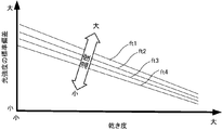
- the correlation storage unit 201b for example, as shown in FIG. 7, a plurality of light intensity variations ⁇ (standard deviation) corresponding to the magnitude of the pressure p of the wet steam and the dryness ⁇ of the wet steam are stored.
- the correlations fp1 to fp4 are stored as a data table.
- the correlations fp1 to fp4 exemplify the relationship between the amount of variation in light intensity and the dryness of the wet steam for each wet steam pressure for the wet steam assumed by the dryness measuring apparatus 1b.
- Equation (2) is described as an approximation of a linear function. Is possible.
- the dryness measuring unit 102b substitutes the amount of variation ⁇ of the light intensity corresponding to the pressure p of the wet steam into the equation (2), and calculates and outputs the dryness ⁇ . .
- the light transmitted through the wet steam is incident on the optical waveguide 22 on the opposite side of the pipe 20 and propagates, and is received by the light receiving unit 12.
- the light receiving unit 12 outputs a light reception signal Sd corresponding to the intensity of light transmitted through the wet steam.
- the pressure sensor 23 measures the pressure p of the wet steam flowing in the pipe 20 and outputs it to the computer apparatus 100 as a pressure signal Sp.
- the variation amount measuring unit 101 refers to the light reception signal Sd and calculates the variation amount (standard deviation) ⁇ from the predetermined sample interval and the light intensity of the number of samples. If the interval and / or the number of samples differs when a data table or a relational expression showing the correlation between the variation in the intensity of light referred to by the dryness measurement unit 102 and the dryness of wet steam is created. Performs a predetermined conversion calculation to calculate the variation amount ⁇ .
- the dryness measuring unit 102b refers to the correlation storage unit 201b using the measured wet steam pressure p and the calculated variation amount ⁇ as reference values, or a relational expression such as the above equation (2). To calculate the dryness ⁇ of the corresponding wet steam.
- the dryness ⁇ of the output wet steam is displayed on the output device 106, for example.
- the dryness ⁇ can be calculated based on the correlation between the light intensity variation ⁇ that is not influenced by the phase state of the wet steam and the dryness ⁇ of the wet steam. Even in the transient state, it is possible to reliably measure the dryness of the wet steam.
- the correlation between the light intensity variation ⁇ and the wet steam dryness ⁇ prepared corresponding to the wet steam pressure p is used. Accurate wet steam dryness can be measured even under conditions that affect
- the third embodiment relates to a dryness measuring apparatus in the case where the temperature of the wet steam is taken into consideration.
- the dryness measuring apparatus 1c in this Embodiment 3 is an apparatus that measures dryness based on a variation amount of light intensity of wet steam corresponding to the temperature of the wet steam to be measured.
- the storage device 200 includes a light emitting unit 11, a light receiving unit 12, a variation measuring unit 101, a dryness measuring unit 102c, and a correlation storage unit 201c.
- a temperature sensor 24 is further provided.
- the temperature sensor 24 is disposed on the pipe 20, measures the temperature t of the wet steam inside the pipe 20, and outputs it as a temperature signal St to the computer apparatus 100.
- the light emitting unit 11, the light receiving unit 12, and the correlation storage unit 201c are optional configurations, and the variation amount measuring unit 101 and the dryness measuring unit 102c execute a predetermined software program by the computer apparatus 100.
- This is the same as the first embodiment in that it is a functional block realized functionally.
- the correlation storage unit 201c of the storage device 200 has a correlation indicating a correlation between the light intensity variation ⁇ (standard deviation) corresponding to the wet steam temperature t and the wet steam dryness ⁇ .
- the relationship table is stored, and the dryness measurement unit 102c dries the wet steam based on the correlation between the amount of variation in light intensity corresponding to the temperature of the wet vapor and the dryness stored in the correlation storage unit 201c.
- This is different from the first embodiment in that the degree ⁇ is measured. Since other configurations are the same as those in the first embodiment, description thereof is omitted.
- the dryness measurement unit 102c uses the temperature signal St indicating the temperature t of the wet steam detected by the temperature sensor 24 and the variation amount ⁇ measured by the variation amount measurement unit 101 as a reference value. , The dryness ⁇ corresponding to the variation value ⁇ (standard deviation) is acquired from the correlation corresponding to the temperature t, and output as an output value.
- the correlation storage unit 201c for example, as shown in FIG. 9, a plurality of light intensity variations ⁇ (standard deviation) and wet steam dryness ⁇ corresponding to the magnitude of the temperature t of the wet steam are stored.
- the correlations ft1 to ft4 are stored as a data table.
- the correlations ft1 to ft4 indicate the relationship between the amount of variation in light intensity and the dryness of the wet steam for each wet steam temperature, with respect to the wet steam assumed by the dryness measuring apparatus 1.
- Equation (3) is described as an approximate expression of a linear function. It is possible.
- the dryness measuring unit 102c substitutes the amount of variation ⁇ of the light intensity corresponding to the temperature t of the wet steam into the equation (3), and calculates and outputs the dryness ⁇ . .
- the light transmitted through the wet steam is incident on the optical waveguide 22 on the opposite side of the pipe 20 and propagates, and is received by the light receiving unit 12.
- the light receiving unit 12 outputs a light reception signal Sd corresponding to the intensity of light transmitted through the wet steam.
- the temperature sensor 24 measures the temperature t of the wet steam flowing in the pipe 20 and outputs it to the computer apparatus 100 as a temperature signal St.
- the variation amount measuring unit 101 refers to the light reception signal Sd and calculates the variation amount (standard deviation) ⁇ from the predetermined sample interval and the light intensity of the number of samples. If the interval and / or the number of samples differs when a data table or a relational expression showing the correlation between the variation in the intensity of light referred to by the dryness measurement unit 102 and the dryness of wet steam is created. Performs a predetermined conversion calculation to calculate the variation amount ⁇ .
- the dryness measurement unit 102c refers to the correlation storage unit 201c using the measured wet steam temperature t and the calculated variation amount ⁇ as reference values, or a relational expression such as the above equation (3). To calculate the dryness ⁇ of the corresponding wet steam.
- the dryness ⁇ of the output wet steam is displayed on the output device 106, for example.
- the dryness ⁇ can be calculated based on the correlation between the light intensity variation ⁇ that is not affected by the wet steam phase state and the wet steam dryness ⁇ . Even in the transient state, it is possible to reliably measure the dryness of the wet steam.
- the temperature of the wet steam is the dryness degree. Accurate wet steam dryness can be measured even under conditions that affect
- the dryness of the wet steam is measured based on the variation amount of the light intensity.
- the dryness of the wet steam is measured based on the variation amount of the absorbance.
- the present invention relates to a dryness measuring apparatus for measuring.
- the dryness measuring device 1d is a device that measures dryness based on the amount of variation in the absorbance of wet steam.
- the light emitting unit 11, the spectrophotometer 13, a variation amount measuring unit 101b, a dryness measuring unit 102d, and a storage device 200 are examples of the light emitting unit 11, the spectrophotometer 13, a variation amount measuring unit 101b, a dryness measuring unit 102d, and a storage device 200.
- the fourth embodiment is different from the first embodiment in that a spectrophotometer 13 is provided instead of the light receiving unit 12 first.
- the spectrophotometer 13 is a measuring unit that measures the absorbance based on the intensity of light transmitted through the wet steam, and there is no limitation on the configuration thereof.
- the variation amount measuring unit 101b measures the variation amount ⁇ of absorbance
- the correlation storage unit 201d of the storage device 200 indicates the correlation between the variation amount ⁇ (standard deviation) of absorbance and the dryness ⁇ of wet steam.
- a correlation table is stored, and the dryness measuring unit 102d measures the dryness ⁇ of wet steam based on the correlation between the amount of variation in absorbance and the dryness stored in the correlation storage unit 201d. Different from the first embodiment.
- the variation amount measuring unit 101b and the dryness measuring unit 102d are functional blocks that are functionally realized by the computer device 100 executing a predetermined software program. Same as 1.
- the spectrophotometer 13 calculates the absorbance based on the intensity of light that passes through the wet steam, and outputs it as an absorbance signal Sa.
- the absorbance A is defined as in Expression (4), where I 0 is the incident light intensity and I is the intensity of the received light.
- Absorbance A ⁇ log 10 (I / I 0 ) (4) From the above, if the intensity of light passing through the wet steam can be measured, the absorbance A is uniquely specified. Therefore, the computer apparatus 100 may be configured to input the received light signal Sd including the light intensity as in the first to third embodiments and calculate the absorbance A based on the equation (4).
- the variation measuring unit 101b receives the absorbance signal Sa from the spectrophotometer 13, samples the absorbance indicated by the absorbance signal Sa for a predetermined number of samples at a predetermined interval, for example, 100 samples at an interval of 300 msec, and samples the sample.
- the standard deviation of the absorbance for several minutes is calculated as the absorbance variation ⁇ .
- the dryness measurement unit 102d refers to the correlation storage unit 201d of the storage device 200 using the absorbance variation amount ⁇ measured by the variation amount measurement unit 101b as a reference value, and determines the correlation between the absorbance variation amount and the dryness.
- the dryness ⁇ corresponding to the absorbance variation value ⁇ (standard deviation) is acquired and output as an output value.
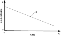
- a plurality of correlations f3 between the absorbance variation amount ⁇ (standard deviation) and the wet steam dryness ⁇ as shown in FIG. 11 are stored as a data table.
- the light transmitted through the wet steam is incident on the optical waveguide 22 on the opposite side of the pipe 20 and propagates, and is received by the spectrophotometer 13.
- the spectrophotometer 13 outputs an absorbance signal Sa indicating the absorbance corresponding to the intensity of light transmitted through the wet steam.
- the variation amount measuring unit 101b refers to the absorbance signal Sa and calculates the variation amount (standard deviation) ⁇ from the absorbance of the sample interval and the number of samples defined in advance. If the sample interval and / or the number of samples when the data table or the relational expression showing the correlation between the amount of variation in absorbance referred to by the dryness measurement unit 102d and the dryness of wet steam is different, and / or the number of samples is different, The variation amount ⁇ is calculated by performing a predetermined conversion calculation.
- the dryness measurement unit 102d refers to the correlation storage unit 201d using the calculated variation amount ⁇ of absorbance as a reference value, or calculates based on the relational expression such as the above equation (5), and varies the absorbance. Outputs the dryness ⁇ of wet steam corresponding to the amount.
- the dryness ⁇ of the output wet steam is displayed on the output device 106, for example.
- the dryness ⁇ can be calculated based on the correlation between the absorbance variation amount ⁇ that is not affected by the phase state of the wet steam and the dryness ⁇ of the wet steam. Even in the state, it is possible to reliably measure the dryness of the wet steam.
- the present invention is not limited to the above-described embodiment, and can be variously modified and applied.
- the wet steam is dried based on the variation amount of the absorbance and the pressure p or / and the temperature t of the wet steam.
- the dryness of wet steam can be measured, it can be applied to a system or a plant that performs control based on the dryness in a transient state.
- the present invention can be applied to heavy and large industrial fields.
- the dryness of the wet steam at the steam turbine outlet depends on the power generation efficiency, so the dryness at the turbine outlet is measured in real time (steam turbine wet loss measurement) without waiting for the steam to stabilize.
- steam turbine wet loss measurement steam turbine wet loss measurement
Landscapes
- Physics & Mathematics (AREA)
- Spectroscopy & Molecular Physics (AREA)
- Health & Medical Sciences (AREA)
- Life Sciences & Earth Sciences (AREA)
- Chemical & Material Sciences (AREA)
- Analytical Chemistry (AREA)
- Biochemistry (AREA)
- General Health & Medical Sciences (AREA)
- General Physics & Mathematics (AREA)
- Immunology (AREA)
- Pathology (AREA)
- Investigating Or Analysing Materials By Optical Means (AREA)
Abstract
湿り蒸気が過渡状態である場合でも乾き度を測定することを課題とする。測定対象の湿り蒸気を透過した光の強度または吸光度のばらつき量を測定するばらつき量測定部(101)と、光の強度または吸光度のばらつき量と乾き度との相関関係に基づいて湿り蒸気の乾き度を測定する乾き度測定部(102)とを備える。湿り蒸気が過渡状態であったとしても湿り蒸気の乾き度を測定可能である。
Description
本発明は湿り蒸気の測定技術に係り、乾き度測定装置及び乾き度測定方法に関する。
水は沸点に達した後、水蒸気ガス(気相部分:飽和蒸気)と、水滴(液相部分:飽和水)と、が混合した湿り蒸気となる。ここで、湿り蒸気に対する水蒸気ガスの重量比を、「乾き度」という。例えば、水蒸気ガスと、水滴と、が半分ずつ存在すれば、乾き度は0.5となる。また、水滴が存在せず、水蒸気ガスのみが存在する場合は、乾き度は1.0となる。熱交換器等において、湿り蒸気が保有する顕熱と、潜熱と、を有効に利用することや、水蒸気タービンにおいて、タービン翼の腐食を防止すること、等の観点から、湿り蒸気の乾き度を1.0に近い状態にすることが望まれている。そのため、乾き度を測定する様々な方法が提案されている。
例えば、特許文献1は、配管に設けられた圧力調節弁の前後で全エンタルピーに変化がないことを利用して、圧力調節弁の前後の湿り蒸気流量及び圧力に基づき、飽和蒸気表を用いて飽和水エンタルピーと飽和蒸気エンタルピーとを求めて、乾き度を算出する技術を開示している。
しかし、特許文献1に開示された技術は、湿り蒸気の流量及び圧力を検出するセンサの時定数が長く、また、測定対象の湿り蒸気を二相状態から気相状態に状態変化させ、さらに測定対象を気相状態で安定化させる必要があるため、乾き度の測定に時間がかかるという問題があった。このため、湿り状態が定常状態にあるときの乾き度を測定することは可能であったが、湿り蒸気が安定するまでの過渡状態にあるときの乾き度測定には適さなかった。
そこで、本発明は、湿り蒸気が過渡状態である場合でも乾き度を測定することを目的の1つとする。
なお、前記目的に限らず、後述する実施形態に示す解決原理を有する解決手段を得ることも本発明の他の目的の一つとして位置付けることができる。
本願発明者は、湿り蒸気が安定していない過渡状態において乾き度を測定する技術を鋭意研究したところ、湿り蒸気を透過した光の強度または吸光度のばらつきと湿り蒸気の乾き度とが強い相関関係を有するという知見を得て、この相関関係を利用した乾き度の測定技術を発明するに至った。具体的には、上記課題を解決するために、本発明は以下の構成要件を備えるものである。
(1-1)本発明の乾き度測定装置は、測定対象の湿り蒸気を透過した光の強度または吸光度のばらつき量を測定するばらつき量測定部と、前記光の強度または吸光度のばらつき量と乾き度との相関関係に基づいて前記湿り蒸気の乾き度を測定する乾き度測定部と、を備えている。
(1-2)また本発明の乾き度測定方法は、湿り蒸気に光を照射することと、前記湿り蒸気を透過した光を受光することと、前記光の強度または吸光度のばらつき量と乾き度との相関関係に基づいて前記湿り蒸気の乾き度を測定することと、を含む。
本発明は、所望により、以下の構成を備えていてもよい。
(2)上記発明において、前記湿り蒸気の圧力を計測する圧力計測部を備え、前記相関関係は、前記湿り蒸気の圧力に対応した前記光の強度または吸光度のばらつき量と乾き度との相関関係であり、前記乾き度測定部は、計測された前記湿り蒸気の圧力に対応する前記相関関係に基づいて前記湿り蒸気の乾き度を測定する。
(2)上記発明において、前記湿り蒸気の圧力を計測する圧力計測部を備え、前記相関関係は、前記湿り蒸気の圧力に対応した前記光の強度または吸光度のばらつき量と乾き度との相関関係であり、前記乾き度測定部は、計測された前記湿り蒸気の圧力に対応する前記相関関係に基づいて前記湿り蒸気の乾き度を測定する。
(3)上記発明において、前記湿り蒸気の温度を計測する温度計測部を備え、前記相関関係は、前記湿り蒸気の温度に対応した前記光の強度または前記吸光度のばらつき量と乾き度との相関関係であり、前記乾き度測定部は、計測された前記湿り蒸気の温度に対応する前記相関関係に基づいて前記湿り蒸気の乾き度を測定する。
(4)上記発明において、前記測定対象の湿り蒸気に光を照射する発光部と、前記湿り蒸気を透過した光を受光する受光部と、受光した前記光の強度を計測する光強度計測部と、前記光の強度または前記吸光度のばらつき量と乾き度との相関関係を記憶する相関関係記憶部と、をさらに備え、前記ばらつき量測定部は、前記光の強度または前記吸光度のばらつき量を測定し、前記乾き度測定部は、測定された前記光の強度または前記吸光度のばらつき量を参照値として前記相関関係記憶部に格納された前記相関関係を参照し、前記湿り蒸気の乾き度を測定する。
本発明によれば、光の強度または吸光度のばらつき量と乾き度の相関関係に基づき、湿り蒸気が過渡状態であったとしても湿り蒸気の乾き度を測定可能である。
以下、図面を参照して本発明の実施の形態を説明する。ただし、以下に説明する実施形態は、あくまでも例示であり、以下に明示しない種々の変形や技術の適用を排除する意図はない。即ち、本発明は、その趣旨を逸脱しない範囲で種々変形(各実施例を組み合わせる等)して実施することができる。また、以下の図面の記載において、同一又は類似の部分には同一又は類似の符号を付して表している。図面は模式的なものであり、必ずしも実際の寸法や比率等とは一致しない。図面相互間においても互いの寸法の関係や比率が異なる部分が含まれていることがある。
(定義)
本明細書で使用する主たる用語を以下のとおりに定義する。
「蒸気」:各実施形態では、水蒸気のことを意味するが、気相部分と液相部分との二相状態となる物質の蒸気であればよく、水蒸気に限定されない。
「乾き度」:蒸気中の気相部分と液相部分との重量割合のことをいう。乾き度[%]=100[%]-湿り度[%]の関係がある。
「湿り蒸気」:乾き度χが0-100[%]の蒸気をいう。
「飽和蒸気」:湿り蒸気の気相部分をいう。乾き飽和蒸気(飽和乾き蒸気)ともいう。
「飽和水」:湿り蒸気の液相部分をいう。
「光の強度」(光強度):光(電磁波)の強さを表す物理量をいい、その称呼や単位に限定はない。例えば、放射強度、光度、光量子束密度など、それぞれ単位が異なるが相互に換算可能な物理量である。
本明細書で使用する主たる用語を以下のとおりに定義する。
「蒸気」:各実施形態では、水蒸気のことを意味するが、気相部分と液相部分との二相状態となる物質の蒸気であればよく、水蒸気に限定されない。
「乾き度」:蒸気中の気相部分と液相部分との重量割合のことをいう。乾き度[%]=100[%]-湿り度[%]の関係がある。
「湿り蒸気」:乾き度χが0-100[%]の蒸気をいう。
「飽和蒸気」:湿り蒸気の気相部分をいう。乾き飽和蒸気(飽和乾き蒸気)ともいう。
「飽和水」:湿り蒸気の液相部分をいう。
「光の強度」(光強度):光(電磁波)の強さを表す物理量をいい、その称呼や単位に限定はない。例えば、放射強度、光度、光量子束密度など、それぞれ単位が異なるが相互に換算可能な物理量である。
「吸光度」:光が湿り蒸気中を通過した際に光の強度がどの程度弱まるかを示す無次元量であり、光学密度ともいう。吸光度といっても光の吸収のみならず、散乱や反射により光の強度が弱まる場合も含む。
「ばらつき量」:母集団となる光の強度または吸光度の測定値の差異を定量化した値であり限定はないが、本実施形態では、母集団の分散の平方根で表される「標準偏差」で表すものとする。
(原理説明)
まず本発明の原理を、図2-図5を参照しながら説明する。
上述したように、本願発明者は、湿り蒸気が安定していない過渡状態において乾き度を測定する技術を鋭意研究し、湿り蒸気を透過した光の強度または吸光度のばらつきと湿り蒸気の乾き度とが強い相関関係を有するという知見を得るに至った。
まず本発明の原理を、図2-図5を参照しながら説明する。
上述したように、本願発明者は、湿り蒸気が安定していない過渡状態において乾き度を測定する技術を鋭意研究し、湿り蒸気を透過した光の強度または吸光度のばらつきと湿り蒸気の乾き度とが強い相関関係を有するという知見を得るに至った。
湿り蒸気がパイプ(配管)を流れると、湿り蒸気の液相部分(飽和水)と気相部分(飽和蒸気)とが湿り蒸気の流速に応じてパイプ内で偏在するようになる。このようなパイプの側壁に光の透過路を設け、湿り蒸気の流通方向に交差する横方向から光を透過させ、湿り蒸気を透過する光の強度を測定したところ、光の強度のばらつき量がパイプ内部の湿り蒸気の乾き度と強い相関関係を有することを発見するに至った。
図2は、時間に応じて変化する、湿り蒸気を透過する光の強度の標準偏差と、それに対応する湿り蒸気の乾き度を示すとの相関関係を示す図である。図2において、特性f1は、標準偏差である。当該標準偏差は、所定の単位期間、例えば約300msecごとに連続100サンプルを取得して、合計約30秒間の期間を1単位として標準偏差を計算し、湿り蒸気を透過した光の強度のばらつき量としてプロットしたものである。図2に示されるように、光の強度のばらつき量(標準偏差)は、パイプ内部の湿り蒸気の状態に依存して刻一刻と変動する。一方、図2の特性f2は、同じ時間軸について、パイプ内部の湿り蒸気の乾き度を測定してプロットしたものである。
光の強度のばらつき量に係る特性f1と湿り蒸気の乾き度に係る特性f2とを比べると、光の強度のばらつき量が多い(標準偏差が大きい)ほど、湿り蒸気の乾き度が小さく、光の強度のばらつき量が少ない(標準偏差が小さい)ほど、湿り蒸気の乾き度が大きくなることが判る。また光の強度のばらつき量の変化に対応する湿り蒸気の乾き度の変化は、対応しているように見える。
そこで、湿り蒸気の乾き度と光の強度のばらつき量との関係を調べるために、これら2つのパラメータを直交軸にプロットすると、図3に示されるような関係があることが判った。
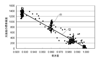
図3は、湿り蒸気の乾き度と光の強度の標準偏差との相関関係を示す図である。図3では、乾き度に対する光強度のばらつき量(標準偏差)に係る特性f1が点の集合で示され、この光強度のばらつき量に係る特性f1を直線近似した特性f2が直線で示されている。図3に示すように、湿り蒸気の乾き度が下がると光の強度のばらつき量(標準偏差)が大きくなり、湿り蒸気の乾き度が上がると光の強度のばらつき量が小さくなるという関係にあることが示されており、湿り蒸気の乾き度は、湿り蒸気を透過した光の強度のばらつき量と線形的な一次相関関係があることが判明した。
なお、図3では、湿り蒸気の乾き度と光の強度のばらつき量との間に一次相関関係があることが示されているが、これに限らない。湿り蒸気の状態や光の検出方法等の測定条件によって、一次相関とは異なる相関関係を有することも考えられる。本発明は、湿り蒸気の乾き度と光の強度のばらつき量との関係が、実験等で確認可能な一定の相関関係(例えば、多次相関、指数対数的相関等)を有していれば、適用することが可能である。
この現象は、湿り蒸気の乾き度が上昇し、湿り蒸気のうち液相部分(飽和水)の量が増えると光の強度のばらつき量が増え、湿り蒸気の乾き度が下降し、湿り蒸気のうち液相部分の量が減少すると光の強度のばらつき量が減るということであり、図4および図5のようなモデルから理解することができる。
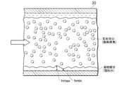
図4は湿り蒸気の液相部分が比較的多い場合のパイプ(管路)断面の模式図であり、図5は湿り蒸気の液相部分が比較的少ない場合のパイプ(管路)断面の模式図である。図4および図5に示すように、湿り蒸気がある程度の速さで流れている場合、湿り蒸気のうちの液相部分(飽和水)は、パイプ20の内壁に沿って流れ、パイプ20の軸芯近くに集まって流れるようになる。
ここで、図4に示すように、湿り蒸気の液相部分が比較的多くなると、すなわち湿り蒸気の乾き度が低くなると、パイプ20の内壁面に形成される液相部分の厚み(内壁面から見た高さ)が大きくなる。液相部分の厚みが大きくなると、図4に示されるように、液相部分の表面が相対的に大きく波打つようになって、液相部分の高さの最大値hmaxと最小値hminとの差も大きくなる。このような状態の湿り蒸気にパイプ20の直径方向から光を照射した場合、湿り蒸気を透過する光の強度は、液相部分の高さに対応して変化するため、液相部分の高さの最大値hmaxと最小値hminとの差が大きいと、それに連れて光の強度のばらつき量も大きくなると考えられる。
一方、図5に示すように、湿り蒸気の液相部分が比較的少なくなると、すなわち湿り蒸気の乾き度が高くなると、パイプ20の内壁面に形成される液相部分の厚みが小さくなる。液相部分の厚みが小さくなると、図5に示されるように、液相部分の表面に生ずる波が小さくなって、液相部分の高さの最大値hmaxと最小値hminとの差が小さくなる。このような状態の湿り蒸気をパイプ20の直径方向から透過する光の強度は、比較的小さな液相部分の高さの最大値hmaxと最小値hminとの差に対応したものとなり、光の強度のばらつき量が小さくなると考えられる。
なお、図4および図5で示した断面図は、現象を理解するための簡略したモデルにすぎず、これらの図に限定されるものではない。パイプを流れる湿り蒸気の相状態はその流速や乾き度、温度や圧力によって種々に変化するものである。湿り蒸気の相状態がどのように変動しても、湿り蒸気の乾き度と光の強度のばらつき量との間に相関関係があるものと理解すべきである。
また、湿り蒸気の相状態は、一般に、湿り蒸気の圧力に影響を受けるものであるため、湿り蒸気の圧力に応じて、光の強度のばらつき量と湿り蒸気の乾き度との相関関係も影響を受けると考えられる。
さらに、湿り蒸気の相状態は、一般に、湿り蒸気の温度にも影響を受けるものであるため、湿り蒸気の温度に応じて、光の強度のばらつき量と湿り蒸気の乾き度との相関関係も影響を受けると考えられる。
さらにまた、上記説明では、湿り蒸気を透過した光の強度と湿り蒸気の乾き度との関係に言及したが、湿り蒸気により光は吸収、反射、散乱させられるため、光の強度が変化するのに対応して、吸光度も変化する。よって、吸光度のばらつき量と湿り蒸気の乾き度との間にも、上記同様の相関関係があるものと考えるべきである。
以下、上記原理に鑑み本願発明者が鋭意考案した本発明の実施形態を説明する。実施形態1では、湿り蒸気の圧力および温度の影響を考慮しなくてよい状況における光の強度のばらつき量に基づく乾き度測定装置を説明する。実施形態2では、湿り蒸気の圧力を考慮する場合における乾き度測定装置を説明する。実施形態3では、湿り蒸気の温度を考慮する場合における乾き度測定装置を説明する。実施形態4では、吸光度のばらつき量に基づく乾き度測定装置を説明する。
(実施形態1)
本実施形態1は、湿り蒸気を透過した光の強度のばらつきと乾き度との相関関係に基づいて乾き度を測定する乾き度測定装置に関する。特に本実施形態1は、湿り蒸気の圧力および温度の影響を考慮しなくてよい場合、例えば、湿り蒸気の圧力および温度とも、光の強度のばらつき量に大きな影響を与えないような条件で実施される乾き度測定について説明する。
本実施形態1は、湿り蒸気を透過した光の強度のばらつきと乾き度との相関関係に基づいて乾き度を測定する乾き度測定装置に関する。特に本実施形態1は、湿り蒸気の圧力および温度の影響を考慮しなくてよい場合、例えば、湿り蒸気の圧力および温度とも、光の強度のばらつき量に大きな影響を与えないような条件で実施される乾き度測定について説明する。
(構成)
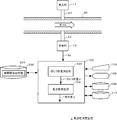
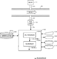
図1に、本実施形態1における乾き度測定装置1の構成を示す。図1に示すように、実施形態1に係る乾き度測定装置1は、測定対象の湿り蒸気を透過した光の強度に基づいて湿り蒸気の乾き度を測定する装置であり、例示的に、発光部11、受光部12、ばらつき量測定部101、乾き度測定部102、および記憶装置200を備えて構成される。
図1に、本実施形態1における乾き度測定装置1の構成を示す。図1に示すように、実施形態1に係る乾き度測定装置1は、測定対象の湿り蒸気を透過した光の強度に基づいて湿り蒸気の乾き度を測定する装置であり、例示的に、発光部11、受光部12、ばらつき量測定部101、乾き度測定部102、および記憶装置200を備えて構成される。
上記の構成のうち、発光部11および受光部12については、湿り蒸気を透過する光の強度に対応する物理量を出力可能であれば、任意の構成が適用可能であるため、オプショナルな構成である。
また、上記した構成要素のうち、ばらつき量測定部101および乾き度測定部102は、所定のソフトウェアプログラムをコンピュータ装置100が実行することにより機能的に実現される機能ブロックである。コンピュータ装置100は、例示として、入力装置104、出力装置106、プログラム記憶装置108、一時記憶装置110、および記憶装置200を備える。
入力装置104は、オペレータが所定の指示を操作する入力手段である。入力装置104の一例としては、スイッチ及びキーボード等が使用可能である。出力装置106は、オペレータに対しコンピュータ装置100の処理結果を示す出力手段である。出力装置106の一例としては、光インジケータ、デジタルインジケータ、及び液晶表示装置等が使用可能である。出力装置106は、例えば、乾き度測定部102が算出したパイプ20内部の湿り蒸気の乾き度χ等を表示する。プログラム記憶装置108は、コンピュータ装置100を上記機能ブロックとして機能させるためのソフトウェアプログラムを格納するメモリである。一時記憶装置110は、コンピュータ装置100がソフトウェアプログラムを実行するに際に一時的にデータを記憶するメモリである。
記憶装置200は、コンピュータ装置100から参照可能に接続されているメモリであり、相関関係記憶部201を備える。相関係記憶部201は、乾き度測定部102が演算処理を実行するにあたり必要な、光の強度のばらつき量σ(標準偏差)と湿り蒸気の乾き度χとの相関関係を示す相関関係テーブルを格納する記憶領域である。相関関係記憶部201は、後述する関係式で代替可能であり、よってオプショナルな構成であるといえる。
発光部11は、所定の波長の光を射出する発光手段である。例えば、発光部11としては、発光ダイオード、スーパールミネッセントダイオード、半導体レーザ、レーザ発振器、蛍光放電管、低圧水銀灯、キセノンランプ、及び電球等が使用可能である。
発光部11には、光導波路21を接続してもよい。光導波路21は、パイプ20の側壁を貫通して設けられたり、パイプ20の側壁に設けられた光透過性の窓に接続されたりする。例えば、光導波路21により伝搬された光は、光導波路21の端部からパイプ20の内部に進入する。光導波路21には、ポリメタクリル酸メチル樹脂(PMMA:Poly(methyl methacrylate))からなるプラスチック光ファイバ、及び石英ガラスからなるガラス光ファイバ等が使用可能であるが、発光部11が発した光を伝搬可能であれば、これに限定されない。
パイプ20は、測定対象となる湿り蒸気が流通する配管である。パイプ20には、上記した光導波路21から照射され、パイプ20の内部の湿り蒸気を通過した光が進入する光導波路22を接続してもよい。光導波路22は、パイプ20の側壁を貫通して設けられたり、パイプ20の側壁に設けられた光透過性の窓に接続されたりする。光導波路22の端部は、パイプ20の径方向で光導波路21の端部と対向している。光導波路22は、パイプ20の内部の湿り蒸気を透過した光を受光部12に導くことが可能に構成されている。
受光部12は、パイプ20内の湿り蒸気を透過した光を受ける受光手段である。例えば、受光部12としては、には、フォトダイオード、フォトトランジスタ等の光電変換素子を使用可能である。受光部12は、湿り蒸気を透過した光の強度に応じた受光信号Sdを出力する。
なお、パイプ20の側壁に光導波路21を設けずに発光部11を接近させて設けてもよく、パイプ20の側壁に光導波路22を設けずに受光部12を接近させて設けてもよい。また図1では、発光部11と受光部12とが対向して設けられているが、この代わりに、発光部と受光部との双方が一体化された発光受光素子を用いてもよい。発光受光素子を用いる場合、発光受光素子と対向するパイプの側壁に反射板を配置してもよい。発光受光素子から発せられた光は、パイプ内部を進行し、反射板で反射され、再びパイプ内を進行して発光受光素子に受光される。さらに、発光部11および受光部12に代えて、公知の分光計など、光の強度に対応する出力が得られる分光計等の光学的計測機器を適用することも可能である。
ばらつき量測定部101は、測定対象の湿り蒸気を透過した光の強度のばらつき量を測定する測定手段である。具体的には、ばらつき量測定部101は、受光部12から受光信号Sdを入力し、所定の間隔で所定のサンプル数だけ、例えば、300msec間隔で100サンプルだけ、受光信号Sdが示す光の強度をサンプリングし、そのサンプル数分の光の強度の標準偏差を、光の強度のばらつき量σとして算出する。このサンプリング間隔およびサンプル数は、乾き度測定部102が参照する光の強度のばらつき量と乾き度との相関関係の測定時と同じか、または、対応関係にある必要がある。
乾き度測定部102は、記憶装置200の相関関係記憶部201に記憶された光の強度のばらつき量と乾き度との相関関係に基づいて湿り蒸気の乾き度χを測定する測定手段である。具体的には、乾き度測定部102は、ばらつき量測定部101が測定したばらつき量σを参照値として、記憶装置20の相関関係記憶部201を参照し、ばらつき値σ(標準偏差)に対応する乾き度χを取得し、出力値として出力する。
相関関係記憶部201には、例えば、図3に示すような、光の強度のばらつき量σ(標準偏差)と湿り蒸気の乾き度χとの相関関係がデータテーブルとして格納される。この相関関係は、当該乾き度測定装置1が想定している湿り蒸気について、予め規定された圧力と温度における、光強度のばらつき量と湿り蒸気の乾き度との関係を示すものである。
なお、光の強度のばらつき量σ(標準偏差)と湿り蒸気の乾き度χとの相関関係は、ある一定の相関関係を有するため、当該関係を以下の式(1)のような関係式として記述することもできる。光の強度のばらつき量σと湿り蒸気の乾き度χとの相関関係が、図3に示したような一次相関関係であれば、式(1)は一次関数の近似式として記述することが可能である。
乾き度χ=f(σ) …(1)
したがって、関係式を用いる場合には、乾き度測定部102は、光の強度のばらつき量σを式(1)に代入し、乾き度χを演算して出力する。
乾き度χ=f(σ) …(1)
したがって、関係式を用いる場合には、乾き度測定部102は、光の強度のばらつき量σを式(1)に代入し、乾き度χを演算して出力する。
(動作)
次に本実施形態1の動作を説明する。
まず、湿り蒸気がパイプ20の内部を流れている状態で湿り蒸気の乾き度を測定する場合、発光部11に光を発光させる。発光部11から光導波路21を伝播した光は、パイプ20内部の湿り蒸気に照射される。
次に本実施形態1の動作を説明する。
まず、湿り蒸気がパイプ20の内部を流れている状態で湿り蒸気の乾き度を測定する場合、発光部11に光を発光させる。発光部11から光導波路21を伝播した光は、パイプ20内部の湿り蒸気に照射される。
湿り蒸気を透過した光は、パイプ20の反対側にある光導波路22に入射して伝播し、受光部12にて受光される。受光部12は、湿り蒸気を透過した光の強度に対応した受光信号Sdを出力する。
ばらつき量測定部101は、受光信号Sdを参照して、予め規定されたサンプルの間隔およびサンプル数の光の強度からばらつき量(標準偏差)σを演算する。もしも、乾き度測定部102が参照する光の強度のばらつき量と湿り蒸気の乾き度との相関関係を示すデータテーブルまたは関係式を作成した時のサンプルの間隔および/またはサンプル数が異なる場合には、所定の変換演算をしてばらつき量σを演算する。
次いで、乾き度測定部102は、演算されたばらつき量σを参照値として記憶装置200の相関関係記憶部201を参照するか、上記式(1)のような関係式に基づく演算をして、対応する湿り蒸気の乾き度χを出力する。出力された湿り蒸気の乾き度χは、例えば、出力装置106に表示される。
(効果)
以上説明した実施形態1によれば、湿り蒸気の相状態に影響を受けない光の強度のばらつき量σと湿り蒸気の乾き度χとの相関関係に基づき乾き度χを演算可能なので、湿り蒸気が過渡状態であったとしても湿り蒸気の乾き度を確実に測定することが可能である。
以上説明した実施形態1によれば、湿り蒸気の相状態に影響を受けない光の強度のばらつき量σと湿り蒸気の乾き度χとの相関関係に基づき乾き度χを演算可能なので、湿り蒸気が過渡状態であったとしても湿り蒸気の乾き度を確実に測定することが可能である。
(実施形態2)
上記実施形態1は、湿り蒸気の圧力および温度の影響を考慮しなくてよい場合における乾き度測定装置を説明したが、本実施形態2では、湿り蒸気の圧力を考慮する場合における乾き度測定装置に関する。
上記実施形態1は、湿り蒸気の圧力および温度の影響を考慮しなくてよい場合における乾き度測定装置を説明したが、本実施形態2では、湿り蒸気の圧力を考慮する場合における乾き度測定装置に関する。
(構成)
図6に、本実施形態2における乾き度測定装置1bの構成を示す。図6に示すように、実施形態2に係る乾き度測定装置1bは、測定対象の湿り蒸気の圧力に対応した、湿り蒸気の光の強度のばらつき量に基づいて乾き度を測定する装置であり、例示的に、発光部11、受光部12、ばらつき量測定部101、乾き度測定部102b、および相関関係記憶部201bを含む記憶装置200を備えて構成される。
図6に、本実施形態2における乾き度測定装置1bの構成を示す。図6に示すように、実施形態2に係る乾き度測定装置1bは、測定対象の湿り蒸気の圧力に対応した、湿り蒸気の光の強度のばらつき量に基づいて乾き度を測定する装置であり、例示的に、発光部11、受光部12、ばらつき量測定部101、乾き度測定部102b、および相関関係記憶部201bを含む記憶装置200を備えて構成される。
本実施形態2では、さらに圧力センサ23を備えている。圧力センサ23は、パイプ20に配置されており、パイプ20内部の湿り蒸気の圧力pを計測して圧力信号Spとしてコンピュータ装置100に出力する。
上記の構成のうち、発光部11、受光部12、および相関関係記憶部201bがオプショナルな構成であり、ばらつき量測定部101および乾き度測定部102bが、所定のソフトウェアプログラムをコンピュータ装置100が実行することにより機能的に実現される機能ブロックである点は、上記実施形態1と同じである。
本実施形態2では、記憶装置200の相関関係記憶部201bが、湿り蒸気の圧力pに対応した光の強度のばらつき量σ(標準偏差)と湿り蒸気の乾き度χとの相関関係を示す相関関係テーブルを格納し、乾き度測定部102bが、相関関係記憶部201bに記憶された、湿り蒸気の圧力に対応した光の強度のばらつき量と乾き度との相関関係に基づいて湿り蒸気の乾き度χを測定する点で、上記実施形態1と異なる。その他の構成については、上記実施形態1と同様であるため、説明を省略する。
具体的には、乾き度測定部102bは、圧力センサ23が検出した湿り蒸気の圧力pを示す圧力信号Sp、および、ばらつき量測定部101が測定したばらつき量σを参照値として、記憶装置200の相関関係記憶部201bを参照し、当該圧力pに対応した相関関係からばらつき値σ(標準偏差)に対応する乾き度χを取得し、出力値として出力する。
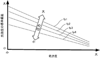
相関関係記憶部201bには、例えば、図7に示すような、湿り蒸気の圧力pの大きさに対応させた光の強度のばらつき量σ(標準偏差)と湿り蒸気の乾き度χとの複数の相関関係fp1~fp4がデータテーブルとして格納される。この相関関係fp1~fp4は、当該乾き度測定装置1bが想定している湿り蒸気について、湿り蒸気の圧力ごとに光強度のばらつき量と湿り蒸気の乾き度との関係を例示したものである。
なお、湿り蒸気の圧力pに対応した光の強度のばらつき量σ(標準偏差)と湿り蒸気の乾き度χとの相関関係は、ある一定の相関関係を有するため、当該関係を以下の式(2)のような関係式として記述することもできる。圧力pごとの光の強度のばらつき量σと湿り蒸気の乾き度χとの相関関係が、図7に示したような一次相関関係であれば、式(2)は一次関数の近似式として記述することが可能である。
乾き度χ=f(σ、p) …(2)
したがって、関係式を用いる場合には、乾き度測定部102bは、湿り蒸気の圧力pに対応した光の強度のばらつき量σを式(2)に代入し、乾き度χを演算して出力する。
乾き度χ=f(σ、p) …(2)
したがって、関係式を用いる場合には、乾き度測定部102bは、湿り蒸気の圧力pに対応した光の強度のばらつき量σを式(2)に代入し、乾き度χを演算して出力する。
(動作)
次に本実施形態2の動作を説明する。
まず、湿り蒸気がパイプ20の内部を流れている状態で湿り蒸気の乾き度を測定する場合、発光部11に光を発光させる。発光部11から光導波路21を伝播した光は、パイプ20内部の湿り蒸気に照射される。
次に本実施形態2の動作を説明する。
まず、湿り蒸気がパイプ20の内部を流れている状態で湿り蒸気の乾き度を測定する場合、発光部11に光を発光させる。発光部11から光導波路21を伝播した光は、パイプ20内部の湿り蒸気に照射される。
湿り蒸気を透過した光は、パイプ20の反対側にある光導波路22に入射して伝播し、受光部12にて受光される。受光部12は、湿り蒸気を透過した光の強度に対応した受光信号Sdを出力する。
また圧力センサ23は、パイプ20内を流れる湿り蒸気の圧力pを計測して圧力信号Spとしてコンピュータ装置100に出力する。
ばらつき量測定部101は、受光信号Sdを参照して、予め規定されたサンプルの間隔およびサンプル数の光の強度からばらつき量(標準偏差)σを演算する。もしも、乾き度測定部102が参照する光の強度のばらつき量と湿り蒸気の乾き度との相関関係を示すデータテーブルまたは関係式を作成した時のサンプルの間隔および/またはサンプル数が異なる場合には、所定の変換演算をしてばらつき量σを演算する。
次いで、乾き度測定部102bは、計測された湿り蒸気の圧力p、および、演算されたばらつき量σを参照値として相関関係記憶部201bを参照するか、上記式(2)のような関係式に基づいて演算し、対応する湿り蒸気の乾き度χを出力する。出力された湿り蒸気の乾き度χは、例えば、出力装置106に表示される。
(効果)
以上説明した実施形態2によれば、湿り蒸気の相状態に影響を受けない光の強度のばらつき量σと湿り蒸気の乾き度χとの相関関係に基づき乾き度χを演算可能なので、湿り蒸気が過渡状態であったとしても湿り蒸気の乾き度を確実に測定することが可能である。
以上説明した実施形態2によれば、湿り蒸気の相状態に影響を受けない光の強度のばらつき量σと湿り蒸気の乾き度χとの相関関係に基づき乾き度χを演算可能なので、湿り蒸気が過渡状態であったとしても湿り蒸気の乾き度を確実に測定することが可能である。
特に本実施形態2によれば、湿り蒸気の圧力pに対応して用意された光の強度のばらつき量σと湿り蒸気の乾き度χとの相関関係を用いるので、湿り蒸気の圧力が乾き度に影響を与えるような条件下でも正確な湿り蒸気の乾き度を測定可能である。
(実施形態3)
上記実施形態2では、湿り蒸気の圧力を考慮したが、本実施形態3では、湿り蒸気の温度を考慮する場合における乾き度測定装置に関する。
上記実施形態2では、湿り蒸気の圧力を考慮したが、本実施形態3では、湿り蒸気の温度を考慮する場合における乾き度測定装置に関する。
(構成)
図8に、本実施形態3における乾き度測定装置1cの構成を示す。図8に示すように、実施形態3に係る乾き度測定装置1cは、測定対象の湿り蒸気の温度に対応した、湿り蒸気の光の強度のばらつき量に基づいて乾き度を測定する装置であり、例示的に、発光部11、受光部12、ばらつき量測定部101、乾き度測定部102c、および相関関係記憶部201cを含む記憶装置200を備えて構成される。
図8に、本実施形態3における乾き度測定装置1cの構成を示す。図8に示すように、実施形態3に係る乾き度測定装置1cは、測定対象の湿り蒸気の温度に対応した、湿り蒸気の光の強度のばらつき量に基づいて乾き度を測定する装置であり、例示的に、発光部11、受光部12、ばらつき量測定部101、乾き度測定部102c、および相関関係記憶部201cを含む記憶装置200を備えて構成される。
本実施形態3では、さらに温度センサ24を備えている。温度センサ24は、パイプ20に配置されており、パイプ20内部の湿り蒸気の温度tを計測して温度信号Stとしてコンピュータ装置100に出力する。
上記の構成のうち、発光部11、受光部12、および相関関係記憶部201cがオプショナルな構成であり、ばらつき量測定部101および乾き度測定部102cが、所定のソフトウェアプログラムをコンピュータ装置100が実行することにより機能的に実現される機能ブロックである点は、上記実施形態1と同じである。
本実施形態3では、記憶装置200の相関関係記憶部201cが、湿り蒸気の温度tに対応した光の強度のばらつき量σ(標準偏差)と湿り蒸気の乾き度χとの相関関係を示す相関関係テーブルを格納し、乾き度測定部102cが、相関関係記憶部201cに記憶された、湿り蒸気の温度に対応した光の強度のばらつき量と乾き度との相関関係に基づいて湿り蒸気の乾き度χを測定する点で、上記実施形態1と異なる。その他の構成については、上記実施形態1と同様であるため、説明を省略する。
具体的には、乾き度測定部102cは、温度センサ24が検出した湿り蒸気の温度tを示す温度信号St、および、ばらつき量測定部101が測定したばらつき量σを参照値として、記憶装置200の相関関係記憶部201cを参照し、当該温度tに対応した相関関係からばらつき値σ(標準偏差)に対応する乾き度χを取得し、出力値として出力する。
相関関係記憶部201cには、例えば、図9に示すような、湿り蒸気の温度tの大きさに対応させた光の強度のばらつき量σ(標準偏差)と湿り蒸気の乾き度χとの複数の相関関係ft1~ft4がデータテーブルとして格納される。この相関関係ft1~ft4は、当該乾き度測定装置1が想定している湿り蒸気について、湿り蒸気の温度ごとに光強度のばらつき量と湿り蒸気の乾き度との関係を示すものである。
なお、湿り蒸気の温度tに対応した光の強度のばらつき量σ(標準偏差)と湿り蒸気の乾き度χとの相関関係は、ある一定の相関関係を有するため、当該関係を以下の式(3)のような関係式として記述することもできる。温度tごとの光の強度のばらつき量と湿り蒸気の乾き度χとの相関関係が、図9に示したような一次相関関係であれば、式(3)は一次関数の近似式として記述することが可能である。
乾き度χ=f(σ、t) …(3)
したがって、関係式を用いる場合には、乾き度測定部102cは、湿り蒸気の温度tに対応した光の強度のばらつき量σを式(3)に代入し、乾き度χを演算して出力する。
乾き度χ=f(σ、t) …(3)
したがって、関係式を用いる場合には、乾き度測定部102cは、湿り蒸気の温度tに対応した光の強度のばらつき量σを式(3)に代入し、乾き度χを演算して出力する。
(動作)
次に本実施形態3の動作を説明する。
まず、湿り蒸気がパイプ20の内部を流れている状態で湿り蒸気の乾き度を測定する場合、発光部11に光を発光させる。発光部11から光導波路21を伝播した光は、パイプ20内部の湿り蒸気に照射される。
次に本実施形態3の動作を説明する。
まず、湿り蒸気がパイプ20の内部を流れている状態で湿り蒸気の乾き度を測定する場合、発光部11に光を発光させる。発光部11から光導波路21を伝播した光は、パイプ20内部の湿り蒸気に照射される。
湿り蒸気を透過した光は、パイプ20の反対側にある光導波路22に入射して伝播し、受光部12にて受光される。受光部12は、湿り蒸気を透過した光の強度に対応した受光信号Sdを出力する。
また温度センサ24は、パイプ20内を流れる湿り蒸気の温度tを計測して温度信号Stとしてコンピュータ装置100に出力する。
ばらつき量測定部101は、受光信号Sdを参照して、予め規定されたサンプルの間隔およびサンプル数の光の強度からばらつき量(標準偏差)σを演算する。もしも、乾き度測定部102が参照する光の強度のばらつき量と湿り蒸気の乾き度との相関関係を示すデータテーブルまたは関係式を作成した時のサンプルの間隔および/またはサンプル数が異なる場合には、所定の変換演算をしてばらつき量σを演算する。
次いで、乾き度測定部102cは、計測された湿り蒸気の温度t、および、演算されたばらつき量σを参照値として相関関係記憶部201cを参照するか、上記式(3)のような関係式に基づいて演算し、対応する湿り蒸気の乾き度χを出力する。出力された湿り蒸気の乾き度χは、例えば、出力装置106に表示される。
(効果)
以上説明した実施形態3によれば、湿り蒸気の相状態に影響を受けない光の強度のばらつき量σと湿り蒸気の乾き度χとの相関関係に基づき乾き度χを演算可能なので、湿り蒸気が過渡状態であったとしても湿り蒸気の乾き度を確実に測定することが可能である。
以上説明した実施形態3によれば、湿り蒸気の相状態に影響を受けない光の強度のばらつき量σと湿り蒸気の乾き度χとの相関関係に基づき乾き度χを演算可能なので、湿り蒸気が過渡状態であったとしても湿り蒸気の乾き度を確実に測定することが可能である。
特に本実施形態3によれば、湿り蒸気の温度tに対応して用意された光の強度のばらつき量σと湿り蒸気の乾き度χとの相関関係を用いるので、湿り蒸気の温度が乾き度に影響を与えるような条件下でも正確な湿り蒸気の乾き度を測定可能である。
(実施形態4)
上記実施形態1~実施形態3は、光の強度のばらつき量に基づいて湿り蒸気の乾き度を計測していたが、本実施形態4では、吸光度のばらつき量に基づいて湿り蒸気の乾き度を計測する乾き度測定装置に関する。
上記実施形態1~実施形態3は、光の強度のばらつき量に基づいて湿り蒸気の乾き度を計測していたが、本実施形態4では、吸光度のばらつき量に基づいて湿り蒸気の乾き度を計測する乾き度測定装置に関する。
(構成)
図10に、本実施形態4における乾き度測定装置1dの構成を示す。図10に示すように、本実施形態4に係る乾き度測定装置1dは、湿り蒸気の吸光度のばらつき量に基づいて乾き度を測定する装置であり、例示的に、発光部11、分光光度計13、ばらつき量測定部101b、乾き度測定部102d、および記憶装置200を備えて構成される。
図10に、本実施形態4における乾き度測定装置1dの構成を示す。図10に示すように、本実施形態4に係る乾き度測定装置1dは、湿り蒸気の吸光度のばらつき量に基づいて乾き度を測定する装置であり、例示的に、発光部11、分光光度計13、ばらつき量測定部101b、乾き度測定部102d、および記憶装置200を備えて構成される。
本実施形態4では、まず受光部12に代えて分光光度計13を備える点で、上記実施形態と異なる。分光光度計13は、湿り蒸気を透過した光の強度に基づき吸光度を計測する計測手段であり、その構成に限定はない。
また、ばらつき量測定部101bは、吸光度のばらつき量σを測定し、記憶装置200の相関関係記憶部201dが吸光度のばらつき量σ(標準偏差)と湿り蒸気の乾き度χとの相関関係を示す相関関係テーブルを格納し、乾き度測定部102dが、相関関係記憶部201dに記憶された、吸光度のばらつき量と乾き度との相関関係に基づいて湿り蒸気の乾き度χを測定する点で、上記実施形態1と異なる。
なお、上記の構成のうち、ばらつき量測定部101bおよび乾き度測定部102dが、所定のソフトウェアプログラムをコンピュータ装置100が実行することにより機能的に実現される機能ブロックである点は、上記実施形態1と同じである。
具体的に、分光光度計13は、湿り蒸気を透過する光の強度に基づいて、吸光度を演算し、吸光度信号Saとして出力する。ここで、吸光度Aは、入射光強度をI0、受光した光の強度をIとすると、式(4)のように定義される。
吸光度A=-log10(I/I0) …(4)
以上より、湿り蒸気を透過する光の強度を計測できれば、一義的に吸光度Aが特定される。したがって、コンピュータ装置100が上記実施形態1~3のように光の強度を含む受光信号Sdを入力し、式(4)に基づいて吸光度Aを計算するように構成してもよい。
吸光度A=-log10(I/I0) …(4)
以上より、湿り蒸気を透過する光の強度を計測できれば、一義的に吸光度Aが特定される。したがって、コンピュータ装置100が上記実施形態1~3のように光の強度を含む受光信号Sdを入力し、式(4)に基づいて吸光度Aを計算するように構成してもよい。
ばらつき量測定部101bは、分光光度計13から吸光度信号Saを入力し、所定の間隔で所定のサンプル数だけ、例えば、300msec間隔で100サンプルだけ、吸光度信号Saが示す吸光度をサンプリングし、そのサンプル数分の吸光度の標準偏差を、吸光度のばらつき量σとして算出する。
乾き度測定部102dは、ばらつき量測定部101bが測定した吸光度のばらつき量σを参照値として、記憶装置200の相関関係記憶部201dを参照し、吸光度のばらつき量と乾き度との相関関係から、吸光度のばらつき値σ(標準偏差)に対応する乾き度χを取得し、出力値として出力する。
相関関係記憶部201dには、例えば、図11に示すような、吸光度のばらつき量σ(標準偏差)と湿り蒸気の乾き度χとの複数の相関関係f3がデータテーブルとして格納される。吸光度のばらつき量σ(標準偏差)と湿り蒸気の乾き度χとの相関関係についても、ある一定の相関関係を有するため、当該関係を以下の式(5)のような関係式として記述することもできる。吸光度のばらつき量σと湿り蒸気の乾き度χとの相関関係が、図11に示したような一次相関関係であれば、式(5)は一次関数の近似式として記述することが可能である。
乾き度χ=g(σ) …(5)
したがって、関係式を用いる場合には、乾き度測定部102dは、吸光度のばらつき量σを式(5)に代入し、乾き度χを演算して出力する。
乾き度χ=g(σ) …(5)
したがって、関係式を用いる場合には、乾き度測定部102dは、吸光度のばらつき量σを式(5)に代入し、乾き度χを演算して出力する。
(動作)
次に本実施形態4の動作を説明する。
まず、湿り蒸気がパイプ20の内部を流れている状態で湿り蒸気の乾き度を測定する場合、発光部11に光を発光させる。発光部11から光導波路21を伝播した光は、パイプ20内部の湿り蒸気に照射される。
次に本実施形態4の動作を説明する。
まず、湿り蒸気がパイプ20の内部を流れている状態で湿り蒸気の乾き度を測定する場合、発光部11に光を発光させる。発光部11から光導波路21を伝播した光は、パイプ20内部の湿り蒸気に照射される。
湿り蒸気を透過した光は、パイプ20の反対側にある光導波路22に入射して伝播し、分光光度計13にて受光される。分光光度計13は、湿り蒸気を透過した光の強度に対応した吸光度を示す吸光度信号Saを出力する。
ばらつき量測定部101bは、吸光度信号Saを参照して、予め規定されたサンプルの間隔およびサンプル数の吸光度からばらつき量(標準偏差)σを演算する。もしも、乾き度測定部102dが参照する吸光度のばらつき量と湿り蒸気の乾き度との相関関係を示すデータテーブルまたは関係式を作成した時のサンプルの間隔および/またはサンプル数が異なる場合には、所定の変換演算をしてばらつき量σを演算する。
次いで、乾き度測定部102dは、演算された吸光度のばらつき量σを参照値として相関関係記憶部201dを参照するか、上記式(5)のような関係式に基づいて演算し、吸光度のばらつき量に対応する湿り蒸気の乾き度χを出力する。出力された湿り蒸気の乾き度χは、例えば、出力装置106に表示される。
(効果)
以上説明した実施形態4によれば、湿り蒸気の相状態に影響を受けない吸光度のばらつき量σと湿り蒸気の乾き度χとの相関関係に基づき乾き度χを演算可能なので、湿り蒸気が過渡状態であったとしても湿り蒸気の乾き度を確実に測定することが可能である。
以上説明した実施形態4によれば、湿り蒸気の相状態に影響を受けない吸光度のばらつき量σと湿り蒸気の乾き度χとの相関関係に基づき乾き度χを演算可能なので、湿り蒸気が過渡状態であったとしても湿り蒸気の乾き度を確実に測定することが可能である。
(その他の変形例)
本発明は、上記実施形態に限定されることなく、種々に変形して適用することが可能である。
本発明は、上記実施形態に限定されることなく、種々に変形して適用することが可能である。
(1)例えば、上記実施形態2および上記実施形態3において、上記実施形態4に記載されているように、吸光度のばらつき量と湿り蒸気の圧力pまたは/および温度tに基づき、湿り蒸気の乾き度χを測定するように構成してもよい。すなわち、測定された圧力pや温度tごとの吸光度のばらつき量σと湿り蒸気の乾き度χとの相関関係をデータテーブルとして相関関係記憶部201に格納しておき適宜読み出して出力するか、式(6)で記述して演算することが可能である。
乾き度χ=g(σ、p、t) …(6)
乾き度χ=g(σ、p、t) …(6)
(2)また、本発明は、上記実施形態2と実施形態3とを組み合わせて実施することも可能である。すなわち、圧力pおよび温度tの双方に対応させて、光の強度のばらつき量と乾き度との相関関係を保持するように乾き度測定装置を構成してもよい。そして、湿り蒸気の圧力pと温度tとをともに計測し、計測された圧力pおよび温度tに対応した相関関係を記録したデータテーブルを相関関係記憶部201から適宜読み出して出力するか、式(7)で記述して演算することが可能である。
乾き度χ=f(σ、p、t) …(7)
乾き度χ=f(σ、p、t) …(7)
(3)また、上述した実施形態では、いずれも、湿り蒸気の一例として水蒸気を挙げたが、これに限らず、2相流の冷媒の熱量を測定する場合にも上述した各実施形態は適用可能である。
本願発明によれば、湿り蒸気の乾き度を測定できるようになるから、過渡状態における乾き度に基づき制御を行うようなシステムやプラントに適用可能である。
さらに本発明は、重厚長大産業分野に適用することが可能である。この分野においては、蒸気タービン出口の湿り蒸気の乾き度が発電効率に左右されることから、タービン出口の乾き度を蒸気の安定を待つことなくリアルタイムに計測(蒸気タービンの湿り損失計測)することで、負荷に応じたタービン入口の流量制御が可能であり、熱量ロスを軽減することができる。
11 発光部
12 受光部
13 分光光度計
20 パイプ(配管)
21、22 光導波路
100 コンピュータ装置
101 ばらつき測定部
102 乾き度測定部
104 入力装置
106 出力装置
108 プログラム記憶装置
110 一時記憶装置
200 記憶装置
201 相関関係記憶部
12 受光部
13 分光光度計
20 パイプ(配管)
21、22 光導波路
100 コンピュータ装置
101 ばらつき測定部
102 乾き度測定部
104 入力装置
106 出力装置
108 プログラム記憶装置
110 一時記憶装置
200 記憶装置
201 相関関係記憶部
Claims (5)
- 測定対象の湿り蒸気を透過した光の強度または吸光度のばらつき量を測定するばらつき量測定部と、
前記光の強度または吸光度のばらつき量と乾き度との相関関係に基づいて前記湿り蒸気の乾き度を測定する乾き度測定部と、を備えた、
乾き度測定装置。 - 前記湿り蒸気の圧力を計測する圧力計測部をさらに備え、
前記相関関係は、前記湿り蒸気の圧力に対応した前記光の強度または前記吸光度のばらつき量と乾き度との相関関係であり、
前記乾き度測定部は、計測された前記湿り蒸気の圧力に対応する前記相関関係に基づいて前記湿り蒸気の乾き度を測定する、
請求項1に記載の乾き度測定装置。 - 前記湿り蒸気の温度を計測する温度計測部をさらに備え、
前記相関関係は、前記湿り蒸気の温度に対応した前記光の強度または前記吸光度のばらつき量と乾き度との相関関係であり、
前記乾き度測定部は、計測された前記湿り蒸気の温度に対応する前記相関関係に基づいて前記湿り蒸気の乾き度を測定する、
請求項1または2に記載の乾き度測定装置。 - 前記測定対象の湿り蒸気に光を照射する発光部と、
前記湿り蒸気を透過した光を受ける受光部と、
受けた前記光の強度を計測する光強度計測部と、
前記光の強度または前記吸光度のばらつき量と乾き度との相関関係を記憶する相関関係記憶部と、
をさらに備え、
前記ばらつき量測定部は、前記光の強度または前記吸光度のばらつき量を測定し、
前記乾き度測定部は、測定された前記光の強度または前記吸光度のばらつき量を参照値として前記相関関係記憶部に格納された前記相関関係を参照し、前記湿り蒸気の乾き度を測定する、
請求項1乃至3のいずれか一項に記載の乾き度測定装置。 - 湿り蒸気に光を照射することと、
前記湿り蒸気を透過した光を受光することと、
前記光の強度または吸光度のばらつき量と乾き度との相関関係に基づいて前記湿り蒸気の乾き度を測定することと、を含む、
乾き度測定方法。
Priority Applications (1)
| Application Number | Priority Date | Filing Date | Title |
|---|---|---|---|
| US14/765,658 US9625384B2 (en) | 2013-02-04 | 2014-01-30 | Dryness fraction distribution measuring device and dryness fraction distribution measuring method |
Applications Claiming Priority (2)
| Application Number | Priority Date | Filing Date | Title |
|---|---|---|---|
| JP2013-019540 | 2013-02-04 | ||
| JP2013019540A JP5968241B2 (ja) | 2013-02-04 | 2013-02-04 | 乾き度測定装置及び乾き度測定方法 |
Publications (1)
| Publication Number | Publication Date |
|---|---|
| WO2014119641A1 true WO2014119641A1 (ja) | 2014-08-07 |
Family
ID=51262352
Family Applications (1)
| Application Number | Title | Priority Date | Filing Date |
|---|---|---|---|
| PCT/JP2014/052038 Ceased WO2014119641A1 (ja) | 2013-02-04 | 2014-01-30 | 乾き度測定装置及び乾き度測定方法 |
Country Status (3)
| Country | Link |
|---|---|
| US (1) | US9625384B2 (ja) |
| JP (1) | JP5968241B2 (ja) |
| WO (1) | WO2014119641A1 (ja) |
Families Citing this family (2)
| Publication number | Priority date | Publication date | Assignee | Title |
|---|---|---|---|---|
| JP6307427B2 (ja) * | 2014-12-25 | 2018-04-04 | アズビル株式会社 | 乾き度測定装置及び乾き度測定方法 |
| CN108318620A (zh) * | 2017-12-22 | 2018-07-24 | 中国石油天然气股份有限公司 | 注汽管的蒸汽干度确定方法和装置 |
Citations (2)
| Publication number | Priority date | Publication date | Assignee | Title |
|---|---|---|---|---|
| JP2005156438A (ja) * | 2003-11-27 | 2005-06-16 | Nissan Motor Co Ltd | 気液2相試料分析装置及び分析方法 |
| JP2012122961A (ja) * | 2010-12-10 | 2012-06-28 | Azbil Corp | 乾き度測定装置及び乾き度測定方法 |
Family Cites Families (3)
| Publication number | Priority date | Publication date | Assignee | Title |
|---|---|---|---|---|
| US4969115A (en) * | 1988-11-23 | 1990-11-06 | Futrex Inc. | Method and apparatus for identifying causes of repeatability problems in near infrared analytical instruments |
| JP3516772B2 (ja) | 1995-05-15 | 2004-04-05 | 株式会社テイエルブイ | 蒸気乾き度制御装置 |
| US8433526B2 (en) * | 2010-11-12 | 2013-04-30 | General Electric Company | Method and system for steam quality monitoring |
-
2013
- 2013-02-04 JP JP2013019540A patent/JP5968241B2/ja not_active Expired - Fee Related
-
2014
- 2014-01-30 WO PCT/JP2014/052038 patent/WO2014119641A1/ja not_active Ceased
- 2014-01-30 US US14/765,658 patent/US9625384B2/en not_active Expired - Fee Related
Patent Citations (2)
| Publication number | Priority date | Publication date | Assignee | Title |
|---|---|---|---|---|
| JP2005156438A (ja) * | 2003-11-27 | 2005-06-16 | Nissan Motor Co Ltd | 気液2相試料分析装置及び分析方法 |
| JP2012122961A (ja) * | 2010-12-10 | 2012-06-28 | Azbil Corp | 乾き度測定装置及び乾き度測定方法 |
Non-Patent Citations (1)
| Title |
|---|
| HIDEYUKI ABE: "Kinsekigai Bunkoho de Toraeta Mizu no Keitai Henka to sono Imi", NEW CERAMICS, vol. 6, no. 9, 25 August 1993 (1993-08-25), pages 47 - 50 * |
Also Published As
| Publication number | Publication date |
|---|---|
| JP5968241B2 (ja) | 2016-08-10 |
| US20150369736A1 (en) | 2015-12-24 |
| US9625384B2 (en) | 2017-04-18 |
| JP2014149271A (ja) | 2014-08-21 |
Similar Documents
| Publication | Publication Date | Title |
|---|---|---|
| JP5539176B2 (ja) | 乾き度測定装置及び乾き度測定方法 | |
| RU2580380C2 (ru) | Способ и система для контроля качества пара | |
| JP2013092457A (ja) | 乾き度測定装置及び乾き度測定方法 | |
| US9632028B2 (en) | Dryness measurement device | |
| JP5968241B2 (ja) | 乾き度測定装置及び乾き度測定方法 | |
| JP2015232520A (ja) | 乾き度測定装置 | |
| JP6006605B2 (ja) | 蒸気流量測定装置および蒸気流量測定方法 | |
| JP6175370B2 (ja) | 乾き度測定装置及び乾き度測定方法 | |
| JP2016151572A (ja) | 乾き度測定装置 | |
| JP6307390B2 (ja) | 乾き度測定装置及び乾き度測定方法 | |
| JP6392627B2 (ja) | 乾き度測定装置および乾き度測定方法 | |
| JP6664926B2 (ja) | 乾き度測定装置 | |
| JP2015117977A (ja) | 熱量算出装置及び熱量算出方法 | |
| WO2017203841A1 (ja) | 乾き度測定装置及び湿り蒸気検査装置 | |
| JP6307427B2 (ja) | 乾き度測定装置及び乾き度測定方法 | |
| WO2017183433A1 (ja) | 乾き度測定装置及び湿り蒸気検査装置 | |
| WO2017183434A1 (ja) | 乾き度測定装置及び湿り蒸気検査装置 | |
| WO2017104241A1 (ja) | 乾き度測定装置 | |
| KR20190081161A (ko) | 적외선 가스 센서 | |
| JP6392661B2 (ja) | 乾き度測定装置 | |
| JP2016151571A (ja) | 乾き度測定装置 | |
| JP2014029307A (ja) | 蒸気熱量測定装置および蒸気熱量測定方法 | |
| WO2015098278A1 (ja) | 乾き度測定装置及び乾き度測定方法 | |
| JP2018169218A (ja) | 乾き度測定装置及び乾き度測定方法 |
Legal Events
| Date | Code | Title | Description |
|---|---|---|---|
| 121 | Ep: the epo has been informed by wipo that ep was designated in this application |
Ref document number: 14746253 Country of ref document: EP Kind code of ref document: A1 |
|
| NENP | Non-entry into the national phase |
Ref country code: DE |
|
| WWE | Wipo information: entry into national phase |
Ref document number: 14765658 Country of ref document: US |
|
| 122 | Ep: pct application non-entry in european phase |
Ref document number: 14746253 Country of ref document: EP Kind code of ref document: A1 |