WO2014119265A1 - ガスケット一体型セラミックオリフィスプレート - Google Patents
ガスケット一体型セラミックオリフィスプレート Download PDFInfo
- Publication number
- WO2014119265A1 WO2014119265A1 PCT/JP2014/000350 JP2014000350W WO2014119265A1 WO 2014119265 A1 WO2014119265 A1 WO 2014119265A1 JP 2014000350 W JP2014000350 W JP 2014000350W WO 2014119265 A1 WO2014119265 A1 WO 2014119265A1
- Authority
- WO
- WIPO (PCT)
- Prior art keywords
- orifice
- base
- ceramic
- fitting
- orifice plate
- Prior art date
- Legal status (The legal status is an assumption and is not a legal conclusion. Google has not performed a legal analysis and makes no representation as to the accuracy of the status listed.)
- Ceased
Links
Images








Classifications
-
- F—MECHANICAL ENGINEERING; LIGHTING; HEATING; WEAPONS; BLASTING
- F16—ENGINEERING ELEMENTS AND UNITS; GENERAL MEASURES FOR PRODUCING AND MAINTAINING EFFECTIVE FUNCTIONING OF MACHINES OR INSTALLATIONS; THERMAL INSULATION IN GENERAL
- F16L—PIPES; JOINTS OR FITTINGS FOR PIPES; SUPPORTS FOR PIPES, CABLES OR PROTECTIVE TUBING; MEANS FOR THERMAL INSULATION IN GENERAL
- F16L21/00—Joints with sleeve or socket
- F16L21/02—Joints with sleeve or socket with elastic sealing rings between pipe and sleeve or between pipe and socket, e.g. with rolling or other prefabricated profiled rings
-
- G—PHYSICS
- G01—MEASURING; TESTING
- G01F—MEASURING VOLUME, VOLUME FLOW, MASS FLOW OR LIQUID LEVEL; METERING BY VOLUME
- G01F1/00—Measuring the volume flow or mass flow of fluid or fluent solid material wherein the fluid passes through a meter in a continuous flow
- G01F1/05—Measuring the volume flow or mass flow of fluid or fluent solid material wherein the fluid passes through a meter in a continuous flow by using mechanical effects
- G01F1/34—Measuring the volume flow or mass flow of fluid or fluent solid material wherein the fluid passes through a meter in a continuous flow by using mechanical effects by measuring pressure or differential pressure
- G01F1/36—Measuring the volume flow or mass flow of fluid or fluent solid material wherein the fluid passes through a meter in a continuous flow by using mechanical effects by measuring pressure or differential pressure the pressure or differential pressure being created by the use of flow constriction
- G01F1/40—Details of construction of the flow constriction devices
- G01F1/42—Orifices or nozzles
Definitions
- the present invention relates to an improvement of a gasket-integrated orifice plate used in a flow control device or the like. More specifically, the present invention relates to a high-corrosion-resistant gasket-integrated ceramic orifice plate using a ceramic thin plate orifice plate having a highly accurate hole diameter instead of a metal thin plate orifice plate.
- an orifice plate an orifice is formed in a thin metal plate by machining or the like, and the thin metal plate provided with the orifice is attached to an appropriate portion such as a joint portion of a pipe line or a connection portion between a device and a pipe line.
- an appropriate portion such as a joint portion of a pipe line or a connection portion between a device and a pipe line.
- a structure that is inserted into a pipe and directly clamped and fixed is used.
- the thickness of the metal thin plate cannot be significantly reduced because the metal thin plate may be deformed during tightening. Therefore, there is a problem that it is not possible to easily manufacture an orifice plate having a highly accurate flow rate characteristic using a thin plate that can easily obtain a desired shape and hole diameter.
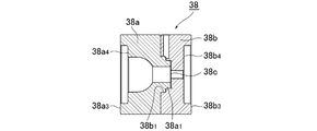
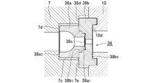
- FIG. 18 shows an example of a gasket-integrated orifice plate 38 with the ultrathin metal plate, having an orifice base 38a and the fitting recess 38b 1 provided with a fitting projection 38a 1
- the orifice base 38b is combined, and an orifice plate 38c made of a thin metal plate is sandwiched between the inner end faces in an airtight manner, and both end faces 38a 3 , 38b 3 or 38a 4 , 38b 4 of both the orifice bases 38a, 38b are attached. This is the gasket sealing surface.
- FIG. 18 the inner end surface 38d of the outer periphery thereof with a larger than the outer diameter of the orifice base 38a provided with a fitting projection 38a 1 the outer diameter of the orifice base 38b provided with a fitting recessed portion 38b 1 Is also a sealing surface.
- the gasket-integrated orifice plate 38 is inserted into the orifice housing recess 7 c formed on the downstream end face of the valve body 7, for example, as shown in FIG. 18, and pushes the outlet side block 10 to the valve body 7.
- the confidentiality of the gasket-integrated orifice plate is maintained by the seal surfaces 38a 3 , 38b 3 , and 38d.
- reference numerals 7d, 7e, and 10d denote annular projections that bite into the respective sealing surfaces to enhance the sealing function.
- the gasket-integrated orifice plate 38 shown in FIGS. 16 and 18 is an extremely thin metal plate or metal film because the orifice plate 38c is fitted and sandwiched between the orifice bases 38a and 38b in an airtight manner. Can also be sandwiched between the orifice bases 38a, 38b without deformation. Therefore, it is possible to use an orifice plate 38c having a highly accurate orifice, and by using the outer ends of both orifice bases as a sealing surface, the gasket-integrated orifice plate 38 itself can be tightly connected to a conduit or the like as a gasket. It can be clamped and fixed, and has excellent practical utility.
- the sealing surface 38d can seal the orifice plate 38c. Excellent effects such as being able to completely prevent leakage from the outside to the outside can be obtained.
- the gasket-integrated orifice plate 38 of FIGS. 16 to 18 has many excellent effects, but many problems to be solved still remain. Among them, it is an urgent issue to prevent the flow rate characteristics from fluctuating due to the change in the shape of the orifice due to the corrosion of the metal orifice plate 38c.
- an ultra-thin metal plate with a thickness of 30 to 1000 ⁇ m for example, SUS316L-P (W melt) or NK clean with less impurities). Z or the like) is used to form a circular hole having an inner diameter of 10 to 500 ⁇ m. Therefore, the orifice plate 38c is relatively easily corroded or eroded by the fluid contact flow, and particularly when the fluid is a corrosive gas such as an ozone-containing gas, a chlorine-containing gas, or a hydrogen bromide-containing gas.
- a corrosive gas such as an ozone-containing gas, a chlorine-containing gas, or a hydrogen bromide-containing gas.
- the present invention provides an orifice plate made of a very thin metal plate.
- the configuration is used. For this reason, the corrosion resistance of the orifice plate is relatively low.
- the replacement frequency of the gasket-integrated orifice plate is significantly increased. This is a solution to the problems such as inability to control and (II) increase in the frequency of replacement of the gasket-integrated orifice plate, leading to increased repair costs.
- a gasket-integrated ceramic orifice plate includes, as a first side, a first orifice base having a fitting projection and a through-passage in the center, A combination of a second orifice base having a joint recess and having a penetrating passage communicating with the passage of the first orifice base at the center, and between the end surfaces of the first orifice base and the second orifice base A ceramic orifice plate is inserted in an airtight manner, and the outer end surfaces of the first and second orifice bases are used as gasket sealing surfaces.
- the outer diameter of one of the first and second orifice bases is larger than the outer diameter of the other orifice base, and the outer peripheral edge portion of the inner end face of the one orifice base is a sealing surface. It is good.
- the ceramic orifice plate is centered on an orifice communicating with the first orifice base passage and the second orifice base passage, and the first orifice base fitting projection and the second orifice base You may insert it airtightly between the recessed parts for fitting of an orifice base.
- the ceramic orifice plate is made of a ceramic containing zirconia, has a thickness of 500 to 1000 ⁇ m, a hole diameter of 10 to 500 ⁇ m, and the fitting protrusion is pressed into the fitting recess by a pressure input of 6 kN to 10 kN.
- the ceramic orifice plate may be inserted in an airtight manner between the fitting protrusion and the fitting recess.
- Both surfaces of the circular ceramic orifice plate may be used as polishing mirror surfaces, and the contact surfaces of the fitting protrusions and the fitting recesses contacting the ceramic orifice plates may be used as polishing mirror surfaces.
- the gasket-integrated ceramic orifice plate according to the present invention has, as a second side surface, a first orifice base having a fitting projection on the inner end face and a through-passage in the center, and fitting on the inner end face.
- a second orifice base having a recess and having a through-passage in the central portion, a through-passage communicating with the first and second orifice base passages in the central portion, and the first orifice on one end surface
- the fitting projection of the orifice base is provided with a fitting recess that is fitted in an airtight manner, and a fitting projection that is fitted in an airtight manner in the fitting recess of the second orifice base is provided on the other end surface.
- a second ceramic orifice plate that is inserted in an airtight manner between the intermediate orifice base and the second orifice base and has an orifice formed in the center thereof, and is disposed in a fluid passage The outer end surfaces of the first and second orifice bases are used as sealing surfaces, respectively, and the outer diameter of one of the first and second orifice bases is set to the outside of the other orifice base and the intermediate orifice base.
- the outer peripheral edge portion of the inner end face of the one orifice base is made larger than the diameter, and the outer peripheral edge portion of the one orifice base is used as a sealing surface, and a branch passage 5d communicating with the passage of the intermediate orifice base is formed in the intermediate orifice base.
- the second ceramic orifice plate is formed with an orifice communicating with the passage of the first orifice base and the passage of the intermediate orifice base at the center, and the fitting protrusion of the first orifice base and the intermediate You may insert it airtightly between the recessed parts for fitting of an orifice base.
- the second ceramic orifice plate is formed with an orifice communicating with the passage of the intermediate orifice base and the passage of the second orifice base at the center, and the concave projection and the fitting projection of the intermediate orifice base It may be inserted in an airtight manner between the fitting recess of the second orifice base.
- the first ceramic orifice plate is made of ceramic containing zirconia, has a thickness of 500 to 1000 ⁇ m, a hole diameter of 10 to 500 ⁇ m, and the fitting orifice of the first orifice base is the second orifice.
- the first ceramic orifice plate is press-fitted into the fitting recess of the base by a pressure input of 6 to 10 kN, and the first ceramic orifice plate is interposed between the fitting projection of the first orifice base and the fitting recess of the intermediate orifice base. It may be inserted in an airtight manner.
- the second ceramic orifice plate is made of a ceramic containing zirconia, has a thickness of 500 to 1000 ⁇ m, a hole diameter of 10 to 500 ⁇ m, and a fitting protrusion of the intermediate orifice base is formed on the second orifice base.
- the second ceramic orifice plate is hermetically sealed between the fitting projection of the intermediate orifice base and the fitting recess of the second orifice base by press-fitting into the fitting recess with a pressure of 6 to 10 kN. It is intended to be inserted into the.
- the orifice plate located upstream may have a smaller diameter than the orifice plate located downstream.
- both surfaces of the circular first and second ceramic orifice plates are used as polishing mirror surfaces, and are in contact with the first and second ceramic orifice plates.
- the contact surfaces of the first orifice base fitting protrusion and the second orifice base fitting recess may be a polishing mirror surface.
- the gasket-integrated orifice plate according to the present invention includes, as the third side surface, a third orifice base having fitting recesses on both side surfaces and a through-passage in the center, and a fitting protrusion. And a fourth orifice base and a fifth orifice base which are inserted into the fitting recesses in opposite directions, and a ceramic mounted in the passage of the third orifice base.
- the outer end surfaces of the fourth and fifth orifice bases are used as gasket sealing surfaces.
- annular protrusion is provided on an outer peripheral surface of the fitting protrusion of the fourth and fifth orifice bases, and an annular protrusion is provided on a tip surface of the fitting protrusion,
- the annular protrusion on the outer peripheral surface of the fitting protrusion improves airtightness between the fitting protrusion and the fitting recess, and the fitting protrusion and the engagement protrusion by the annular protrusion on the front end surface of the fitting protrusion. It is good also as a structure which improves the airtightness between ceramic orifice plates.
- the ceramic orifice plate is made of ceramic containing a thick disc-shaped zirconia, and the fitting protrusions are pressed into the fitting recesses by 6 to 10 kN.
- the ceramic orifice plate may be inserted in an airtight manner between the front end surfaces of the fitting protrusions.
- the ceramic orifice plate is formed into a gasket-integrated ceramic orifice plate by tightly fitting and contacting the ceramic orifice plate between the first orifice base and the second orifice base. .
- a gasket-integrated ceramic orifice plate can be formed.
- the outer end surface of the first and second orifice bases, or the outer end surface of the first and second orifice bases and the outer peripheral portion of the inner end surface of one of the first and second orifice bases By using it as a sealing surface, the orifice base can be tightly tightened and fixed to a pipe line or the like as a gasket.
- a ceramic having a thickness of 500 to 1000 ⁇ m and a hole diameter of 10 to 500 ⁇ m is provided between the fitting protrusion of the first orifice base and the fitting recess of the second orifice base.
- An orifice plate is inserted, the fitting protrusion is press-fitted into the fitting recess by a pressure input of 6 kN to 10 kN, and a ceramic orifice plate is sandwiched between the two in an airtight manner.
- the contact surfaces of the fitting protrusions and the fitting recesses that are in contact with both surfaces and the ceramic orifice plate are used as polishing mirror surfaces.
- a gasket-integrated ceramic orifice plate with a highly accurate orifice and excellent corrosion resistance can be easily manufactured, and the contact surface between the ceramic orifice plate and the fitting protrusion and the fitting recess, and the fitting protrusion and the fitting It is possible to manufacture a gasket-integrated ceramic orifice plate that substantially eliminates leakage from the contact surface of the combined recess.
- a fitting recess that is fitted to the fitting protrusion of the first orifice base is provided on one end surface between the first orifice base and the second orifice base.
- an intermediate orifice base provided with a fitting protrusion to be fitted in the fitting recess of the second orifice base is provided on the other end surface, and the fitting orifice of the first orifice base and the intermediate orifice base are provided.
- a diversion passage communicating with the passage of the intermediate orifice base is formed.
- the first ceramic orifice plate and the second ceramic orifice plate have different hole diameters, and by controlling the fluid supply to the passage, a gasket-integrated ceramic orifice having a plurality of flow characteristics. It can be a plate.
- a third orifice base having fitting recesses on both side surfaces and having a penetrating passage in the center, and a fitting protrusion and having a penetrating passage in the center.
- the gasket-integrated ceramic orifice plate of the present invention when used in a pressure type flow rate control device or the like, the orifice plate can be replaced very easily, and airtightness can be secured and deformation can be prevented in mounting the orifice plate.
- the flow rate can be controlled with high accuracy because the ceramic orifice plate has high corrosion resistance.
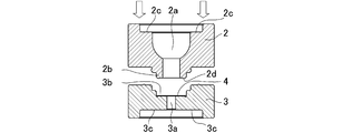
- FIG. 1 and 2 show a first embodiment of a gasket-integrated ceramic orifice plate according to the present invention.
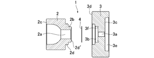
- 3 and 4 show a second embodiment of the gasket-integrated ceramic orifice plate according to the present invention.
- 5 shows a pressure type flow rate control apparatus using the gasket-integrated ceramic orifice plate of FIG. 3
- FIG. 6 is a partially enlarged view of the insertion portion of the gasket-integrated ceramic orifice plate of FIG. It is.
- the gasket-integrated ceramic orifice plate 1 of the first embodiment shown in FIG. 1 and the gasket-integrated ceramic orifice plate 1 of the second embodiment shown in FIG. 3 are the second orifice base 3 on the downstream side.
- the form of is slightly different.
- the gasket-integrated ceramic orifice plate 1 of the first embodiment of FIG. 1 and the gasket-integrated ceramic orifice plate 1 of FIG. 3 are the same as those of the conventional FIG. 15 except that the material of the orifice plate 4 is different. And it is substantially the same as the gasket-integrated orifice plate shown in FIG. Accordingly, here, an embodiment of the present invention will be described based on the gasket-integrated ceramic orifice plate 1 of the second embodiment described in FIGS. 3 and 4.
- the gasket-integrated ceramic orifice plate 1 has a convex first orifice base 2 having a through passage 2a at the center and a fitting projection 2b on the inner end face.
- a concave second orifice base 3 having a larger diameter than the first orifice base 2 and having a through-passage 3a in the center and a fitting recess 3b on the inner end surface, and an orifice ( And a ceramic orifice plate 4 formed with a convex first orifice base 2 and a concave second orifice base 3, and a ceramic orifice plate between the two orifice bases 2, 3.
- Sealing surface 2c of over preparative 1, 3c, and 3d it is obtained by a structure for preventing leakage to the outside from the sealing portion of the ceramic orifice plate 4.
- the convex first orifice base 2 is formed of a stainless material (SUS316L-P (W melt)) into a short cylindrical shape having a convex longitudinal cross-sectional shape.
- a through-shaped passage 2a having an inner peripheral surface stepped is formed at the center.
- a cylindrical fitting projection 2b having an outer peripheral surface formed in a stepped manner is provided on the inner end surface of the convex first orifice base 2 (the end surface facing the concave second orifice base 3). It is formed to protrude concentrically with the passage 2a.
- annular projections 2d and 2d ′ (FIG.
- the convex first orifice base 2 has an annular outer end surface that functions as a seal surface 2c of the gasket-integrated ceramic orifice plate 1.
- the concave second orifice base 3 is formed of a stainless steel material (SUS316L-P (W melt)) in the shape of a thick disk having a concave vertical cross-sectional shape. Is formed with a penetrating passage 3a communicating with the passage 2a of the convex first orifice base 2. Further, the fitting protrusion 2b of the convex first orifice base 2 is fitted in an airtight manner on the inner end surface of the concave second orifice base 3 (the end surface facing the convex orifice base 2). The recessed portion 3b for fitting is formed concentrically with the passage 3a.
- SUS316L-P W melt
- the inner peripheral surface of the fitting recess 3b is formed on a stepped inner peripheral surface so that the fitting protrusion 2b of the convex first orifice base 2 is fitted in an airtight manner.
- a ceramic orifice plate 4 is sandwiched between the annular projection 2d 'of the first orifice base 2 and the end face of the fitting recess 3b when the first orifice base 2 is combined with the convex first orifice base 2.
- An annular protrusion 3f (see FIG. 4) arranged so as to exhibit a sealing function is formed.
- a circular recess 3e is formed concentrically with the passage 3a on the outer end surface of the second orifice base 3 provided with the fitting recess 3b for receiving the fitting protrusion 2b.
- the bottom surface of the recess 3e formed on the outer end surface of the orifice base 3 serves as the seal surface 3c of the gasket-integrated orifice plate 1.
- the recess 3e is intended to facilitate the alignment (axial alignment) of the gasket-integrated orifice plate 1 and to protect the sealing surface 3c.
- the bottom surfaces of the fitting protrusions 2b and the fitting recesses 3b that contact a ceramic orifice plate 4 described later are finished to a so-called polishing mirror surface by electrolytic polishing or the like.
- the second orifice base 3 located on the downstream side of the first orifice base 2 and the second orifice base 3 has a first outer diameter located on the upstream side.
- the outer peripheral edge portion of the inner end surface of the second orifice base 3 located on the downstream side functions as the seal surface 3d of the gasket-integrated orifice plate 1. It has come to fulfill.
- the outer diameter of the concave second orifice base 3 located on the downstream side is larger than the outer diameter of the convex first orifice base 2 located on the upstream side.
- the outer peripheral edge portion of the inner end surface of the concave second orifice base 3 is formed as the seal surface 3d of the gasket-integrated orifice plate 1, but the outer diameter of the second orifice base 3 is the first diameter. It is also possible to omit the sealing surface 3d with the same diameter as the outer diameter of the orifice base 2, and the structure is the gasket integrated ceramic orifice plate of the first embodiment shown in FIGS. It is.
- the ceramic orifice plate 4 is formed into a very thin circular plate of a ceramic material containing zirconia, and communicates with the passages 2a and 3a of the first orifice base 2 and the second orifice base 3 at the center thereof.
- An orifice (not shown) having a desired inner diameter is formed.
- the size of the ceramic orifice plate 4 is set to a size that can be accommodated in the small-diameter portion of the fitting recess 3 b of the concave second orifice base 3.
- the shape of the ceramic orifice plate 4 may be circular or other shapes.
- the ceramic orifice plate 4 has a thickness of 500 to 1000 ⁇ m and a hole diameter (orifice diameter) of 10 to 500 ⁇ m, and both outer surfaces thereof are mirror-finished by lapping polishing or the like.
- the fitting projection 2b is pressed into the fitting recess 3b with a pressure input of 6 kN to 10 kN, and is sandwiched between the fitting projection 2b and the fitting recess 3b.
- the ceramic orifice plate 4 is accommodated in the fitting concave portion 3b of the concave second orifice base 3, and the fitting projection 2b of the convex first orifice base 2 is formed into the concave first shape.
- a gasket-integrated ceramic orifice plate is formed by press-fitting the orifice base 3 into the fitting recess 3b of the orifice base 3 by a press machine having a thrust of about 9 kN and integrating the orifice bases 2 and 3 in an airtight manner.
- the outer peripheral surface of the fitting protrusion 2b is in airtight contact with the inner peripheral surface of the fitting recess 3b, and both surfaces of the ceramic orifice plate 4 are connected to the annular protrusion 2d 'of the first orifice base 2 and the second protrusion 2d'. Since the ceramic orifice plate 4 is inserted and held between the inner end surfaces of the orifice bases 2 and 3 by being sandwiched between the annular protrusions 3f of the orifice base 3, a better sealing performance is secured. It will be. Further, the annular protrusion 2d on the outer peripheral surface of the orifice base 2 is inserted and held in a more airtight manner.
- FIG. 5 shows an example in which the gasket-integrated ceramic orifice plate 1 according to the second embodiment is applied to a pressure type flow control device, and the pressure type flow control device is a piezoelectric element drive type control valve 6.
- the pressure type flow control device is a piezoelectric element drive type control valve 6.
- an inlet side block 8 which is fastened and fixed to the upstream side of the body 7 of the control valve 6 by a bolt (not shown) and forms an inlet side fluid passage 8a communicating with the fluid passage 7a on the upstream side of the body 7, and the body 7
- a gasket-type filter 9 interposed between the inlet block 8 and the inlet-side block 8, and fastened and fixed to the downstream side of the body 7 of the control valve 6 by bolts (not shown).
- An outlet side block 10 having an outlet side fluid passage 10a communicating with the fluid passage 7b is interposed between the body 7 and the outlet side block 10, and between the two, A gasket-integrated ceramic orifice plate 1 for controlling the flow rate to be installed, a pressure sensor 11 which is disposed in the body 7 of the control valve 6 and detects the pressure on the upstream side of the gasket-integrated ceramic orifice plate 1, and a control valve 6
- the control valve 12 is controlled to adjust the opening and closing of the control valve 6 while calculating the flow rate passing through the orifice due to the upstream pressure of the gasket-integrated ceramic orifice plate 1 to control the orifice of the ceramic orifice plate. It controls the flow rate of fluid passing through. Since the pressure type flow rate control device itself shown in FIG. 5 is well known, detailed description thereof is omitted here.
- the gasket-integrated ceramic orifice plate 1 is accommodated in orifice storage recesses 7c and 10b formed on the downstream end surface of the body 7 of the control valve 6 and the upstream end surface of the outlet side block 10, 7 and the outlet side block 10 are fastened and fixed, whereby the gasket-integrated ceramic orifice plate 1 is housed and fixed in the orifice housing recesses 7c and 10b.
- the orifice housing recess 7c formed on the downstream end surface of the body 7 is formed as a stepped recess whose inner diameter changes midway, and the orifice housing recess 7c has an inner diameter of
- an annular protrusion 7d is formed that bites and seals in a tight manner on the seal surface 2c formed on the outer end surface of the first orifice base 2.
- an annular projection 7e is formed on the bottom surface of the large-diameter portion of the orifice housing recess 7c so as to bite and seal the seal surface 3d formed on the inner end surface of the second orifice base 3 in a close state.
- the orifice housing recess 10b formed on the upstream end face of the outlet side block 10 is formed in an annular recess surrounding the inlet side of the outlet side fluid passage 10a, and the bottom surface of the orifice housing recess 10b.
- An annular protrusion 10d is formed on the end face of the gasket holding protrusion 10c so as to bite and seal the seal face 3c formed on the outer end face of the concave second orifice base 3 in close contact.
- the height of the gasket holding projection 10c on the bottom surface of the orifice housing recess 10b is such that when the body 7 and the outlet side block 10 are fastened and fixed with bolts, the A surface in FIG.
- the leak amount between the A surface and the seal portion of the ceramic orifice plate 4 is 1 ⁇ 10 ⁇ 4 Pa ⁇ m 3 / sec or less
- the leak amount between the B surface and the C surface that are external leaks is 1 ⁇ 10 ⁇ 10 Pa.
- Each is set to be m 3 / sec or less.
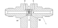
- the test gasket-integrated ceramic orifice plate includes two fourth and fifth orifice bases B1 and B2 having fitting protrusions 2b, and both side surfaces. Are formed by combining and integrating a third orifice base A provided with a fitting recess 3b and a ceramic orifice plate 4 respectively.
- the fitting protrusions 2b and 2b of the fourth and fifth orifice bases B1 and B2 are press-fitted into the fitting recesses 3b and 3b on both side surfaces of the third orifice base A, and the ceramic orifice plate 4 is sandwiched between the fitting projections 2b and 2b, so that the ceramic orifice plate 4 is kept airtight between the fitting projections 2b and 2b, and the outer peripheral surface of the fitting projection 2b It is set as the structure which airtightly presses between the internal peripheral surfaces of the recessed part 3b for fitting.
- C is a leak detection hole
- the total length between the outer surfaces of the test orifice is 8.8 mm
- the diameter of the orifice base is 10 mm
- the diameter of the ceramic orifice plate 4 is 3.5 mm
- the ceramic The orifice plate 4 has a thickness of 1.5 mm and an orifice diameter of 100 ⁇ m.
- 2d and 2d ′ are annular projections provided on the outer peripheral surface of the fitting projection 2b.
- the annular projection 2d ′ is The airtightness between the outer peripheral surface of the fitting projection 2b and the inner peripheral surface of the fitting recess 3b, and the annular projection 2d ′ provides the airtightness between the end surface of the fitting projection 2b and the side surface of the ceramic orifice plate 4. , Each increase the effect.
- the fitting protrusions 2b of the fourth and fifth orifice bases B1 and B2 and the fitting recess 3b of the third orifice base A are formed.
- the form is the same as in FIGS. 1 to 4, and three types of gasket-integrated ceramic orifice plates for leak testing, wherein the thrust for pressing the fitting protrusion 2b into the fitting recess 3b is 7 kN, 8 kN, and 9 kN. It was created.
- a leak test gasket-integrated ceramic orifice plate is set on the leak inspection jig L, and a bolt tightening mechanism (not shown) of the leak inspection jig L is adjusted to provide for the leak test.
- the bolt tightening torque applied to the gasket-integrated orifice plate was changed, and the leak level from each leak detection hole at each bolt tightening torque was measured.
- Table 1 below shows the results of the leak test. Even when the bolt tightening torque (kgf ⁇ cm) is increased, the leak level is 10 ⁇ 5 Pa ⁇ m 3 / sec to 10 ⁇ 8 Pa. ⁇ It was about m 3 / sec, and the leak level of the leak test gasket-integrated orifice plate was unstable, which proved impossible to be put to practical use.
- the inner and outer surfaces of the fitting protrusion 2b of the orifice base B and the fitting recess 3b of the orifice base A and the end surface contacting the ceramic orifice plate 4 have a surface roughness level of mirror polishing by precision machining.
- the outer surface of the ceramic orifice plate 4 is finished to a level of mirror polishing by precision polishing.
- the gasket-integrated ceramic orifice plate used for the test was disassembled, and the seal portion was enlarged and observed with a microscope, and SEM observation was also performed.
- the polishing accuracy of the fitting protrusion 2b of the orifice base A and the fitting recess 3b of the fourth and fifth orifice bases B1 and B2 is low, the polishing accuracy of the outer surface of the ceramic orifice plate 4 is low, and It has been found that the presence of material depressions on the polished surface of the ceramic orifice plate 4 is the main cause of a high leak level.
- FIG. 9 and 10 show the end face of the fitting protrusion 2b of the third orifice base A that contacts the ceramic orifice plate 4 and the bottom face of the fitting recess 3b of the fourth and fifth orifice bases B1 and B2. In both cases, it was found that poor polishing of the end face was the cause of the high leak level.
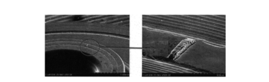
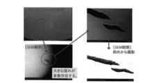
- FIG. 11 and FIG. 12 show the state of the outer surface of the ceramic orifice plate 4, and it has been found that the large material depression present in the ceramic orifice plate 4 from the beginning is the cause of the high leak level. .
- the material dents are considerably deep as can be seen from FIG. 12, and there are many that are difficult to completely remove even if the polishing accuracy of the outer surface of the ceramic orifice plate 4 is increased. Turned out to be.
- the inventors of the present invention finish the inner and outer surfaces of the fitting protrusion 2b of the first orifice base 2 and the fitting recess 3b of the second orifice base 3 to a mirror surface by electrolytic polishing or the like, After the ceramic orifice plate 4 is mirror-finished by lapping polishing or the like, the presence or absence of a material depression is further confirmed by magnifying observation using a microscope or the like, and the ceramic orifice plate 4 having no material depression is selected and used. It was to be.
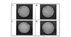
- FIG. 13 shows the selected ceramic orifice plate 4 after the presence or absence of the material depression is confirmed by magnifying observation.
- Table 2 below is for testing manufactured using the first and second orifice bases 2 and 3 mirror-polished as described above, and the ceramic orifice plate 4 that is selected for the presence of mirror polishing and material depression. The result of the leak test about a gasket integrated ceramic orifice plate is shown. There are three types of gasket-integrated shellac orifice plates used in the test, and the ceramic orifice plate 4 is sandwiched and fixed by any pressure input.
- the leak level is stable in any of the test gasket-integrated ceramic orifice plates, and the leak level itself is within an allowable range. It turned out to be possible.
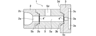
- FIGS. 14 and 15 show a third embodiment of the gasket-integrated ceramic orifice plate according to the present invention. Only the intermediate orifice base 5 is used in the first embodiment shown in FIGS. And the only difference is the gasket-integrated ceramic orifice plate according to the second embodiment, and the other configurations are almost the same.
- the gasket-integrated ceramic orifice plate 1 includes a first orifice base 2 having a through-passage 2a at the center and a fitting protrusion 2b on the inner end surface, and a center.
- a second orifice base 3 having a penetrating passage 3a and having a fitting recess 3b on the inner end face, a penetrating passage 5a in the center, and a fitting recess 5b on one end face.
- an intermediate orifice base 5 having a fitting projection 5c on the other end face, and two first and second ceramic orifice plates for small flow and large flow with an orifice (not shown) formed in the center.
- the gasket-integrated ceramic orifice plate 1 is formed with a branch flow passage 5d communicating with the passage 5a of the intermediate orifice base 5 in a branched manner in the intermediate orifice base 5, and the first orifice base 2 and the intermediate orifice base 5
- the first ceramic orifice plate 4 'for small flow rate is inserted between the second orifice base 3 and the intermediate orifice base 5 between the second orifice base 3 and the intermediate orifice base 5.
- the first orifice base 2 is formed of a stainless steel material (SUS316L-P (W melt)) into a columnar shape having a short vertical cross-section, and has an inner portion at the center.
- a penetrating passage 2a having a stepped peripheral surface is formed.
- a cylindrical fitting protrusion 2b having an outer peripheral surface formed in a stepped manner is formed on the inner end surface (the end surface facing the intermediate orifice base 5) of the first orifice base 2 so as to protrude concentrically with the passage 2a.
- annular projections 2d and 2d ′ are formed, each of which exhibits a sealing function when combined with the intermediate orifice base 5. Furthermore, the first orifice base 2 has an annular outer end surface that functions as a sealing surface 2 c of the gasket-integrated ceramic orifice plate 1.
- the second orifice base 3 is formed of a stainless steel material (SUS316L-P (W melt)) in the shape of a thick disk having a concave longitudinal cross-sectional shape.
- the passage 3a is formed.
- a fitting recess 3b into which the fitting protrusion 5c of the intermediate orifice base 5 is fitted in an airtight manner is formed concentrically with the passage 3a.
- the inner peripheral surface of the fitting recess 3b is formed on a stepped inner peripheral surface so that the fitting protrusion 5c of the intermediate orifice base 5 is fitted in an airtight manner.
- a circular recess 3e is formed concentrically with the passage 3a on the outer end surface of the concave second orifice base 3, and the concave formed on the outer end surface of the concave second orifice base 3 is formed.
- the bottom surface of the location 3e functions as the sealing surface 3c of the gasket-integrated ceramic orifice plate 1.
- the recess 3e serves to facilitate alignment (axial alignment) of the gasket-integrated ceramic orifice plate 1 and protect the sealing surface 3c.
- the intermediate orifice base 5 is formed of a stainless material (SUS316L-P (W melt)) in the shape of a cylinder having the same diameter as the outer diameter of the first orifice base 2, and has a central portion. Is formed with a through passage 5a communicating with the passage 2a of the first orifice base 2 and the passage 3a of the second orifice base 3.
- a fitting recess 5b into which the fitting protrusion 2b of the first orifice base 2 is fitted in an airtight manner is formed concentrically with the passage 5a on one end face of the intermediate orifice base 5.
- the inner peripheral surface of the fitting recess 5b is formed on a stepped inner peripheral surface so that the fitting protrusion 2b of the first orifice base 2 is fitted in an airtight manner.
- a cylindrical fitting projection 5c having a stepped outer peripheral surface that is airtightly fitted into the fitting recess 3b of the second orifice base 3 is provided on the other end surface of the intermediate orifice base 5. It is formed to protrude concentrically with 5a. On the outer peripheral surface on the large diameter side of the protrusion 5c for fitting and the end face of the protrusion 5c for fitting, annular protrusions 5e and 5e 'that exhibit a sealing function when combined with the second orifice base 3 are formed. Yes.
- a branch passage 5 d that communicates with the passage 5 a of the intermediate orifice base 5 in a branched manner is formed in the peripheral wall portion of the intermediate orifice base 5.
- first and second ceramic orifice plates 4 ′ and 4 ′′ for the small flow rate and the large flow rate are formed in the same form using the same material as in the first and second embodiments.
- both the first and second orifice plates 4 ′ and 4 ′′ may have a circular or other shape.
- the gasket-integrated ceramic orifice plate according to the present invention has excellent corrosion resistance due to the use of a ceramic orifice plate, and exhibits stable flow control characteristics even when used in corrosive gas pipelines.
- the airtightness between the ceramic orifice plate and the metal end face can ensure a seal level sufficient to withstand practical use, and has excellent practical utility.
- the present invention can be used not only for pressure type flow control devices but also for all pipes and devices that handle corrosive fluids.
Landscapes
- Engineering & Computer Science (AREA)
- Physics & Mathematics (AREA)
- General Physics & Mathematics (AREA)
- Fluid Mechanics (AREA)
- General Engineering & Computer Science (AREA)
- Mechanical Engineering (AREA)
- Measuring Volume Flow (AREA)
- Gasket Seals (AREA)
- Automation & Control Theory (AREA)
- Pipe Accessories (AREA)
- Micromachines (AREA)
- Sliding Valves (AREA)
Abstract
Description
しかし、上記のように直接に締付け固定する形式のオリフィスプレートは、締付け時に金属薄板が変形することがあるため、金属薄板の厚さを大幅に小さくすることができない。そのため、所望の形態及び孔径を得やすい薄板を用いて、高精度な流量特性のオリフィスプレートを容易に製造することができないと云う問題がある。
尚、図18に於いて、7d、7e、10dは各シール面へ食い込んでシール機能を高めるための環状突起である。
そのため、オリフィスプレート38cが流体の接触流動により比較的容易に腐食若しくは浸食されることになり、特に、流体がオゾン含有ガスや塩素含有ガス、臭化水素含有ガス等の腐食性ガスの場合には、オリフィスの径や形態が大きく変化することになり、流量制御装置等に用いるガスケット一体型オリフィスプレート38の場合には、流量制御装置の流量制御精度が大幅に低下する等の不都合が生じることになる。
また、前記第1及び第2のオリフィスベースの外側端面、又は、前記第1及び第2のオリフィスベースの外側端面と前記第1及び第2のオリフィスベースの一方のオリフィスベースの内側端面外周部をシール面として利用することにより、オリフィスベースをガスケットとして緊密に管路等へ締込み固定することができる。
その結果、高精度なオリフィスを有する耐食性に優れたガスケット一体型セラミックオリフィスプレートが容易に製作できると共に、セラミック製オリフィスプレートと嵌合用突部及び嵌合用凹部の接触面や、嵌合用突部と嵌合用凹部の接触面からのリークをほぼ皆無にしたガスケット一体型セラミックオリフィスプレートの製作が可能となる。
その結果、第1のセラミック製オリフィスプレートと第2のセラミック製オリフィスプレートの其々の孔径を違えると共に、前記通路への流体供給を制御することにより、複数の流量特性を有するガスケット一体型セラミックオリフィスプレートとすることができる。
図1及び図2は、本発明に係るガスケット一体型セラミックオリフィスプレートの第1実施形態を示す。また、図3及び図4は、本発明に係るガスケット一体型セラミックオリフィスプレートの第2実施形態を示すものである。更に、図5は、図3のガスケット一体型セラミックオリフィスプレートを用いた圧力式流量制御装置を示すものであり、図6は、図5のガスケット一体型セラミックオリフィスプレートの挿着部の部分拡大図である。
従って、ここでは、図3及び図4に記載の第2実施形態のガスケット一体型セラミックオリフィスプレート1に基づいて、本願発明の実施形態を説明する。
又、凸形の第1のオリフィスベース2の内側端面(凹形の第2のオリフィスベース3に対向する端面)には、外周面が段付に形成された筒状の嵌合用突部2bが通路2aと同心状に突出形成されている。この嵌合用突部2bの大径側の外周面及び嵌合用突部2bの端面には、凹形の第2のオリフィスベース3との組合時にシール機能を発揮する環状突起2d,2d′(図4参照)が夫々形成されている。
更に、凸形の第1のオリフィスベース2は、環状に形成された外側端面がガスケット一体型セラミックオリフィスプレート1のシール面2cとしての機能を果たすようになっている。
又、凹形の第2のオリフィスベース3の内側端面(凸形のオリフィスベース2に対向する端面)には、凸形の第1のオリフィスベース2の嵌合用突部2bが気密状に嵌合される嵌合用凹部3bが通路3aと同心状に形成されている。この嵌合用凹部3bの内周面は、凸形の第1のオリフィスベース2の嵌合用突部2bが気密状に嵌合されるように段付の内周面に形成されている。この嵌合用凹部3bの端面には、凸形の第1のオリフィスベース2との組合時に、セラミック製オリフィスプレート4を、第1のオリフィスベース2の環状突起2d′との間で狭持してシール機能を発揮するよう配置された環状突起3f(図4参照)が形成されている。
また、第2実施形態の場合は、第1のオリフィスベース2、第2のオリフィスベース3のうち、下流側に位置する第2のオリフィスベース3は、その外径が上流側に位置する第1のオリフィスベース2の外径よりも大径に形成されており、下流側に位置する第2のオリフィスベース3の内側端面の外周縁部分がガスケット一体型オリフィスプレート1のシール面3dとしての機能を果たすようになっている。
尚、セラミック製オリフィスプレート4の形状は、円形であっても、或いは他の形状であっても良い。
このとき、嵌合用突部2bの外周面が嵌合用凹部3bの内周面に気密状に密接すると共に、セラミック製オリフィスプレート4の両面が第1のオリフィスベース2の環状突起2d′と第2のオリフィスベース3の環状突起3fの間で狭持されることによって両オリフィスベース2,3の内側端面間にセラミック製オリフィスプレート4が挿着保持されるため、より良好なシール性が確保されることになる。また、オリフィスベース2の外周面にある環状突起2dによって、更に気密状に挿着保持することになる。
尚、図5に示した圧力式流量制御装置そのものは公知であるため、ここではその詳細な説明を省略する。
尚、このガスケット押え用突出部10cの端面には、凹形の第2のオリフィスベース3の外側端面に形成したシール面3cに密接状態で食い込んでシールする環状突起10dが形成されており、このガスケット押え用突出部10cを凹形の第2のオリフィスベース3の凹所3eに挿入することにより、ガスケット一体型セラミックオリフィスプレート1の位置合わせが容易に行える。
また、A面とセラミック製オリフィスプレート4のシール部のリーク量が1×10⁻⁴Pa・m3/sec以下に、外部リークとなるB面とC面のリーク量が1×10-10Pa・m3/sec以下になるように夫々設定されている。
先ず、セラミック製オリフィスプレート4と嵌合用突部2b等の金属端面間のリーク特性を主として調査するため、リーク試験に供するガスケット一体型セラミックオリフィスプレート1として、図7(a)の如きガスケット一体型セラミックオリフィスプレートを製作した。
また、図7に於ける2d、2d’は嵌合用突部2bの外周面に設けた環状突起であり、嵌合用突部2bを嵌合用凹部3b内へ圧入したときに、環状突起2d’は嵌合用突部2bの外周面と嵌合用凹部3bの内周面間の気密性を、また、環状突起2d’は嵌合用突部2bの端面とセラミック製オリフィスプレート4の側面間の気密性を、夫々高める作用をする。
尚、オリフィスベースBの嵌合用突部2bやオリフィスベースAの嵌合用凹部3bの内・外表面やセラミック製オリフィスプレート4と当接する端面は、精密機械加工により表面粗さが鏡面研磨のレベルに仕上げられており、且つセラミック製オリフィスプレート4の外表面も精密研磨加工により表面粗さが鏡面研磨のレベルに仕上げられている。

また、図11及び図12は、セラミック製オリフィスプレート4の外表面の状態を示すものであり、セラミック製オリフィスプレート4に始めから存在する大きな材料窪みが高リークレベルの原因であることが判明した。尚、この材料窪みは、図12からも明らかなように相当に深いものであり、セラミック製オリフィスプレート4の外表面の研磨精度を高めても完全に除去することの困難なものが、多数存在することが判明した。
尚、試験に供したガスケット一体型セラックオリフィスプレートは3種類であり、何れの圧入力によりセラミック製オリフィスプレート4を挟込み固定したものである。
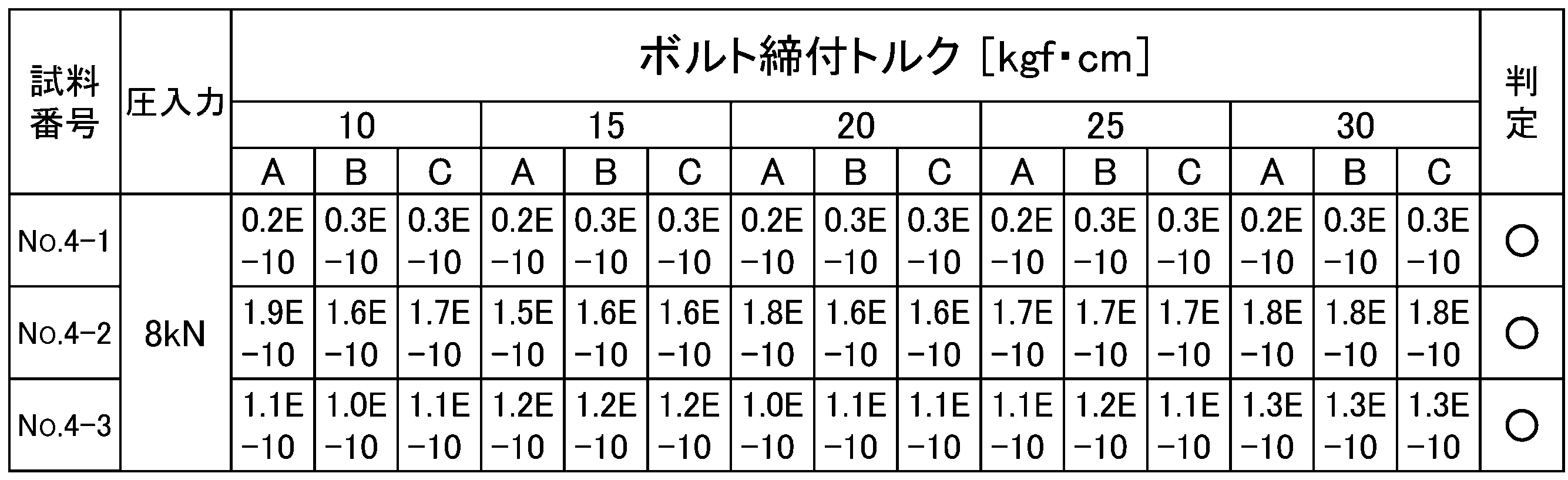
図14及び図15は、本願発明に係るガスケット一体型セラミックオリフィスプレートの第3実施形態を示すものであり、中間オリフィスベース5を用いている点のみが、図1乃至図4に示した第1及び第2実施形態に係るガスケット一体型セラミックオリフィスプレートと異なるだけであり、その他の構成は殆ど同じである。
又、第1のオリフィスベース2の内側端面(中間オリフィスベース5に対向する端面)には、外周面が段付に形成された筒状の嵌合用突部2bが通路2aと同心状に突出形成されている。この嵌合用突部2bの大径側の外周面及び嵌合用突部2bの端面には、中間オリフィスベース5との組合せ時にシール機能を発揮する環状突起2d,2d′が夫々形成されている。更に、第1のオリフィスベース2は、環状に形成された外側端面がガスケット一体型セラミックオリフィスプレート1のシール面2cとしての機能を果たすようになっている。
又、凹形の第2のオリフィスベース3の内側端面には、中間オリフィスベース5の嵌合用突部5cが気密状に嵌合される嵌合用凹部3bが通路3aと同心状に形成されている。この嵌合用凹部3bの内周面は、中間オリフィスベース5の嵌合用突部5cが気密状に嵌合されるように段付の内周面に形成されている。
又、中間オリフィスベース5の一端面には、第1のオリフィスベース2の嵌合用突部2bが気密状に嵌合される嵌合用凹部5bが通路5aと同心状に形成されている。この嵌合用凹部5bの内周面は、第1のオリフィスベース2の嵌合用突部2bが気密状に嵌合されるように段付の内周面に形成されている。
加えて、中間オリフィスベース5の周壁部分には、中間オリフィスベース5の通路5aに分岐状に連通する分流通路5dが形成されている。
2 第1のオリフィスベース
2a オリフィスベースの通路
2b オリフィスベースの嵌合用突部
2c オリフィスベースのシール面
2d 環状突起
2d’ 環状突起
3 第2のオリフィスベース
3a オリフィスベースの通路
3b オリフィスベースの嵌合用凹部
3c オリフィスベースのシール面
3d オリフィスベースのシール面
3e 凹部
3f 環状突起
4 セラミック製オリフィスプレート
4′ 小流量用の第1のセラミック製オリフィスプレート
4″ 大流量用の第2のセラミック製オリフィスプレート
5 中間オリフィスベース
5a 中間オリフィスベースの通路
5b 中間オリフィスベースの嵌合用凹部
5c 中間オリフィスベースの嵌合用突部
5d 中間オリフィスベースの分流通路
5e 環状突起
5e’ 環状突起
5f 環状突起
6 コントロール弁
7 コントロール弁のボディ
7a 流体通路
7b 流体通路
7c オリフィス収納凹所
7d 環状突起
7e 環状突起
8 入口ブロック
9 フィルタ
10 出口ブロック
10a 通路
10b オリフィス収納用凹所
10c ガスケット押え用突出部
10d 環状突起
11 圧力センサー
12 制御回路
A 第3のオリフィスベース
B1 第4のオリフィスベース
B2 第5のオリフィスベース
C リーク検出孔
D リーク検出孔
E リーク検出孔
L リーク検査冶具
Claims (15)
- 嵌合用突部を備え且つ中心部に貫通状の通路を設けた第1のオリフィスベースと、嵌合用凹部を備え且つ中心部に前記第1のオリフィスベースの通路に連通する貫通状の通路を設けた第2のオリフィスベースとを組合せ、前記第1のオリフィスベースと前記第2のオリフィスベースの端面間にセラミック製オリフィスプレートを気密状に挿着すると共に、前記第1のオリフィスベース及び前記第2のオリフィスベースの其々の外側端面をガスケットのシール面としたことを特徴とするガスケット一体型セラミックオリフィスプレート。
- 前記第1及び第2のオリフィスベースのうちの一方のオリフィスベースの外径を他方のオリフィスベースの外径よりも大径とすると共に、当該一方のオリフィスベースの内側端面の外周縁部分をシール面とした請求項1に記載のガスケット一体型セラミックオリフィスプレート。
- 前記セラミック製オリフィスプレートを、前記第1のオリフィスベースの通路及び前記第2のオリフィスベースの通路に連通するオリフィスを中心に有し、前記第1のオリフィスベースの嵌合用突部と前記第2のオリフィスベースの嵌合用凹部との間に気密状に挿着した請求項1に記載のガスケット一体型セラミックオリフィスプレート。
- 前記セラミック製オリフィスプレートをジルコニアを含有するセラミック製とし、その厚みを500~1000μm、孔径を10~500μmとすると共に、前記嵌合用突部を前記嵌合用凹部内へ6~10kNの圧入力により圧入し、前記嵌合用突部と前記嵌合用凹部との間に前記セラミック製オリフィスプレートを気密状に挿着した請求項3に記載のガスケット一体型セラミックオリフィスプレート。
- 円形状の前記セラミック製オリフィスプレートの両面を研磨鏡面とすると共に、該セラミック製オリフィスプレートに当接する前記嵌合用突部及び前記嵌合用凹部の接触面を研磨鏡面とした請求項4に記載のガスケット一体型セラミックオリフィスプレート。
- 内側端面に嵌合用突部を備え中心部に貫通状の通路を有する第1のオリフィスベースと、内側端面に嵌合用凹部を備え中心部に貫通状の通路を有する第2のオリフィスベースと、中心部に前記第1及び第2のオリフィスベースの通路に連通する貫通状の通路を有し、一端面に前記第1のオリフィスベースの嵌合用突部が気密状に嵌合される嵌合用凹部を備えると共に、他端面に前記第2のオリフィスベースの嵌合用凹部に気密状に嵌合される嵌合用突部を備えた中間オリフィスベースと、前記第1のオリフィスベースと前記中間オリフィスベースとの間に気密状に挿着され中心部にオリフィスが形成された第1のセラミック製オリフィスプレートと、前記中間オリフィスベースと前記第2のオリフィスベースとの間に気密状に挿着され中心部にオリフィスが形成された第2のセラミック製オリフィスプレートとを備え、流体通路に配設されて前記第1及び第2のオリフィスベースの外側端面を夫々シール面とすると共に、前記第1及び第2のオリフィスベースのうちの一方のオリフィスベースの外径を他方のオリフィスベース及び前記中間オリフィスベースの外径よりも大径にして該一方のオリフィスベースの内側端面の外周縁部分をシール面とし、又、前記中間オリフィスベースに該中間オリフィスベースの通路に連通する分流通路を形成したことを特徴とするガスケット一体型セラミックオリフィスプレート。
- 前記第1のセラミック製オリフィスプレートを、中心部に前記第1のオリフィスベースの通路及び前記中間オリフィスベースの通路に連通するオリフィスを有し、前記第1のオリフィスベースの嵌合用突部と前記中間オリフィスベースの嵌合用凹部との間に気密状に挿着した請求項6に記載のガスケット一体型セラミックオリフィスプレート。
- 前記第2のセラミック製オリフィスプレートを、中心部に前記中間オリフィスベースの通路及び凹形の前記第2のオリフィスベースの通路に連通するオリフィスを有し、前記中間オリフィスベースの嵌合用突部と凹形の前記第2のオリフィスベースの嵌合用凹部との間に気密状に挿着した請求項6に記載のガスケット一体型セラミックオリフィスプレート。
- 前記第1のセラミック製オリフィスプレートをジルコニアを含有するセラミック製とし、その厚みを500~1000μm、孔径を10~500μmとすると共に、前記第1のオリフィスベースの嵌合用突部を前記中間オリフィスベースの嵌合用凹部内へ6~10kNの圧入力により圧入し、前記第1のオリフィスベースの嵌合用突部と前記中間オリフィスベースの嵌合用凹部との間に前記第1のセラミック製オリフィスプレートを気密状に挿着した請求項7に記載のガスケット一体型セラミックオリフィスプレート。
- 前記第2のセラミック製オリフィスプレートをジルコニアを含有するセラミック製とし、その厚みを500~1000μm、孔径を10~500μmとすると共に、前記中間オリフィスベースの嵌合用突部を前記第2のオリフィスベースの嵌合用凹部内へ6~10kNの圧入力により圧入し、前記中間オリフィスベースの嵌合用突部と前記第2のオリフィスベースの嵌合用凹部との間に前記第2のセラミック製オリフィスプレートを気密状に挿着した請求項8に記載のガスケット一体型セラミックオリフィスプレート。
- 前記第1及び第2のオリフィスプレートのうち、上流側に位置するオリフィスプレートのオリフィスを下流側に位置するオリフィスプレートのオリフィスより小径にした請求項6に記載のガスケット一体型セラミックオリフィスプレート。
- 円形状の前記第1及び第2のセラミック製オリフィスプレートの其々の両面を研磨鏡面とすると共に、該第1及び第2のセラミック製オリフィスプレートに当接する前記第1のオリフィスベースの嵌合用突部及び前記第2のオリフィスベースの嵌合用凹部の接触面を研磨鏡面とした請求項6に記載のガスケット一体型セラミックオリフィスプレート。
- 両側面に嵌合用凹部を備え且つ中心部に貫通状の通路を有する第3のオリフィスベースと、嵌合用突部を備え且つ中心部に貫通状の通路を有すると共に、前記両嵌合用凹部内へ対向状に挿入する第4のオリフィスベース及び第5のオリフィスベースと、前記第3のオリフィスベースの通路内へ装着したセラミック製オリフィスプレートとを備え、前記嵌合用凹部内へ圧入した前記第4及び第5のオリフィスベースの先端面間で、前記第3のオリフィスベースの通路内へ装着した前記セラミック製オリフィスプレートを気密状に挟着すると共に、前記第4及び第5のオリフィスベースの外側端面をガスケットのシール面としたことを特徴とするガスケット一体型セラミックオリフィスプレート。
- 前記第4及び第5のオリフィスベースの前記嵌合用突部の外周面に環状突起を設けると共に、該嵌合用突部の先端面に環状突起を設け、前記嵌合用突部の外周面の環状突起により前記嵌合用突部と前記嵌合用凹部との間の気密性を高めると共に、前記嵌合用突部の先端面の環状突起により前記嵌合用突部と前記セラミック製オリフィスプレートとの間の気密性を高める構成とした請求項13に記載のガスケット一体型セラミックオリフィスプレート。
- 前記セラミック製オリフィスプレートを厚い円盤状のジルコニアを含有するセラミック製とすると共に、前記両嵌合用突部を前記両嵌合用凹部内へ6~10kNの圧入力により圧入し、前記両嵌合用突部の先端面間に前記セラミック製オリフィスプレートを気密状に挿着した請求項13に記載のガスケット一体型セラミックオリフィスプレート。
Priority Applications (4)
| Application Number | Priority Date | Filing Date | Title |
|---|---|---|---|
| US14/763,713 US20150362105A1 (en) | 2013-02-01 | 2014-01-24 | Gasket-integrated ceramic orifice plate |
| KR1020157010927A KR101801674B1 (ko) | 2013-02-01 | 2014-01-24 | 개스킷 일체형 세라믹 오리피스 플레이트 |
| CN201480003382.1A CN104838240A (zh) | 2013-02-01 | 2014-01-24 | 垫片一体型陶瓷孔板 |
| JP2014559556A JP6231998B2 (ja) | 2013-02-01 | 2014-01-24 | ガスケット一体型セラミックオリフィスプレート |
Applications Claiming Priority (2)
| Application Number | Priority Date | Filing Date | Title |
|---|---|---|---|
| JP2013018039 | 2013-02-01 | ||
| JP2013-018039 | 2013-02-01 |
Publications (1)
| Publication Number | Publication Date |
|---|---|
| WO2014119265A1 true WO2014119265A1 (ja) | 2014-08-07 |
Family
ID=51261983
Family Applications (1)
| Application Number | Title | Priority Date | Filing Date |
|---|---|---|---|
| PCT/JP2014/000350 Ceased WO2014119265A1 (ja) | 2013-02-01 | 2014-01-24 | ガスケット一体型セラミックオリフィスプレート |
Country Status (6)
| Country | Link |
|---|---|
| US (1) | US20150362105A1 (ja) |
| JP (1) | JP6231998B2 (ja) |
| KR (1) | KR101801674B1 (ja) |
| CN (1) | CN104838240A (ja) |
| TW (1) | TWI480521B (ja) |
| WO (1) | WO2014119265A1 (ja) |
Cited By (3)
| Publication number | Priority date | Publication date | Assignee | Title |
|---|---|---|---|---|
| JP2016205409A (ja) * | 2015-04-15 | 2016-12-08 | 株式会社フジキン | 遮断開放器 |
| JP2018028366A (ja) * | 2016-08-19 | 2018-02-22 | ウエットマスター株式会社 | オリフィスユニット及びオリフィスユニットを備えた気化式加湿器 |
| WO2021044721A1 (ja) * | 2019-09-05 | 2021-03-11 | 株式会社堀場エステック | 流量制御弁又は流量制御装置 |
Families Citing this family (3)
| Publication number | Priority date | Publication date | Assignee | Title |
|---|---|---|---|---|
| US11274687B2 (en) * | 2016-06-06 | 2022-03-15 | Trajan Scientific Australia Pty Ltd | Liquid junction assembly |
| CN111649172B (zh) * | 2020-04-16 | 2022-04-19 | 北京控制工程研究所 | 一种基于ltcc的微型化微流量控制器 |
| CN118518063B (zh) * | 2024-06-17 | 2025-07-01 | 江西万年芯微电子有限公司 | 连接组件及应用连接组件的传感器 |
Citations (4)
| Publication number | Priority date | Publication date | Assignee | Title |
|---|---|---|---|---|
| JPS6141098A (ja) * | 1984-08-02 | 1986-02-27 | 三菱重工業株式会社 | オリフイス |
| JPH0861416A (ja) * | 1994-08-23 | 1996-03-08 | Kayaba Ind Co Ltd | オイルダンパにおけるエア抜き構造 |
| JP2009115138A (ja) * | 2007-11-02 | 2009-05-28 | Nsk Ltd | シール装置 |
| JP2010151698A (ja) * | 2008-12-26 | 2010-07-08 | Fujikin Inc | ガスケット型オリフィス及びこれを用いた圧力式流量制御装置 |
Family Cites Families (2)
| Publication number | Priority date | Publication date | Assignee | Title |
|---|---|---|---|---|
| CN2741010Y (zh) * | 2004-09-05 | 2005-11-16 | 范兴宽 | 孔板流量计用耐磨耐腐蚀陶瓷孔板 |
| CN101865356A (zh) * | 2009-04-15 | 2010-10-20 | 中国恩菲工程技术有限公司 | 消能孔板 |
-
2014
- 2014-01-24 JP JP2014559556A patent/JP6231998B2/ja active Active
- 2014-01-24 KR KR1020157010927A patent/KR101801674B1/ko active Active
- 2014-01-24 US US14/763,713 patent/US20150362105A1/en not_active Abandoned
- 2014-01-24 WO PCT/JP2014/000350 patent/WO2014119265A1/ja not_active Ceased
- 2014-01-24 CN CN201480003382.1A patent/CN104838240A/zh active Pending
- 2014-01-28 TW TW103103196A patent/TWI480521B/zh not_active IP Right Cessation
Patent Citations (4)
| Publication number | Priority date | Publication date | Assignee | Title |
|---|---|---|---|---|
| JPS6141098A (ja) * | 1984-08-02 | 1986-02-27 | 三菱重工業株式会社 | オリフイス |
| JPH0861416A (ja) * | 1994-08-23 | 1996-03-08 | Kayaba Ind Co Ltd | オイルダンパにおけるエア抜き構造 |
| JP2009115138A (ja) * | 2007-11-02 | 2009-05-28 | Nsk Ltd | シール装置 |
| JP2010151698A (ja) * | 2008-12-26 | 2010-07-08 | Fujikin Inc | ガスケット型オリフィス及びこれを用いた圧力式流量制御装置 |
Cited By (10)
| Publication number | Priority date | Publication date | Assignee | Title |
|---|---|---|---|---|
| JP2016205409A (ja) * | 2015-04-15 | 2016-12-08 | 株式会社フジキン | 遮断開放器 |
| KR20170133504A (ko) * | 2015-04-15 | 2017-12-05 | 가부시키가이샤 후지킨 | 차단 개방기 |
| KR102026006B1 (ko) * | 2015-04-15 | 2019-09-26 | 가부시키가이샤 후지킨 | 차단 개방기 |
| US10753497B2 (en) | 2015-04-15 | 2020-08-25 | Fujikin Incorporated | Shutoff-opening device |
| JP2018028366A (ja) * | 2016-08-19 | 2018-02-22 | ウエットマスター株式会社 | オリフィスユニット及びオリフィスユニットを備えた気化式加湿器 |
| WO2021044721A1 (ja) * | 2019-09-05 | 2021-03-11 | 株式会社堀場エステック | 流量制御弁又は流量制御装置 |
| JPWO2021044721A1 (ja) * | 2019-09-05 | 2021-03-11 | ||
| US12025999B2 (en) | 2019-09-05 | 2024-07-02 | Horiba Stec, Co., Ltd. | Flow rate control valve and flow rate control device |
| JP7569791B2 (ja) | 2019-09-05 | 2024-10-18 | 株式会社堀場エステック | 流量制御弁又は流量制御装置 |
| TWI861190B (zh) * | 2019-09-05 | 2024-11-11 | 日商堀場Stec股份有限公司 | 流量控制閥或流量控制裝置 |
Also Published As
| Publication number | Publication date |
|---|---|
| KR101801674B1 (ko) | 2017-11-27 |
| JP6231998B2 (ja) | 2017-11-15 |
| TWI480521B (zh) | 2015-04-11 |
| KR20150060946A (ko) | 2015-06-03 |
| TW201447240A (zh) | 2014-12-16 |
| CN104838240A (zh) | 2015-08-12 |
| JPWO2014119265A1 (ja) | 2017-01-26 |
| US20150362105A1 (en) | 2015-12-17 |
Similar Documents
| Publication | Publication Date | Title |
|---|---|---|
| JP6231998B2 (ja) | ガスケット一体型セラミックオリフィスプレート | |
| JP5301983B2 (ja) | ガスケット型オリフィス及びこれを用いた圧力式流量制御装置 | |
| US4192192A (en) | Diaphragm seal assembly | |
| US10067023B2 (en) | Differential pressure measuring pickup | |
| KR102436790B1 (ko) | 압력 센서 | |
| JP5973816B2 (ja) | 高圧ガス容器のシール構造 | |
| TWI322342B (ja) | ||
| KR102208902B1 (ko) | 파이프 조인트 | |
| CN110132366B (zh) | 流量计及其孔板承载件组件 | |
| CN103608614A (zh) | 垫圈及密封结构 | |
| CN102252717B (zh) | 电磁流量计 | |
| JP5087555B2 (ja) | 流体継手 | |
| US8177238B2 (en) | System and method of a flange seal ring | |
| JPH08184393A (ja) | 管継手 | |
| JP2011123011A (ja) | ダイアフラムシール型差圧測定装置 | |
| KR102466397B1 (ko) | 배관 접속 장치 | |
| JP6341180B2 (ja) | 燃料配管構造 | |
| JP2011002233A (ja) | ダイアフラムシール型差圧測定装置 | |
| JP2013148468A (ja) | 圧力計測装置 | |
| JPH07174232A (ja) | 金属製シール材のシール方法 | |
| KR200402877Y1 (ko) | 버터플라이 밸브의 몸통시트 누설방지를 위한 장치 | |
| JP2005036857A (ja) | シール部材 | |
| JP2003202095A5 (ja) | ||
| JP2002031236A (ja) | メタルガスケット |
Legal Events
| Date | Code | Title | Description |
|---|---|---|---|
| 121 | Ep: the epo has been informed by wipo that ep was designated in this application |
Ref document number: 14746276 Country of ref document: EP Kind code of ref document: A1 |
|
| ENP | Entry into the national phase |
Ref document number: 20157010927 Country of ref document: KR Kind code of ref document: A |
|
| ENP | Entry into the national phase |
Ref document number: 2014559556 Country of ref document: JP Kind code of ref document: A |
|
| WWE | Wipo information: entry into national phase |
Ref document number: 14763713 Country of ref document: US |
|
| NENP | Non-entry into the national phase |
Ref country code: DE |
|
| 122 | Ep: pct application non-entry in european phase |
Ref document number: 14746276 Country of ref document: EP Kind code of ref document: A1 |