WO2014118963A1 - リチウムイオン二次電池用負極材料 - Google Patents
リチウムイオン二次電池用負極材料 Download PDFInfo
- Publication number
- WO2014118963A1 WO2014118963A1 PCT/JP2013/052309 JP2013052309W WO2014118963A1 WO 2014118963 A1 WO2014118963 A1 WO 2014118963A1 JP 2013052309 W JP2013052309 W JP 2013052309W WO 2014118963 A1 WO2014118963 A1 WO 2014118963A1
- Authority
- WO
- WIPO (PCT)
- Prior art keywords
- negative electrode
- formula
- group
- lithium ion
- active material
- Prior art date
- Legal status (The legal status is an assumption and is not a legal conclusion. Google has not performed a legal analysis and makes no representation as to the accuracy of the status listed.)
- Ceased
Links
Images
Classifications
-
- H—ELECTRICITY
- H01—ELECTRIC ELEMENTS
- H01M—PROCESSES OR MEANS, e.g. BATTERIES, FOR THE DIRECT CONVERSION OF CHEMICAL ENERGY INTO ELECTRICAL ENERGY
- H01M50/00—Constructional details or processes of manufacture of the non-active parts of electrochemical cells other than fuel cells, e.g. hybrid cells
- H01M50/40—Separators; Membranes; Diaphragms; Spacing elements inside cells
- H01M50/46—Separators, membranes or diaphragms characterised by their combination with electrodes
-
- H—ELECTRICITY
- H01—ELECTRIC ELEMENTS
- H01M—PROCESSES OR MEANS, e.g. BATTERIES, FOR THE DIRECT CONVERSION OF CHEMICAL ENERGY INTO ELECTRICAL ENERGY
- H01M4/00—Electrodes
- H01M4/02—Electrodes composed of, or comprising, active material
- H01M4/13—Electrodes for accumulators with non-aqueous electrolyte, e.g. for lithium-accumulators; Processes of manufacture thereof
- H01M4/137—Electrodes based on electro-active polymers
-
- H—ELECTRICITY
- H01—ELECTRIC ELEMENTS
- H01M—PROCESSES OR MEANS, e.g. BATTERIES, FOR THE DIRECT CONVERSION OF CHEMICAL ENERGY INTO ELECTRICAL ENERGY
- H01M10/00—Secondary cells; Manufacture thereof
- H01M10/05—Accumulators with non-aqueous electrolyte
- H01M10/052—Li-accumulators
- H01M10/0525—Rocking-chair batteries, i.e. batteries with lithium insertion or intercalation in both electrodes; Lithium-ion batteries
-
- H—ELECTRICITY
- H01—ELECTRIC ELEMENTS
- H01M—PROCESSES OR MEANS, e.g. BATTERIES, FOR THE DIRECT CONVERSION OF CHEMICAL ENERGY INTO ELECTRICAL ENERGY
- H01M4/00—Electrodes
- H01M4/02—Electrodes composed of, or comprising, active material
- H01M4/36—Selection of substances as active materials, active masses, active liquids
- H01M4/60—Selection of substances as active materials, active masses, active liquids of organic compounds
- H01M4/602—Polymers
- H01M4/604—Polymers containing aliphatic main chain polymers
-
- Y—GENERAL TAGGING OF NEW TECHNOLOGICAL DEVELOPMENTS; GENERAL TAGGING OF CROSS-SECTIONAL TECHNOLOGIES SPANNING OVER SEVERAL SECTIONS OF THE IPC; TECHNICAL SUBJECTS COVERED BY FORMER USPC CROSS-REFERENCE ART COLLECTIONS [XRACs] AND DIGESTS
- Y02—TECHNOLOGIES OR APPLICATIONS FOR MITIGATION OR ADAPTATION AGAINST CLIMATE CHANGE
- Y02E—REDUCTION OF GREENHOUSE GAS [GHG] EMISSIONS, RELATED TO ENERGY GENERATION, TRANSMISSION OR DISTRIBUTION
- Y02E60/00—Enabling technologies; Technologies with a potential or indirect contribution to GHG emissions mitigation
- Y02E60/10—Energy storage using batteries
Definitions
- the present invention relates to a negative electrode material for a lithium ion secondary battery.
- Patent Document 1 discloses a technique of adding a polyethylene oxide polymer to an electrode.
- Patent Document 2 discloses a technique of blending polyaniline sulfonic acids into an electrode.
- Patent Document 3 discloses a technique of blending a polymer containing a sulfonate ion group into an electrode.
- Patent Document 4 discloses a technology relating to a negative electrode material containing a carbon cluster having a sulfoalkyl group.
- Patent Document 1 when the negative electrode active material is coated with the polymers of Patent Documents 1 to 4, there is a problem that the resistance of the battery is increased and the output characteristics are degraded.
- the polyethylene oxide described in Patent Document 1 is considered to have high resistance because it has high coordination with lithium ions.
- All the polymers described in Patent Documents 2 to 4 have a sulfo group as a polar functional group.
- the sulfo group is a functional group that enhances the dissociability of lithium ions, but it is assumed that the dissociability of any polymer decreases as a result of the functional group substituting for the sulfo group, resulting in an increase in battery resistance.
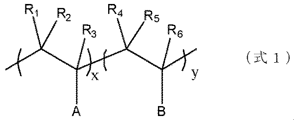
- the negative electrode active material coating material for lithium ion secondary batteries represented by (Formula 1).
- a in (Formula 1) is a functional group having an amido group (—NHCO—) and a sulfo group (—SO 3 X; X: alkali metal, H).
- B is a functional group having a polar functional group.
- R1 to R6 in (Formula 1) are a hydrocarbon group having 1 to 10 carbon atoms or H.
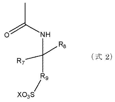
- a in (Expression 1) is represented by (Expression 2), for example.
- R7 and R8 in (Formula 2) are an alkyl group having 1 to 10 carbon atoms or H.
- R 9 in (Formula 2) is a methylene group (— (— CH 2 —) n —), and n is 0 or more and 10 or less.
- X of (Formula 2) is an alkali metal or H.
- a functional group containing a hydroxyl group, a carboxyl group, a sulfo group or an amino group can be used.
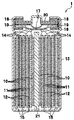
- FIG. 1 is a view schematically showing an internal structure of a battery according to an embodiment of the present invention.
- a battery 1 according to an embodiment of the present invention shown in FIG. 1 includes a positive electrode 10, a separator 11, a negative electrode 12, a battery case (ie, battery can) 13, a positive current collection tab 14, a negative current collection tab 15, an inner lid 16,
- the internal pressure release valve 17, the gasket 18, a positive temperature coefficient (PTC) resistance element 19, a battery cover 20, and an axial center 21 are provided.
- the battery lid 20 is an integrated component including the inner lid 16, the internal pressure release valve 17, the gasket 18, and the PTC resistance element 19. Further, the positive electrode 10, the separator 11 and the negative electrode 12 are wound around the axial center 21.
- the separator 11 is inserted between the positive electrode 10 and the negative electrode 12, and an electrode group wound around the axial center 21 is produced.
- the shaft 21 any known one can be used as long as it can support the positive electrode 10, the separator 11 and the negative electrode 12.
- the electrode group may be formed into various shapes, such as one obtained by laminating strip electrodes, or one obtained by winding the positive electrode 10 and the negative electrode 12 into an arbitrary shape such as flat.
- the shape of the battery case 13 may be a cylindrical shape, a flat oval shape, a flat oval shape, a square shape, or the like, in accordance with the shape of the electrode group.
- the material of the battery case 13 is selected from materials having corrosion resistance to the non-aqueous electrolyte, such as aluminum, stainless steel, nickel plated steel, and the like. Moreover, when the battery case 13 is electrically connected to the positive electrode 10 or the negative electrode 12, deterioration of the material due to corrosion of the battery case 13 or alloying with lithium ions does not occur in the portion in contact with the non-aqueous electrolyte. Thus, the material of the battery case 13 is selected.
- the electrode group is housed in the battery case 13, the negative electrode current collection tab 15 is connected to the inner wall of the battery case 13, and the positive electrode current collection tab 14 is connected to the bottom surface of the battery cover 20.
- the electrolyte is injected into the battery container interior 13 before sealing the battery.
- a method of injecting the electrolytic solution there is a method of adding directly to the electrode group in a state in which the battery cover 20 is released, or a method of adding from an injection port provided on the battery cover 20.
- the battery cover 20 is brought into close contact with the battery case 13 to seal the entire battery. If there is an electrolyte inlet, seal it as well.
- a method of sealing the battery there are known techniques such as welding and caulking.
- the lithium ion battery according to one embodiment of the present invention can be manufactured, for example, by arranging the following negative electrode and positive electrode as opposed to each other with a separator interposed therebetween, and injecting an electrolyte.
- the structure of the lithium ion battery according to one embodiment of the present invention is not particularly limited, but usually, the positive electrode and the negative electrode and the separator separating them are wound to form a wound electrode group, or the positive electrode, the negative electrode and the separator It can be stacked to form a stacked electrode group.
- the positive electrode 10 includes a positive electrode active material, a conductive agent, a binder, and a current collector.
- a positive electrode active material LiCoO 2 , LiNiO 2 , and LiMn 2 O 4 are representative examples.
- LiMnO 3 LiMn 2 O 3 , LiMnO 2 , Li 4 Mn 5 O 12 , and LiMn 2-x MxO 2
- LiFeO 2 , Fe 2 (SO 4 ) 3 LiCo 1 -x M x O 2 (where little is selected from the group consisting of
- the particle size of the positive electrode active material is usually defined to be equal to or less than the thickness of the mixture layer formed from the positive electrode active material, the conductive agent, and the binder.
- the powder of the positive electrode active material contains coarse particles having a size equal to or larger than the mixture layer thickness, the coarse particles are removed in advance by sieve classification, air flow classification, etc. to produce particles of the mixed layer thickness or less. preferable.
- the positive electrode active material is generally oxide-based and has high electrical resistance
- a conductive agent made of carbon powder is used to compensate for the electrical conductivity. Since both the positive electrode active material and the conductive agent are usually powders, the powders can be mixed with a binder to bond the powders together and simultaneously adhere to the current collector.
- an aluminum foil having a thickness of 10 to 100 ⁇ m, a perforated aluminum foil having a thickness of 10 to 100 ⁇ m and a hole diameter of 0.1 to 10 mm, an expanded metal, a foam metal plate or the like is used.
- materials such as stainless steel and titanium are also applicable.
- any current collector can be used without being limited to the material, shape, manufacturing method and the like.
- a positive electrode slurry obtained by mixing a positive electrode active material, a conductive agent, a binder, and an organic solvent is attached to a current collector by a doctor blade method, dipping method, spray method or the like, then the organic solvent is dried and added by a roll press.
- the positive electrode 10 can be manufactured by pressure molding. Moreover, it is also possible to laminate a plurality of mixture layers on the current collector by performing application to drying a plurality of times.
- the negative electrode comprises a negative electrode active material, a binder and a current collector.
- a negative electrode active material a graphitizable material obtained from natural graphite, petroleum coke, coal pitch coke or the like is heat treated at a high temperature of 2500 ° C. or higher, and is alloyed with mesophase carbon or amorphous carbon, carbon fiber or lithium
- a metal or a material having a metal supported on the surface of carbon particles is used.
- it is a metal or alloy selected from lithium, silver, aluminum, tin, silicon, indium, gallium and magnesium.
- the metal or an oxide of the metal can be used as a negative electrode active material.
- lithium titanate can also be used.
- the negative electrode active material is coated with the compound represented by (Formula 1).
- a in (Formula 1) is a functional group having an amido group (—NHCO—) and a sulfo group (—SO 3 X; X: alkali metal, H).
- B is a functional group having a polar functional group.
- R1 to R6 in (Formula 1) are a hydrocarbon group having 1 to 10 carbon atoms or H.
- X and y of (Formula 1) are composition ratios of copolymerization.
- X in -SO 3 X is an alkali metal, and for example, Li, Na, K, Rb, Cs, Fr and the like can be used. From the viewpoint of battery performance, it is preferable to use Li, Na, or K.
- the dissociative property of the polar functional group can be further enhanced, so that the effect of reducing the battery resistance can be obtained.
- R 7 and R 8 in (Formula 2) are an alkyl group or H.
- a methyl group is preferably used from the viewpoint of electrochemical stability.
- R 9 in (Formula 2) is a methylene group (— (— CH 2 —) n —), and n is 0 or more and 10 or less. From the viewpoint of ion conductivity, n is preferably 1 or more and 5 or less.
- X of (Formula 2) is an alkali metal or H.
- Formula (1) can be produced by copolymerizing a monomer containing A and a monomer containing B.
- B in (Formula 1) is a polar functional group, and for example, a functional group containing a hydroxyl group, a carboxyl group, a sulfo group, or an amino group can be used.
- functional groups containing a carboxyl group and a sulfo group are preferably used.
- these esters and alkali metal salts can also be used. Among them, alkali metal salts of carboxyl group and sulfo group do not contain active hydrogen, so the effect of the present invention is enhanced.
- the sulfo group can also be a hydroxyl group, a carboxyl group or an amino group.
- the polymerization of the monomer containing A and the copolymerization of the monomer containing A with the monomer containing B may be any of conventionally known bulk polymerization, solution polymerization and emulsion polymerization.
- the polymerization method is not particularly limited, but radical polymerization is preferably used.
- a polymerization initiator may or may not be used, and in terms of ease of handling, it is preferable to use a radical polymerization initiator.
- the polymerization method using a radical polymerization initiator can be carried out at a temperature range and polymerization time which are usually performed.
- the blending amount of the initiator in the present invention is 0.1 wt% to 20 wt%, preferably 0.3 wt% or more and 5 wt% with respect to the polymerizable compound.
- the composition ratio of the (formula 1) copolymerization is important to obtain the effects of the present invention.
- x / (x + y) is 0 ⁇ x / (x + y) ⁇ 1, preferably 0.4 ⁇ x / (x + y) ⁇ 1.
- Formula 4 As a polymer which copolymerized the monomer A and the monomer B, Formula 4 is mentioned, for example.
- the method for coating the negative electrode active material with the coating material is not particularly limited as long as the negative electrode active material is coated with a polymer, but the polymer is dissolved in a solvent and the negative electrode active material is added to the solution. It is preferable from the viewpoint of cost to dry and coat the solvent after stirring.
- the solvent is not particularly limited as long as the polymer is dissolved, but protic solvents such as water and ethanol, aprotic solvents such as N-methylpyrrolidone, and nonpolar solvents such as toluene and hexane are preferably used.
- the coating amount is an important value to obtain the present effect.
- the coating amount is 0.01 wt% or more and 10 wt% or less, preferably 0.1 wt% or more and 1% or less, and particularly preferably 0.3 wt% or more and 0.9 wt% or less with respect to the negative electrode active material.
- the separator 11 is inserted between the positive electrode 10 and the negative electrode 12 manufactured by the above-described method to prevent a short circuit of the positive electrode 10 and the negative electrode 12.
- the separator 11 it is possible to use a polyolefin-based polymer sheet made of polyethylene, polypropylene or the like, or a two-layer structure in which a polyolefin-based polymer and a fluorine-based polymer sheet represented by polyethylene tetrafluoride are welded. It is.
- a mixture of ceramics and a binder may be formed in a thin layer on the surface of the separator 11 so that the separator 11 does not shrink when the battery temperature rises. Since these separators 11 need to transmit lithium ions at the time of charge and discharge of the battery, they can generally be used in lithium ion batteries if the pore size is 0.01 to 10 ⁇ m and the porosity is 20 to 90%. .
- Lithium hexafluorophosphate LiPF 6
- LiPF 6 Lithium hexafluorophosphate
- a solvent prepared by mixing ethylene carbonate with dimethyl carbonate, diethyl carbonate, ethyl methyl carbonate or the like as a representative example of an electrolytic solution usable in one embodiment of the present invention
- lithium borofluoride LiBF 4
- the present invention is not limited to the type of solvent and electrolyte, and the mixing ratio of solvents, and other electrolytic solutions can also be used.
- nonaqueous solvents examples include propylene carbonate, ethylene carbonate, butylene carbonate, vinylene carbonate, ⁇ -butyrolactone, dimethyl carbonate, diethyl carbonate, methyl ethyl carbonate, 1,2-dimethoxyethane, 2 -Methyltetrahydrofuran, dimethylsulfoxide, 1,3-dioxolane, formamide, dimethylformamide, methyl propionate, ethyl propionate, phosphoric acid triester, trimethoxymethane, dioxolane, diethyl ether, sulfolane, 3-methyl-2-
- non-aqueous solvents such as oxazolidinone, tetrahydrofuran, 1,2-diethoxyethane, chloroethylene carbonate, or chloropropylene carbonate.
- Other solvents may be used as long as they do not decompose on the positive electrode 10 or the negative electrode
- examples of the electrolyte LiPF 6, LiBF 4, LiClO 4, LiCF 3 SO 3, LiCF 3 CO 2, LiAsF 6, LiSbF 6, or imide salts such as lithium represented by lithium trifluoromethane sulfonimide, multi
- lithium salt LiPF 6, LiBF 4, LiClO 4, LiCF 3 SO 3, LiCF 3 CO 2, LiAsF 6, LiSbF 6, or imide salts such as lithium represented by lithium trifluoromethane sulfonimide, multi
- a non-aqueous electrolytic solution prepared by dissolving these salts in the above-mentioned solvent can be used as a battery electrolytic solution.
- An electrolyte other than this may be used as long as it does not decompose on the positive electrode 10 and the negative electrode 12 of the battery according to the present embodiment.
- an ion conductive polymer such as polyethylene oxide, polyacrylonitrile, polyvinylidene fluoride, polymethyl methacrylate, polyhexafluoropropylene, polyethylene oxide can be used as the electrolyte.
- an ion conductive polymer such as polyethylene oxide, polyacrylonitrile, polyvinylidene fluoride, polymethyl methacrylate, polyhexafluoropropylene, polyethylene oxide.
- ionic liquids can be used.
- EMI-BF4 1-ethyl-3-methylimidazolium tetrafluoroborate
- LiTFSI lithium salt LiN (SO 2 CF 3 ) 2
- triglyme and tetraglyme triglyme and tetraglyme
- cyclic quaternary ammonium type cation N-methyl
- a combination which does not decompose at the positive electrode 10 and the negative electrode 12 is selected from -N-propylpyrolidinium) and an imide type anion (bis (fluorosulfonyl) imide). It can be used for batteries.
- Positive electrode active material conductive agent (SP270: Graphite manufactured by Nippon Graphite Co., Ltd.), polyvinylidene fluoride binder is mixed at a ratio of 85: 10: 10% by weight, charged into N-methyl-2-pylori, mixed, slurry Solution was prepared. The slurry was applied to a 20 ⁇ m thick aluminum foil by a doctor blade method and dried. The mixture application amount was 200 g / m 2. Then, it pressed and produced the positive electrode.
- conductive agent SP270: Graphite manufactured by Nippon Graphite Co., Ltd.
- polyvinylidene fluoride binder is mixed at a ratio of 85: 10: 10% by weight, charged into N-methyl-2-pylori, mixed, slurry Solution was prepared.
- the slurry was applied to a 20 ⁇ m thick aluminum foil by a doctor blade method and dried.
- the mixture application amount was 200 g / m 2. Then, it pressed and produced the positive
- Graphite was mixed with polyvinylidene fluoride at a weight ratio of 95: 5 and further mixed with N-methyl-2-pyrrolidone to prepare a slurry-like solution.
- the slurry was applied to a 10 ⁇ m thick copper foil by a doctor blade method and dried.
- the negative electrode was manufactured by pressing so that the mixed agent bulk density was 1.5 g / cm 3 .
- ⁇ Evaluation method of negative electrode single pole> The produced negative electrode was punched into a circle of 15 mm in diameter to prepare an electrode.
- the evaluation cell was configured by using Li metal as a negative electrode and a counter electrode, inserting a separator between the negative electrode and Li metal, and adding an electrolyte thereto.
- the evaluation cell was charged at a current density of 0.72 mA / cm 2 to a preset lower limit voltage.
- the discharge was performed at a current density of 0.72 mA / cm 2 up to a preset upper limit voltage.
- the lower limit voltage was 0.01 V and the upper limit voltage was 1.5 V.
- the irreversible capacity was determined from the difference between the charge capacity and the discharge capacity.
- ⁇ Method of evaluating DC resistance> The positive electrode and the negative electrode were punched into a circle having a diameter of 15 mm to prepare an electrode.
- the small battery was constructed by inserting a separator between the positive electrode and the negative electrode and adding an electrolyte thereto. The small battery was charged at a current density of 0.72 mA / cm 2 to a preset upper limit voltage.
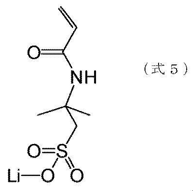
- Example 1 A polymer was synthesized using the monomer of (Formula 5) as the monomer A. Also, the polymer was used to coat a negative electrode active material. Graphite was used as the negative electrode active material.
- Example 2 A single negative electrode was prepared and the irreversible capacity was measured. The irreversible capacity was 23 mAh g -1 . Next, a small battery was made and the direct current resistance was measured. The direct current resistance was 11.0 ⁇ .
- Example 2 Evaluation was carried out in the same manner as in Example 1 except that the polymer amount was 0.1 wt% in Example 1. The irreversible capacity was 24 mAh g ⁇ 1 and the direct current resistance was 11.2 ⁇ .
- Example 3 Evaluation was carried out in the same manner as in Example 1 except that the amount of polymer was changed to 1.0 wt% in Example 1. The irreversible capacity was 23 mAh g ⁇ 1 and the direct current resistance was 11.5 ⁇ .
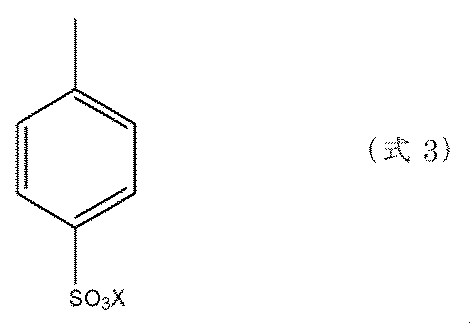
- Example 4 A polymer was synthesized using a monomer using monomer (Formula 3) as monomer A and sodium styrene sulfonate as monomer B. The molar ratio of monomer A to monomer B was 75:25. The negative electrode active material was coated in the same manner as in Example 1 to evaluate the characteristics. The irreversible capacity was 21 mAh g ⁇ 1 and the direct current resistance was 11.1 ⁇ . (Example 5) The procedure of Example 4 was repeated except that the molar ratio of monomers was 50:50. The irreversible capacity was 23 mAh g ⁇ 1 and the direct current resistance was 11.1 ⁇ .
- Example 6 Example 4 was the same as Example 4 except that the molar ratio of monomers was 25:75. The irreversible capacity was 23 mAh g ⁇ 1 and the direct current resistance was 12.0 ⁇ . (Comparative example 1) The same examination as in Example 1 was conducted except that no covering material was added in Example 1. The irreversible capacity was 25 mAh g ⁇ 1 and the direct current resistance was 11.5 ⁇ . (Comparative example 2) The procedure of Example 4 was repeated except that the molar ratio of monomers was changed to 0: 100. The irreversible capacity was 22 mAh g -1 and the direct current resistance was 13.1 ⁇ .
- the polymer A obtained by polymerizing the monomer A had a lower resistance value than the polymers B, C, and D containing the monomer B.
- the polymer containing monomer B is excellent in the reduction of the irreversible capacity.
- the polymer E consisting only of the monomer B had a high direct current resistance as compared with the polymer containing the monomer A. From these results, the ratio x, y of the monomer A and the monomer B is 0 ⁇ x / (x + y) ⁇ 1, preferably 0.25 ⁇ x / (x + y) ⁇ 1, more preferably 0.4 ⁇ x It was confirmed that / (x + y) ⁇ 1.
Landscapes
- Chemical & Material Sciences (AREA)
- Chemical Kinetics & Catalysis (AREA)
- Electrochemistry (AREA)
- General Chemical & Material Sciences (AREA)
- Engineering & Computer Science (AREA)
- Materials Engineering (AREA)
- Manufacturing & Machinery (AREA)
- Battery Electrode And Active Subsutance (AREA)
- Secondary Cells (AREA)
Abstract
Description


図1は、本発明の一実施形態に係る電池の内部構造を模式的に表す図である。図1に示す本発明の一実施形態に係る電池1は、正極10、セパレータ11、負極12、電池容器(即ち電池缶)13、正極集電タブ14、負極集電タブ15、内蓋16、内圧開放弁17、ガスケット18、正温度係数(Positive temperature coefficient;PTC)抵抗素子19、及び電池蓋20、軸心21から構成される。電池蓋20は、内蓋16、内圧開放弁17、ガスケット18、及びPTC抵抗素子19からなる一体化部品である。また、軸心21には、正極10、セパレータ11及び負極12が捲回されている。
正極10は、正極活物質、導電剤、バインダ、及び集電体から構成される。正極活物質を例示すると、LiCoO2、LiNiO2、及びLiMn2O4が代表例である。他に、LiMnO3、LiMn2O3、LiMnO2、Li4Mn5O12、LiMn2-xMxO2(ただし、M=Co、Ni、Fe、Cr、Zn、Tiからなる群から選ばれる少なくとも1種、x=0.01~0.2)、Li2Mn3MO8(ただし、M=Fe、Co、Ni、Cu、Znからなる群から選ばれる少なくとも1種)、Li1-xAxMn2O4(ただし、A=Mg、B、Al、Fe、Co、Ni、Cr、Zn、Caからなる群から選ばれる少なくとも1種、x=0.01~0.1)、LiNi1-xMxO2(ただし、M=Co、Fe、Gaからなる群から選ばれる少なくとも1種、x=0.01~0.2)、LiFeO2、Fe2(SO4)3、LiCo1-xMxO2(ただし、M=Ni、Fe、Mnからなる群から選ばれる少なくとも1種、x=0.01~0.2)、LiNi1-xMxO2(ただし、M=Mn、Fe、Co、Al、Ga、Ca、Mgからなる群から選ばれる少なくとも1種、x=0.01~0.2)、Fe(MoO4)3、FeF3、LiFePO4、及びLiMnPO4等を列挙することができる。
負極は、負極活物質とバインダおよび集電体からなる。負極活物質としては、天然黒鉛,石油コークスや石炭ピッチコークス等から得られる易黒鉛化材料を2500℃以上の高温で熱処理したもの,メソフェーズカーボン或いは非晶質炭素,炭素繊維,リチウムと合金化する金属,あるいは炭素粒子表面に金属を担持した材料が用いられる。例えばリチウム,銀,アルミニウム,スズ,ケイ素,インジウム,ガリウム,マグネシウムより選ばれた金属あるいは合金である。また,該金属または該金属の酸化物を負極活物質として利用できる。さらに、チタン酸リチウムを用いることもできる。

上記の方法で作製した正極10及び負極12の間にセパレータ11を挿入し、正極10及び負極12の短絡を防止する。セパレータ11には、ポリエチレン、ポリプロピレン等からなるポリオレフィン系高分子シート、又はポリオレフィン系高分子と4フッ化ポリエチレンを代表とするフッ素系高分子シートを溶着させた2層構造等を使用することが可能である。電池温度が高くなったときにセパレータ11が収縮しないように、セパレータ11の表面にセラミックス及びバインダの混合物を薄層状に形成してもよい。これらのセパレータ11は、電池の充放電時にリチウムイオンを透過させる必要があるため、一般に細孔径が0.01~10μm、気孔率が20~90%であれば、リチウムイオン電池に使用可能である。
本発明の一実施形態で使用可能な電解液の代表例として、エチレンカーボネートにジメチルカーボネート、ジエチルカーボネート、又はエチルメチルカーボネート等を混合した溶媒に、電解質として六フッ化リン酸リチウム(LiPF6)、又はホウフッ化リチウム(LiBF4)を溶解させた溶液がある。本発明は、溶媒や電解質の種類、溶媒の混合比に制限されることなく、他の電解液も利用可能である。
<ポリマーの合成方法>
反応容器にモノマーと、反応溶媒として水を加えた。さらに、その溶液に重合開始剤としてAIBNを加えた。重合開始剤の濃度はモノマーの総量に対し4wt %になるように加えた。その後、反応溶液を60℃、3 h加熱することでポリマーを合成した。
<正極の作製方法>
正極活物質、導電剤(SP270:日本黒鉛社製黒鉛)、ポリフッ化ビニリデンバインダーを八五:10:10重量%の割合で混合し、N-メチル-2-ピロリ丼に投入混合して、スラリー状の溶液を策製した。該スラリーを厚さ20μmのアルミニウム箔にドクターブレード法で塗布し、乾燥した。合剤塗布量は、200g/m2 であった。その後、プレスして正極を作製した。
<負極の作製方法>
グラファイトにポリフッ化ビニリデンを95:5の重量%の比率で混合し、更にN-メチル-2-ピロリドンに投入混合して、スラリー状の溶液を作製した。該スラリーを厚さ10 μmの銅箔にドクターブレード法で塗布し、乾燥した。合剤かさ密度が1.5 g / cm3になるようにプレスして負極を作製した。
<負極単極の評価方法>
作製した負極を、直径15 mmの円形に打ち抜いて電極を準備した。評価セルは、負極と対極としてLi金属を用い、負極とLi金属の間にセパレータを挿入して、そこに電解液を加えることで構成した。評価セルの充電は、予め設定した下限電圧まで電流密度0.72 mA /cm2で充電した。放電は、予め設定した上限電圧まで、電流密度0.72 mA / cm2で放電した。下限電圧は0.01 V、上限電圧は1.5 Vであった。不可逆容量は、充電容量と放電容量の差分から求めた。
<直流抵抗の評価方法>
正極および負極を直径15 mmの円形に打ち抜いて電極を準備した。小型電池は、正極および負極間にセパレータを挿入して、そこに電解液を加えることで構成した。小型電池の充電は、予め設定した上限電圧まで電流密度0.72 mA /cm2で充電した。放電は、予め設定した下限電圧まで、電流密度0.72 mA / cm2で放電した。上限電圧は4.2 V、下限電圧は3.0 Vであった。1サイクル目に得られた放電容量を、電池の初期容量とした。その後、初期容量の50%まで充電して直流抵抗を測定した。
(実施例1)
モノマーAとして、(式5)のモノマーを使用してポリマーを合成した。また、前記ポリマーを使用して、負極活物質を被覆した。負極活物質には、グラファイトを用いた。
(実施例2)
実施例1において、ポリマー量を0.1 wt%にする以外は実施例1と同様に評価した。不可逆容量は24 mAhg-1であり、直流抵抗は11.2 Ωであった。
(実施例3)
実施例1において、ポリマー量を1.0 wt%にする以外は実施例1と同様に評価した。不可逆容量は23 mAhg-1であり、直流抵抗は11.5 Ωであった。
(実施例4)
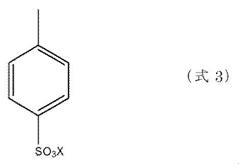
モノマーAとして(式3)のモノマーを、モノマーBとしてスチレンスルホン酸ナトリウムを使用しポリマーを使用してポリマーを合成した。モノマーAとモノマーBのmol比は75:25とした。実施例1と同様に負極活物質を被覆して特性評価をした。不可逆容量は21 mAhg-1であり、直流抵抗は11.1 Ωであった。
(実施例5)
実施例4において、モノマーのmol比を50:50にすること以外は実施例4と同様にした。不可逆容量は23 mAhg-1であり、直流抵抗は11.1 Ωであった。
(実施例6)
実施例4において、モノマーのmol比を25:75にすること以外は実施例4と同様にした。不可逆容量は23 mAhg-1であり、直流抵抗は12.0 Ωであった。
(比較例1)
実施例1において、被覆材を加えないこと以外は実施例1と同様に検討した。不可逆容量は25 mAhg-1であり、直流抵抗は11.5 Ωであった。
(比較例2)
実施例4において、モノマーのmol比を0:100にすること以外は実施例4と同様にした。不可逆容量は22 mAhg-1であり、直流抵抗は13.1 Ωであった。

10 正極
11 セパレータ
12 負極
13 電池容器
14 正極集電タブ
15 負極集電タブ
16 内蓋
17 内圧開放弁
18 ガスケット
19 正温度係数抵抗素子
20 電池蓋
21 軸心
Claims (7)
- (式1)で表わされるリチウムイオン二次電池用負極活物質被覆材。
((式1)のAはアミド基(-NHCO-)とスルホ基(-SO3X;X:アルカリ金属、H)を有する官能基である。Bは極性官能基を有する官能基である。(式1)のR1からR6は、炭素数1~10の炭化水素基または、Hである。(式1)のx、yは、共重合の組成比であり、0<x/(x+y)≦1である。)
- 請求項1において、
(式1)中のAは(式2)で表わされるリチウムイオン二次電池用負極活物質被覆材。
((式2)のR7およびR8は、炭素数1~10のアルキル基またはHである。(式2)のR9は、メチレン基(-(-CH2-)n-)であり、nは0以上10以下である。 (式2)のXは、アルカリ金属またはHである。)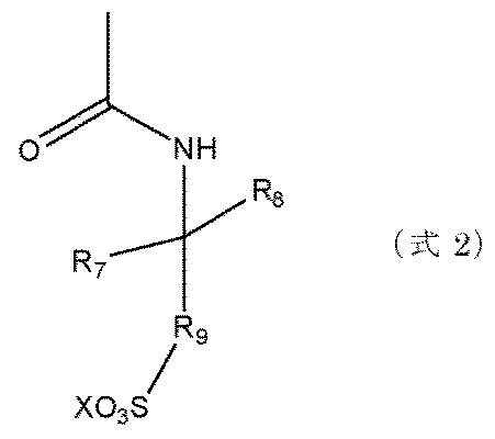
- 請求項1または請求項2において、
前記共重合の組成比が0.4≦x/(x+y) ≦1であるリチウムイオン二次電池用負極活物質被覆材。 - 請求項1ないし請求項3のいずれかにおいて、
(式1)中のBは、水酸基、カルボキシル基、スルホ基、アミノ基を含む官能基であるリチウムイオン二次電池用負極活物質被覆材。 - 請求項1ないし請求項4のいずれかにおいて、
(式1)中のBは、(式3)で表わされるリチウムイオン二次電池用負極活物質被覆材。
- 負極活物質の表面に請求項1ないし請求項5に記載のリチウムイオン二次電池用負極活物質被覆材を有するリチウムイオン電池用負極材料
- 請求項6に記載の負極活物質を有するリチウムイオン二次電池。
Priority Applications (5)
| Application Number | Priority Date | Filing Date | Title |
|---|---|---|---|
| PCT/JP2013/052309 WO2014118963A1 (ja) | 2013-02-01 | 2013-02-01 | リチウムイオン二次電池用負極材料 |
| JP2014559454A JP6023222B2 (ja) | 2013-02-01 | 2013-02-01 | リチウムイオン二次電池用負極材料 |
| US14/762,619 US20150372272A1 (en) | 2013-02-01 | 2013-02-01 | Negative electrode material for lithium ion secondary batteries |
| CN201380071647.7A CN104956526B (zh) | 2013-02-01 | 2013-02-01 | 锂离子二次电池用负极材料 |
| TW102147654A TWI548137B (zh) | 2013-02-01 | 2013-12-20 | Lithium ion secondary battery anode material |
Applications Claiming Priority (1)
| Application Number | Priority Date | Filing Date | Title |
|---|---|---|---|
| PCT/JP2013/052309 WO2014118963A1 (ja) | 2013-02-01 | 2013-02-01 | リチウムイオン二次電池用負極材料 |
Publications (1)
| Publication Number | Publication Date |
|---|---|
| WO2014118963A1 true WO2014118963A1 (ja) | 2014-08-07 |
Family
ID=51261707
Family Applications (1)
| Application Number | Title | Priority Date | Filing Date |
|---|---|---|---|
| PCT/JP2013/052309 Ceased WO2014118963A1 (ja) | 2013-02-01 | 2013-02-01 | リチウムイオン二次電池用負極材料 |
Country Status (5)
| Country | Link |
|---|---|
| US (1) | US20150372272A1 (ja) |
| JP (1) | JP6023222B2 (ja) |
| CN (1) | CN104956526B (ja) |
| TW (1) | TWI548137B (ja) |
| WO (1) | WO2014118963A1 (ja) |
Cited By (1)
| Publication number | Priority date | Publication date | Assignee | Title |
|---|---|---|---|---|
| JP2017054703A (ja) * | 2015-09-09 | 2017-03-16 | 三洋化成工業株式会社 | 非水系二次電池活物質被覆用樹脂、非水系二次電池用被覆活物質及び非水系二次電池用被覆活物質の製造方法 |
Citations (5)
| Publication number | Priority date | Publication date | Assignee | Title |
|---|---|---|---|---|
| WO2007072948A1 (ja) * | 2005-12-22 | 2007-06-28 | Jsr Corporation | 二次電池電極用バインダー組成物、二次電池電極用スラリー、及び二次電池電極 |
| WO2007088979A1 (ja) * | 2006-02-02 | 2007-08-09 | Jsr Corporation | 重合体組成物、二次電池電極用ペースト、及び二次電池電極 |
| WO2011024789A1 (ja) * | 2009-08-24 | 2011-03-03 | Jsr株式会社 | 電極形成用組成物、電極形成用スラリー、電極および電気化学デバイス |
| JP2012204303A (ja) * | 2011-03-28 | 2012-10-22 | Nippon Zeon Co Ltd | 二次電池用電極、二次電池電極用バインダー、製造方法及び二次電池 |
| JP2013012357A (ja) * | 2011-06-28 | 2013-01-17 | Nippon Zeon Co Ltd | 二次電池用負極、二次電池、負極用スラリー組成物及び二次電池用負極の製造方法 |
Family Cites Families (2)
| Publication number | Priority date | Publication date | Assignee | Title |
|---|---|---|---|---|
| JP4265191B2 (ja) * | 2002-09-27 | 2009-05-20 | 住友ベークライト株式会社 | リチウムイオン伝導性全固体型電解質およびリチウムイオン伝導性ゲル状電解質 |
| JP2015118908A (ja) * | 2013-11-14 | 2015-06-25 | Jsr株式会社 | 蓄電デバイス用バインダー組成物、蓄電デバイス用スラリー、蓄電デバイス電極、セパレーターおよび蓄電デバイス |
-
2013
- 2013-02-01 CN CN201380071647.7A patent/CN104956526B/zh not_active Expired - Fee Related
- 2013-02-01 WO PCT/JP2013/052309 patent/WO2014118963A1/ja not_active Ceased
- 2013-02-01 US US14/762,619 patent/US20150372272A1/en not_active Abandoned
- 2013-02-01 JP JP2014559454A patent/JP6023222B2/ja not_active Expired - Fee Related
- 2013-12-20 TW TW102147654A patent/TWI548137B/zh active
Patent Citations (5)
| Publication number | Priority date | Publication date | Assignee | Title |
|---|---|---|---|---|
| WO2007072948A1 (ja) * | 2005-12-22 | 2007-06-28 | Jsr Corporation | 二次電池電極用バインダー組成物、二次電池電極用スラリー、及び二次電池電極 |
| WO2007088979A1 (ja) * | 2006-02-02 | 2007-08-09 | Jsr Corporation | 重合体組成物、二次電池電極用ペースト、及び二次電池電極 |
| WO2011024789A1 (ja) * | 2009-08-24 | 2011-03-03 | Jsr株式会社 | 電極形成用組成物、電極形成用スラリー、電極および電気化学デバイス |
| JP2012204303A (ja) * | 2011-03-28 | 2012-10-22 | Nippon Zeon Co Ltd | 二次電池用電極、二次電池電極用バインダー、製造方法及び二次電池 |
| JP2013012357A (ja) * | 2011-06-28 | 2013-01-17 | Nippon Zeon Co Ltd | 二次電池用負極、二次電池、負極用スラリー組成物及び二次電池用負極の製造方法 |
Cited By (1)
| Publication number | Priority date | Publication date | Assignee | Title |
|---|---|---|---|---|
| JP2017054703A (ja) * | 2015-09-09 | 2017-03-16 | 三洋化成工業株式会社 | 非水系二次電池活物質被覆用樹脂、非水系二次電池用被覆活物質及び非水系二次電池用被覆活物質の製造方法 |
Also Published As
| Publication number | Publication date |
|---|---|
| US20150372272A1 (en) | 2015-12-24 |
| TWI548137B (zh) | 2016-09-01 |
| CN104956526B (zh) | 2017-03-08 |
| JP6023222B2 (ja) | 2016-11-09 |
| CN104956526A (zh) | 2015-09-30 |
| TW201448330A (zh) | 2014-12-16 |
| JPWO2014118963A1 (ja) | 2017-01-26 |
Similar Documents
| Publication | Publication Date | Title |
|---|---|---|
| JP6110951B2 (ja) | リチウムイオン二次電池用負極材料、及びそれを用いたリチウムイオン二次電池用負極、リチウムイオン二次電池、電池システム | |
| KR102230038B1 (ko) | 리튬 이차 전지 | |
| WO2014136794A1 (ja) | リチウム二次電池 | |
| US9831526B2 (en) | Lithium secondary battery | |
| JP7199157B2 (ja) | ヨウ化リチウムを含む電解液、及びそれを用いたリチウムイオン電池 | |
| JP6258180B2 (ja) | リチウム二次電池用電解液の添加剤及びそれを用いたリチウム二次電池用電解液、リチウム二次電池 | |
| US20200112060A1 (en) | Non-aqueous electrolyte for lithium ion secondary battery and lithium ion secondary battery using same | |
| JP6992362B2 (ja) | リチウムイオン二次電池 | |
| JP6812827B2 (ja) | 非水電解液およびそれを用いた非水電解液電池 | |
| WO2015029248A1 (ja) | 負極活物質被覆材並びにこれを用いた負極材料、負極、リチウムイオン二次電池及び電池システム並びにモノマー及びその合成方法 | |
| JP2017117686A (ja) | リチウムイオン二次電池 | |
| JP2015204178A (ja) | リチウムイオン二次電池用負極、リチウムイオン二次電池およびそれらの製造方法 | |
| JP2018133284A (ja) | 非水電解液およびそれを用いた非水電解液電池 | |
| WO2015037115A1 (ja) | リチウムイオン二次電池用負極材料 | |
| JP2015159050A (ja) | Li電池用材料 | |
| JP2011040333A (ja) | 非水電解液二次電池 | |
| JP2013239356A (ja) | リチウムイオン二次電池用負極保護剤、リチウムイオン二次電池用負極材、リチウムイオン二次電池用負極、リチウムイオン二次電池およびそれらの製造方法 | |
| JP2018133335A (ja) | 非水電解液電池 | |
| CN111052486A (zh) | 非水电解质二次电池 | |
| JP6023222B2 (ja) | リチウムイオン二次電池用負極材料 | |
| JP2018133285A (ja) | 非水電解液およびそれを用いた非水電解液電池 | |
| JP6222389B1 (ja) | 非水電解液およびそれを用いた非水電解液電池 | |
| WO2015015598A1 (ja) | リチウムイオン二次電池負極活物質用被覆材、前記被覆材で被覆されたリチウムイオン二次電池負極活物質、および、前記負極活物質を負極に用いたリチウムイオン二次電池 | |
| WO2015118676A1 (ja) | Li電池用材料 | |
| WO2015118675A1 (ja) | リチウムイオン二次電池用負極材料 |
Legal Events
| Date | Code | Title | Description |
|---|---|---|---|
| 121 | Ep: the epo has been informed by wipo that ep was designated in this application |
Ref document number: 13873863 Country of ref document: EP Kind code of ref document: A1 |
|
| ENP | Entry into the national phase |
Ref document number: 2014559454 Country of ref document: JP Kind code of ref document: A |
|
| WWE | Wipo information: entry into national phase |
Ref document number: 14762619 Country of ref document: US |
|
| NENP | Non-entry into the national phase |
Ref country code: DE |
|
| 122 | Ep: pct application non-entry in european phase |
Ref document number: 13873863 Country of ref document: EP Kind code of ref document: A1 |