WO2014115757A1 - 膜材の接合方法 - Google Patents
膜材の接合方法 Download PDFInfo
- Publication number
- WO2014115757A1 WO2014115757A1 PCT/JP2014/051236 JP2014051236W WO2014115757A1 WO 2014115757 A1 WO2014115757 A1 WO 2014115757A1 JP 2014051236 W JP2014051236 W JP 2014051236W WO 2014115757 A1 WO2014115757 A1 WO 2014115757A1
- Authority
- WO
- WIPO (PCT)
- Prior art keywords
- membrane materials
- membrane
- materials
- joining
- pair
- Prior art date
- Legal status (The legal status is an assumption and is not a legal conclusion. Google has not performed a legal analysis and makes no representation as to the accuracy of the status listed.)
- Ceased
Links
Images

Classifications
-
- E—FIXED CONSTRUCTIONS
- E04—BUILDING
- E04H—BUILDINGS OR LIKE STRUCTURES FOR PARTICULAR PURPOSES; SWIMMING OR SPLASH BATHS OR POOLS; MASTS; FENCING; TENTS OR CANOPIES, IN GENERAL
- E04H15/00—Tents or canopies, in general
- E04H15/32—Parts, components, construction details, accessories, interior equipment, specially adapted for tents, e.g. guy-line equipment, skirts, thresholds
- E04H15/54—Covers of tents or canopies
-
- E—FIXED CONSTRUCTIONS
- E04—BUILDING
- E04H—BUILDINGS OR LIKE STRUCTURES FOR PARTICULAR PURPOSES; SWIMMING OR SPLASH BATHS OR POOLS; MASTS; FENCING; TENTS OR CANOPIES, IN GENERAL
- E04H15/00—Tents or canopies, in general
- E04H15/32—Parts, components, construction details, accessories, interior equipment, specially adapted for tents, e.g. guy-line equipment, skirts, thresholds
- E04H15/64—Tent or canopy cover fastenings
Definitions
- the present invention relates to a method of joining adjacent side end portions of a membrane material from the inside of the structure when a membrane material such as a tent is stretched on, for example, a roof portion or a side wall portion of the structure.
- the joint film is arranged outside the adjacent side ends of the structure and the film material in order to avoid exposing the string tied through the eyelet to the external environment. Cannot be joined from inside the body. That is, since work from the outside of the membrane material is required, work from the roof occurs in the case of the roof. Moreover, in the case of the side wall part, it was necessary to work by installing a temporary scaffold outside the membrane material.
- the joint membrane is made of the framework structure and the membrane material. It arrange
- the problem to be solved by the present invention is that, in the case of the method shown in FIG. 2, adjacent side edges of the film material cannot be joined from the inside of the structure.
- the present invention was made for the purpose of providing a method capable of joining adjacent side end portions of a film material from the inside of the structure.
- the joining method of the membrane material of the present invention is as follows: A method of joining adjacent side edges of a plurality of film materials stretched on a structure, First, each side edge of the two adjacent membrane materials is sandwiched between flat plates from the front and back sides, and a pair of membrane material fixing portions is formed by tightening these flat plates, Next, screw rods are passed through the two membrane materials and the flat plate sandwiching these membrane materials at positions different from the tightening positions so that the side end portions of the two membrane materials face the inner surface of the structure.
- the main feature is that the screw rod is replaced with a main joining bolt to join the pair of membrane material fixing portions.
- the side ends of both membrane materials are directed toward the inner surface of the structure, and the screw rods and nuts are used to
- the flat plates are brought into close contact with each other, tension is introduced into the two membrane materials, and then the screw rod is replaced with the main joining bolt. Therefore, the membrane material can be joined from the inside of the structure.
- the membrane material can be joined from the inside of the structure, and it is not necessary to work on the roof or to provide a temporary scaffold on the outside of the structure. Adjacent side edges can be joined together.
- (A)-(f) is a figure explaining the method of joining the adjacent edge parts of the film
- the present invention aims to join each side end of both membrane materials adjacent to each other from the inside of the structure. After sandwiching each side end from the front and back sides with a flat plate, the side end of the structure is This was realized by bringing the flat plates of the two membrane materials into close contact with each other with the screw rod and nut so that they face the inner surface, introducing tension into the two membrane materials, and then replacing the screw rod with the main joining bolt.
- the present invention is a method of joining adjacent side end portions 11a and 12a of membrane materials 11 and 12 stretched on, for example, a roof portion of a structure.
- description will be given step by step with reference to FIG.
- the thicknesses t1a and t2a of the adjacent side end portions 11a and 12a of the film materials 11 and 12 are set to be thicker than the thicknesses t1b and t2b of the other portions 11b and 12b.
- a long member 13 such as a rope or rubber is inserted into a cylindrical interior formed by folding the adjacent side end portions 11 a and 12 b of both membrane materials 11 and 12 toward the center portion.
- the thicknesses t1a and t2a of the side end portions 11a and 12a are made thicker than the thicknesses t1b and t2b of the other portions 11b and 12b (see FIG. 1A).
- the membrane material fixing hardware 14 is difficult to be detached from the side end portions 11a and 12b of the membrane materials 11 and 12, it is not limited to the one in which the long member 13 is attached to the side end portions 11a and 12b as shown in FIG. Alternatively, a plurality of side end portions 11a and 12b that are folded back may be used.
- the thickness t1a of each side end portion 11a and 12a adjacent to each of the film materials 11 and 12 is not necessarily limited. It is not necessary to make t2a thicker than the thicknesses t1b and t2b of the other portions 11b and 12b.
- a pair of membrane material fixing portions is formed by attaching a membrane material fixing metal 14 to the center side of the long member 13 inserted in each of the side end portions 11a and 12b (see FIG. 1B).
- the film material fixing hardware 14 is composed of, for example, two flat bolts 14c and nuts 14d sandwiching the film materials 11 and 12 from the front and back sides of a pair of metal flat plates 14a and 14b of a predetermined length such as aluminum. Tighten. Through holes 14e for long screw rods 15a are provided at the three positions on the flat plates 14a and 14b between the tightening positions of the countersunk bolts 14c and the nuts 14d and on both sides of the tightening positions.
- the flat bolt 14c is inserted from the outside of the structure so that the head of the flat bolt 14c does not protrude from the surface of the flat plate 14a located outside. deep.
- the flat plates 14a attached to the side end portions 11a and 12a of the both membrane materials 11 and 12 are arranged so that the side end portions 11a and 12a of the both membrane materials 11 and 12 face the inner surface of the structure.
- the screw rod 15a is passed through the through hole 14e provided in the opposed film material fixing metal 14, and nuts 15b are attached to both sides of the penetrated screw rod 15a (see FIG. 1 (c)).
- the nuts 15b fitted from both ends of the three screw rods 15a are sequentially tightened to bring the flat plates 14a, 14a of the pair of film material fixing portions into close contact with each other, and tension is introduced into the film materials 11, 12. (See FIG. 1 (d)).
- the method of the present invention is not limited to the roof portion, but on the side wall portion.
- the present invention can also be applied to bonding when a film material constituting a tent or the like is stretched.
- the U-shaped hardware 17 is attached to the main joining bolt 16a at an appropriate position and engaged with the cable 18. However, if the U-shaped hardware 17 can be engaged with the cable 18, the U-shaped hardware 17 is used. It is not necessary.
Landscapes
- Engineering & Computer Science (AREA)
- Architecture (AREA)
- Civil Engineering (AREA)
- Structural Engineering (AREA)
- Tents Or Canopies (AREA)
Abstract
膜材の隣り合う側端部同士を構造体の内側から接合する。 複数の膜材11,12の隣接する各側端部11a,12aの厚さt1a,t2aを他の部分11b,12bよりも厚くする。前記側端部11a,12aよりも中央側を平板14a,14bで挟んでねじ締めし、一対の膜材固定部を形成する。両膜材11,12の側端部11a,12aを構造体の内面方向に向かせる。前記ねじ締め位置と異なる位置で、両膜材11,12とこれら膜材11,12を挟み込んだ平板14a,14bに貫通させたねじ棒15aをナット15bで締め込み、一対の膜材固定部の平板同士を密着させて両膜材11,12に張力を導入する。その後、ねじ棒15aを本接合用ボルト16aに付け替えて一対の膜材固定部同士を接合する。
Description
本発明は、構造体の例えば屋根部や側壁部にテント等の膜材を張る場合に、膜材の隣り合う側端部同士を構造体の内側から接合する方法に関するものである。
例えばトラス構造からなる構造体の屋根部や側壁部にテントを張る際、屋根部の面積が広い場合は1枚のテントで屋根部を覆うことができないので、複数枚の膜材を用いてテントを張ることになる。
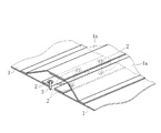
このように複数枚の膜材を用いてテントを張る場合、膜材の隣り合う側端部同士を接合する必要がある。この隣り合う側端部同士の接合は、例えば図2に示すように、膜材1の隣り合う側端部に鳩目2をジグザグに設け、これら鳩目2に紐3を通して結んだ後(レイシング法)、膜材1の隣り合う側端部から二股に分岐させた継手膜1aの先端同士を融着することで行っていた(特許文献1の従来技術参照)。
しかしながら、上記接合方法では、鳩目に通して結んだ紐を外部環境に曝すことを避けるために継手膜を構造体及び膜材の隣り合う側端部同士の外側に配置することになるので、構造体の内側から接合することができない。つまり、膜材の外側からの作業が必要となるため、屋根部の場合には屋根上からの作業が発生する。また、側壁部の場合には、膜材の外側に仮設足場を設置して作業する必要があった。
膜材の隣り合う側端部同士の接合を図2に示した方法で行う場合は、鳩目に通して結んだ紐を外部環境に曝すことを避けるため、継手膜を骨組構造体及び膜材の隣り合う側端部同士の外側に配置することになる。
本発明が解決しようとする問題点は、図2に示した方法の場合、膜材の隣り合う側端部同士を構造体の内側から接合することができないという点である。
本発明は、膜材の隣り合う側端部同士を、構造体の内側から接合できる方法を提供することを目的としてなされたものである。
本発明の膜材の接合方法は、
構造体に張る複数の膜材の、隣接する側端部同士を接合する方法であって、
先ず、前記隣接する両膜材の各側端部を表裏面側から平板で挟み、これら平板を締め付けることによって一対の膜材固定部を形成し、
次に、前記両膜材の側端部が前記構造体の内面方向に向くようにして、前記締め付け位置と異なる位置で、前記両膜材とこれら膜材を挟んだ前記平板にねじ棒を貫通させた後、これらねじ棒に嵌合するナットを締め込んで前記一対の膜材固定部の前記平板同士を密着させることによって前記両膜材に張力を導入し、
その後、前記ねじ棒を本接合用ボルトに付け替えて前記一対の膜材固定部同士を接合することを最も主要な特徴としている。
構造体に張る複数の膜材の、隣接する側端部同士を接合する方法であって、
先ず、前記隣接する両膜材の各側端部を表裏面側から平板で挟み、これら平板を締め付けることによって一対の膜材固定部を形成し、
次に、前記両膜材の側端部が前記構造体の内面方向に向くようにして、前記締め付け位置と異なる位置で、前記両膜材とこれら膜材を挟んだ前記平板にねじ棒を貫通させた後、これらねじ棒に嵌合するナットを締め込んで前記一対の膜材固定部の前記平板同士を密着させることによって前記両膜材に張力を導入し、
その後、前記ねじ棒を本接合用ボルトに付け替えて前記一対の膜材固定部同士を接合することを最も主要な特徴としている。
本発明では、隣接する両膜材の各側端部の表裏面を平板で挟んだ後、両膜材の側端部を構造体の内面方向に向かせてねじ棒とナットで両膜材の平板同士を密着させて前記両膜材に張力を導入し、その後、ねじ棒を本接合用ボルトに付け替える。従って、構造体の内側から膜材の接合が可能になる。
本発明では、構造体の内側から膜材の接合が可能になり、屋根上での作業や、構造体の外側に仮設足場を設ける必要がなくなるので、短期間及び低コストで容易に膜体の隣り合う側端部同士を接合することができる。
本発明は、隣接する両膜材の各側端部同士を構造体の内側から接合するという目的を、前記各側端部を表裏面側から平板で挟んだ後、側端部が構造体の内面方向に向くようにしてねじ棒とナットで両膜材の平板同士を密着させて前記両膜材に張力を導入し、その後、ねじ棒を本接合用ボルトに付け替えることで実現した。
本発明は、構造体の例えば屋根部に張る膜材11,12の、隣接する各側端部11a,12a同士を接合する方法である。以下、図1を用いて順を追って説明する。
(事前作業)
前記両膜材11,12の隣接する各側端部11a,12aの厚さt1a,t2aが他の部分11b,12bの厚さt1b,t2bよりも厚くなるようにしておく。
前記両膜材11,12の隣接する各側端部11a,12aの厚さt1a,t2aが他の部分11b,12bの厚さt1b,t2bよりも厚くなるようにしておく。
図1に示す例では、両膜材11,12の隣接する各側端部11a,12bを中央部側に折り返して形成した筒状の内部にロープやゴム等の長尺部材13を挿入することで、各側端部11a,12aの厚さt1a,t2aを他の部分11b,12bの厚さt1b,t2bよりも厚くしている(図1(a)参照)。
このように両膜材11,12の隣接する各側端部11a,12aの厚さt1a,t2aを他の部分11b,12bの厚さt1b,t2bよりも厚くすることで、これら側端部11a,12aよりも中央側に取付ける膜材固定金物14が、側端部11a,12aから外れ難くなる。
従って、膜材固定金物14が膜材11,12の側端部11a,12bから外れ難いものであれば、図1のように側端部11a,12bに前記長尺部材13を取付けるものに限らず、側端部11a,12bを複数回折り返したもの等でも良い。
また、取付けた膜材固定金物14が膜材11,12の側端部11a,12bから外れ難い場合は、必ずしも両膜材11,12の隣接する各側端部11a,12aの厚さt1a,t2aを他の部分11b,12bの厚さt1b,t2bよりも厚くしなくてもよい。
(接合作業)
先ず、前記各側端部11a,12bに挿入した前記長尺部材13よりも中央側に膜材固定金物14を取付けて一対の膜材固定部を形成する(図1(b)参照)。
先ず、前記各側端部11a,12bに挿入した前記長尺部材13よりも中央側に膜材固定金物14を取付けて一対の膜材固定部を形成する(図1(b)参照)。
この膜材固定金物14は、例えば、対をなす所定長さのアルミニウム等の金属製の平板14a,14bで膜材11,12を表裏面側から挟んで2個の皿ボルト14c及びナット14dで締付けるものである。平板14a,14bの、皿ボルト14cとナット14dによる締付け位置の間、及び締付け位置の両側の3箇所には、長尺のねじ棒15aの貫通孔14eを設けている。
前記平板14a,14bで膜材11,12を挟んで締付ける際、構造体の外側から皿ボルト14cを挿入し、外側に位置する平板14aの表面から皿ボルト14cの頭部が突出しないようにしておく。
次に、前記両膜材11,12の側端部11a,12aが前記構造体の内面方向に向くようにして両膜材11,12の側端部11a,12aに取付けた平板14a同士を相対させる。この状態で、相対させた膜材固定金物14に設けた前記貫通孔14eにねじ棒15aを貫通し、貫通させたねじ棒15aの両側にナット15bを取付ける(図1(c)参照)。
前記3本のねじ棒15aの両端から嵌合するナット15bを順次締め込んで前記一対の膜材固定部の前記平板14a,14a同士を密着させ、前記両膜材11,12に張力を導入する(図1(d)参照)。
その後、ナット15bを締め込んだ前記3本のねじ棒15aを、順次、本接合用ボルト16aに付け替えて、前記一対の膜材固定部同士を接合する(図1(e)参照)。その際、適宜の位置の本接合用ボルト16aにはU字金物17を取付けて膜材11,12を張るためのケーブル18に係合し、構造物に取付ける(図1(f))。なお、16bは本接合用ボルト16aに嵌合するナットである。
本発明は、前記の例に限るものではなく、各請求項に記載の技術的思想の範疇であれば、適宜実施の形態を変更しても良いことは言うまでもない。
例えば、上記の例では、構造体の屋根部に張るテントを構成する膜材の隣り合う側端部同士を接合する場合について説明したが、本発明方法は、屋根部に限らず、側壁部にテント等を構成する膜材を張る際の接合にも適用できることは言うまでもない。
また、上記の例では、適宜の位置の本接合用ボルト16aにU字金物17を取付けてケーブル18に係合しているが、ケーブル18に係合できるものであれば、U字金物17でなくても良い。
11 膜材
11a 側端部
11b 他の部分
12 膜材
12a 側端部
12b 他の部分
14 膜材固定金物
14a,14b 平板
14c 皿ボルト
14d ナット
14e 貫通孔
15a ねじ棒
15b ナット
16a 本接合用ボルト
16b ナット
17 U字金物
18 張設用ケーブル
11a 側端部
11b 他の部分
12 膜材
12a 側端部
12b 他の部分
14 膜材固定金物
14a,14b 平板
14c 皿ボルト
14d ナット
14e 貫通孔
15a ねじ棒
15b ナット
16a 本接合用ボルト
16b ナット
17 U字金物
18 張設用ケーブル
Claims (3)
- 構造体に張る複数の膜材の、隣接する側端部同士を接合する方法であって、
先ず、前記隣接する両膜材の各側端部を表裏面側から平板で挟み、これら平板を締め付けることによって一対の膜材固定部を形成し、
次に、前記両膜材の側端部が前記構造体の内面方向に向くようにして、前記締め付け位置と異なる位置で、前記両膜材とこれら膜材を挟んだ前記平板にねじ棒を貫通させた後、これらねじ棒に嵌合するナットを締め込んで前記一対の膜材固定部の前記平板同士を密着させることによって前記両膜材に張力を導入し、
その後、前記ねじ棒を本接合用ボルトに付け替えて前記一対の膜材固定部同士を接合することを特徴とする膜材の接合方法。 - 前記隣接する両膜材の各側端部の厚さが他の部分の厚さよりも厚いことを特徴とする請求の範囲第1項に記載の膜材の接合方法。
- 前記ねじ棒を本接合用ボルトに付け替える際、適宜の本接合用ボルトにU字金物を取り付けて両膜材を張るためのケーブルに係合することを特徴とする請求の範囲第1項又は第2項に記載の膜材の接合方法。
Applications Claiming Priority (2)
| Application Number | Priority Date | Filing Date | Title |
|---|---|---|---|
| JP2013010432A JP6099994B2 (ja) | 2013-01-23 | 2013-01-23 | 膜材の接合方法 |
| JP2013-010432 | 2013-01-23 |
Publications (1)
| Publication Number | Publication Date |
|---|---|
| WO2014115757A1 true WO2014115757A1 (ja) | 2014-07-31 |
Family
ID=51227548
Family Applications (1)
| Application Number | Title | Priority Date | Filing Date |
|---|---|---|---|
| PCT/JP2014/051236 Ceased WO2014115757A1 (ja) | 2013-01-23 | 2014-01-22 | 膜材の接合方法 |
Country Status (2)
| Country | Link |
|---|---|
| JP (1) | JP6099994B2 (ja) |
| WO (1) | WO2014115757A1 (ja) |
Citations (3)
| Publication number | Priority date | Publication date | Assignee | Title |
|---|---|---|---|---|
| JPS4938527B1 (ja) * | 1968-04-16 | 1974-10-18 | ||
| JPH102132A (ja) * | 1996-06-18 | 1998-01-06 | Takenaka Komuten Co Ltd | 二重膜の同時張設施工方法 |
| JP2002520527A (ja) * | 1998-07-16 | 2002-07-09 | エーベル,ルネ | 膨張可能なカバー部材及びこれらを支持構造に並置することによって得られるアッセンブリ |
Family Cites Families (2)
| Publication number | Priority date | Publication date | Assignee | Title |
|---|---|---|---|---|
| JPS63130877A (ja) * | 1986-11-21 | 1988-06-03 | 清水建設株式会社 | 張力膜構造 |
| JP2946367B2 (ja) * | 1992-02-03 | 1999-09-06 | 株式会社竹中工務店 | 大面積の2方向曲率膜屋根 |
-
2013
- 2013-01-23 JP JP2013010432A patent/JP6099994B2/ja active Active
-
2014
- 2014-01-22 WO PCT/JP2014/051236 patent/WO2014115757A1/ja not_active Ceased
Patent Citations (3)
| Publication number | Priority date | Publication date | Assignee | Title |
|---|---|---|---|---|
| JPS4938527B1 (ja) * | 1968-04-16 | 1974-10-18 | ||
| JPH102132A (ja) * | 1996-06-18 | 1998-01-06 | Takenaka Komuten Co Ltd | 二重膜の同時張設施工方法 |
| JP2002520527A (ja) * | 1998-07-16 | 2002-07-09 | エーベル,ルネ | 膨張可能なカバー部材及びこれらを支持構造に並置することによって得られるアッセンブリ |
Also Published As
| Publication number | Publication date |
|---|---|
| JP2014141814A (ja) | 2014-08-07 |
| JP6099994B2 (ja) | 2017-03-22 |
Similar Documents
| Publication | Publication Date | Title |
|---|---|---|
| TWI567273B (zh) | An energy dissipation support device with a viewing window | |
| TWI570306B (zh) | A beam bracing device with a viewing window | |
| WO2018113473A1 (zh) | 一种用于钢筋部品化施工的机械连接装置及钢筋连接方法 | |
| TW201531615A (zh) | 具有檢視窗孔的斜撐裝置 | |
| CN103225640B (zh) | 管材用紧固连接配件 | |
| TWI570305B (zh) | A beam support device with a viewing window | |
| JP2011052483A (ja) | 柱継手構造 | |
| WO2014115757A1 (ja) | 膜材の接合方法 | |
| JP6960966B2 (ja) | 部材間の接合構造および接合方法 | |
| US20160123368A1 (en) | Fastener for blind hole | |
| CA2905158A1 (en) | Clamp for temporary structure sheeting and related methods | |
| JP2011012693A (ja) | 挟持用ねじ | |
| JP2008241003A (ja) | 重仮設構造物の継手金具における接合法及び接合確認装置 | |
| JP3201829U (ja) | ブレース | |
| TW201531614A (zh) | 具有檢視窗孔的消能斜撐裝置 | |
| CN106684791B (zh) | 一种电力线路风绳紧固器 | |
| CN115961801A (zh) | 一种门式钢架的主动加固方法 | |
| JP2001107936A (ja) | ナットの固着構造 | |
| KR101811854B1 (ko) | 포스트 텐션 정착구 시스템 | |
| CN105442702B (zh) | 一种张拉整体结构使用的多层螺栓球节点 | |
| JP4029342B2 (ja) | 機械式鉄筋継手 | |
| CN116876367B (zh) | 一种大直径uu型钢拉杆张拉工装及方法 | |
| JP3189177B2 (ja) | 構造体用テンション材の緊張方法及び緊張機構並びに緊張用治具 | |
| JP5289351B2 (ja) | 等電位ボンディング金具 | |
| JP2004360886A (ja) | ローラチェーン端末ボルト |
Legal Events
| Date | Code | Title | Description |
|---|---|---|---|
| 121 | Ep: the epo has been informed by wipo that ep was designated in this application |
Ref document number: 14743383 Country of ref document: EP Kind code of ref document: A1 |
|
| NENP | Non-entry into the national phase |
Ref country code: DE |
|
| 122 | Ep: pct application non-entry in european phase |
Ref document number: 14743383 Country of ref document: EP Kind code of ref document: A1 |