WO2014115707A1 - プラズマ生成装置、及び内燃機関 - Google Patents
プラズマ生成装置、及び内燃機関 Download PDFInfo
- Publication number
- WO2014115707A1 WO2014115707A1 PCT/JP2014/051068 JP2014051068W WO2014115707A1 WO 2014115707 A1 WO2014115707 A1 WO 2014115707A1 JP 2014051068 W JP2014051068 W JP 2014051068W WO 2014115707 A1 WO2014115707 A1 WO 2014115707A1
- Authority
- WO
- WIPO (PCT)
- Prior art keywords
- plasma
- electromagnetic wave
- discharge
- plasma generating
- condition
- Prior art date
Links
Images


Classifications
-
- F—MECHANICAL ENGINEERING; LIGHTING; HEATING; WEAPONS; BLASTING
- F02—COMBUSTION ENGINES; HOT-GAS OR COMBUSTION-PRODUCT ENGINE PLANTS
- F02P—IGNITION, OTHER THAN COMPRESSION IGNITION, FOR INTERNAL-COMBUSTION ENGINES; TESTING OF IGNITION TIMING IN COMPRESSION-IGNITION ENGINES
- F02P23/00—Other ignition
- F02P23/04—Other physical ignition means, e.g. using laser rays
- F02P23/045—Other physical ignition means, e.g. using laser rays using electromagnetic microwaves
-
- F—MECHANICAL ENGINEERING; LIGHTING; HEATING; WEAPONS; BLASTING
- F02—COMBUSTION ENGINES; HOT-GAS OR COMBUSTION-PRODUCT ENGINE PLANTS
- F02M—SUPPLYING COMBUSTION ENGINES IN GENERAL WITH COMBUSTIBLE MIXTURES OR CONSTITUENTS THEREOF
- F02M57/00—Fuel-injectors combined or associated with other devices
- F02M57/06—Fuel-injectors combined or associated with other devices the devices being sparking plugs
-
- F—MECHANICAL ENGINEERING; LIGHTING; HEATING; WEAPONS; BLASTING
- F02—COMBUSTION ENGINES; HOT-GAS OR COMBUSTION-PRODUCT ENGINE PLANTS
- F02P—IGNITION, OTHER THAN COMPRESSION IGNITION, FOR INTERNAL-COMBUSTION ENGINES; TESTING OF IGNITION TIMING IN COMPRESSION-IGNITION ENGINES
- F02P3/00—Other installations
- F02P3/01—Electric spark ignition installations without subsequent energy storage, i.e. energy supplied by an electrical oscillator
-
- H—ELECTRICITY
- H05—ELECTRIC TECHNIQUES NOT OTHERWISE PROVIDED FOR
- H05H—PLASMA TECHNIQUE; PRODUCTION OF ACCELERATED ELECTRICALLY-CHARGED PARTICLES OR OF NEUTRONS; PRODUCTION OR ACCELERATION OF NEUTRAL MOLECULAR OR ATOMIC BEAMS
- H05H1/00—Generating plasma; Handling plasma
- H05H1/24—Generating plasma
- H05H1/52—Generating plasma using exploding wires or spark gaps
-
- F—MECHANICAL ENGINEERING; LIGHTING; HEATING; WEAPONS; BLASTING
- F02—COMBUSTION ENGINES; HOT-GAS OR COMBUSTION-PRODUCT ENGINE PLANTS
- F02P—IGNITION, OTHER THAN COMPRESSION IGNITION, FOR INTERNAL-COMBUSTION ENGINES; TESTING OF IGNITION TIMING IN COMPRESSION-IGNITION ENGINES
- F02P15/00—Electric spark ignition having characteristics not provided for in, or of interest apart from, groups F02P1/00 - F02P13/00 and combined with layout of ignition circuits
- F02P15/02—Arrangements having two or more sparking plugs
-
- F—MECHANICAL ENGINEERING; LIGHTING; HEATING; WEAPONS; BLASTING
- F02—COMBUSTION ENGINES; HOT-GAS OR COMBUSTION-PRODUCT ENGINE PLANTS
- F02P—IGNITION, OTHER THAN COMPRESSION IGNITION, FOR INTERNAL-COMBUSTION ENGINES; TESTING OF IGNITION TIMING IN COMPRESSION-IGNITION ENGINES
- F02P9/00—Electric spark ignition control, not otherwise provided for
- F02P9/002—Control of spark intensity, intensifying, lengthening, suppression
- F02P9/007—Control of spark intensity, intensifying, lengthening, suppression by supplementary electrical discharge in the pre-ionised electrode interspace of the sparking plug, e.g. plasma jet ignition
Definitions
- the present invention relates to a plasma generator and an internal combustion engine equipped with the plasma generator.
- Japanese Patent Application Laid-Open No. 2009-38025 describes a plasma generation device that generates a spark discharge in a discharge gap of a spark plug and radiates a microwave toward the discharge gap to expand the plasma.
- plasma generated by spark discharge receives energy from a microwave pulse. This accelerates electrons in the plasma region, promotes ionization, and increases the volume of the plasma.
- Japanese Patent Laid-Open No. 2006-132518 discloses an ignition device for an internal combustion engine that generates a plasma discharge by radiating electromagnetic waves from an electromagnetic wave radiator into a combustion chamber.
- An ignition electrode insulated from the piston is provided on the upper surface of the piston. The ignition electrode serves to locally increase the electric field strength of the electromagnetic wave in the combustion chamber in the vicinity thereof. As a result, a plasma discharge is generated in the vicinity of the ignition electrode.
- the plasma generating apparatus described in Japanese Patent Application Laid-Open No. 2009-38025 requires at least two power sources: a high voltage power source for causing discharge in the spark plug and a high frequency power source for emitting microwaves.
- a high voltage power source for causing discharge in the spark plug
- a high frequency power source for emitting microwaves.
- the plasma generator is used in a combustion chamber of an automobile engine or the like, the installation space is limited, and thus there is a disadvantage that it is difficult to secure an installation place in such a plasma generator that requires a plurality of power sources.
- a transmission system in such a plasma generation apparatus requires both a high voltage delivery system and an electromagnetic wave delivery system for a conventional spark plug, it is highly complicated.
- the present invention has been made in view of such points, and the object thereof is a plasma generation apparatus that generates plasma by electromagnetic waves in a target space, and does not require a plurality of power supplies, complicated systems, and the like.
- An object of the present invention is to provide a plasma generating apparatus that can reduce the amount of electric power and efficiently generate, expand and maintain plasma.
- the invention made to solve the above problems is An electromagnetic wave oscillator that oscillates an electromagnetic wave, and a plasma generation apparatus including a control device that controls the electromagnetic wave oscillator, A booster circuit that resonates electromagnetic waves oscillated from the electromagnetic wave oscillator and generates a high voltage; And a discharge electrode for discharging the high voltage generated by the booster circuit.
- the plasma generating apparatus of the present invention can generate, expand, and maintain plasma with only electromagnetic waves, so only one power source is required. Further, the plasma generating apparatus can generate a high voltage by including a booster circuit that resonates electromagnetic waves, and can efficiently generate sparks and generate plasma with only electromagnetic waves.
- the booster circuit preferably includes a resonant circuit capacitively coupled to the electromagnetic wave oscillator.
- the plasma generation apparatus can efficiently generate a high voltage, and can thereby generate a stable spark using only electromagnetic waves.
- the booster circuit preferably includes a plurality of the resonance circuits.
- the booster circuit since the booster circuit includes a plurality of resonance circuits, it is possible to generate a higher voltage, and therefore it is possible to generate a spark more stably only with an electromagnetic wave.
- At least one of the resonance circuits is a parallel resonance circuit. Since the plasma generating apparatus includes the parallel resonant circuit, the plasma generating apparatus can generate a high voltage more efficiently. Therefore, the plasma generating apparatus can stably generate a spark only with an electromagnetic wave.
- a series resonance circuit can be further provided on the discharge electrode side from the parallel resonance circuit.
- the series resonance circuit plasma is generated from the discharge electrode, and even when the resistance becomes low, matching with the electromagnetic wave oscillator is maintained and reflection of the electromagnetic wave is reduced.
- the resonance frequencies of the parallel resonance circuit and the series resonance circuit are substantially the same.
- the control device controls the electromagnetic wave oscillator to oscillate according to an oscillation pattern including an electromagnetic wave pulse under a condition for causing a spark discharge at the discharge electrode and an electromagnetic wave pulse under a condition for expanding and maintaining the plasma generated by the spark discharge. It is preferable.
- the plasma generation apparatus uses an oscillation pattern including an electromagnetic wave pulse under a condition for causing spark discharge and an electromagnetic wave pulse under a condition for expanding and maintaining the generated plasma using power lower than the electromagnetic wave pulse. Generation, expansion, and maintenance can be performed efficiently, and as a result, total power consumption can be reduced.
- the oscillation pattern further includes an electromagnetic wave pulse under a condition for generating non-equilibrium plasma before the electromagnetic wave pulse under a condition for causing the spark discharge.
- the plasma generation apparatus of the present invention can reduce the electric power required for spark discharge by generating non-equilibrium plasma before spark discharge.
- the electromagnetic wave pulse under the condition for generating the non-equilibrium plasma is preferably an electromagnetic wave pulse under a condition for causing streamer discharge.
- the streamer discharge can easily generate non-equilibrium plasma by applying a short pulse voltage of less than 1 microsecond, for example.
- the plasma generator of the present invention is suitably used for an internal combustion engine. Since the plasma generation apparatus can efficiently generate, expand, and maintain plasma with only electromagnetic waves, the combustion efficiency can be further improved when used in an internal combustion engine.
- the present invention also includes an internal combustion engine including the above-described plasma generation apparatus of the present invention and an internal combustion engine body in which a combustion chamber is formed.
- the internal combustion engine of the present invention is excellent in combustion efficiency because it includes the above-described plasma generation device that can efficiently generate, maintain, and expand plasma with only electromagnetic waves.
- the plasma generation apparatus of the present invention can generate a high voltage by including a booster circuit that resonates electromagnetic waves, and can generate sparks only by electromagnetic waves. For this reason, the plasma generating apparatus requires only one power source, and does not require a complicated transmission line.
- the plasma generating apparatus uses a predetermined oscillation pattern including an electromagnetic wave pulse under a condition for causing a spark discharge and an electromagnetic wave pulse under a condition for causing a discharge for expanding and maintaining the generated plasma. Therefore, generation, expansion, and maintenance of plasma can be efficiently performed only by electromagnetic waves, and power consumption can be reduced.
- FIG. 1 is a longitudinal sectional view of an internal combustion engine according to Embodiment 1.
- FIG. 1 is a longitudinal sectional view of a plasma generation apparatus according to Embodiment 1.
- FIG. 2 is an equivalent circuit of the plasma generation apparatus according to the first embodiment. 2 is an example of an electromagnetic wave oscillation pattern of the plasma generation apparatus according to the first embodiment. 6 is an example of an electromagnetic wave oscillation pattern of a plasma generation apparatus according to a first modification of the first embodiment. It is another longitudinal cross-sectional view of the plasma production apparatus concerning Embodiment 1. 3 is another equivalent circuit of the plasma generation apparatus according to the first embodiment.
- Plasma generator This Embodiment 1 is a plasma generator according to the present invention. As shown in FIG. 1, the plasma generation apparatus includes an electromagnetic wave power source 2, an electromagnetic wave oscillator 3, a booster circuit 6, a discharge electrode 5, and a control device 4.
- the electromagnetic wave power source 2 When receiving an electromagnetic wave oscillation signal (for example, a TTL signal) from the control device 4, the electromagnetic wave power source 2 outputs a pulse current to the electromagnetic wave oscillator 3 in a pattern in which a predetermined duty ratio, a pulse time, and the like are set.
- an electromagnetic wave oscillation signal for example, a TTL signal
- the electromagnetic wave oscillator 3 is, for example, a semiconductor oscillator.
- the electromagnetic wave oscillator 3 is electrically connected to the electromagnetic wave power source 2.
- the electromagnetic wave oscillator 3 When receiving a pulse current from the electromagnetic wave power source 2, the electromagnetic wave oscillator 3 outputs a microwave pulse to the booster circuit 6.
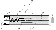
- the booster circuit 6 includes a center electrode 53 of the input unit, a center electrode 56 of the output unit, an electrode 54 of the coupling unit, a ground coil 55, and an insulator 59.
- the center electrode 53 is installed in the microwave plasma plug 50 from the electromagnetic wave oscillator 3 through the input unit 52 and is capacitively coupled through the electrode 54 of the coupling unit and the insulator 59.
- One end of the center electrode 56 of the output part is directly connected to the electrode 54 of the coupling part.
- the other end of the center electrode 56 of the output part is the discharge electrode 5.
- a portion other than the discharge electrode 5 of the center electrode 56 of the output portion is covered with an insulating material 59, and a coil structure of the ground coil 55 is formed around the portion.
- ground coil 55 One end of the ground coil 55 is connected to the electrode 54 of the coupling portion, and the other end is grounded in the vicinity of the discharge electrode.
- the stray capacitance between the ground coil 55 and the outer case 51 and the stray capacitance between the electrode 54 and the outer case 51 in the coupling portion resonate to generate a high voltage.
- the coil structure portion of the ground coil 55 is embedded in the insulating material 59. The generated high voltage is discharged from the discharge electrode 5 toward the ground electrode 57 in the vicinity thereof.
- the booster circuit 6 is built in the microwave plasma plug 50 as shown in FIG.
- the equivalent circuit of the booster circuit 6 is shown in FIG.
- the booster circuit 6 includes a parallel resonant circuit that is capacitively coupled to the electromagnetic wave oscillator 3 and includes a coil L1 and a capacitor C2. Furthermore, a resonance circuit including a coil L2 and a capacitor C3, which is capacitively coupled to the electromagnetic wave oscillator 3, is included.
- the ratio of the frequency of the resonance circuit to the frequency of the parallel resonance circuit is preferably 0.80 or more and 1.20 or less, more preferably 0.90 or more and 1.10 or less, and 0.95 or more and 1 or less. Is more preferably 0.05 or less, and most preferably 1.00.
- a series resonance circuit can be further provided on the discharge electrode 58 pole side from the parallel resonance circuit.
- the booster circuit 60 in this case is shown in FIG. 6, and the equivalent circuit of the booster circuit 60 is shown in FIG.
- the booster circuit 60 includes a series resonance circuit including a coil L2 and a capacitor C4 on the discharge electrode 58 side of a parallel resonance circuit including a coil L1 and a capacitor C2.
- the end of the discharge electrode 58 that also serves as the coil L2 is separated from the electrode 54 of the coupling portion, and a capacitor C4 is configured between the end portion of the discharge electrode 58 and the electrode 54.
- the resonance frequencies of the parallel resonance circuit and the series resonance circuit are substantially the same.
- the control device 4 In a specific plasma generation operation, first, the control device 4 outputs an electromagnetic wave oscillation signal under conditions that cause spark discharge.
- the electromagnetic wave power source 2 When receiving the electromagnetic wave oscillation signal from the control device 4, the electromagnetic wave power source 2 outputs a pulse current with a predetermined duty ratio over a predetermined set time.
- the electromagnetic wave oscillator 3 outputs an electromagnetic wave pulse with a predetermined duty ratio over a set time.
- the electromagnetic wave pulse output from the electromagnetic wave oscillator 3 becomes a high voltage by the boost circuit 6 resonating between the stray capacitance between the ground coil 55 and the outer case 51 and the stray capacitance between the electrode 54 and the outer case 51 of the coupling portion.
- discharge occurs from the discharge electrode 5 toward the ground electrode 57, and spark is generated. Due to this spark, electrons are emitted from the gas molecules in the vicinity of the discharge electrode 5 to generate plasma.
- the control device 4 outputs an electromagnetic wave oscillation signal under a condition for maintaining and expanding the plasma.
- the electromagnetic wave power source 2 When receiving the electromagnetic wave oscillation signal from the control device 4, the electromagnetic wave power source 2 outputs a pulse current with a predetermined duty ratio over a predetermined set time.
- the electromagnetic wave oscillator 3 outputs an electromagnetic wave pulse with a predetermined duty ratio over a set time.
- the microwave (assist microwave) output from the electromagnetic wave oscillator 3 is discharged from the discharge electrode 5 through the booster circuit 6. Thereby, the plasma generated by the spark discharge can be maintained and expanded.
- FIG. 5 shows an example of a predetermined oscillation pattern including an electromagnetic wave pulse under a condition for causing a spark discharge and an electromagnetic wave pulse under a condition for maintaining and expanding the generated plasma in the plasma generation apparatus 1 of the present embodiment. That is, in order to generate a spark discharge in the discharge electrode 5 and generate plasma, it is necessary to radiate a microwave having a certain power or more. Such a microwave may be a single pulse, or a plurality of pulses over a predetermined duty ratio and a predetermined set time as required. Thereafter, the plasma can be maintained and expanded by oscillating microwaves for a predetermined set time with a predetermined duty ratio. The electric power necessary for maintaining and expanding the plasma can be kept lower than the electric power necessary for causing the spark discharge.
- the generated plasma functions as a resistance, so that the voltage is lowered. Therefore, even when the oscillation of the electromagnetic wave pulse under the condition for causing the spark discharge is continued, after the plasma is generated by the spark, it is naturally controlled and becomes a low voltage, and the plasma can be maintained and expanded.
- the plasma generating apparatus 1 can generate a high voltage by including the booster circuit 6 that resonates the electromagnetic wave, and can generate a spark only by the electromagnetic wave. Therefore, plasma can be generated, maintained, and expanded only in the target space with the electromagnetic wave, and only the electromagnetic wave power source 2 is sufficient as the power source, and a complicated transmission line or the like is not required. Furthermore, since a predetermined oscillation pattern including an electromagnetic wave pulse under conditions that cause spark discharge and an electromagnetic pulse under conditions that expand and maintain the generated plasma is used, plasma generation, expansion, and maintenance can be efficiently performed only by electromagnetic waves. And total power consumption can be reduced. Further, since the center electrode 56 of the output portion passes through the inside of the coil structure portion of the ground coil 55, the diameter of the microwave plasma plug can be further reduced.
- the first modification of the first embodiment is partially different from the first embodiment in the plasma generation operation. That is, as shown in FIG. 6, first, the control device 4 outputs an electromagnetic wave oscillation signal under a condition for generating non-equilibrium plasma before outputting an electromagnetic wave oscillation signal under a condition for causing spark discharge. Thereby, the electromagnetic wave power source 2 outputs a pulse current for a predetermined set time with a predetermined duty ratio. An electromagnetic pulse is oscillated by the output pulse current, and is discharged from the discharge electrode 5 through the high voltage circuit 6. By this discharge, electrons are emitted from the gas molecules in the target space, and non-equilibrium plasma is generated.
- an electromagnetic pulse under the condition for generating such non-equilibrium plasma an electromagnetic pulse under the condition for causing streamer discharge is preferable.
- a dielectric barrier discharge electrode (not shown) is further provided in the vicinity of the discharge electrode 5 of the microwave plasma plug 50.
- the dielectric barrier discharge electrode is covered with an insulator. Due to the discharge from the dielectric barrier discharge electrode, non-equilibrium plasma is generated in the target space. Similarly to the microwave plasma plug 50, the discharge from the dielectric barrier discharge electrode is also controlled by the control device 4.
- the discharge electrode 5 causes a spark discharge and the assist discharge.
- the installation position of the electromagnetic wave radiation antenna covered with the insulator in this modification is not particularly limited as long as the effect of the present invention is not hindered, but is located in the vicinity of the discharge electrode 5 of the microwave plasma plug 50, It is preferable to dispose the dielectric barrier discharge in the region where the spark discharge occurs.
- the pattern shown in FIG. 6 is mentioned.
- the control device 4 first outputs an electromagnetic wave oscillation signal under a condition for generating non-equilibrium plasma by dielectric barrier discharge.
- the electromagnetic wave power source 2 outputs a pulse current at a predetermined duty ratio for a predetermined set time, and promotes discharge from the dielectric barrier discharge electrode. By this discharge, electrons are emitted from the gas molecules in the target space, and non-equilibrium plasma is generated.
- the control device 4 outputs an electromagnetic wave oscillation signal under conditions that cause spark discharge.
- the electromagnetic wave power source 2 When receiving the electromagnetic wave oscillation signal from the control device 4, the electromagnetic wave power source 2 outputs a pulse current with a predetermined duty ratio over a predetermined set time.
- the electromagnetic wave oscillator 3 outputs an electromagnetic wave pulse with a predetermined duty ratio over a set time.
- the electromagnetic wave pulse output from the electromagnetic wave oscillator 3 causes a spark discharge through a booster circuit. By this spark discharge, electrons are emitted from gas molecules in the target space, and plasma is generated.
- the control device 4 gives energy to the plasma and outputs an electromagnetic wave oscillation signal that causes discharge under conditions for expanding and maintaining the plasma.
- the electromagnetic wave power source 2 When receiving the electromagnetic wave oscillation signal from the control device 4, the electromagnetic wave power source 2 outputs a pulse current with a predetermined duty ratio over a predetermined set time.
- the electromagnetic wave oscillator 3 outputs an electromagnetic wave pulse with a predetermined duty ratio over a set time.
- the microwave (assist microwave) output from the electromagnetic wave oscillator 3 is discharged from the discharge electrode 5 through the booster circuit, and can give energy to the plasma generated by the spark discharge, thereby expanding and maintaining the plasma.
- the energy state of the gas molecules in the target space can be increased by the dielectric barrier discharge, so that the power required for the spark discharge can be reduced.
- the total amount of electric power required in the entire process can be reduced.
- the voltage used in spark discharge can be reduced, the wear of the discharge electrode 5 can also be prevented.
- Embodiment 2 is an internal combustion engine 10 provided with a plasma generation device 12 according to the present invention.
- the plasma generator 12 generates microwave plasma using the combustion chamber 20 as a target space.
- the internal combustion engine 10 is a direct-injection gasoline engine.
- the internal combustion engine 10 includes an internal combustion engine body 11 and a plasma generator 12.
- the internal combustion engine body 11 includes a cylinder block 21, a cylinder head 22, and a piston 23.
- the cylinder block 21 is formed with a plurality of cylinders having a circular cross section.
- a piston 23 is provided in each cylinder 24 so as to reciprocate.
- the piston 23 is connected to the crankshaft via a connecting rod (not shown).
- the crankshaft is rotatably supported by the cylinder block 21.
- the cylinder head 22 is placed on the cylinder block 21 with the gasket 18 in between.
- the cylinder head 22 defines the combustion chamber 20 together with the cylinder 24 and the piston 23.
- the cylinder head 22 is provided with one microwave plasma plug 50 for each cylinder 24.
- the tip portion 50a of the microwave plasma plug 50 functions as a discharge electrode.
- the microwave plasma plug 50 constitutes a part of the plasma generation device 12.
- the microwave plasma plug 50 has the same shape as a spark plug of a conventional automobile engine, and incorporates an electromagnetic wave oscillator 3 and a discharge electrode 5.
- an intake port 25 and an exhaust port 26 are formed for each cylinder 24.
- the intake port 25 is provided with an intake valve 27 that opens and closes the intake port 25.
- the exhaust port 26 is provided with an exhaust valve 28 for opening and closing the exhaust port 26.
- the cylinder head 22 is provided with one injector 29 for each cylinder 24.
- the injector 29 projects into the combustion chamber 20 from between the openings of the two intake ports 25.
- the injector 29 injects fuel from a plurality of nozzles in different directions.
- the injector 29 injects fuel toward the top surface of the piston 23.
- plasma generation operation in the internal combustion engine of the present embodiment will be described.
- plasma is generated by discharging from the tip portion 50a of the microwave plasma plug 50 that functions as a discharge electrode.
- the control device 4 outputs an electromagnetic wave oscillation signal that causes a spark discharge.
- the electromagnetic wave power source 2 When receiving the electromagnetic wave oscillation signal from the control device 4, the electromagnetic wave power source 2 outputs a pulse current with a predetermined duty ratio over a predetermined set time.
- the electromagnetic wave oscillator 3 outputs an electromagnetic wave pulse with a predetermined duty ratio over a set time.
- the electromagnetic wave pulse output from the electromagnetic wave oscillator 3 becomes a high voltage by the booster circuit 6 incorporated in the microwave plasma plug 50 and causes a spark discharge in the vicinity of the tip portion 50 a of the microwave plasma plug 50. Electrons are emitted from the fuel gas molecules in the reaction chamber 20 by this spark discharge, and plasma is generated.
- the control device 4 gives energy to the plasma and outputs an electromagnetic wave oscillation signal under a condition for expanding and maintaining the plasma.
- the electromagnetic wave power source 2 When receiving the electromagnetic wave oscillation signal from the control device 4, the electromagnetic wave power source 2 outputs a pulse current at a predetermined duty ratio for a predetermined set time.
- the electromagnetic wave oscillator 3 outputs an electromagnetic wave pulse with a predetermined duty ratio over a set time.
- the electromagnetic wave pulse output from the electromagnetic wave oscillator 3 becomes a high voltage through the booster circuit 6 and discharges at the tip portion 50a of the microwave plasma plug 50, giving energy to the plasma generated by the spark discharge, and expanding the plasma. Can be maintained.
- FIG. 1 As an example of a predetermined oscillation pattern including an electromagnetic wave pulse under a condition for causing a spark discharge and an electromagnetic wave pulse under a condition for expanding and maintaining the generated plasma, FIG. The pattern shown can be mentioned. That is, in order to generate a spark discharge in the reaction chamber 20 and generate plasma, an electromagnetic wave pulse with a certain power or more is required. Such an electromagnetic wave pulse may be a single pulse, or a plurality of pulses over a predetermined duty ratio and a predetermined set time as required. Thereafter, in order to maintain and expand the generated plasma, an electromagnetic wave pulse is oscillated over a predetermined set time with a predetermined duty ratio. The expansion and maintenance of this plasma requires only a lower power than that required to cause a spark discharge.
- an internal combustion engine including a conventional plasma generation device including a spark plug using a high voltage and a microwave radiation antenna by using the same plasma generation device as that of the first embodiment an internal combustion engine including a conventional plasma generation device including a spark plug using a high voltage and a microwave radiation antenna by using the same plasma generation device as that of the first embodiment.
- a plurality of power sources are not required, and complicated transmission lines are not required.
- the electromagnetic wave oscillator 3 and the discharge electrode 5 can be incorporated in a microwave plasma plug 50 having the same shape as a spark plug of a conventional automobile engine. For this reason, when the plasma generating apparatus of the present embodiment is used for an automobile engine, it is not necessary to change the structure of the engine itself.
- the first modification of the second embodiment includes the same plasma generator as that of the first modification of the first embodiment. Details of such a plasma generation apparatus have been described in detail in Modification 1 of Embodiment 1, and thus description thereof is omitted here. In the internal combustion engine of the present modification, the total amount of necessary electric power can be reduced by including such a plasma generation device.
- the second modification of the second embodiment includes the same plasma generator as that of the second modification of the first embodiment. Details of such a plasma generation apparatus have been described in detail in Modification 2 of Embodiment 1, and thus description thereof is omitted here.
- the installation position of the dielectric barrier discharge electrode in this modification is not particularly limited as long as the effect of the present invention is not hindered, but it is in the vicinity of the discharge electrode 5 so as to cause the dielectric barrier discharge in the spark discharge region. It is preferable that it is arrange
- the plasma generation apparatus can be used as an exhaust gas decomposition apparatus.
- the exhaust gas decomposition apparatus includes an electromagnetic wave power source, an electromagnetic wave oscillator, a control device, a microwave plasma plug containing a booster circuit and a discharge electrode, and a microwave resonance cavity (cavity) that resonates a predetermined electromagnetic wave band. Since the plasma generating apparatus of the present invention can generate effective plasma only by electromagnetic waves, a complicated system such as a transmission line is unnecessary, and further contributes to reduction of power consumption.
- harmful emissions, chemical substances, suspended particulate matter, soot, etc. are chemically oxidized and reacted using products (OH radicals, ozone (O 3 )) by plasma.
- products OH radicals, ozone (O 3 )
- plasma can be efficiently generated in the fluid in the microwave resonant cavity (cavity).
- the plasma generating apparatus of the present invention is suitably used as an ozone generating / sterilizing / disinfecting apparatus and deodorizing apparatus.
- the plasma generation apparatus of the present invention is used, high-pressure steam containing moisture can be efficiently converted into a large amount of OH radicals and O 3 .
- the exhaust gas quantity of OH radicals with have a strong oxidizing power of O 3 to decompose into harmless gases, to generate a large amount of O 3 for the ozone layer repair of stratospheric destroyed by freon Can do.
- the plasma generation apparatus of the present invention can improve the generation / expansion efficiency of plasma with respect to the electric power used, these apparatuses including the plasma generation apparatus perform ozone generation / sterilization / disinfection / deodorization more efficiently. I can do this.
- the plasma generation apparatus of the present invention can generate, expand, and maintain plasma only with electromagnetic waves, so that only one power source is required and no complicated transmission line or the like is required. Furthermore, since a predetermined oscillation pattern including an electromagnetic wave pulse under conditions that cause spark discharge and an electromagnetic pulse under conditions that expand and maintain the generated plasma is used, plasma generation, expansion, and maintenance can be efficiently performed only by electromagnetic waves. And the total amount of power consumption can be reduced. Therefore, the plasma generation apparatus of the present invention is suitably used for internal combustion engines such as automobile engines, exhaust gas decomposition apparatuses, and the like.
Landscapes
- Engineering & Computer Science (AREA)
- Physics & Mathematics (AREA)
- Chemical & Material Sciences (AREA)
- Combustion & Propulsion (AREA)
- Mechanical Engineering (AREA)
- General Engineering & Computer Science (AREA)
- Plasma & Fusion (AREA)
- Electromagnetism (AREA)
- Optics & Photonics (AREA)
- Spectroscopy & Molecular Physics (AREA)
- Plasma Technology (AREA)
- Ignition Installations For Internal Combustion Engines (AREA)
Abstract
本発明は、電磁波を放射することにより電磁波プラズマを生成するプラズマ生成装置において、複数の電源、複雑なシステム等を必要とせず、必要な電力量を低減し、プラズマの発生、拡大及び維持を効率よく行えるプラズマ生成装置の供給を課題とする。本発明は、電磁波を発振する電磁波発振器、及び上記電磁波発振器を制御する制御装置を備えるプラズマ生成装置であって、上記電磁波発振器から発振される電磁波を共振させて高電圧を発生させる昇圧回路と、上記昇圧回路により発生した高電圧を放電させる放電電極とを備えることを特徴とする。
Description
本発明は、プラズマ生成装置及びそのプラズマ生成装置を備えた内燃機関に関する。
従来から、対象空間に電磁波を放射して電磁波プラズマを生成するプラズマ生成装置が知られている。例えば特開2009-38025号公報及び特開2006-132518号公報には、この種のプラズマ生成装置が記載されている。
特開2009-38025号公報には、スパークプラグの放電ギャップでスパーク放電を生じさせると共に、その放電ギャップに向けてマイクロ波を放射してプラズマを拡大するプラズマ生成装置が記載されている。このプラズマ生成装置では、スパーク放電により生成されたプラズマがマイクロ波パルスからエネルギーを受ける。これにより、プラズマ領域の電子が加速され、電離が促進されて、プラズマの体積が増大する。
また、特開2006-132518号公報には、電磁波放射器から燃焼室内に電磁波を放射することによりプラズマ放電を発生させる内燃機関の点火装置が開示されている。ピストンの上面には、ピストンから絶縁された点火用電極が設けられている。点火用電極は、その近傍にて燃焼室内の電磁波の電界強度を局所的に高める役割を果たす。これにより点火用電極の近傍にてプラズマ放電が生成される。
しかし、特開2009-38025号公報に記載のプラズマ生成装置では、スパークプラグにおいて放電を起こさせるための高電圧電源、及びマイクロ波を放射するための高周波電源の少なくとも2つの電源が必要となる。例えばプラズマ生成装置を自動車エンジン等の燃焼室に用いる場合には設置スペースに限界があるため、このように複数の電源を要するプラズマ生成装置では設置場所を確保することが難しいという不都合がある。また、このようなプラズマ生成装置における伝送システムとしては、従来のスパークプラグに対する高電圧配送システムと電磁波配送システムの双方が必要とされるため、高度に複雑化される。一方、特開2006-132518号公報に記載のプラズマ生成装置は、電磁波のみを用いてプラズマを生成するため、電源は1つしか必要ないものの電磁波のみで着火及び燃焼反応を起こさせるためには、高周波電源から多量の電力を供給する必要がある。
本発明は、かかる点に鑑みてなされたものであり、その目的は、対象空間に電磁波によりプラズマを生成するプラズマ生成装置において、複数の電源、複雑なシステム等を必要とせず、さらには、必要な電力量を低減し、プラズマの発生、拡大及び維持を効率よく行うことができるプラズマ生成装置を供給することである。
上記課題を解決するためになされた発明は、
電磁波を発振する電磁波発振器、及び上記電磁波発振器を制御する制御装置を備えるプラズマ生成装置であって、
上記電磁波発振器から発振される電磁波を共振させて高電圧を発生させる昇圧回路と、
上記昇圧回路により発生した高電圧を放電させる放電電極とを備えることを特徴とするものである。
電磁波を発振する電磁波発振器、及び上記電磁波発振器を制御する制御装置を備えるプラズマ生成装置であって、
上記電磁波発振器から発振される電磁波を共振させて高電圧を発生させる昇圧回路と、
上記昇圧回路により発生した高電圧を放電させる放電電極とを備えることを特徴とするものである。
本発明のプラズマ生成装置は、電磁波のみでプラズマを生成、拡大、維持させることができるため、電源は一つで足りる。さらに当該プラズマ生成装置は、電磁波を共振させる昇圧回路を含むことで高電圧を発生させることができ、電磁波のみで効率よくスパークを起こしプラズマを発生させることができる。
上記昇圧回路は、上記電磁波発振器と容量結合した共振回路を含むことが好ましい。当該プラズマ生成装置は、上記共振回路を含むことで、効率的に高電圧を発生させることができ、それにより電磁波のみで安定してスパークを生じさせることができる。
上記昇圧回路は、上記共振回路を複数含むことが好ましい。当該プラズマ装置は、上記昇圧回路が複数の共振回路を含むことで、より高い電圧を発生させることが可能となるため、電磁波のみでより安定してスパークを生じさせることができる。
上記共振回路の少なくとも1つは、並列共振回路であることが好ましい。当該プラズマ生成装置は、上記並列共振回路を含むことで、より効率的に高電圧を発生させることができるため、電磁波のみで安定してスパークを生じさせることができる。
また、上記並列共振回路より放電電極側に、さらに直列共振回路を備えることができる。直列共振回路を備えることで、放電電極からプラズマが発生し、低抵抗になっても電磁波発振器との整合を維持し、電磁波の反射を低減する。この場合、並列共振回路と直列共振回路の共振周波数は略同一とすることが好ましい。
上記制御装置は、上記放電電極においてスパーク放電を引き起こす条件の電磁波パルスと、上記スパーク放電により生じたプラズマを拡大・維持させる条件の電磁波パルスとを含む発振パターンに従って発振するよう上記電磁波発振器を制御することが好ましい。
当該プラズマ生成装置は、スパーク放電を起こす条件の電磁波パルスと、この電磁波パルスよりも低い電力を用い、生じたプラズマを拡大・維持させる条件の電磁波パルスとを含む発振パターンを用いることで、プラズマの生成、拡大、維持を効率よく行うことができ、その結果としてトータルの消費電力を低減することができる。
上記発振パターンは、上記スパーク放電を引き起こす条件の電磁波パルスの前に、非平衡プラズマを生成させる条件の電磁波パルスをさらに含むことが好ましい。本発明のプラズマ生成装置は、スパーク放電の前に非平衡プラズマを生成させることで、スパーク放電の際に必要な電力をより低減することができる。
上記非平衡プラズマを生成させる条件の電磁波パルスは、ストリーマ放電を起こす条件の電磁波パルスであることが好ましい。上記ストリーマ放電は、例えば1マイクロ秒未満の短パルス電圧を印加することで、簡便に非平衡プラズマを生成することができる。
本発明のプラズマ生成装置は、内燃機関用として好適に用いられる。当該プラズマ生成装置は、電磁波のみで効率良くプラズマを生成、拡大、維持する事ができるため、内燃機関に用いた場合に、燃焼効率をより向上することができる。
本発明は、上述の本発明のプラズマ生成装置と、燃焼室が形成された内燃機関本体とを備える内燃機関も含む。
本発明の内燃機関は、電磁波のみで効率良くプラズマを生成、維持、拡大する事ができる上述のプラズマ生成装置を備えているため、燃焼効率により優れる。
本発明のプラズマ生成装置は、電磁波を共振させる昇圧回路を含むことで高電圧を発生させることができ、電磁波のみでスパークを起こすことができる。そのため、当該プラズマ生成装置においては、電源が一つで足り、複雑な伝送線路等を必要としない。また、当該プラズマ生成装置は、スパーク放電を起こす条件の電磁波パルスと、生じたプラズマを拡大・維持させるための放電を起こす条件の電磁波パルスとを含む所定の発振パターンを用いる。そのため、電磁波のみによってもプラズマの生成、拡大、維持を効率よく行うことができ、消費電力を低減することができる。
以下、本発明の実施形態を図面に基づいて詳細に説明する。なお、以下の実施形態は、本質的に好ましい例示であって、本発明、その適用物、あるいはその用途の範囲を制限することを意図するものではない。
<実施形態1>プラズマ生成装置
本実施形態1は、本発明に係るプラズマ生成装置である。当該プラズマ生成装置は、図1に示すように、電磁波用電源2、電磁波発振器3、昇圧回路6、放電電極5及び制御装置4を備えている。
本実施形態1は、本発明に係るプラズマ生成装置である。当該プラズマ生成装置は、図1に示すように、電磁波用電源2、電磁波発振器3、昇圧回路6、放電電極5及び制御装置4を備えている。
電磁波用電源2は、制御装置4から電磁波発振信号(例えばTTL信号)を受けると、所定のデューティー比、パルス時間等を設定したパターンで電磁波発振器3にパルス電流を出力する。
電磁波発振器3は、例えば半導体発振器である。電磁波発振器3は、電磁波用電源2に電気的に接続されている。電磁波発振器3は、電磁波用電源2からパルス電流を受けると、昇圧回路6にマイクロ波パルスを出力する。
昇圧回路6は、図3に示すように、入力部の中心電極53、出力部の中心電極56、結合部の電極54、接地コイル55及び絶縁体59を備える。中心電極53は、電磁波発振器3から入力部52を介してマイクロ波プラズマプラグ50内に設置され、結合部の電極54と絶縁体59を介して容量結合している。出力部の中心電極56の一方の端部は結合部の電極54に直結している。出力部の中心電極56のもう一方の端部は放電電極5となっている。出力部の中心電極56の放電電極5以外の部分は絶縁材59で覆われており、その周囲に接地コイル55のコイル構造が形成されている。接地コイル55の一方の端部は結合部の電極54に接続しており、もう一方の端部は放電電極付近で接地している。接地コイル55と外ケース51との浮遊容量、及び結合部の電極54と外ケース51との浮遊容量が共振することで高電圧を発生する構造になっている。接地コイル55のコイル構造部分は、絶縁材59中に埋め込まれる構造となっている。発生した高電圧は、放電電極5からその近傍の接地電極57に向かって放電される。なお、昇圧回路6は、図3に示すようにマイクロ波プラズマプラグ50に内蔵されている。
昇圧回路6の等価回路を図4に示す。昇圧回路6は、電磁波発振器3と容量結合した、コイルL1とコンデンサC2とからなる並列共振回路を含んでいる。さらに、電磁波発振器3と容量結合した、コイルL2とコンデンサC3とからなる共振回路を含んでいる。上記並列共振回路の周波数に対する上記共振回路の周波数の比は、0.80以上1.20以下であることが好ましく、0.90以上1.10以下であることがより好ましく、0.95以上1.05以下であることがさらに好ましく、1.00であることが最も好ましい。
また、並列共振回路より放電電58極側に、さらに直列共振回路を備えることができる。この場合の昇圧回路60を図6に、昇圧回路60の等価回路を図7に示す。この昇圧回路60は、コイルL1とコンデンサC2とからなる並列共振回路より放電電極58側に、コイルL2とコンデンサC4とからなる直列共振回路を備えている。具体的には、図6に示すように、コイルL2を兼ねる放電電極58の末端が結合部の電極54と分離し、放電電極58の末端部分と電極54との間でコンデンサC4を構成する。直列共振回路を備えることで、放電電極からプラズマが発生し、低抵抗になっても電磁波発振器との整合を維持し、電磁波の反射を低減する。この場合、並列共振回路と直列共振回路の共振周波数は略同一とすることが好ましい。
-プラズマ生成装置の動作-
プラズマ生成装置1のプラズマ生成動作について説明する。プラズマ生成動作では、放電電極5からの放電により、放電電極5の近傍にプラズマが生じる。
プラズマ生成装置1のプラズマ生成動作について説明する。プラズマ生成動作では、放電電極5からの放電により、放電電極5の近傍にプラズマが生じる。
具体的なプラズマ生成動作では、まず制御装置4が、スパーク放電を起こす条件の電磁波発振信号を出力する。電磁波用電源2は、制御装置4からこのような電磁波発振信号を受けると、所定のデューティー比で所定の設定時間に亘ってパルス電流を出力する。電磁波発振器3は、設定時間に亘って電磁波パルスを所定のデューティー比で出力する。電磁波発振器3から出力された電磁波パルスは、昇圧回路6により、接地コイル55と外ケース51との浮遊容量、及び結合部の電極54と外ケース51との浮遊容量が共振することで高電圧となり、放電電極5から接地電極57に向かって放電が起こり、スパークを生じさせる。このスパークにより放電電極5の近傍のガス分子から電子が放出され、プラズマが生成される。
引き続き制御装置4は、上記プラズマを維持・拡大する条件の電磁波発振信号を出力する。電磁波用電源2は、制御装置4からこのような電磁波発振信号を受けると、所定のデューティー比で所定の設定時間に亘ってパルス電流を出力する。電磁波発振器3は、設定時間に亘って電磁波パルスを所定のデューティー比で出力する。電磁波発振器3から出力されたマイクロ波(アシストのマイクロ波)は、昇圧回路6を経て放電電極5から放電される。これにより、スパーク放電によって生じたプラズマを維持・拡大させることができる。
本実施形態のプラズマ生成装置1における、スパーク放電を起こす条件の電磁波パルスと、生じたプラズマを維持・拡大させる条件の電磁波パルスとを含む所定の発振パターンの一例を図5に示した。すなわち、放電電極5においてスパーク放電を起こし、プラズマを発生させるためには、ある一定以上の電力のマイクロ波を放射することが必要である。このようなマイクロ波としては、一回のパルスであってもよいし、必要に応じて所定のデューティー比、所定の設定時間に亘る複数回のパルスであってもよい。その後、生じたプラズマに対して、所定のデューティー比で所定の設定時間に亘ってマイクロ波を発振することで、プラズマを維持・拡大させることができる。このプラズマの維持・拡大のために必要な電力は、スパーク放電を起こすのに必要な電力よりも低く抑えることができる。
なお、上述のように、スパーク放電を起こすことによりプラズマが発生すると、生じたプラズマが抵抗として機能するため電圧が低くなる。そのため、スパーク放電を起こす条件の電磁波パルスの発振を継続した場合であっても、スパークによりプラズマを生じさせた後自然に制御がかかり低電圧となり、プラズマを維持・拡大させることも可能である。
電磁波発振信号の立ち上がり時点から所定の設定時間が経過すると、マイクロ波パルスの発振が停止され、マイクロ波プラズマが消滅する。
-実施形態1の効果-
本実施形態1のプラズマ生成装置1は、電磁波を共振させる昇圧回路6を含むことで高電圧を発生させることができ、電磁波のみでスパークを起こすことができる。そのため、対象空間において、電磁波のみでプラズマを生成、維持、拡大させることができ、電源は電磁波用電源2のみで足り、複雑な伝送線路等を必要としない。さらには、スパーク放電を起こす条件の電磁波パルスと、生じたプラズマを拡大・維持させる条件の電磁波パルスを含む所定の発振パターンを用いるため、電磁波のみによってもプラズマの生成、拡大、維持を効率よく行うことができ、トータルでの消費電力を低減することができる。また、出力部の中心電極56が接地コイル55のコイル構造部分の内部を通る構造となっていることで、マイクロ波プラズマプラグの径をより細くすることも可能となる。
本実施形態1のプラズマ生成装置1は、電磁波を共振させる昇圧回路6を含むことで高電圧を発生させることができ、電磁波のみでスパークを起こすことができる。そのため、対象空間において、電磁波のみでプラズマを生成、維持、拡大させることができ、電源は電磁波用電源2のみで足り、複雑な伝送線路等を必要としない。さらには、スパーク放電を起こす条件の電磁波パルスと、生じたプラズマを拡大・維持させる条件の電磁波パルスを含む所定の発振パターンを用いるため、電磁波のみによってもプラズマの生成、拡大、維持を効率よく行うことができ、トータルでの消費電力を低減することができる。また、出力部の中心電極56が接地コイル55のコイル構造部分の内部を通る構造となっていることで、マイクロ波プラズマプラグの径をより細くすることも可能となる。
-実施形態1の変形例1-
実施形態1の変形例1では、実施形態1とはプラズマの生成動作が一部異なる。すなわち、図6に示すように、まず制御装置4が、スパーク放電を起こす条件の電磁波発振信号を出力する前に、非平衡プラズマを生成する条件の電磁波発振信号を出力する。これにより、電磁波用電源2は、所定のデューティー比で所定の設定時間に亘ってパルス電流を出力する。出力されたパルス電流により電磁波パルスが発振され、高圧回路6を経て放電電極5から放電される。この放電により対象空間のガス分子から電子が放出され、非平衡プラズマが生成される。この非平衡プラズマにおいては、放出される電子温度のみが高くなり、粒子温度は低温に保たれる。そのため、この条件においては、スパークを生じることはない。しかし、対象空間のガス分子のエネルギー状態が高くなっているため、引き続き行われるスパーク放電のために必要な電力を低減することができる。これらの結果として、本発明のプラズマ生成装置において、全行程において必要とされる電力の合計量を低減させることができる。また、スパーク放電において用いられる電圧を低減させることができるため、放電電極5の摩耗を防止することもできる。
実施形態1の変形例1では、実施形態1とはプラズマの生成動作が一部異なる。すなわち、図6に示すように、まず制御装置4が、スパーク放電を起こす条件の電磁波発振信号を出力する前に、非平衡プラズマを生成する条件の電磁波発振信号を出力する。これにより、電磁波用電源2は、所定のデューティー比で所定の設定時間に亘ってパルス電流を出力する。出力されたパルス電流により電磁波パルスが発振され、高圧回路6を経て放電電極5から放電される。この放電により対象空間のガス分子から電子が放出され、非平衡プラズマが生成される。この非平衡プラズマにおいては、放出される電子温度のみが高くなり、粒子温度は低温に保たれる。そのため、この条件においては、スパークを生じることはない。しかし、対象空間のガス分子のエネルギー状態が高くなっているため、引き続き行われるスパーク放電のために必要な電力を低減することができる。これらの結果として、本発明のプラズマ生成装置において、全行程において必要とされる電力の合計量を低減させることができる。また、スパーク放電において用いられる電圧を低減させることができるため、放電電極5の摩耗を防止することもできる。
このような非平衡プラズマを生成させる条件の電磁波パルスとしては、ストリーマ放電を起こす条件の電磁波パルスが好ましいものとして挙げられる。
-実施形態1の変形例2-
実施形態1の変形例2では、マイクロ波プラズマプラグ50の放電電極5の近傍に誘電体バリア放電用電極(図示省略)をさらに備える。この誘電体バリア放電用電極は絶縁体で覆われている。この誘電体バリア放電用電極からの放電により、対象空間において非平衡プラズマが生成される。上記誘電体バリア放電用電極からの放電も、マイクロ波プラズマプラグ50と同様に制御装置4により制御される。
実施形態1の変形例2では、マイクロ波プラズマプラグ50の放電電極5の近傍に誘電体バリア放電用電極(図示省略)をさらに備える。この誘電体バリア放電用電極は絶縁体で覆われている。この誘電体バリア放電用電極からの放電により、対象空間において非平衡プラズマが生成される。上記誘電体バリア放電用電極からの放電も、マイクロ波プラズマプラグ50と同様に制御装置4により制御される。
引き続き、放電電極5においては、スパーク放電及び上記アシストの放電を起こす。なお、本変形例における絶縁体で覆われている上記電磁波放射アンテナの設置位置としては、本発明の効果を妨げない限り特に限定されないが、マイクロ波プラズマプラグ50の放電電極5近傍に位置し、スパーク放電をおこす領域において誘電体バリア放電を起こすよう配設されていることが好ましい。また、本変形例における電磁波の発振パターンの一例としては、図6に示すパターンが挙げられる。
すなわち、制御装置4は、まず誘電体バリア放電により非平衡プラズマを生成する条件の電磁波発振信号を出力する。これにより、電磁波用電源2は、所定のデューティー比で所定の設定時間に亘ってパルス電流を出力し、上記誘電体バリア放電用電極からの放電を促す。この放電により対象空間のガス分子から電子が放出され、非平衡プラズマが生成される。引き続き制御装置4が、スパーク放電を起こす条件の電磁波発振信号を出力する。電磁波用電源2は、制御装置4からこのような電磁波発振信号を受けると、所定のデューティー比で所定の設定時間に亘ってパルス電流を出力する。電磁波発振器3は、設定時間に亘って電磁波パルスを所定のデューティー比で出力する。電磁波発振器3から出力された電磁波パルスは、昇圧回路を経てスパーク放電を生じさせる。このスパーク放電により対象空間のガス分子から電子が放出され、プラズマが生成される。
次に制御装置4は、上記プラズマにエネルギーを与え、このプラズマを拡大・維持する条件の放電を起こすような電磁波発振信号を出力する。電磁波用電源2は、制御装置4からこのような電磁波発振信号を受けると、所定のデューティー比で所定の設定時間に亘ってパルス電流を出力する。電磁波発振器3は、設定時間に亘って電磁波パルスを所定のデューティー比で出力する。電磁波発振器3から出力されたマイクロ波(アシストのマイクロ波)は、昇圧回路を経て放電電極5より放電され、スパーク放電によって生じたプラズマにエネルギーを与え、プラズマを拡大・維持させることができる。
本変形例においては、誘電体バリア放電により対象空間のガス分子のエネルギー状態を高くすることができるため、スパーク放電のために必要な電力を低減することができる。これらの結果として、本発明のプラズマ生成装置において、全行程において必要とされる電力の合計量を低減させることができる。また、スパーク放電において用いられる電圧を低減させることができるため、放電電極5の摩耗を防止することもできる。
<実施形態2>内燃機関
本実施形態2は、本発明に係るプラズマ生成装置12を備えた内燃機関10である。プラズマ生成装置12は、燃焼室20を対象空間としてマイクロ波プラズマを生成する。内燃機関10は、図2に示すように、直噴式のガソリンエンジンである。内燃機関10は、内燃機関本体11とプラズマ生成装置12とを備えている。
本実施形態2は、本発明に係るプラズマ生成装置12を備えた内燃機関10である。プラズマ生成装置12は、燃焼室20を対象空間としてマイクロ波プラズマを生成する。内燃機関10は、図2に示すように、直噴式のガソリンエンジンである。内燃機関10は、内燃機関本体11とプラズマ生成装置12とを備えている。
内燃機関本体11は、シリンダブロック21とシリンダヘッド22とピストン23とを備えている。シリンダブロック21には、横断面が円形のシリンダが複数形成されている。各シリンダ24内には、ピストン23が往復自在に設けられている。ピストン23は、コネクティングロッドを介して、クランクシャフトに連結されている(図示省略)。クランクシャフトは、シリンダブロック21に回転自在に支持されている。各シリンダ24内においてシリンダ24の軸方向にピストン23が往復運動すると、コネクティングロッドがピストン23の往復運動をクランクシャフトの回転運動に変換する。
シリンダヘッド22は、ガスケット18を挟んで、シリンダブロック21上に載置されている。シリンダヘッド22は、シリンダ24及びピストン23と共に、燃焼室20を区画している。
シリンダヘッド22には、各シリンダ24に対して、マイクロ波プラズマプラグ50が1つずつ設けられている。マイクロ波プラズマプラグ50の先端部分50aは、放電電極として機能する。本実施形態では、マイクロ波プラズマプラグ50が、プラズマ生成装置12の一部を構成している。マイクロ波プラズマプラグ50は、従来の自動車エンジンのスパークプラグと同一形状であり、電磁波発振器3及び放電電極5を内蔵している。
シリンダヘッド22には、各シリンダ24に対して、吸気ポート25及び排気ポート26が形成されている。吸気ポート25には、吸気ポート25を開閉する吸気バルブ27が設けられている。一方、排気ポート26には、排気ポート26を開閉する排気バルブ28が設けられている。
シリンダヘッド22には、各シリンダ24に対して、インジェクター29が1つずつ設けられている。インジェクター29は、2つの吸気ポート25の開口の間から燃焼室20に突出している。インジェクター29は、複数の噴口から互いに異なる方向へ燃料を噴射する。インジェクター29は、ピストン23の頂面に向かって燃料を噴射する。
-内燃機関の動作-
本実施形態の内燃機関におけるプラズマ生成動作について説明する。本実施形態の内燃機関では、放電電極として機能するマイクロ波プラズマプラグ50の先端部分50aから放電することによりプラズマが生成される。
本実施形態の内燃機関におけるプラズマ生成動作について説明する。本実施形態の内燃機関では、放電電極として機能するマイクロ波プラズマプラグ50の先端部分50aから放電することによりプラズマが生成される。
まず制御装置4が、スパーク放電を起こす条件の電磁波発振信号を出力する。電磁波用電源2は、制御装置4からこのような電磁波発振信号を受けると、所定のデューティー比で所定の設定時間に亘ってパルス電流を出力する。電磁波発振器3は、設定時間に亘って電磁波パルスを所定のデューティー比で出力する。電磁波発振器3から出力された電磁波パルスは、マイクロ波プラズマプラグ50に内臓された昇圧回路6により高圧となり、マイクロ波プラズマプラグ50の先端部分50a近傍においてスパーク放電を生じさせる。このスパーク放電により反応室20内の燃料ガス分子から電子が放出され、プラズマが生成される。
引き続き制御装置4は、上記プラズマにエネルギーを与え、このプラズマを拡大・維持する条件の電磁波発振信号を出力する。電磁波用電源2は、制御装置4からこのような電磁波発振信号を受けると、所定のデューティー比で所定の設定時間に亘ってパルス電流を出力する。電磁波発振器3は、設定時間に亘って電磁波パルスを所定のデューティー比で出力する。電磁波発振器3から出力された電磁波パルスは、昇圧回路6を経て高圧となり、マイクロ波プラズマプラグ50の先端部分50aにおいて放電を起こし、上記スパーク放電によって生じたプラズマにエネルギーを与え、上記プラズマを拡大・維持させることができる。
本実施形態の内燃機関における、スパーク放電を起こす条件の電磁波パルスと、生じたプラズマを拡大・維持させる条件の電磁波パルスを含む所定の発振パターンの一例としては、実施形態1と同様に図5に示すパターンを挙げることができる。すなわち、反応室20においてスパーク放電を起こし、プラズマを発生させるためには、ある一定以上の電力の電磁波パルスが必要である。このような電磁波パルスとしては、一回のパルスであってもよいし、必要に応じて所定のデューティー比、所定の設定時間に亘る複数回のパルスであってもよい。その後、生じたプラズマを維持・拡大させるためには、所定のデューティー比で所定の設定時間に亘って電磁波パルスが発振される。このプラズマの拡大・維持には、スパーク放電を起こすのに必要な電力よりも低い電力しか必要としない。
-実施形態2の効果-
本実施形態2の内燃機関においては、実施形態1と同様のプラズマ生成装置を用いていることで、高電圧を利用した点火プラグとマイクロ波放射アンテナとを備える従来のプラズマ生成装置を備える内燃機関のように複数の電源を必要とせず、複雑な伝送線路等も必要としない。さらに、本実施形態の内燃機関においては、電磁波発振器3及び放電電極5は、従来の自動車エンジンのスパークプラグと同一形状のマイクロ波プラズマプラグ50に内蔵することができる。そのため、本実施形態のプラズマ生成装置を自動車エンジンに用いる場合には、エンジン自体の構造変更を必要としない。
本実施形態2の内燃機関においては、実施形態1と同様のプラズマ生成装置を用いていることで、高電圧を利用した点火プラグとマイクロ波放射アンテナとを備える従来のプラズマ生成装置を備える内燃機関のように複数の電源を必要とせず、複雑な伝送線路等も必要としない。さらに、本実施形態の内燃機関においては、電磁波発振器3及び放電電極5は、従来の自動車エンジンのスパークプラグと同一形状のマイクロ波プラズマプラグ50に内蔵することができる。そのため、本実施形態のプラズマ生成装置を自動車エンジンに用いる場合には、エンジン自体の構造変更を必要としない。
-実施形態2の変形例1-
実施形態2の変形例1においては、実施形態1の変形例1と同様のプラズマ生成装置を備えている。このようなプラズマ生成装置の詳細については、実施形態1の変形例1において詳細に説明したので、ここでの説明を省略する。本変形例の内燃機関においては、このようなプラズマ生成装置を備えていることで、必要な電力の合計量を低減させることができる。
実施形態2の変形例1においては、実施形態1の変形例1と同様のプラズマ生成装置を備えている。このようなプラズマ生成装置の詳細については、実施形態1の変形例1において詳細に説明したので、ここでの説明を省略する。本変形例の内燃機関においては、このようなプラズマ生成装置を備えていることで、必要な電力の合計量を低減させることができる。
-実施形態2の変形例2-
実施形態2の変形例2では、実施形態1の変形例2と同様のプラズマ生成装置を備えている。このようなプラズマ生成装置の詳細については、実施形態1の変形例2において詳細に説明したので、ここでの説明を省略する。なお、本変形例における誘電体バリア放電用電極の設置位置としては、本発明の効果を妨げない限り特に限定されないが、スパーク放電をおこす領域において誘電体バリア放電を起こすよう、放電電極5の近傍に配設されていることが好ましい。本変形例の内燃機関においては、このようなプラズマ生成装置を備えていることで、必要な電力の合計量を低減させることができる。
実施形態2の変形例2では、実施形態1の変形例2と同様のプラズマ生成装置を備えている。このようなプラズマ生成装置の詳細については、実施形態1の変形例2において詳細に説明したので、ここでの説明を省略する。なお、本変形例における誘電体バリア放電用電極の設置位置としては、本発明の効果を妨げない限り特に限定されないが、スパーク放電をおこす領域において誘電体バリア放電を起こすよう、放電電極5の近傍に配設されていることが好ましい。本変形例の内燃機関においては、このようなプラズマ生成装置を備えていることで、必要な電力の合計量を低減させることができる。
<実施形態3>排ガス分解装置
本発明に係るプラズマ生成装置は、排ガス分解装置として用いることができる。この排ガス分解装置は、電磁波用電源、電磁波発振器、制御装置、昇圧回路及び放電電極を内臓するマイクロ波プラズマプラグ、並びに所定の電磁波帯域を共振するマイクロ波共振空洞(キャビティ)を備える。本発明のプラズマ生成装置は、電磁波のみにより有効なプラズマを生成することができるため、複雑な伝送線路等のシステムが不要であり、さらには使用電力の低減にも資する。
本発明に係るプラズマ生成装置は、排ガス分解装置として用いることができる。この排ガス分解装置は、電磁波用電源、電磁波発振器、制御装置、昇圧回路及び放電電極を内臓するマイクロ波プラズマプラグ、並びに所定の電磁波帯域を共振するマイクロ波共振空洞(キャビティ)を備える。本発明のプラズマ生成装置は、電磁波のみにより有効なプラズマを生成することができるため、複雑な伝送線路等のシステムが不要であり、さらには使用電力の低減にも資する。
本実施形態の排ガス分解装置においては、有害排出物、化学物質、浮遊粒子状物質、スス等をプラズマによる生成物(OHラジカル、オゾン(O3))を利用して化学的に酸化、反応させ、無害化するために、マイクロ波共振空洞(キャビティ)内流体に、効率よくプラズマを発生させることができる。
<実施形態4>オゾン発生・滅菌・消毒装置、消臭装置
本発明のプラズマ生成装置は、オゾン発生・滅菌・消毒装置、消臭装置として好適に用いられる。本発明のプラズマ生成装置を用いると、水分を含んだ高圧蒸気を多量のOHラジカル、O3に効率良く変換することができる。これにより、例えば排気ガスを多量のOHラジカル、O3の強力な酸化力をもって無害なガスに分解するとともに、フロン等で破壊された成層圏のオゾン層修復のために多量のO3を発生させることができる。本発明のプラズマ生成装置は、用いる電力に対するプラズマの発生・拡大効率を向上させることができるため、当該プラズマ生成装置を備えるこれらの装置は、より効率よくオゾン発生・滅菌・消毒・消臭を行うこができる。
本発明のプラズマ生成装置は、オゾン発生・滅菌・消毒装置、消臭装置として好適に用いられる。本発明のプラズマ生成装置を用いると、水分を含んだ高圧蒸気を多量のOHラジカル、O3に効率良く変換することができる。これにより、例えば排気ガスを多量のOHラジカル、O3の強力な酸化力をもって無害なガスに分解するとともに、フロン等で破壊された成層圏のオゾン層修復のために多量のO3を発生させることができる。本発明のプラズマ生成装置は、用いる電力に対するプラズマの発生・拡大効率を向上させることができるため、当該プラズマ生成装置を備えるこれらの装置は、より効率よくオゾン発生・滅菌・消毒・消臭を行うこができる。
以上説明したように、本発明のプラズマ生成装置は、電磁波のみでプラズマを生成、拡大、維持させることができるため、電源は一つで足り、複雑な伝送線路等を必要としない。さらには、スパーク放電を起こす条件の電磁波パルスと、生じたプラズマを拡大・維持させる条件の電磁波パルスを含む所定の発振パターンを用いるため、電磁波のみによってもプラズマの生成、拡大、維持を効率よく行うことができ、消費電力の合計量を低減することができる。そのため、本発明のプラズマ生成装置は、自動車エンジン等の内燃機関、排ガス分解装置等に好適に用いられる。
1 プラズマ生成装置
2 電磁波用電源
3 電磁波発振器
4 制御装置
5 放電電極
6 昇圧回路
7 マイクロ波プラズマプラグ
10 内燃機関
12 プラズマ生成装置
20 対象空間(反応室)
50 マイクロ波プラズマプラグ
2 電磁波用電源
3 電磁波発振器
4 制御装置
5 放電電極
6 昇圧回路
7 マイクロ波プラズマプラグ
10 内燃機関
12 プラズマ生成装置
20 対象空間(反応室)
50 マイクロ波プラズマプラグ
Claims (10)
- 電磁波を発振する電磁波発振器、及び上記電磁波発振器を制御する制御装置を備えるプラズマ生成装置であって、
上記電磁波発振器から発振される電磁波を共振させて高電圧を発生させる昇圧回路と、
上記昇圧回路により発生した高電圧を放電させる放電電極と
を備えることを特徴とするプラズマ生成装置。 - 上記昇圧回路が、上記電磁波発振器と容量結合した共振回路を含む請求項1に記載のプラズマ生成装置。
- 上記昇圧回路が、上記共振回路を複数含む請求項2に記載のプラズマ生成装置。
- 上記共振回路の少なくとも1つが、並列共振回路である請求項2又は請求項3に記載のプラズマ生成装置。
- 上記並列共振回路より放電電極側に、さらに直列共振回路を備えた請求項4に記載のプラズマ生成装置。
- 上記制御装置が、上記放電電極においてスパーク放電を引き起こす条件の電磁波パルスと、上記スパーク放電により生じたプラズマを拡大・維持させる条件の電磁波パルスとを含む発振パターンに従って発振するよう上記電磁波発振器を制御する請求項1から請求項5のいずれか1項に記載のプラズマ生成装置。
- 上記発振パターンが、上記スパーク放電を引き起こす条件の電磁波パルスの前に、非平衡プラズマを生成させる条件の電磁波パルスをさらに含む請求項6に記載のプラズマ生成装置。
- 上記非平衡プラズマを生成させる条件の電磁波パルスが、ストリーマ放電を起こす条件の電磁波パルスである請求項7に記載のプラズマ生成装置。
- 内燃機関用である請求項1から請求項8のいずれか1項に記載のプラズマ生成装置。
- 請求項9に記載のプラズマ生成装置と、燃焼室が形成された内燃機関本体とを備える内燃機関。
Priority Applications (3)
| Application Number | Priority Date | Filing Date | Title |
|---|---|---|---|
| EP14743726.3A EP2950621A4 (en) | 2013-01-22 | 2014-01-21 | Plasma generating device, and internal combustion engine |
| JP2014558571A JP6446628B2 (ja) | 2013-01-22 | 2014-01-21 | プラズマ生成装置、及び内燃機関 |
| US14/806,045 US20150322913A1 (en) | 2013-01-22 | 2015-07-22 | Plasma generating apparatus and internal combustion engine |
Applications Claiming Priority (2)
| Application Number | Priority Date | Filing Date | Title |
|---|---|---|---|
| JP2013009175 | 2013-01-22 | ||
| JP2013-009175 | 2013-01-22 |
Related Child Applications (1)
| Application Number | Title | Priority Date | Filing Date |
|---|---|---|---|
| US14/806,045 Continuation US20150322913A1 (en) | 2013-01-22 | 2015-07-22 | Plasma generating apparatus and internal combustion engine |
Publications (1)
| Publication Number | Publication Date |
|---|---|
| WO2014115707A1 true WO2014115707A1 (ja) | 2014-07-31 |
Family
ID=51227498
Family Applications (1)
| Application Number | Title | Priority Date | Filing Date |
|---|---|---|---|
| PCT/JP2014/051068 WO2014115707A1 (ja) | 2013-01-22 | 2014-01-21 | プラズマ生成装置、及び内燃機関 |
Country Status (4)
| Country | Link |
|---|---|
| US (1) | US20150322913A1 (ja) |
| EP (1) | EP2950621A4 (ja) |
| JP (1) | JP6446628B2 (ja) |
| WO (1) | WO2014115707A1 (ja) |
Cited By (17)
| Publication number | Priority date | Publication date | Assignee | Title |
|---|---|---|---|---|
| JP2014234743A (ja) * | 2013-05-31 | 2014-12-15 | 株式会社豊田中央研究所 | 内燃機関の点火装置 |
| CN104696137A (zh) * | 2015-02-05 | 2015-06-10 | 吉林大学 | 一种车载微波重整器等离子点火装置 |
| WO2016027897A1 (ja) * | 2014-08-22 | 2016-02-25 | イマジニアリング株式会社 | 点火装置一体型インジェクタ、内燃機関、ガスバーナー、及び点火装置 |
| WO2016084772A1 (ja) * | 2014-11-24 | 2016-06-02 | イマジニアリング株式会社 | 点火ユニット、点火システム、及び内燃機関 |
| WO2016093351A1 (ja) * | 2014-12-12 | 2016-06-16 | イマジニアリング株式会社 | 点火装置 |
| WO2016108283A1 (ja) * | 2014-12-29 | 2016-07-07 | イマジニアリング株式会社 | 点火システム、及び内燃機関 |
| JP2016130512A (ja) * | 2015-01-09 | 2016-07-21 | イマジニアリング株式会社 | 点火方法、及び点火システム |
| US20160281670A1 (en) * | 2013-08-21 | 2016-09-29 | Imagineering, Inc. | Ignition system for internal combustion engine, and internal combustion engine |
| EP3181891A4 (en) * | 2014-08-12 | 2017-11-08 | Imagineering, Inc. | Ignition device |
| WO2017221906A1 (ja) * | 2016-06-20 | 2017-12-28 | イマジニアリング株式会社 | 点火装置 |
| WO2018056278A1 (ja) * | 2016-09-20 | 2018-03-29 | イマジニアリング株式会社 | 圧縮自着火エンジン |
| EP3315765A2 (en) | 2016-10-26 | 2018-05-02 | Imagineering, Inc. | Electromagnetic wave oscillation device including buck-boost circuit |
| WO2018084250A1 (ja) * | 2016-11-07 | 2018-05-11 | イマジニアリング株式会社 | 点火装置 |
| JP2019007397A (ja) * | 2017-06-23 | 2019-01-17 | 学校法人日本大学 | プラズマアクチュエータ |
| JP2019149314A (ja) * | 2018-02-27 | 2019-09-05 | マツダ株式会社 | 低温プラズマの生成方法及び圧縮着火式エンジン |
| JP2019203401A (ja) * | 2018-05-21 | 2019-11-28 | マツダ株式会社 | エンジンの燃焼制御方法及び燃焼制御装置 |
| JP7030445B2 (ja) | 2017-08-09 | 2022-03-07 | ゼネラルソリューションズ株式会社 | 電磁波発振装置 |
Families Citing this family (3)
| Publication number | Priority date | Publication date | Assignee | Title |
|---|---|---|---|---|
| WO2015182774A1 (ja) * | 2014-05-29 | 2015-12-03 | イマジニアリング株式会社 | 点火装置内蔵インジェクタ |
| US20170306918A1 (en) * | 2014-08-21 | 2017-10-26 | Imagineering, Inc. | Compression-ignition type internal combustion engine, and internal combustion engine |
| US9970407B2 (en) * | 2014-09-08 | 2018-05-15 | GM Global Technology Operations LLC | Method and apparatus for controlling operation of an internal combustion engine |
Citations (5)
| Publication number | Priority date | Publication date | Assignee | Title |
|---|---|---|---|---|
| JPH07167674A (ja) * | 1994-11-11 | 1995-07-04 | Honda Motor Co Ltd | 回転角センサ |
| JP2006132518A (ja) | 2004-10-07 | 2006-05-25 | Toyota Central Res & Dev Lab Inc | 内燃機関及びその点火装置 |
| JP2009038025A (ja) | 2007-07-12 | 2009-02-19 | Imagineering Kk | プラズマ形成領域の制御装置及びプラズマ処理装置 |
| JP2010520400A (ja) * | 2007-03-01 | 2010-06-10 | ルノー・エス・アー・エス | 単一の電力段による複数のプラグコイルの制御 |
| JP2011169179A (ja) * | 2010-02-17 | 2011-09-01 | Mitsubishi Electric Corp | 点火装置および点火方法 |
Family Cites Families (16)
| Publication number | Priority date | Publication date | Assignee | Title |
|---|---|---|---|---|
| US4087719A (en) * | 1976-03-04 | 1978-05-02 | Massachusetts Institute Of Technology | Spark plug |
| JPS55155092U (ja) * | 1979-04-23 | 1980-11-08 | ||
| US4419601A (en) * | 1979-11-05 | 1983-12-06 | Nissan Motor Company, Limited | Spark plug for internal combustion engine |
| JPS5859376A (ja) * | 1981-10-05 | 1983-04-08 | Nissan Motor Co Ltd | プラズマ点火装置 |
| US4639642A (en) * | 1984-12-20 | 1987-01-27 | The United States Of America As Represented By The Secretary Of The Army | Sphericon |
| US4677960A (en) * | 1984-12-31 | 1987-07-07 | Combustion Electromagnetics, Inc. | High efficiency voltage doubling ignition coil for CD system producing pulsed plasma type ignition |
| US4820957A (en) * | 1986-02-18 | 1989-04-11 | Aleksandar Zivkovich | Process for burning a carbonaceous fuel using a high energy alternating current wave |
| US5361737A (en) * | 1992-09-30 | 1994-11-08 | West Virginia University | Radio frequency coaxial cavity resonator as an ignition source and associated method |
| DE19840765C2 (de) * | 1998-09-07 | 2003-03-06 | Daimler Chrysler Ag | Verfahren und integrierte Zündeinheit für die Zündung einer Brennkraftmaschine |
| DE10239414B4 (de) * | 2002-08-28 | 2004-12-02 | Robert Bosch Gmbh | Vorrichtung zum Zünden eines Luft-Kraftstoff-Gemischs in einem Verbrennungsmotor |
| FR2907269B1 (fr) * | 2006-10-17 | 2009-01-30 | Renault Sas | Dispositif de generation de plasma radiofrequence. |
| FR2913297B1 (fr) * | 2007-03-01 | 2014-06-20 | Renault Sas | Optimisation de la generation d'une etincelle d'allumage radio-frequence |
| US8033273B2 (en) * | 2007-07-02 | 2011-10-11 | Denso Corporation | Plasma ignition system |
| EP2012004A1 (de) * | 2007-07-03 | 2009-01-07 | Delphi Technologies, Inc. | Hochfrequenzzündeinrichtung und Verfahren zu deren Betrieb |
| WO2009008518A1 (ja) * | 2007-07-12 | 2009-01-15 | Imagineering, Inc. | 点火またはプラズマ発生装置 |
| CN103261675B (zh) * | 2010-12-14 | 2016-02-03 | 费德罗-莫格尔点火公司 | 多触发的电晕放电点火组件及其控制和操作方法 |
-
2014
- 2014-01-21 JP JP2014558571A patent/JP6446628B2/ja not_active Expired - Fee Related
- 2014-01-21 WO PCT/JP2014/051068 patent/WO2014115707A1/ja active Application Filing
- 2014-01-21 EP EP14743726.3A patent/EP2950621A4/en not_active Withdrawn
-
2015
- 2015-07-22 US US14/806,045 patent/US20150322913A1/en not_active Abandoned
Patent Citations (5)
| Publication number | Priority date | Publication date | Assignee | Title |
|---|---|---|---|---|
| JPH07167674A (ja) * | 1994-11-11 | 1995-07-04 | Honda Motor Co Ltd | 回転角センサ |
| JP2006132518A (ja) | 2004-10-07 | 2006-05-25 | Toyota Central Res & Dev Lab Inc | 内燃機関及びその点火装置 |
| JP2010520400A (ja) * | 2007-03-01 | 2010-06-10 | ルノー・エス・アー・エス | 単一の電力段による複数のプラグコイルの制御 |
| JP2009038025A (ja) | 2007-07-12 | 2009-02-19 | Imagineering Kk | プラズマ形成領域の制御装置及びプラズマ処理装置 |
| JP2011169179A (ja) * | 2010-02-17 | 2011-09-01 | Mitsubishi Electric Corp | 点火装置および点火方法 |
Non-Patent Citations (1)
| Title |
|---|
| See also references of EP2950621A4 * |
Cited By (24)
| Publication number | Priority date | Publication date | Assignee | Title |
|---|---|---|---|---|
| JP2014234743A (ja) * | 2013-05-31 | 2014-12-15 | 株式会社豊田中央研究所 | 内燃機関の点火装置 |
| US20160281670A1 (en) * | 2013-08-21 | 2016-09-29 | Imagineering, Inc. | Ignition system for internal combustion engine, and internal combustion engine |
| US10132286B2 (en) * | 2013-08-21 | 2018-11-20 | Imagineering, Inc. | Ignition system for internal combustion engine, and internal combustion engine |
| EP3181891A4 (en) * | 2014-08-12 | 2017-11-08 | Imagineering, Inc. | Ignition device |
| US10161369B2 (en) | 2014-08-22 | 2018-12-25 | Imagineering, Inc. | Injector built-in ignition device, internal combustion engine, gas burner, and ignition device |
| WO2016027897A1 (ja) * | 2014-08-22 | 2016-02-25 | イマジニアリング株式会社 | 点火装置一体型インジェクタ、内燃機関、ガスバーナー、及び点火装置 |
| JPWO2016084772A1 (ja) * | 2014-11-24 | 2017-11-09 | イマジニアリング株式会社 | 点火ユニット、点火システム、及び内燃機関 |
| EP3225832A4 (en) * | 2014-11-24 | 2017-12-13 | Imagineering, Inc. | Ignition unit, ignition system, and internal combustion engine |
| WO2016084772A1 (ja) * | 2014-11-24 | 2016-06-02 | イマジニアリング株式会社 | 点火ユニット、点火システム、及び内燃機関 |
| WO2016093351A1 (ja) * | 2014-12-12 | 2016-06-16 | イマジニアリング株式会社 | 点火装置 |
| WO2016108283A1 (ja) * | 2014-12-29 | 2016-07-07 | イマジニアリング株式会社 | 点火システム、及び内燃機関 |
| JP2016130512A (ja) * | 2015-01-09 | 2016-07-21 | イマジニアリング株式会社 | 点火方法、及び点火システム |
| CN104696137A (zh) * | 2015-02-05 | 2015-06-10 | 吉林大学 | 一种车载微波重整器等离子点火装置 |
| WO2017221906A1 (ja) * | 2016-06-20 | 2017-12-28 | イマジニアリング株式会社 | 点火装置 |
| WO2018056278A1 (ja) * | 2016-09-20 | 2018-03-29 | イマジニアリング株式会社 | 圧縮自着火エンジン |
| EP3315765A2 (en) | 2016-10-26 | 2018-05-02 | Imagineering, Inc. | Electromagnetic wave oscillation device including buck-boost circuit |
| WO2018084250A1 (ja) * | 2016-11-07 | 2018-05-11 | イマジニアリング株式会社 | 点火装置 |
| JP2019007397A (ja) * | 2017-06-23 | 2019-01-17 | 学校法人日本大学 | プラズマアクチュエータ |
| JP6993665B2 (ja) | 2017-06-23 | 2022-02-15 | 学校法人日本大学 | プラズマアクチュエータ |
| JP7030445B2 (ja) | 2017-08-09 | 2022-03-07 | ゼネラルソリューションズ株式会社 | 電磁波発振装置 |
| JP2019149314A (ja) * | 2018-02-27 | 2019-09-05 | マツダ株式会社 | 低温プラズマの生成方法及び圧縮着火式エンジン |
| JP7003731B2 (ja) | 2018-02-27 | 2022-01-21 | マツダ株式会社 | 低温プラズマの生成方法及び圧縮着火式エンジン |
| JP2019203401A (ja) * | 2018-05-21 | 2019-11-28 | マツダ株式会社 | エンジンの燃焼制御方法及び燃焼制御装置 |
| JP7010141B2 (ja) | 2018-05-21 | 2022-01-26 | マツダ株式会社 | エンジンの燃焼制御方法及び燃焼制御装置 |
Also Published As
| Publication number | Publication date |
|---|---|
| EP2950621A4 (en) | 2017-01-25 |
| US20150322913A1 (en) | 2015-11-12 |
| EP2950621A1 (en) | 2015-12-02 |
| JP6446628B2 (ja) | 2019-01-09 |
| JPWO2014115707A1 (ja) | 2017-01-26 |
Similar Documents
| Publication | Publication Date | Title |
|---|---|---|
| JP6446628B2 (ja) | プラズマ生成装置、及び内燃機関 | |
| US9677534B2 (en) | Internal combustion engine | |
| JP6082881B2 (ja) | 内燃機関の点火装置及び内燃機関 | |
| JP5934851B2 (ja) | 内燃機関 | |
| US9741542B2 (en) | Plasma generation device | |
| WO2015030247A2 (ja) | プラズマ発生装置及び内燃機関 | |
| JP6082877B2 (ja) | プラズマ生成装置、及び内燃機関 | |
| JP6023956B2 (ja) | 内燃機関 | |
| JP6191030B2 (ja) | プラズマ生成装置、及び内燃機関 | |
| JP6064138B2 (ja) | 内燃機関、及びプラズマ生成装置 | |
| KR101537763B1 (ko) | 점화 플러그 및 내연 기관 | |
| JP2010038023A (ja) | デポジットの除去装置及び燃焼機関 | |
| JP6023966B2 (ja) | 内燃機関 | |
| JP2011007158A (ja) | 火花点火式内燃機関 | |
| JP6145759B2 (ja) | アンテナ構造、高周波放射用プラグ、及び内燃機関 | |
| JP6145760B2 (ja) | 高周波放射用プラグ及び内燃機関 |
Legal Events
| Date | Code | Title | Description |
|---|---|---|---|
| 121 | Ep: the epo has been informed by wipo that ep was designated in this application |
Ref document number: 14743726 Country of ref document: EP Kind code of ref document: A1 |
|
| ENP | Entry into the national phase |
Ref document number: 2014558571 Country of ref document: JP Kind code of ref document: A |
|
| NENP | Non-entry into the national phase |
Ref country code: DE |
|
| WWE | Wipo information: entry into national phase |
Ref document number: 2014743726 Country of ref document: EP |