WO2014112443A1 - ターゲット保持冶具及び測定装置 - Google Patents
ターゲット保持冶具及び測定装置 Download PDFInfo
- Publication number
- WO2014112443A1 WO2014112443A1 PCT/JP2014/050361 JP2014050361W WO2014112443A1 WO 2014112443 A1 WO2014112443 A1 WO 2014112443A1 JP 2014050361 W JP2014050361 W JP 2014050361W WO 2014112443 A1 WO2014112443 A1 WO 2014112443A1
- Authority
- WO
- WIPO (PCT)
- Prior art keywords
- target
- measurement object
- holding jig
- light
- measurement
- Prior art date
Links
Images


Classifications
-
- G—PHYSICS
- G01—MEASURING; TESTING
- G01B—MEASURING LENGTH, THICKNESS OR SIMILAR LINEAR DIMENSIONS; MEASURING ANGLES; MEASURING AREAS; MEASURING IRREGULARITIES OF SURFACES OR CONTOURS
- G01B21/00—Measuring arrangements or details thereof, where the measuring technique is not covered by the other groups of this subclass, unspecified or not relevant
- G01B21/02—Measuring arrangements or details thereof, where the measuring technique is not covered by the other groups of this subclass, unspecified or not relevant for measuring length, width, or thickness
- G01B21/04—Measuring arrangements or details thereof, where the measuring technique is not covered by the other groups of this subclass, unspecified or not relevant for measuring length, width, or thickness by measuring coordinates of points
- G01B21/047—Accessories, e.g. for positioning, for tool-setting, for measuring probes
-
- G—PHYSICS
- G01—MEASURING; TESTING
- G01S—RADIO DIRECTION-FINDING; RADIO NAVIGATION; DETERMINING DISTANCE OR VELOCITY BY USE OF RADIO WAVES; LOCATING OR PRESENCE-DETECTING BY USE OF THE REFLECTION OR RERADIATION OF RADIO WAVES; ANALOGOUS ARRANGEMENTS USING OTHER WAVES
- G01S7/00—Details of systems according to groups G01S13/00, G01S15/00, G01S17/00
- G01S7/48—Details of systems according to groups G01S13/00, G01S15/00, G01S17/00 of systems according to group G01S17/00
- G01S7/481—Constructional features, e.g. arrangements of optical elements
-
- G—PHYSICS
- G01—MEASURING; TESTING
- G01B—MEASURING LENGTH, THICKNESS OR SIMILAR LINEAR DIMENSIONS; MEASURING ANGLES; MEASURING AREAS; MEASURING IRREGULARITIES OF SURFACES OR CONTOURS
- G01B11/00—Measuring arrangements characterised by the use of optical techniques
- G01B11/24—Measuring arrangements characterised by the use of optical techniques for measuring contours or curvatures
-
- G—PHYSICS
- G01—MEASURING; TESTING
- G01B—MEASURING LENGTH, THICKNESS OR SIMILAR LINEAR DIMENSIONS; MEASURING ANGLES; MEASURING AREAS; MEASURING IRREGULARITIES OF SURFACES OR CONTOURS
- G01B5/00—Measuring arrangements characterised by the use of mechanical techniques
- G01B5/0002—Arrangements for supporting, fixing or guiding the measuring instrument or the object to be measured
- G01B5/0004—Supports
-
- G—PHYSICS
- G01—MEASURING; TESTING
- G01C—MEASURING DISTANCES, LEVELS OR BEARINGS; SURVEYING; NAVIGATION; GYROSCOPIC INSTRUMENTS; PHOTOGRAMMETRY OR VIDEOGRAMMETRY
- G01C15/00—Surveying instruments or accessories not provided for in groups G01C1/00 - G01C13/00
- G01C15/02—Means for marking measuring points
- G01C15/06—Surveyors' staffs; Movable markers
Definitions
- the present invention relates to a target holding jig and a measuring apparatus for holding a spherical target that comes into contact with a measurement object.
- Measured devices that measure the distance to a measurement object include devices that use measurement light.
- Patent Literature 1 receives a light source that outputs a radiated light beam (measurement light), a target that includes an external retroreflector that reflects the measurement light, and light that is fixed integrally with the light source and reflected from the target.
- An absolute distance meter having a light receiving unit and a signal processing device that analyzes the light received by the light receiving unit and calculates the distance to the target is described.
- the absolute distance meter irradiates the target with measurement light from the light source while the target is in contact with the measurement object, receives the light reflected by the target at the light receiving unit, analyzes the received light, By calculating the distance, the distance to the measurement object in contact with the target can be measured.
- Patent Document 2 as a jig for holding a spherical reflector (target) used for measuring a bending angle of a rod-like work (pipe) such as a cylinder or a column, an outer part that holds the spherical reflector in a slidable manner is disclosed. There is described a jig that is provided with a pair of semicircular jig structures formed with facing grooves, and that is fitted to the outer periphery of a pipe by combining the pair of semicircular jig structures.
- the bending angle for each measurement part of the bar-shaped workpiece is recorded. Is going to be possible.
- a plate-like member such as a seal fin of a steam turbine may be an object to be measured.
- the object to be measured becomes thinner, unlike a rod-like workpiece such as a cylinder or a column. Since the target is spherical, when the target is brought into contact with the measurement object or moved along the measurement object, the contact position of the target is easily shifted in the thickness direction (plate thickness direction) of the measurement object. . Thus, when the contact position of the target shifts, the plate-shaped measurement object comes in contact with a direction shifted from the normal line toward the center of the spherical target, resulting in a measurement error.
- This invention solves the subject mentioned above, and aims at providing the target holding jig and measuring apparatus which can make a target contact a measurement target object with high precision.
- a target holding jig of the present invention holds a spherical target having a reflection mechanism that reflects measurement light emitted from a light source, and makes the target come into contact with an end surface of a measurement object.
- a holding jig that supports the target in contact with the measurement object; and is disposed on a side of the support that faces the measurement object, the short side of the end surface of the measurement object
- a guide part that regulates a position where the target contacts the measurement object in a direction, and restricts movement of the end surface of the measurement object in a short side direction of the target; and is fixed to the support part, And a connecting portion that is detachably connected to the measurement object.
- the target can be brought into contact with the measurement object with high accuracy by connecting the connection part to the measurement object and regulating the relative position between the target and the measurement object by the guide part.
- one target holding jig and a target can be used for the measurement of several points by connecting with a measuring object in the state which can attach or detach a connection part.
- the connecting portion is connected to the measurement object by sandwiching the measurement object.
- a detection unit that detects that the target and the measurement object are in contact with each other, and a notification that the detection unit has detected contact between the target and the measurement object. And a notification unit.
- the target can be more reliably brought into contact with the measurement object, and the measurement accuracy can be further increased.
- the detection unit includes a power source connected to the target and the connection unit, and the target, the connection unit, the power source, and the notification unit are connected in series, and the target And when the connection part comes into contact with the measurement object, the target, the connection part, the power source, the notification part, and the measurement object become a closed circuit, and electricity flows through the notification part. Yes.
- the target holding jig according to the present invention is characterized in that the target holding jig further includes an insulating portion that is disposed between the support portion and the connection portion and insulates the support portion and the connection portion.
- connection portion and the target from being electrically connected at a portion other than the circuit.
- the target holding jig of the present invention is characterized in that the notification unit is a light emitting unit that emits light.
- a measuring apparatus receives the target holding jig according to any one of the above, a target held by the target holding jig, a light source for irradiating the target with measurement light, and light reflected by the target. And a measuring device main body including a light receiving unit and a processing unit for analyzing a result received by the light receiving unit.
- the distance to the measurement object can be measured with high accuracy.
- the measurement object such as a plate member such as a seal fin of the steam turbine is connected to the connection part, and the relative position between the target and the measurement object is regulated by the guide part.
- a plate-like member such as a seal fin of a steam turbine, can be brought into contact with a measurement object with high accuracy.
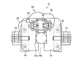
- FIG. 1 is a front view showing a schematic configuration of a target holding jig according to an embodiment of the present invention.
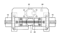
- FIG. 2 is a top view of the target holding jig shown in FIG.
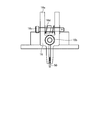
- FIG. 3 is a bottom view of the target holding jig shown in FIG.
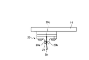
- FIG. 4 is a side view showing a schematic configuration of a connecting portion of the target holding jig shown in FIG.
- FIG. 5 is a cross-sectional view showing a schematic configuration viewed from the line AA in FIG.
- FIG. 6 is a cross-sectional view showing a schematic configuration viewed from the line BB in FIG.
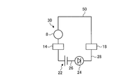
- FIG. 7 is a schematic diagram illustrating a circuit configuration of the detection unit.
- FIG. 1 is a front view showing a schematic configuration of a target holding jig according to an embodiment of the present invention.
- FIG. 2 is a top view of the target holding jig shown in FIG.
- FIG. 3 is a bottom view of the target holding
- FIG. 8 is a schematic diagram illustrating a schematic configuration of a measuring apparatus including a target holding jig.
- FIG. 9 is a perspective view illustrating a schematic configuration of a measurement object.
- FIG. 10 is a schematic diagram illustrating a positional relationship between the measurement object and the target holding jig during measurement.
- the target holding jig and the measuring device of the present invention will be described by taking an example of measuring the end surface on the inner peripheral side of the ring-shaped seal fin of the steam turbine. Is not limited to this.
- the target holding jig and the measuring device of the present invention can obtain a more remarkable effect when the seal fin is used as a measurement object.
- the position of the end face of the thin plate-like measurement object is measured. In this case, it can be suitably used.
- FIG. 1 is a front view showing a schematic configuration of a target holding jig according to an embodiment of the present invention.
- FIG. 2 is a top view of the target holding jig shown in FIG.
- FIG. 3 is a bottom view of the target holding jig shown in FIG.
- FIG. 4 is a side view showing a schematic configuration of a connecting portion of the target holding jig shown in FIG.
- FIG. 5 is a cross-sectional view showing a schematic configuration viewed from the line AA in FIG.
- FIG. 6 is a cross-sectional view showing a schematic configuration viewed from the line BB in FIG.
- FIG. 7 is a schematic diagram illustrating a circuit configuration of the detection unit.
- the target holding jig 10 holds the target 8 and is detachably connected to the measurement object 50.
- the target 8 is a part of a measuring apparatus described later, and includes a reflection mechanism that reflects measurement light.
- the target 8 is a substantially spherical member partially formed with a notch, and a reflector that reflects measurement light is provided in the notch.
- the measurement object 50 of the present embodiment is a ring-shaped seal fin of a steam turbine (hereinafter, the measurement object 50 is also referred to as a seal fin 50).
- the target holding jig 10 includes a support part 14, a connection part 16, a connection part 18, a guide part 20, a battery folder 22, a light emitting part 24, a wiring 26, and a wiring 28.
- the support portion 14 is a plate-like member, and is a member that becomes a base of the target holding jig 10.
- the support portion 14 has an opening 14a formed on the surface having the largest area (the surface facing the measurement object 50 when facing the measurement object (seal fin) 50 as shown in FIG. 1). Yes.
- the support portion 14 is formed with a notch 14 b that is connected to the opening 14 a and extends to the side surface of the support portion 14.
- this notch 14 b it is possible to secure a region where the measurement light enters and reflects on the target 8. Also for the user, since the notch 14b is formed, the relative position between the target 8 and the measurement object 50 can be easily confirmed through the notch 14b.
- the support unit 14 has a guide unit 20 disposed on a surface facing a measurement object (seal fin) 50, and a battery folder 22, a light emitting unit 24, A wiring 26 and a wiring 28 are arranged.
- the support part 14 has the connection part 16 and the connection part 18 arranged on each of a pair of side surfaces among the side surfaces sandwiched by the surface opposite to the surface facing the measurement object 50. Yes.
- positioned is a side surface in which the notch 14b is not formed.
- the support portion 14 is made of a conductive material such as metal.
- the support portion 14 is electrically connected to one electrode of the battery folder 22 and is electrically connected to the target 8. Furthermore, the connection part 16, the connection part 18, the wiring 26, the wiring 28, and the other member are electrically connected.
- the connecting part 16 and the connecting part 18 are mechanisms for connecting to the measurement object 50.
- the connecting portion 16 is disposed at one end portion of the support portion 14, and the connecting portion 18 is disposed at the other end portion of the support portion 14. That is, in the target holding jig 10, the connecting portion 16 and the connecting portion 18 are disposed at a position where the opening 14 a of the support portion 14 is sandwiched.
- the connecting portion 16 is fixed to the support portion 14 via the insulating portion 32.
- the connecting portion 18 is also fixed to the support portion 14 via the insulating portion 34.
- An insulating portion 32 is disposed at a fixed portion between the connecting portion 16 and the supporting portion 14, and an insulating portion 34 is disposed at a fixing portion between the connecting portion 18 and the supporting portion 14, thereby preventing electricity from flowing.
- the fixed part of the connection part 16 and the support part 14, and the fixed part of the connection part 18 and the support part 14 are being fixed by fastening mechanisms, such as a screw, maintaining the state which does not flow electricity.
- the target 8 inserted into the opening 14a is held at a predetermined position in the opening 14a by being in contact with the guide portion 20 and being sandwiched by the opening 14a. For this reason, the target 8 can be held in a direction in which the measurement light can be incident and reflected while being in contact with the measurement object by the guide portion 20.
- connection part 16 is a mechanism similar to what is called a clothespin, and has a clamping part 16a, a fulcrum 16b, a hinge pin 16c, and a spring 16d.
- the clamping part 16a is two members that rotate around the fulcrum 16b.
- the fulcrum 16b is connected to the connecting part 16, and supports the clamping part 16a in a rotatable state.
- the hinge pin 16c is inserted into a portion on the opposite side to the measurement object 50 side of the sandwiching portion 16a via a fulcrum 16b.
- the hinge pin 16c is configured not to be removed from the holding portion 16a by a retaining pin (not shown).
- the spring 16d is inserted into the hinge pin 16c and is disposed between the two members of the sandwiching portion 16a.
- the spring 16d pushes the two members of the clamping part 16a in the opening direction.
- the connecting portion 16 is formed on the measurement object 50 side of the sandwiching portion 16a by applying a force in a direction in which a portion opposite to the measurement object 50 side of the sandwiching portion 16a is opened by the spring 16d via the fulcrum 16b.
- the groove is narrowed. Thereby, the connection part 16 will be in the state connected with the measuring object 50 by pinching the measuring object 50 in a groove
- the connecting portion 16 may be formed with a concave / convex mechanism for preventing slippage or a member such as rubber at the end of the clamping portion 16a on the measuring object 50 side.
- the connection part 16 needs the function in which electricity flows between the measuring objects 50, and when providing rubber
- the mechanism of the connecting portion 16 and the connecting portion 18 is a mechanism for sandwiching the measurement object 50, but is not limited thereto.
- the target holding jig 10 may have a mechanism in which the connecting portion 16 and the connecting portion 18 are connected to the measurement object 50 by adsorption, such as a magnet.
- the guide portion 20 is disposed at a position on the same line as the connecting portion 16 and the connecting portion 18 on the surface of the support portion 14 facing the measurement object (seal fin) 50.
- the guide portion 20 is composed of two members extending along the same line, and a linear groove 21 is formed at a position on the same line as the groove formed in the holding portion of the connecting portion 16 and the connecting portion 18. ing.
- the target holding jig 10 can sandwich the measurement object 50 between the groove formed in the clamping part of the connecting part and the groove 21 of the guide part 20.
- the guide unit 20 is located at or near the position where the target 8 protrudes most toward the measurement object 50 as shown in FIG. 5. Can be brought into contact with the measurement object 50.
- the guide part 20 is made of an insulating material such as phenol resin.
- the guide portion 20 has a width that increases as the tip portion 20 a and the tip portion 20 b that are the tips of the groove 21 on the measurement object 50 side go to the measurement object 50 side. It becomes an inclined shape whose width becomes narrower as it goes to the support portion 14 side. Thereby, the guide part 20 becomes easy to insert the measuring object 50 in the groove
- two members constituting the guide unit 20 are detachable from the support unit 14 in the guide unit 20.
- a spacer 20 c is arranged in a region of the groove 21 where the measurement object 50 is not inserted.
- the guide part 20 mounts two members on the support part 14, the spacer 20c is disposed between the two members, whereby the width of the groove 21 can be set to the width of the spacer 20c.
- the guide part 20 can make the width
- the guide part 20 can change the width
- the interval between the grooves 21 is wider than the thickness of the measurement object 50.
- the battery folder 22 is installed on the support unit 14 and a battery (not shown) is attached. In the battery folder 22, one electrode is electrically connected to the support portion 14 and the other electrode is connected to the wiring 26.
- the light emitting unit 24 is installed on the support unit 14.
- the light emitting unit 24 is a light emitting diode or the like, and is an element that emits light when a current flows.
- the wiring 26 connects the other electrode of the battery folder 22 and the light emitting unit 24.
- the wiring 28 connects the light emitting unit 24 and the connecting unit 18.
- the target holding jig 10 becomes the detection unit 30 with the target 8, the support unit 14, the connection unit 18, the battery folder 22, the wiring 26, and the wiring 28.
- the detection unit 30 forms a single series circuit including the light emitting unit 24 and the measurement object 50.
- the detection unit 30 includes the target 8, the support unit 14, the connection unit 18, the battery folder 22, the wiring 26, and the wiring 28, and the target 8 and the support unit. 14, the battery folder 22, the wiring 26, the light emitting unit 24, the wiring 28, and the connecting unit 18 are connected in series in this order. Thereby, the detection part 30 will contact the connection part 18 and the measurement object 50, and if the target 8 and the measurement object 50 are contacted, the connection part 18, the measurement object 50, and the target 8 will be in series.
- the target holding jig 10 is configured as described above.
- the target 8 is supported by the support 14 and the measurement object 50 is sandwiched between the connection part 16, the connection part 18, and the guide part 20. 50.
- the target holding jig 10 can regulate the position of the measurement object 50 with the guide unit 20.
- the guide unit 20 sandwiches the measurement object 50, thereby restricting the position where the target 8 contacts the measurement object 50, and in the short side direction of the end surface of the measurement object 50 of the target 50. Restrict movement.
- the contact position between the measurement object 50 and the target 8 can be set within a predetermined range, and the displacement of the contact position between the measurement object 50 and the target 8 can be reduced. Therefore, the user can perform the measurement using the target 8 with high accuracy by using the target holding jig 10 of the present embodiment.
- the target holding jig 10 sandwiches the support portion 14 between the two connecting portions 16 and 18, and the extending direction of the groove 21 of the guide portion 20 is on a line connecting the connecting portion 16 and the connecting portion 18.
- the target holding jig 10 can determine whether the target 8 has surely contacted the measurement object 50 by the detection unit 30. Thereby, it can suppress measuring in the state where the measuring object 50 and the target 8 are not contacting, and it becomes possible to perform the measurement using the target 8 with high precision.
- the target holding jig 10 is configured such that the detection unit 30 is a circuit through which a current flows when the target 8 and the connecting unit 18 come into contact with the measurement object 50, so that the user attaches the target holding jig 10 to the measurement object 50. It is possible to detect whether the target 8 and the measuring object 50 are in contact with each other only by operating.
- the target 8 and the measurement object 50 are visually recognized by the user. Can be recognized as touching.
- the method of notifying the user that the target 8 and the measurement object 50 are in contact with each other by causing the light emitting unit 24 to emit light is not limited to light emission.
- the target holding jig 10 can use various mechanisms for transmitting to the user's five senses as a notification method.
- the target holding jig 10 may be provided with an audio output unit that emits sound instead of the light emitting unit 24.
- FIG. 8 is a schematic diagram illustrating a schematic configuration of a measuring apparatus including a target holding jig.
- FIG. 9 is a perspective view illustrating a schematic configuration of a measurement object.
- FIG. 10 is a schematic diagram illustrating a positional relationship between the measurement object and the target holding jig during measurement.
- the measuring apparatus 80 including the target holding jig 10 includes a target 8, a target holding jig 10, and a measuring apparatus main body 82.
- the target 8 is held by the target holding jig 10 and is in contact with the measurement object (seal fin) 50 by the target holding jig 10 at the time of measurement.
- the measuring device main body 82 includes a light source 82a, a light receiving unit 82b, and a processing unit 82c.
- the measuring apparatus main body 82 is provided with a head 84 and an optical system 86 that irradiate the measuring light toward the target 8 and guide the light reflected by the target 8 to the measuring apparatus main body 82.
- the light source 82a outputs the measurement light L.
- the light source 82a outputs, for example, laser light having a predetermined wavelength as the measurement light L.
- the light receiving unit 82b is a light receiving element that detects the reached light.
- the light receiving unit 82b detects light having the wavelength of the measurement light L.
- the processing unit 82c controls the operation of each unit of the measuring device 80. In addition, the processing unit 82c analyzes the detection result of the light receiving unit 82b and the information of the measurement light L output from the light source 82a, thereby measuring the distance to the target 8 and calculating the difference generated in the shape of the target 8. The distance to the measuring object 50 is measured by removing it by processing.
- the head 84 is disposed in a path through which the measurement light L output from the light source 82a passes, and adjusts the direction in which the measurement light L is irradiated.
- the optical system 86 is disposed between the light source 82 a and the head 84 and between the light receiving unit 82 b and the head 84, outputs the light output from the light source 82 a toward the head 84, and enters the head 84. The light is guided to the light receiving part 82b.
- the measuring device 80 installs the target holding jig 10 at the measurement position of the measurement object 50.
- the measurement object (seal fin) 50 of the present embodiment is installed in a seal ring 102 disposed inside the seal attachment ring 100 as shown in FIG.
- the seal fin 50 protrudes radially inward of the seal ring 102.
- a plurality of seal fins 50 are provided on the seal ring 102.
- the measuring device 80 is provided with a target holding jig 10 that holds the target 8 in the circumferential direction of the seal fins 50 arranged in a ring shape.
- the measurement device 80 outputs measurement light L from the measurement device main body 82 toward the target 8 via the head 84, and the light reflected by the target 8 via the head 84 is received by the measurement device main body 82 and received. By analyzing the result, the distance to the measurement object 50 can be measured. Further, the diameter of the seal fin 50 can be measured by moving the target holding jig 10 on the seal fin 50 and measuring a plurality of positions on the seal fin 50.
- the measurement object 50 is a seal fin as in the present embodiment, it is necessary to measure a large number of positions, but the target 8 is used as the measurement object 50 by using the detachable target holding jig 10.
- the target holding jig 10 is provided with the guide portion 20, so that the target 8 can be brought into contact with the measurement object 50 with high accuracy at the time of mounting. Furthermore, since the target holding jig 10 can notify the detection unit 30 and the light emitting unit 24 that the target 8 has contacted the measurement object 50, the user can easily install the target 8.
- Target 10 Target holding jig 14 Support portion 14a Opening 14b Notch 16, 18 Connection portion 16a Holding portion 16b Support point 16c Hinge pin 16d Spring 20 Guide portion 20a, 20b Tip portion 20c Spacer 21 Groove 22 Battery folder 24 Light emitting portion 26, 28 Wiring 32, 34 Insulation part 50 Seal fin (object to be measured) DESCRIPTION OF SYMBOLS 80 Measuring apparatus 82 Measuring apparatus main body 82a Light source 82b Light receiving part 82c Processing part 84 Head 86 Optical system 100 Seal mounting ring 102 Seal ring
Landscapes
- Physics & Mathematics (AREA)
- General Physics & Mathematics (AREA)
- Engineering & Computer Science (AREA)
- Radar, Positioning & Navigation (AREA)
- Remote Sensing (AREA)
- Computer Networks & Wireless Communication (AREA)
- Length Measuring Devices By Optical Means (AREA)
- Electromagnetism (AREA)
Abstract
Description
10 ターゲット保持冶具
14 支持部
14a 開口
14b 切欠き
16、18 連結部
16a 挟持部
16b 支点
16c ヒンジピン
16d バネ
20 ガイド部
20a、20b 先端部
20c スペーサ
21 溝
22 電池フォルダ
24 発光部
26、28 配線
32、34 絶縁部
50 シールフィン(測定対象物)
80 測定装置
82 測定装置本体
82a 光源
82b 受光部
82c 処理部
84 ヘッド
86 光学系
100 シール取付環
102 シールリング
Claims (7)
- 光源から射出された測定光を反射する反射機構を備える球状のターゲットを保持し、前記ターゲットと測定対象物の端面とを接触させるターゲット保持冶具であって、
前記測定対象物と接触させた状態で前記ターゲットを支持する支持部と、
前記支持部の前記測定対象物と対向する側に配置され、前記測定対象物の端面の短辺方向において前記ターゲットが前記測定対象物に接触する位置を規制し、かつ、前記ターゲットの前記測定対象物の端面の短辺方向への移動を規制するガイド部と、
前記支持部に固定され、前記測定対象物に着脱可能に連結する連結部と、を備えることを特徴とするターゲット保持冶具。 - 前記連結部は、前記測定対象物を挟持することで、前記測定対象物に連結することを特徴とする請求項1に記載のターゲット保持冶具。
- 前記ターゲットと前記測定対象物とが接触していることを検出する検出部と、
前記検出部が前記ターゲットと前記測定対象物との接触を検出したことを報知する報知部と、をさらに備えることを特徴とする請求項1または請求項2に記載のターゲット保持冶具。 - 前記検出部は、前記ターゲット及び前記連結部と接続された電源を有し、前記ターゲットと前記連結部と前記電源と前記報知部とが直列で接続され、
前記ターゲット及び前記連結部が前記測定対象物と接触すると、前記ターゲットと前記連結部と前記電源と前記報知部と前記測定対象物とが閉じられた回路となることを特徴とする請求項3に記載のターゲット保持冶具。 - 前記支持部と前記連結部との間に配置され、前記支持部と前記連結部とを絶縁する絶縁部をさらに有することを特徴とする請求項4に記載のターゲット保持冶具。
- 前記報知部は、発光する発光部であることを特徴とする請求項3から請求項5のいずれか一項に記載のターゲット保持冶具。
- 請求項1から請求項6のいずれか一項に記載のターゲット保持冶具と、
前記ターゲット保持冶具に保持されたターゲットと、
前記ターゲットに測定光を照射する光源と前記ターゲットで反射された測定光を受光する受光部と前記受光部で受光した結果を解析する処理部とを備える測定装置本体と、を有することを特徴とする測定装置。
Priority Applications (4)
| Application Number | Priority Date | Filing Date | Title |
|---|---|---|---|
| CN201480000943.2A CN104254756B (zh) | 2013-01-16 | 2014-01-10 | 觇板保持夹具及测定装置 |
| EP14740705.0A EP2908090B1 (en) | 2013-01-16 | 2014-01-10 | Target holding jig for optical measurements |
| US14/442,551 US9778347B2 (en) | 2013-01-16 | 2014-01-10 | Target holding jig and measurement apparatus |
| KR1020157012509A KR101538612B1 (ko) | 2013-01-16 | 2014-01-10 | 타깃 보유 지지 지그 및 측정 장치 |
Applications Claiming Priority (2)
| Application Number | Priority Date | Filing Date | Title |
|---|---|---|---|
| JP2013-005667 | 2013-01-16 | ||
| JP2013005667A JP5627719B2 (ja) | 2013-01-16 | 2013-01-16 | ターゲット保持冶具及び測定装置 |
Publications (1)
| Publication Number | Publication Date |
|---|---|
| WO2014112443A1 true WO2014112443A1 (ja) | 2014-07-24 |
Family
ID=51209533
Family Applications (1)
| Application Number | Title | Priority Date | Filing Date |
|---|---|---|---|
| PCT/JP2014/050361 WO2014112443A1 (ja) | 2013-01-16 | 2014-01-10 | ターゲット保持冶具及び測定装置 |
Country Status (6)
| Country | Link |
|---|---|
| US (1) | US9778347B2 (ja) |
| EP (1) | EP2908090B1 (ja) |
| JP (1) | JP5627719B2 (ja) |
| KR (1) | KR101538612B1 (ja) |
| CN (1) | CN104254756B (ja) |
| WO (1) | WO2014112443A1 (ja) |
Cited By (1)
| Publication number | Priority date | Publication date | Assignee | Title |
|---|---|---|---|---|
| CN114043402A (zh) * | 2021-11-08 | 2022-02-15 | 陕西飞机工业有限责任公司 | 数控调姿定位组件在飞机装配平台上的安装方法 |
Families Citing this family (5)
| Publication number | Priority date | Publication date | Assignee | Title |
|---|---|---|---|---|
| JP5908147B1 (ja) * | 2015-06-22 | 2016-04-26 | 三菱日立パワーシステムズ株式会社 | ターゲット保持冶具及び測定装置並びにターゲット保持方法 |
| CN111215887B (zh) * | 2019-12-04 | 2021-12-14 | 上海航天控制技术研究所 | 一种用于敏感包快速装配对准的防错式组合装置 |
| JP7445496B2 (ja) * | 2020-03-31 | 2024-03-07 | 三菱重工業株式会社 | フィン先端位置の計測方法、フィン先端位置の計測システム、及びフィン先端位置の計測用冶具 |
| CN111709500B (zh) * | 2020-06-01 | 2022-05-24 | 国网天津市电力公司电力科学研究院 | 一种输电铁塔紧固件服役异常的快速检测装置及方法 |
| CN112180335B (zh) * | 2020-09-29 | 2023-08-15 | 北京富奥星电子技术有限公司 | 一种多普勒雷达模组验证装置及验证方法 |
Citations (6)
| Publication number | Priority date | Publication date | Assignee | Title |
|---|---|---|---|---|
| JPH08219790A (ja) * | 1995-02-20 | 1996-08-30 | Hitachi Plant Eng & Constr Co Ltd | 反射板保持治具 |
| JPH10246635A (ja) * | 1997-02-28 | 1998-09-14 | Hitachi Kiden Kogyo Ltd | 三次元計測におけるレール測定用ターゲット |
| JPH11153438A (ja) * | 1997-11-21 | 1999-06-08 | Hitachi Plant Eng & Constr Co Ltd | 芯出治具及びそれを用いた測定装置 |
| JP2011039052A (ja) | 2009-08-07 | 2011-02-24 | Faro Technologies Inc | 光スイッチを備える絶対距離計 |
| JP2012137382A (ja) | 2010-12-27 | 2012-07-19 | Ihi Corp | 三次元計測治具及びこれを用いた三次元計測方法 |
| JP2012237661A (ja) * | 2011-05-12 | 2012-12-06 | Ntn Corp | 測定補助器具およびそれを用いた直径測定方法 |
Family Cites Families (7)
| Publication number | Priority date | Publication date | Assignee | Title |
|---|---|---|---|---|
| US5272814A (en) | 1989-04-14 | 1993-12-28 | Key Bruce G | Device for defining a horizontal plane |
| US6219931B1 (en) * | 1998-03-10 | 2001-04-24 | Northrop Grumman Corporation | Target base for a measuring system |
| ES2194748T3 (es) | 1999-07-28 | 2003-12-01 | Leica Geosystems Ag | Procedimiento y dispositivo destinados para la determinacion de posiciones y de orientaciones espaciales. |
| DE102008043977A1 (de) * | 2008-11-21 | 2010-06-10 | Airbus Deutschland Gmbh | Strukturelement für eine Rumpfzellenstruktur eines Flugzeugs |
| CN202281855U (zh) | 2011-10-08 | 2012-06-20 | 江阴香江光电仪器有限公司 | 金属单框棱镜组 |
| DE102011089837A1 (de) * | 2011-12-23 | 2013-06-27 | Hilti Aktiengesellschaft | Optisches System |
| CN104838234B (zh) * | 2013-09-19 | 2016-10-05 | 株式会社小松制作所 | 测定工具 |
-
2013
- 2013-01-16 JP JP2013005667A patent/JP5627719B2/ja active Active
-
2014
- 2014-01-10 EP EP14740705.0A patent/EP2908090B1/en active Active
- 2014-01-10 US US14/442,551 patent/US9778347B2/en active Active
- 2014-01-10 CN CN201480000943.2A patent/CN104254756B/zh active Active
- 2014-01-10 KR KR1020157012509A patent/KR101538612B1/ko active IP Right Grant
- 2014-01-10 WO PCT/JP2014/050361 patent/WO2014112443A1/ja active Application Filing
Patent Citations (6)
| Publication number | Priority date | Publication date | Assignee | Title |
|---|---|---|---|---|
| JPH08219790A (ja) * | 1995-02-20 | 1996-08-30 | Hitachi Plant Eng & Constr Co Ltd | 反射板保持治具 |
| JPH10246635A (ja) * | 1997-02-28 | 1998-09-14 | Hitachi Kiden Kogyo Ltd | 三次元計測におけるレール測定用ターゲット |
| JPH11153438A (ja) * | 1997-11-21 | 1999-06-08 | Hitachi Plant Eng & Constr Co Ltd | 芯出治具及びそれを用いた測定装置 |
| JP2011039052A (ja) | 2009-08-07 | 2011-02-24 | Faro Technologies Inc | 光スイッチを備える絶対距離計 |
| JP2012137382A (ja) | 2010-12-27 | 2012-07-19 | Ihi Corp | 三次元計測治具及びこれを用いた三次元計測方法 |
| JP2012237661A (ja) * | 2011-05-12 | 2012-12-06 | Ntn Corp | 測定補助器具およびそれを用いた直径測定方法 |
Non-Patent Citations (1)
| Title |
|---|
| See also references of EP2908090A4 |
Cited By (1)
| Publication number | Priority date | Publication date | Assignee | Title |
|---|---|---|---|---|
| CN114043402A (zh) * | 2021-11-08 | 2022-02-15 | 陕西飞机工业有限责任公司 | 数控调姿定位组件在飞机装配平台上的安装方法 |
Also Published As
| Publication number | Publication date |
|---|---|
| EP2908090A4 (en) | 2015-11-18 |
| US9778347B2 (en) | 2017-10-03 |
| EP2908090B1 (en) | 2017-03-08 |
| US20160291133A1 (en) | 2016-10-06 |
| KR101538612B1 (ko) | 2015-07-21 |
| JP2014137273A (ja) | 2014-07-28 |
| CN104254756A (zh) | 2014-12-31 |
| JP5627719B2 (ja) | 2014-11-19 |
| KR20150056882A (ko) | 2015-05-27 |
| CN104254756B (zh) | 2015-11-25 |
| EP2908090A1 (en) | 2015-08-19 |
Similar Documents
| Publication | Publication Date | Title |
|---|---|---|
| WO2014112443A1 (ja) | ターゲット保持冶具及び測定装置 | |
| US7027160B2 (en) | Device and method for measuring transmission and reflection properties of objects and surfaces | |
| JP2014137273A5 (ja) | ||
| JP2006030135A (ja) | 光学特性測定装置 | |
| KR20100043969A (ko) | 거리 측정 장치 | |
| US20130050690A1 (en) | Calibration device for light measuring equipment | |
| CN107430001B (zh) | 靶保持夹具、测定装置及靶保持方法 | |
| US9146091B2 (en) | Displacement measurement apparatus and displacement measurement method | |
| JP2015014484A (ja) | レール断面形状測定装置 | |
| WO2012124208A1 (ja) | 発光装置、情報取得装置およびこれを搭載する物体検出装置 | |
| TWI573990B (zh) | 測定裝置及控制方法 | |
| JP5066401B2 (ja) | 定点検出装置及び変位測定装置 | |
| JP6248645B2 (ja) | パイプ液体検出センサ | |
| JP2017032378A (ja) | センサ装置 | |
| JP2009271012A (ja) | 厚さ測定装置の距離センサの位置調整方法 | |
| JP2006194737A (ja) | 光学検査機器 | |
| CN218247100U (zh) | 光学测量模块、激光雷达以及机器人 | |
| KR20100044079A (ko) | 경사 검출기 및 레이저 마킹기 | |
| JP2019132704A (ja) | ターゲット保持治具、測定装置及び測定方法 | |
| JP2016189893A (ja) | 脈波検出装置 | |
| JP2005172462A (ja) | 光学式測定装置 | |
| JP2008232970A (ja) | 変位測定器 | |
| JP5734484B2 (ja) | 変位計測装置及び変位計測方法 | |
| JP2019133536A (ja) | 炎感知器用試験装置 | |
| WO2015194025A1 (ja) | 光学部品駆動装置及び光学部品駆動方法 |
Legal Events
| Date | Code | Title | Description |
|---|---|---|---|
| 121 | Ep: the epo has been informed by wipo that ep was designated in this application |
Ref document number: 14740705 Country of ref document: EP Kind code of ref document: A1 |
|
| ENP | Entry into the national phase |
Ref document number: 20157012509 Country of ref document: KR Kind code of ref document: A |
|
| REEP | Request for entry into the european phase |
Ref document number: 2014740705 Country of ref document: EP |
|
| WWE | Wipo information: entry into national phase |
Ref document number: 14442551 Country of ref document: US Ref document number: 2014740705 Country of ref document: EP |
|
| NENP | Non-entry into the national phase |
Ref country code: DE |