WO2014108996A1 - 耐圧容器用ダイカスト製品の製造方法 - Google Patents
耐圧容器用ダイカスト製品の製造方法 Download PDFInfo
- Publication number
- WO2014108996A1 WO2014108996A1 PCT/JP2013/050101 JP2013050101W WO2014108996A1 WO 2014108996 A1 WO2014108996 A1 WO 2014108996A1 JP 2013050101 W JP2013050101 W JP 2013050101W WO 2014108996 A1 WO2014108996 A1 WO 2014108996A1
- Authority
- WO
- WIPO (PCT)
- Prior art keywords
- molten metal
- mold
- die
- cast product
- pressure
- Prior art date
- Legal status (The legal status is an assumption and is not a legal conclusion. Google has not performed a legal analysis and makes no representation as to the accuracy of the status listed.)
- Ceased
Links
Images


Classifications
-
- B—PERFORMING OPERATIONS; TRANSPORTING
- B22—CASTING; POWDER METALLURGY
- B22D—CASTING OF METALS; CASTING OF OTHER SUBSTANCES BY THE SAME PROCESSES OR DEVICES
- B22D17/00—Pressure die casting or injection die casting, i.e. casting in which the metal is forced into a mould under high pressure
-
- B—PERFORMING OPERATIONS; TRANSPORTING
- B22—CASTING; POWDER METALLURGY
- B22D—CASTING OF METALS; CASTING OF OTHER SUBSTANCES BY THE SAME PROCESSES OR DEVICES
- B22D17/00—Pressure die casting or injection die casting, i.e. casting in which the metal is forced into a mould under high pressure
- B22D17/20—Accessories: Details
- B22D17/22—Dies; Die plates; Die supports; Cooling equipment for dies; Accessories for loosening and ejecting castings from dies
-
- B—PERFORMING OPERATIONS; TRANSPORTING
- B22—CASTING; POWDER METALLURGY
- B22D—CASTING OF METALS; CASTING OF OTHER SUBSTANCES BY THE SAME PROCESSES OR DEVICES
- B22D27/00—Treating the metal in the mould while it is molten or ductile ; Pressure or vacuum casting
- B22D27/006—Treating the metal in the mould while it is molten or ductile ; Pressure or vacuum casting by using reactive gases
Definitions
- the present invention relates to a method for manufacturing a die-cast product for a pressure vessel.
- the die casting method is known as a kind of casting method.
- a molten metal such as an aluminum alloy is press-fitted into an inner space (cavity) of a mold.
- a pore-free die casting method (non-porous die casting method) is known as a die casting method for preventing gas entrainment (see Patent Documents 1 and 2).
- the pore-free die casting method is to fill an internal space of a mold with an active gas such as oxygen at a pressure higher than atmospheric pressure, and press the molten metal into the mold in such a state. According to the pore-free die casting method, since the active gas in the mold reacts with the molten metal, the gas entrained in the molten metal decreases.
- the appropriate thickness of the die-cast product is 2 to 4 mm.
- the thickness of the die-cast product exceeds 7 mm, shrinkage cavities become apparent, so that the die-casting method is not suitable for products having a thick portion.
- a pressure vessel for example, a hydraulic cylinder, an air cylinder, etc.
- a smooth surface surface that slides in contact with the piston
- a seal groove a thick portion of a shape material that becomes the element of the pressure vessel Since it is necessary to perform surface cutting or grooving, the thickness of the shaped material needs to be set in consideration of a cutting allowance or the like.
- the thickness of the raw material varies depending on the use of the pressure vessel and the size of the pressure, but may be a size not suitable for the die casting method.
- machining such as surface cutting and grooving is performed on the casting surface of the die-cast product, but if the machining allowance increases, the product after machining Entrapment nests and shrinkage nests may be exposed on the surface. In particular, if there is a large entrapment nest or shrinkage nest that straddles the seal groove, the sealing performance may be impaired.
- an object of the present invention is to provide a method for manufacturing a die-cast product for a pressure resistant container in which a large entrainment nest and a shrinkage nest are difficult to be formed in a thick part including a region where the machining allowance is maximized.
- the present invention is a method of manufacturing a die-cast product for a pressure vessel having a thick part including a region where the machining allowance is maximized, and an inner space of a mold for molding the die-cast product for a pressure vessel Including an active gas filling process in which the active gas is filled at a pressure equal to or higher than atmospheric pressure, and a melt press-in process for injecting the melt into the internal space from at least one gate provided in the mold, in the melt press-in process, The molten metal is ejected from at least one of the gates toward a mold part for forming the thick part, and the molten metal is hit against the mold part.
- the present invention uses the pore-free die casting method.
- the active gas in the mold reacts with the molten metal to become a fine solid, and the active gas remaining in the mold disappears, so that the gas trapped in the molten metal is reduced.
- the thick part of the die-cast product (the part including the region where the cutting allowance is maximized) is formed by hitting the molten metal against the mold part so that the molten metal is refined into a mist or splash in the mold.
- the reaction between the active gas and the molten metal is promoted, and the amount of gas causing the entrapment nest can be reduced.
- the portion of the inner space of the mold that is not filled with the molten metal is close to a vacuum, the molten metal can be filled quickly to every corner of the mold, and the molten metal and the mold are in close contact with each other. Good.
- the molten metal that is in close contact with the mold is efficiently cooled, and the molten metal that has collided with the mold is dispersed in the form of mist and droplets and is cooled and solidified, so that a fine cast structure with few cast holes is obtained.
- the present invention even when residual gas exists around the region where the cutting allowance is maximum, it is dispersed independently with small bubbles, so that it is difficult to form a large entrainment nest.
- an internal defect that straddles the seal groove hardly appears.
- a cast-out part (a mold for forming a hole or a chipped part in the thick-walled part) is arranged in the space that becomes the thick-walled part, the molten metal is ejected toward the cast-out part, The molten metal may be hit against the surface of the part.
- the molten metal filled in the space that becomes the thick wall part hits the surface of the cast part, it is refined into a mist or droplet, and it is dispersed and quickly solidified while being cooled. It is possible to suitably and independently disperse the entrainment nests.
- the mold part (the mold part where the molten metal collides with the mold). If it does in this way, the molten metal which collided with the said mold part comes to solidify more rapidly.
- the generation of the shrink nest can be effectively suppressed.
- a water-soluble release agent diluted with water attached to the mold.
- the water-soluble release agent is preferably a silicon oil-based water-soluble release agent or a graphite-based water-soluble release agent.
- the present invention it becomes difficult to form a large entrainment nest and shrinkage nest in the thick part of the die-cast product for a pressure vessel, so even if the thick part is subjected to surface processing or groove processing, the performance of the pressure vessel is hindered. Such internal defects are less likely to appear, and as a result, the yield can be improved.
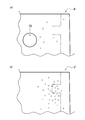
- FIG. 3 is a cross-sectional view taken along line X2-X2 of FIG. BRIEF DESCRIPTION OF THE DRAWINGS It is the figure which represented typically the mode of the entrapment nest in the die-cast product for pressure vessels, (a) is the die-cast product for pressure vessels obtained by the manufacturing method of the die-cast product for pressure vessels which concerns on embodiment of this invention.
- (B) is an expanded sectional view of the die-cast product for pressure-resistant containers obtained by the manufacturing method concerning a comparative example.
- a die-cast product for a pressure vessel (hereinafter referred to as “die-cast product D”) obtained by the manufacturing method according to the embodiment of the present invention is a material made of an aluminum alloy, which is a base of a hydraulic cylinder, an air cylinder, or other pressure vessel. is there. As shown in FIG. 1, the die-cast product D has a bottomed cylindrical space V1.
- the die-cast product D includes a surface layer 1 facing the cylindrical space V1 and a main body 2 positioned outside the surface layer 1.
- the thickness of the die-cast product D exceeds 2 to 4 mm, which is a general application range of the die casting method, and the thinnest part is 7 mm or more. That is, in this embodiment, the whole die-cast product D is a thick part.
- the cylindrical space V ⁇ b> 1 has a shape in which the inner diameter gradually decreases from the opening end toward the bottom due to the draft gradient provided in the mold.
- Surface layer 1 is a cutting allowance (finishing allowance) cut by cutting.
- the surface layer 1 of the present embodiment includes a cylindrical region 1a and a disc-like region 1b that are excised by surface cutting, and a ring-like region 1c that is excised by grooving after the surface cutting.
- the cylindrical region 1a is a portion corresponding to the peripheral wall (inner peripheral surface) of the columnar space V1, and has a shape in which the thickness gradually increases from the opening end of the columnar space V1 toward the bottom.
- the surface of the main body 2 that appears after the cylindrical region 1a is excised becomes a sliding surface that is in sliding contact with the outer peripheral surface of a piston (not shown).
- the disc-shaped region 1b is a portion corresponding to the bottom wall (bottom surface) of the cylindrical space V1.
- the thickness of the disc-shaped region 1b is smaller than the thickness of the cylindrical region 1a.
- region 1b becomes unnecessary.
- the ring-shaped region 1c is a region having a rectangular cross section provided on the outer peripheral side of the cylindrical region 1a.
- the ring-shaped region 1c is provided in the vicinity of the opening end of the columnar space V1, and is continuous in the circumferential direction of the columnar space V1.
- a groove having a rectangular cross section that appears after the ring-shaped region 1c is cut off becomes a seal groove.
- An annular seal material (not shown) that contacts the outer peripheral surface of the piston (not shown) is fitted into the seal groove.
- the thickness of the surface layer 1 (distance from the inner peripheral surface of the ring-shaped region 1c to the main body 2) on the virtual plane having the normal to the central axis of the columnar space V1 is determined when the virtual plane passes through the ring-shaped region 1c.
- the region where the machining allowance is maximum (hereinafter referred to as “the maximum machining allowance region”) is a region where the ring-shaped region 1c and the cylindrical region 1a adjacent to the inner periphery thereof are combined. cash on t 1 cutting in cutting cash maximum area is greater than the cutting cash t 2 in the lower part of the cylindrical region 1a.
- the main body 2 is a portion remaining after the surface layer 1 is cut.
- the main body 2 of the present embodiment includes a cylinder side portion 2a formed on the outer peripheral side of the cylindrical region 1a, and a cylinder bottom portion 2b formed on the outer side (lower side in FIG. 1B) of the disc-like region 1b. And overhanging portions 2c, 2c projecting sideways from the outer peripheral surface of the cylinder side portion 2a, and a gate 2d protruding from the overhanging portion 2c.
- the cylinder side part 2a is a part that becomes a peripheral wall of the cylinder (a peripheral wall of the columnar space V1 after cutting the surface layer 1), and surrounds the columnar space V1 on the outer peripheral side of the cylindrical region 1a.
- the outer peripheral surface of the cylinder side portion 2a is a tapered surface.
- the outer diameter of the tapered surface is gradually reduced from the opening end side of the cylindrical space V1 toward the cylinder bottom 2b.
- the outer peripheral surface of the cylinder side portion 2a is a tapered surface, but may be changed as appropriate.
- the cylinder bottom portion 2b is a portion that becomes the bottom wall of the cylinder (the bottom wall of the cylindrical space V1 after the surface layer 1 is cut), and is formed outside the disc-shaped region 1b (lower side in FIG. 1B). Has been.
- a cavity V2 is formed in the overhang portion 2c.
- the illustrated overhang portion 2c has a rectangular parallelepiped shape, but is not intended to limit the shape of the overhang portion 2c.
- the pair of overhang portions 2c and 2c are arranged on both sides of the columnar space V1, but the position and number of the overhang portions 2c may be changed as appropriate, or the cylinder side You may form continuously over the perimeter of the part 2a.
- the gate part 2d is a surplus part inevitably formed in the gate of the mold.
- the gate 2d of the present embodiment protrudes from the lower surface (surface on the cylinder bottom 2b side) of the overhang portion 2c.
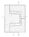
- the cavity V2 is formed at the time of casting using the cast-out part 5 (see FIG. 2).
- one cavity V2 is provided for one overhanging portion 2c, but the number and arrangement of the cavities V2 may be changed.
- the manufacturing method of the die-cast product D uses a pore-free die casting method, and includes a preparation process, an active gas filling process, and a molten metal press-fitting process.
- the mold (fixed mold 3A, movable mold 3B, core 4) includes an internal space (gavity) C corresponding to the die-cast product D.
- the maximum machining allowance region (a region obtained by combining the ring-shaped region 1c and the cylindrical region 1a adjacent to the inner periphery thereof) is located above the internal space C, and the disc-shaped region 1b Located at the bottom of.
- Pin gates 31 and 31 communicating with the internal space C are provided on a mating surface (divided surface) between the fixed mold 3A and the movable mold 3B.
- the fixed mold 3A and the movable mold 3B are for molding the outer peripheral surface and the lower surface of the die-cast product D.
- the core 4 is for molding the opening end face of the die-cast product D, the peripheral wall and the bottom wall of the cylindrical space V1 (see FIG. 1).
- the corner portion 4a of the core 4 (the portion for forming the peripheral wall on the opening end side of the cylindrical space V1 and the opening end surface of the die cast product D connected thereto) is close to the maximum machining allowance region.
- the cast-out part 5 forms the cavity V ⁇ b> 2 and is disposed in the vicinity of the corner part 4 a of the core 4.
- the fixed mold 3A, the movable mold 3B, the core 4 and the cast part 5 include a water cooling pipe for cooling the mold surface, an air vent for discharging the active gas outside the mold, and the like. Is formed.
- the pin gate 31 is opened to a position where the corner portion 4a of the core 4 and at least one cast-out portion 5 can be seen (in this embodiment, the surface of the mold for molding the lower surface of the overhang portion 2c). Yes. That is, the virtual line segments P1 and P2 extending from one pin gate 31 to the corner 4a of the core 4 and the virtual line segment Q extending from one pin gate 31 to any one of the punched portions 5 are made of other gold. It passes through the internal space C without being blocked by the mold part.
- the preparation process is a process of applying a water-soluble release agent diluted with water to the mold.
- the water-soluble release agent is preferably a silicon oil-based water-soluble release agent or a graphite-based water-soluble release agent. 2 and 3 illustrate the state in which the mold is clamped, but the operation of applying the water-soluble release agent is performed in a state where the mold is opened and after the water-soluble release agent is applied. Tighten the mold.
- the active gas filling process is a process in which the internal space C of the mold is filled with the active gas at a pressure higher than atmospheric pressure. If the internal space C of the mold is set to atmospheric pressure or higher, the intrusion of the atmosphere can be prevented.
- the active gas in this embodiment is oxygen.
- the molten metal press-fitting process is a process in which a molten aluminum alloy is press-fitted (injected) into the internal space C from the pin gates 31 and 31.
- the molten metal in contact with the mold surface quickly solidifies, and the active gas (oxygen) in the internal space C reacts with part of the molten metal to become an oxide (Al 2 O 3 ).
- the molten metal is ejected from the pin gates 31 and 31 toward the mold part (the inner corner part 4a of the core 4 or the cast part 5) for forming a thick part including the maximum machining allowance region.
- the molten metal is hit against the mold part.
- the molten metal ejection speed from the pin gate 31 is set to 80 to 120 m / sec.
- the amount of gas causing the entrapment nest can be reduced.
- the portion of the inner space C of the mold that is not filled with the molten metal is close to a vacuum, the molten metal can be filled quickly to every corner of the mold, and the molten metal and the mold Adhesion is improved and the molten metal can be cooled efficiently.
- the molten metal is cooled by colliding with the cooled mold, it quickly solidifies, and as a result, a fine cast structure with few cast holes is obtained.
- the active gas in the mold reacts with the molten metal, so that the gas entrained in the molten metal decreases.
- the molten metal when struck against the surface of the core corner 4a or the punched portion 5 of the core 4, the molten metal becomes finer in a mist or droplet shape in the region including the maximum machining allowance region.
- the reaction of the active gas therein is promoted, and as a result, the entrapment nest is hardly formed around the maximum machining allowance region (see FIG. 3A).
- the mold Even if the mold is filled with active gas, it is not possible to replace all of the air in the mold and the water vapor coming out of the mold release agent, so a slight amount of inert gas remains in the mold. To do. The remaining inert gas becomes an entrapment nest, and the entrapment nest cannot be made zero.
- the die-cast product D the number of entrapment nests appearing on the surface after cutting is reduced, and since it becomes an independent entrapment nest, a large internal defect straddling the seal groove is less likely to appear. Even when the treatment is omitted, high air tightness and liquid tightness can be ensured.
- the pin gates 31 and 31 are communicated with the lower part of the internal space C of the mold and the molten metal is sprayed upward, the molten metal refined in the form of mist or droplets is the whole thick part. It becomes easy to spread. That is, the reaction between the active gas and the molten metal is promoted throughout the thick-walled portion, and as a result, the amount of gas causing the entrapment nest can be reduced.
- the configuration of the mold may be changed as appropriate according to the shape and size of the die-cast product D.
- the number of pin gates 31 is two, but may be appropriately changed according to the shape and size of the die-cast product D.
- illustration is abbreviate
- a pin gate that can see through at least one of the corner portion 4 a of the core 4 and the cast-out portion 5 may be provided.
Landscapes
- Engineering & Computer Science (AREA)
- Mechanical Engineering (AREA)
- Molds, Cores, And Manufacturing Methods Thereof (AREA)
- Mold Materials And Core Materials (AREA)
Abstract
本発明は、削り代が最大となる領域を包含する厚肉部に大きな巻き込み巣と引け巣が形成され難い耐圧容器用ダイカスト製品の製造方法を提供することを課題とするものである。 削り代が最大となる領域を包含する厚肉部を有する耐圧容器用ダイカスト製品(D)を製造する方法であって、耐圧容器用ダイカスト製品(D)を成形するための金型の内部空間(C)に大気圧以上の圧力で活性ガスを充満させる活性ガス充填過程と、金型に設けたピンゲート(31,31)から内部空間(C)に溶湯を圧入する溶湯圧入過程とを含み、溶湯圧入過程では、厚肉部を成形するための金型部分(4a,5)に向けてピンゲート(31,31)から溶湯を噴出させ、金型部分(4a,5)に溶湯をぶつけることを特徴とする。
Description
本発明は、耐圧容器用ダイカスト製品の製造方法に関する。
鋳造方法の一種として、ダイカスト法が知られている。ダイカスト法は、アルミニウム合金等の溶湯を金型の内部空間(キャビティ)に圧入する、というものである。
金型内部に充満しているガス(空気、水蒸気等)は、溶湯の圧入によって大半が金型の内部空間から排出されるが、金型内に残留するものもある。金型内に残留したガスは、溶湯に巻き込まれ、巻き込み巣(巻き込まれたガスにより生じる鋳巣)の原因となる。大きな巻き込み巣を内包したダイカスト製品に熱処理を施すと、ガスの膨張に起因してダイカスト製品にブリスター(膨れ)が発生する場合もある。
ガスの巻込みを防止するダイカスト法として、ポアフリーダイカスト法(無孔性ダイカスト法)が知られている(特許文献1,2参照)。ポアフリーダイカスト法は、大気圧以上の圧力で酸素等の活性ガスを金型の内部空間に充満させ、かかる状態で金型内に溶湯を圧入する、というものである。ポアフリーダイカスト法によれば、金型内の活性ガスが溶湯と反応するので、溶湯に巻き込まれるガスが減少するようになる。
なお、ダイカスト製品の肉厚は、2~4mmが適当とされている。ダイカスト製品の肉厚が7mmを超えると、引け巣が顕在化するようになることから、ダイカスト法は、厚肉部を有する製品には不向きとされている。
ところで、耐圧容器(例えば、油圧シリンダ、エアシリンダなど)を製造する場合には、平滑面(ピストンに摺接する面)やシール溝を得るべく、耐圧容器の素となる素形材の厚肉部に表面切削や溝加工を施す必要があるので、前記素形材の肉厚は、削り代等を考慮して設定する必要がある。素形材の肉厚の大きさは、耐圧容器の用途や圧力の大きさによって異なるが、ダイカスト法に適していない大きさになることもある。
ダイカスト製品を耐圧容器の素形材とする場合には、ダイカスト製品の鋳肌に対して表面切削や溝加工等の機械加工を施すことになるが、削り代が大きくなると、機械加工後の製品表面に巻き込み巣や引け巣が露出する可能性がある。特に、シール溝を跨ぐような大きな巻き込み巣または引け巣が存在すると、シール性が損なわれる虞がある。
このような観点から、本発明は、削り代が最大となる領域を包含する厚肉部に大きな巻き込み巣と引け巣が形成され難い耐圧容器用ダイカスト製品の製造方法を提供することを課題とする。
本願発明者は、ダイカスト製品で耐圧容器を形成すべく鋭意研究を行った結果、厚肉部に大きな巻き込み巣と引け巣が形成され難い耐圧容器用ダイカスト製品の製造方法を見出すに至った。
すなわち、本発明は、削り代が最大となる領域を包含する厚肉部を有する耐圧容器用ダイカスト製品を製造する方法であって、前記耐圧容器用ダイカスト製品を成形するための金型の内部空間に大気圧以上の圧力で活性ガスを充満させる活性ガス充填過程と、前記金型に設けた少なくとも一つのゲートから前記内部空間に溶湯を圧入する溶湯圧入過程とを含み、前記溶湯圧入過程では、前記厚肉部を成形するための金型部分に向けて少なくとも一つの前記ゲートから溶湯を噴出させ、前記金型部分に溶湯をぶつけることを特徴とする。
すなわち、本発明は、削り代が最大となる領域を包含する厚肉部を有する耐圧容器用ダイカスト製品を製造する方法であって、前記耐圧容器用ダイカスト製品を成形するための金型の内部空間に大気圧以上の圧力で活性ガスを充満させる活性ガス充填過程と、前記金型に設けた少なくとも一つのゲートから前記内部空間に溶湯を圧入する溶湯圧入過程とを含み、前記溶湯圧入過程では、前記厚肉部を成形するための金型部分に向けて少なくとも一つの前記ゲートから溶湯を噴出させ、前記金型部分に溶湯をぶつけることを特徴とする。
本発明は、ポアフリーダイカスト法を利用するものである。ポアフリーダイカスト法を利用すると、金型内の活性ガスが溶湯と反応して微細な固体となり、金型内に残留する活性ガスが無くなるので、溶湯に巻き込まれるガスが減少するようになる。
また、金型部分に溶湯をぶつけて金型内で溶湯が霧状または飛沫状に微細化するようにして、ダイカスト製品の厚肉部(削り代が最大となる領域を包含する部分)を成形する金型部分に溶湯を導入すると、活性ガスと溶湯との反応が促進され、巻き込み巣の原因となるガス量を減少させることができる。さらに、金型の内部空間のうちの溶湯で満たされていない部分が真空に近い状態になるので、溶湯が金型の隅々まで素早く満たされるようになり、かつ、溶湯と金型との密着性が良好になる。金型に密着した溶湯が効率良く冷却され、かつ、金型にぶつかった溶湯が霧状・飛沫状に分散すると共に冷却され凝固するので、鋳巣の少ない微細な鋳造組織が得られる。
金型内に活性ガスを充満させたとしても、金型内の空気や離型剤から出てくる水蒸気の全てを置換することはできないので、金型内に不活性ガスが僅かに残留する。残留した不活性ガスは巻き込み巣となるので、巻き込み巣をゼロにすることはできないが、前記のとおり、金型の内部空間が真空に近い状態になる結果、溶湯が金型の隅々まで素早く満たされ、かつ、金型との密着性が良好となる。さらに、溶湯は、金型にぶつかって冷却されているので、厚肉部となる空間に充填された溶湯は、速やかに凝固するようになる。このように、本発明によれば、溶湯が分散し速やかに凝固するので、溶湯に巻き込まれた気泡が溶湯中を漂っている時間は極めて短いものとなり、したがって、溶湯中に分散していた気泡が厚肉部に集合する(=巻き込み巣が大きくなる)こともない。つまり、本発明によれば、削り代が最大となる領域の周囲に残留ガスが存在した場合であっても、小さな気泡のまま独立して分散するようになるので、大きな巻き込み巣が形成され難くなり、例えば削り代が最大となる領域を切削してシール溝を形成しても、シール溝を跨ぐような内部欠陥が出現し難くなる。なお、耐圧容器用ダイカスト製品の肉厚が7mm以上となると、凝固収縮による引け巣の発生が懸念されるが、僅かに残った巻き込み巣の内部には、高圧のガスが残留しているので、凝固収縮に見合う程度に巻き込み巣を微細分散させていると、引け巣の発生を抑制することができる。
前記厚肉部となる空間に鋳抜き部(厚肉部に穴や欠損部を形成するための金型)を配置した場合には、当該鋳抜き部に向けて溶湯を噴出し、当該鋳抜き部の表面に溶湯をぶつけてもよい。厚肉部となる空間に充填された溶湯が鋳抜き部の表面にぶつかると、霧状または飛沫状に微細化し、冷却されつつ分散して速やかに凝固するようになるので、厚肉部に形成される巻き込み巣を好適に独立して分散させることが可能となる。
前記金型部分(金型のうち、溶湯がぶつかる金型部分)を冷却するとよい。このようにすると、当該金型部分にぶつかった溶湯がより速やかに凝固するようになる。
なお、前記したとおり、巻き込み巣を適度に分散させると、引け巣の発生を効果的に抑制することができる。巻き込み巣を適度に発生させるためには、水で希釈した水溶性離型剤を前記金型に付着させた状態で、前記内部空間に溶湯を圧入するとよい。水溶性離型剤は、シリコンオイル系水溶性離型剤又は黒鉛系水溶性離型剤が好適である。
水で希釈した水溶性離型剤を使用すると、金型に付着した離型剤中の水(H2O)の一部が金型の熱と溶湯の熱によって水蒸気になるが、ポアフリーダイカスト法では、金型の内部空間内の活性ガスの酸素と溶湯とが優先して反応することによって溶湯の表面に常に酸化膜が形成されるので、酸素より安定物質の水蒸気中の水(H2O)と溶湯との反応が起こり難い状況にあり、その結果、水蒸気が小さな気泡のままダイカスト製品内に分散するものと解される。このように、水で希釈した水溶性離型剤を使用すると、水蒸気に起因した巻き込み巣が適度に発生するようになるので、引け巣を抑制することが可能となる。なお、水(H2O)の一部は溶湯と反応するが、溶湯と反応した水は、固体である酸化物と、固溶した水素とになる。凝固時に水素の溶解度が減少して水素ガスが生成するが、凝固速度が速いので、顕微鏡でも見えない位の小さな気泡となり、大きな気泡にはならない。
本発明によれば、耐圧容器用ダイカスト製品の厚肉部に大きな巻き込み巣と引け巣が形成され難くなるので、厚肉部に表面加工や溝加工を施しても、耐圧容器の性能を阻害するような内部欠陥が出現し難くなり、ひいては、歩留まりを向上させることが可能となる。
本発明の実施形態に係る製造方法によって得られる耐圧容器用ダイカスト製品(以下「ダイカスト製品D」という。)は、油圧シリンダ、エアシリンダその他の耐圧容器の素となるアルミニウム合金製の素形材である。図1に示すように、ダイカスト製品Dには、有底の円柱状空間V1が形成されている。
ダイカスト製品Dは、円柱状空間V1に面する表層1と、表層1の外側に位置する本体2とを備えている。ダイカスト製品Dの肉厚は、ダイカスト法の一般的な適用範囲である2~4mmを超えており、最も薄い部分でも7mm以上である。つまり、本実施形態では、ダイカスト製品Dの全体が厚肉部となっている。円柱状空間V1は、金型に設けた抜け勾配の関係で、開口端から底部に向かうに従って内径が漸減する形状となっている。
表層1は、切削加工によって切除される削り代(仕上げ代)である。本実施形態の表層1は、表面切削加工によって切除される円筒状領域1aおよび円板状領域1bと、表面切削加工後の溝加工によって切除されるリング状領域1cとを備えている。
円筒状領域1aは、円柱状空間V1の周壁(内周面)に相当する部位であり、円柱状空間V1の開口端から底部に向かうに従って肉厚が漸増する形状となっている。円筒状領域1aを切除した後に出現する本体2の表面は、ピストン(図示略)の外周面に摺接する摺動面となる。
円板状領域1bは、円柱状空間V1の底壁(底面)に相当する部位である。円板状領域1bの肉厚は、円筒状領域1aの肉厚よりも小さくなっている。なお、円柱状空間V1の底部を鋳肌のまま残す場合には、円板状領域1bは不要となる。
リング状領域1cは、円筒状領域1aの外周側に設けられた断面矩形状の領域である。リング状領域1cは、円柱状空間V1の開口端付近に設けられていて、円柱状空間V1の周方向に連続している。リング状領域1cを切除した後に出現する断面矩形状の溝は、シール溝となる。シール溝には、ピストン(図示略)の外周面に接する環状のシール材(図示略)が嵌め込まれる。
円柱状空間V1の中心軸線を法線とする仮想平面上における表層1の肉厚(リング状領域1cの内周面から本体2までの距離)は、当該仮想平面がリング状領域1cを通るときに最大となる。つまり、ダイカスト製品Dにおいて削り代が最大となる領域(以下「削り代最大領域」という。)は、リング状領域1cとその内周側に隣接する円筒状領域1aとを合わせた領域であり、削り代最大領域における削り代t1は、円筒状領域1aの下部における削り代t2よりも大きい。
本体2は、表層1を切削した後に残る部位である。本実施形態の本体2は、円筒状領域1aの外周側に形成されたシリンダ側部2aと、円板状領域1bの外側(図1の(b)において下側)に形成されたシリンダ底部2bと、シリンダ側部2aの外周面から側方に向かって張り出す張出部2c,2cと、張出部2cに突設された湯口部2dとを備えている。
シリンダ側部2aは、シリンダの周壁(表層1の切削後における円柱状空間V1の周壁)となる部位であり、円筒状領域1aの外周側において円柱状空間V1を囲んでいる。シリンダ側部2aの外周面は、テーパ面となっている。このテーパ面の外径は、円柱状空間V1の開口端側からシリンダ底部2bに向かうに従って漸減している。なお、本実施形態では、シリンダ側部2aの外周面をテーパ面としたが、適宜変更してもよい。
シリンダ底部2bは、シリンダの底壁(表層1の切削後における円柱状空間V1の底壁)となる部位であり、円板状領域1bの外側(図1の(b)において下側)に形成されている。
張出部2cは、リング状領域1cの外周側(=削り代最大領域の外周側)に形成されている。張出部2cには、空洞V2が形成されている。図示の張出部2cは、直方体状を呈しているが、張出部2cの形状を限定する趣旨ではない。また、本実施形態では、円柱状空間V1を挟んで両側に一対の張出部2c,2cを配置しているが、張出部2cの位置や個数は適宜変更してもよいし、シリンダ側部2aの全周に亘って連続して形成してもよい。
湯口部2dは、金型のゲート内で不可避的に形成される余剰部である。本実施形態の湯口部2dは、張出部2cの下面(シリンダ底部2b側の面)に突設されている。
空洞V2は、鋳抜き部5(図2参照)を利用して鋳造時に形成される。本実施形態では、一つの張出部2cに対して空洞V2を一つ設けているが、空洞V2の数や配置等は変更してもよい。
ダイカスト製品Dの製造方法は、ポアフリーダイカスト法を利用するものであり、準備過程と、活性ガス充填過程と、溶湯圧入過程とを含むものである。
図2および図3に示すように、金型(固定型3A、可動型3B、中子4)は、ダイカスト製品Dに対応する内部空間(ギャビティ)Cを備えている。削り代最大領域(リング状領域1cとその内周側に隣接する円筒状領域1aとを合わせた領域)は、内部空間Cの上部に位置しており、円板状領域1bは、内部空間Cの下部に位置している。内部空間Cに通じるピンゲート31,31は、固定型3Aと可動型3Bとの合せ面(分割面)に設けられている。
固定型3Aおよび可動型3B(図3参照)は、ダイカスト製品Dの外周面および下面を成形するものである。
中子4は、ダイカスト製品Dの開口端面、円柱状空間V1(図1参照)の周壁および底壁を成形するものである。中子4の入隅部分4a(円柱状空間V1の開口端側の周壁とこれに繋がるダイカスト製品Dの開口端面とを成形する部分)は、削り代最大領域に近接している。
鋳抜き部5は、空洞V2を成形するものであり、中子4の入隅部分4aの近傍に配置されている。図示は省略するが、固定型3A、可動型3B、中子4および鋳抜き部5には、金型表面を冷却するための水冷用管路、型枠外へ活性ガスを排出させるためのエアベントなどが形成されている。
中子4は、ダイカスト製品Dの開口端面、円柱状空間V1(図1参照)の周壁および底壁を成形するものである。中子4の入隅部分4a(円柱状空間V1の開口端側の周壁とこれに繋がるダイカスト製品Dの開口端面とを成形する部分)は、削り代最大領域に近接している。
鋳抜き部5は、空洞V2を成形するものであり、中子4の入隅部分4aの近傍に配置されている。図示は省略するが、固定型3A、可動型3B、中子4および鋳抜き部5には、金型表面を冷却するための水冷用管路、型枠外へ活性ガスを排出させるためのエアベントなどが形成されている。
ピンゲート31は、中子4の入隅部分4aおよび少なくとも一つの鋳抜き部5を見通すことができる位置(本実施形態では、張出部2cの下面を成形する金型の表面)に開口している。つまり、一のピンゲート31から中子4の入隅部分4aに至る仮想の線分P1,P2および一のピンゲート31から何れか一つの鋳抜き部5に至る仮想の線分Qは、他の金型部分に遮られることなく内部空間Cを通過している。
準備過程は、水で希釈した水溶性離型剤を金型に塗布する過程である。水溶性離型剤は、シリコンオイル系水溶性離型剤又は黒鉛系水溶性離型剤が好適である。なお、図2および図3では、金型を型締めした状態を図示しているが、水溶性離型剤を塗布する作業は、型開きした状態で行い、水溶性離型剤を塗布した後に型締めをする。
活性ガス充填過程は、金型の内部空間Cに大気圧以上の圧力で活性ガスを充満させる過程である。金型の内部空間Cを大気圧以上とすれば、大気の浸入を防ぐことができる。本実施形態の活性ガスは、酸素である。
溶湯圧入過程は、ピンゲート31,31から内部空間Cにアルミニウム合金の溶湯を圧入(射出)する過程である。金型表面に接した溶湯は、速やかに凝固し、内部空間C内の活性ガス(酸素)は、溶湯の一部と反応して酸化物(Al2O3)となる。
溶湯圧入過程では、削り代最大領域を包含する厚肉部を成形するための金型部分(中子4の入隅部分4aまたは鋳抜き部5)に向けてピンゲート31,31から溶湯を噴出させ、当該金型部分に溶湯をぶつける。本実施形態では、ピンゲート31からの溶湯の噴出速度を80~120m/secとしている。中子4の入隅部分4aまたは鋳抜き部5の表面に溶湯を勢いよく衝突させると、溶湯が霧状または飛沫状に微細化するようになるので、活性ガスと溶湯との反応が促進され、ひいては、巻き込み巣の原因となるガス量を減少させることができる。さらに、金型の内部空間Cのうちの溶湯で満たされていない部分が真空に近い状態になるので、溶湯が金型の隅々まで素早く満たされるようになり、かつ、溶湯と金型との密着性が良好になり、溶湯を効率良く冷却できるようになる。さらに、溶湯は、冷却された金型にぶつかって冷却されているので、速やかに凝固し、その結果、鋳巣の少ない微細な鋳造組織が得られる。
このように、本実施形態に係るダイカスト製品Dの製造方法によれば、金型内の活性ガスが溶湯と反応するので、溶湯に巻き込まれるガスが減少するようになる。
また、中子4の入隅部分4aまたは鋳抜き部5の表面に溶湯をぶつけると、削り代最大領域を包含する領域において溶湯が霧状または飛沫状に微細化するようになるので、当該領域中の活性ガスの反応が促進され、ひいては、削り代最大領域の周囲に巻き込み巣が形成され難くなる(図3の(a)参照)。
なお、金型内に活性ガスを充満させたとしても、金型内の空気や離型剤から出てくる水蒸気の全てを置換することはできないので、金型内に不活性ガスが僅かに残留する。残留した不活性ガスは巻き込み巣となるので、巻き込み巣をゼロにすることはできないが、削り代最大領域を包含する厚肉部(内部空間Cの上部)に充填された溶湯は、その周囲の金型部分(中子4の入隅部分4aまたは鋳抜き部5の表面)に接して速やかに凝固するので、溶湯に巻き込まれた気泡が溶湯中を漂っている時間は極めて短いものとなり、したがって、溶湯中に分散していた気泡が削り代最大領域の周辺に集合する(=巻き込み巣が大きくなる)こともない。
つまり、本実施形態に係るダイカスト製品Dの製造方法によれば、図4の(a)に示すように、削り代最大領域の周囲に不活性ガスが残存した場合であっても、小さな気泡のまま分散するようになるので、大きな巻き込み巣が形成され難くなり、削り代最大領域を切削してシール溝を形成しても、シール溝を跨ぐような内部欠陥が出現し難くなる。なお、ダイカスト製品Dの肉厚が7mm以上となると、凝固収縮による引け巣の発生が懸念されるが、僅かに残った巻き込み巣の内部には、高圧のガスが残留しており、かつ、このような巻き込み巣が凝固収縮に見合う程度に適度に微細分散しているので、引け巣の発生を抑制することができる。
また、ダイカスト製品Dによれば、切削後の表面に出現する巻き込み巣の数が少なくなるとともに、独立した巻き込み巣になるので、シール溝を跨ぐような大きな内部欠陥が出現し難くなるので、含浸処理を省略した場合であっても、高い気密性・液密性を確保することができる。
ちなみに、中子4の入隅部分および鋳抜き部5の表面に溶湯をぶつけないで製造した比較例に係るダイカスト製品D’では、図4の(b)に示すように、削り代最大領域の周囲に多数の巻き込み巣が形成されるようになるので、シール溝を跨ぐ連続した内部欠陥(空洞)が出現する可能性が高く、シール性が損なわれる虞がある。
また、水で希釈した水溶性離型剤を使用すると、水(H2O)の一部が金型の熱と溶湯の熱によって水蒸気になるが、ポアフリーダイカスト法では、内部空間C内の酸素と溶湯とが優先して反応することによって溶湯の表面に常に酸化膜が形成されるので、酸素よりも安定物質の水蒸気中の水(H2O)と溶湯との反応が起こり難い状況にあり、その結果、水蒸気が小さな気泡のままダイカスト製品D内に分散するものと解される。このように、水で希釈した水溶性離型剤を使用すると、水蒸気に起因した巻き込み巣が適度に発生するようになるので、引け巣を抑制することが可能となる。なお、水(H2O)の一部は溶湯と反応するが、溶湯と反応した水は、固体である酸化物(Al2O3)と、固溶した水素とになる。凝固時に水素の溶解度が減少して水素ガスが生成するが、凝固速度が速いので、顕微鏡でも見えない位の小さな気泡となり、大きな気泡にはならない。
また、本実施形態では、金型の内部空間Cの下部にピンゲート31,31を連通させ、上向きに溶湯を噴射しているので、霧状または飛沫状に微細化した溶湯が、厚肉部全体に広がりやすくなる。つまり、厚肉部全体において活性ガスと溶湯との反応が促進されるようになり、ひいては、巻き込み巣の原因となるガス量を減少させることができる。
なお、金型の構成は、ダイカスト製品Dの形状や大きさ等に応じて適宜変更してもよい。例えば、本実施形態では、ピンゲート31の数を二つとしているが、ダイカスト製品Dの形状や大きさ等に応じて適宜変更してもよい。また、図示は省略するが、固定型3Aと可動型3Bとの合せ面以外にピンゲートを設けてもよい。また、ピンゲート31に代えてあるいは追加して、中子4の入隅部分4aおよび鋳抜き部5の少なくとも一方を見通すことができるピンゲートを設けてもよいし、ピンゲート31に加えて、中子4の入隅部分4aおよび鋳抜き部5を見通すことができないピンゲートを設けてもよい。
D 耐圧容器用ダイカスト製品
1 表層
2 本体
3A 固定型(金型)
3B 可動型(金型)
4 中子(金型)
5 鋳抜き部(金型)
V1 円柱状空間
V2 空洞
1 表層
2 本体
3A 固定型(金型)
3B 可動型(金型)
4 中子(金型)
5 鋳抜き部(金型)
V1 円柱状空間
V2 空洞
Claims (5)
- 削り代が最大となる領域を包含する厚肉部を有する耐圧容器用ダイカスト製品を製造する方法であって、
前記耐圧容器用ダイカスト製品を成形するための金型の内部空間に大気圧以上の圧力で活性ガスを充満させる活性ガス充填過程と、
前記金型に設けた少なくとも一つのゲートから前記内部空間に溶湯を圧入する溶湯圧入過程とを含み、
前記溶湯圧入過程では、前記厚肉部を成形するための金型部分に向けて少なくとも一つの前記ゲートから溶湯を噴出させ、前記金型部分に溶湯をぶつけることを特徴とする耐圧容器用ダイカスト製品の製造方法。 - 前記金型部分が鋳抜き部の表面であることを特徴とする請求の範囲第1項に記載の耐圧容器用ダイカスト製品の製造方法。
- 前記金型部分を冷却することを特徴とする請求の範囲第1項又は第2項に記載の耐圧容器用ダイカスト製品の製造方法。
- 前記溶湯圧入過程では、水で希釈した水溶性離型剤を前記金型に付着させた状態で、前記内部空間に溶湯を圧入することを特徴とする請求の範囲第1項又は第2項に記載の耐圧容器用ダイカスト製品の製造方法。
- 前記水溶性離型剤は、シリコンオイル系水溶性離型剤又は黒鉛系水溶性離型剤であることを特徴とする請求の範囲第4項に記載のダイカスト製品の製造方法。
Priority Applications (2)
| Application Number | Priority Date | Filing Date | Title |
|---|---|---|---|
| JP2014556238A JP6015775B2 (ja) | 2013-01-08 | 2013-01-08 | 耐圧容器用ダイカスト製品の製造方法 |
| PCT/JP2013/050101 WO2014108996A1 (ja) | 2013-01-08 | 2013-01-08 | 耐圧容器用ダイカスト製品の製造方法 |
Applications Claiming Priority (1)
| Application Number | Priority Date | Filing Date | Title |
|---|---|---|---|
| PCT/JP2013/050101 WO2014108996A1 (ja) | 2013-01-08 | 2013-01-08 | 耐圧容器用ダイカスト製品の製造方法 |
Publications (1)
| Publication Number | Publication Date |
|---|---|
| WO2014108996A1 true WO2014108996A1 (ja) | 2014-07-17 |
Family
ID=51166673
Family Applications (1)
| Application Number | Title | Priority Date | Filing Date |
|---|---|---|---|
| PCT/JP2013/050101 Ceased WO2014108996A1 (ja) | 2013-01-08 | 2013-01-08 | 耐圧容器用ダイカスト製品の製造方法 |
Country Status (2)
| Country | Link |
|---|---|
| JP (1) | JP6015775B2 (ja) |
| WO (1) | WO2014108996A1 (ja) |
Cited By (1)
| Publication number | Priority date | Publication date | Assignee | Title |
|---|---|---|---|---|
| JP2022020206A (ja) * | 2020-07-20 | 2022-02-01 | リョービ株式会社 | 物品素材の鋳造方法及び鋳造品並びに鋳造品の製造方法 |
Families Citing this family (1)
| Publication number | Priority date | Publication date | Assignee | Title |
|---|---|---|---|---|
| CN112974730B (zh) * | 2021-02-05 | 2022-02-11 | 燕山大学 | 用于大断面铸件的铸造装置及其铸造方法 |
Citations (6)
| Publication number | Priority date | Publication date | Assignee | Title |
|---|---|---|---|---|
| JPH091306A (ja) * | 1995-06-20 | 1997-01-07 | Showa:Kk | 酸素置換ダイカスト方法 |
| JP2003290899A (ja) * | 2002-04-02 | 2003-10-14 | Nippon Light Metal Co Ltd | アルミニウム合金の鋳造方法 |
| JP2004223610A (ja) * | 2003-01-21 | 2004-08-12 | Kyosan Hirota | ダイカスト製品の製造方法およびその製造装置 |
| JP2007054884A (ja) * | 2005-08-26 | 2007-03-08 | Toyota Motor Corp | 鋳造体 |
| JP2007118035A (ja) * | 2005-10-27 | 2007-05-17 | Toyota Motor Corp | 離型剤又は鋳造方法 |
| JP2011136343A (ja) * | 2009-12-25 | 2011-07-14 | Suzuki Motor Corp | ダイカスト用金型およびダイカスト方法 |
-
2013
- 2013-01-08 JP JP2014556238A patent/JP6015775B2/ja active Active
- 2013-01-08 WO PCT/JP2013/050101 patent/WO2014108996A1/ja not_active Ceased
Patent Citations (6)
| Publication number | Priority date | Publication date | Assignee | Title |
|---|---|---|---|---|
| JPH091306A (ja) * | 1995-06-20 | 1997-01-07 | Showa:Kk | 酸素置換ダイカスト方法 |
| JP2003290899A (ja) * | 2002-04-02 | 2003-10-14 | Nippon Light Metal Co Ltd | アルミニウム合金の鋳造方法 |
| JP2004223610A (ja) * | 2003-01-21 | 2004-08-12 | Kyosan Hirota | ダイカスト製品の製造方法およびその製造装置 |
| JP2007054884A (ja) * | 2005-08-26 | 2007-03-08 | Toyota Motor Corp | 鋳造体 |
| JP2007118035A (ja) * | 2005-10-27 | 2007-05-17 | Toyota Motor Corp | 離型剤又は鋳造方法 |
| JP2011136343A (ja) * | 2009-12-25 | 2011-07-14 | Suzuki Motor Corp | ダイカスト用金型およびダイカスト方法 |
Cited By (2)
| Publication number | Priority date | Publication date | Assignee | Title |
|---|---|---|---|---|
| JP2022020206A (ja) * | 2020-07-20 | 2022-02-01 | リョービ株式会社 | 物品素材の鋳造方法及び鋳造品並びに鋳造品の製造方法 |
| JP7465167B2 (ja) | 2020-07-20 | 2024-04-10 | リョービ株式会社 | 物品素材の鋳造方法及び鋳造品並びに鋳造品の製造方法 |
Also Published As
| Publication number | Publication date |
|---|---|
| JPWO2014108996A1 (ja) | 2017-01-19 |
| JP6015775B2 (ja) | 2016-10-26 |
Similar Documents
| Publication | Publication Date | Title |
|---|---|---|
| JP5704641B2 (ja) | 低温金型・低圧鋳造法 | |
| JP6015775B2 (ja) | 耐圧容器用ダイカスト製品の製造方法 | |
| JP3636101B2 (ja) | 金型装置 | |
| WO2015068757A1 (ja) | アルミニウム合金用ホットチャンバー鋳造機 | |
| JP7175527B2 (ja) | 鋳物金型用ベンチレーター | |
| JP6075533B2 (ja) | 成型装置 | |
| JP2013132656A (ja) | チルベント | |
| JPH0796154B2 (ja) | 鋳造用金型 | |
| JP2004322138A (ja) | ダイカスト鋳造における新規低圧鋳造法 | |
| EP0083657A1 (en) | Mold and structure of vent part thereof | |
| JP2002331350A (ja) | ダイカスト用金型 | |
| JP2009208094A (ja) | 車両操舵装置ハウジング用ダイカスト鋳物及びその製造方法 | |
| JP6657974B2 (ja) | 金属樹脂一体成形品及びその製造方法 | |
| JP6629588B2 (ja) | ダイカスト金型、ダイカスト金型を用いて作製された鋳造品、およびダイカスト金型を用いた鋳造品の作製方法 | |
| JP5424384B2 (ja) | 鋳造方法 | |
| JP4641146B2 (ja) | 離型剤塗布方法と離型剤塗布装置 | |
| JPH1099953A (ja) | 遠心鋳造方法 | |
| JP6769613B2 (ja) | チルベント部材及びそれを用いたダイカスト用金型 | |
| JPS606742B2 (ja) | 鋳造金型 | |
| JPH0422656B2 (ja) | ||
| JP2008212963A (ja) | 低圧鋳造用のストークおよび低圧鋳造装置 | |
| JP2016043411A (ja) | 金属のダイカスト装置におけるガス抜き装置 | |
| JP2004330273A (ja) | ピストンの鋳造方法 | |
| US20030159579A1 (en) | Cap for a pneumatic gun | |
| JP3845319B2 (ja) | 半溶融金属材料を用いる鋳造方法 |
Legal Events
| Date | Code | Title | Description |
|---|---|---|---|
| 121 | Ep: the epo has been informed by wipo that ep was designated in this application |
Ref document number: 13870659 Country of ref document: EP Kind code of ref document: A1 |
|
| ENP | Entry into the national phase |
Ref document number: 2014556238 Country of ref document: JP Kind code of ref document: A |
|
| NENP | Non-entry into the national phase |
Ref country code: DE |
|
| 122 | Ep: pct application non-entry in european phase |
Ref document number: 13870659 Country of ref document: EP Kind code of ref document: A1 |