WO2014104188A1 - 電気化学解析装置および電気化学システム - Google Patents
電気化学解析装置および電気化学システム Download PDFInfo
- Publication number
- WO2014104188A1 WO2014104188A1 PCT/JP2013/084877 JP2013084877W WO2014104188A1 WO 2014104188 A1 WO2014104188 A1 WO 2014104188A1 JP 2013084877 W JP2013084877 W JP 2013084877W WO 2014104188 A1 WO2014104188 A1 WO 2014104188A1
- Authority
- WO
- WIPO (PCT)
- Prior art keywords
- frequency
- electrochemical
- rectangular wave
- electrochemical cell
- analysis apparatus
- Prior art date
- Legal status (The legal status is an assumption and is not a legal conclusion. Google has not performed a legal analysis and makes no representation as to the accuracy of the status listed.)
- Ceased
Links
Images





Classifications
-
- G—PHYSICS
- G01—MEASURING; TESTING
- G01R—MEASURING ELECTRIC VARIABLES; MEASURING MAGNETIC VARIABLES
- G01R23/00—Arrangements for measuring frequencies; Arrangements for analysing frequency spectra
- G01R23/16—Spectrum analysis; Fourier analysis
-
- G—PHYSICS
- G01—MEASURING; TESTING
- G01R—MEASURING ELECTRIC VARIABLES; MEASURING MAGNETIC VARIABLES
- G01R31/00—Arrangements for testing electric properties; Arrangements for locating electric faults; Arrangements for electrical testing characterised by what is being tested not provided for elsewhere
- G01R31/36—Arrangements for testing, measuring or monitoring the electrical condition of accumulators or electric batteries, e.g. capacity or state of charge [SoC]
- G01R31/389—Measuring internal impedance, internal conductance or related variables
-
- G—PHYSICS
- G01—MEASURING; TESTING
- G01N—INVESTIGATING OR ANALYSING MATERIALS BY DETERMINING THEIR CHEMICAL OR PHYSICAL PROPERTIES
- G01N27/00—Investigating or analysing materials by the use of electric, electrochemical, or magnetic means
- G01N27/26—Investigating or analysing materials by the use of electric, electrochemical, or magnetic means by investigating electrochemical variables; by using electrolysis or electrophoresis
- G01N27/28—Electrolytic cell components
-
- G—PHYSICS
- G01—MEASURING; TESTING
- G01N—INVESTIGATING OR ANALYSING MATERIALS BY DETERMINING THEIR CHEMICAL OR PHYSICAL PROPERTIES
- G01N27/00—Investigating or analysing materials by the use of electric, electrochemical, or magnetic means
- G01N27/26—Investigating or analysing materials by the use of electric, electrochemical, or magnetic means by investigating electrochemical variables; by using electrolysis or electrophoresis
- G01N27/416—Systems
- G01N27/4161—Systems measuring the voltage and using a constant current supply, e.g. chronopotentiometry
-
- H—ELECTRICITY
- H01—ELECTRIC ELEMENTS
- H01M—PROCESSES OR MEANS, e.g. BATTERIES, FOR THE DIRECT CONVERSION OF CHEMICAL ENERGY INTO ELECTRICAL ENERGY
- H01M10/00—Secondary cells; Manufacture thereof
- H01M10/42—Methods or arrangements for servicing or maintenance of secondary cells or secondary half-cells
- H01M10/48—Accumulators combined with arrangements for measuring, testing or indicating the condition of cells, e.g. the level or density of the electrolyte
-
- Y—GENERAL TAGGING OF NEW TECHNOLOGICAL DEVELOPMENTS; GENERAL TAGGING OF CROSS-SECTIONAL TECHNOLOGIES SPANNING OVER SEVERAL SECTIONS OF THE IPC; TECHNICAL SUBJECTS COVERED BY FORMER USPC CROSS-REFERENCE ART COLLECTIONS [XRACs] AND DIGESTS
- Y02—TECHNOLOGIES OR APPLICATIONS FOR MITIGATION OR ADAPTATION AGAINST CLIMATE CHANGE
- Y02E—REDUCTION OF GREENHOUSE GAS [GHG] EMISSIONS, RELATED TO ENERGY GENERATION, TRANSMISSION OR DISTRIBUTION
- Y02E60/00—Enabling technologies; Technologies with a potential or indirect contribution to GHG emissions mitigation
- Y02E60/10—Energy storage using batteries
Definitions
- Embodiments of the present invention relate to an electrochemical analysis device for measuring characteristics of an electrochemical cell including a plurality of electrodes and an electrolyte, and an electrochemical system including the electrochemical analysis device.
- the impedance measurement of an electrochemical cell including a plurality of electrodes and an electrolyte is widely used for elucidating the mechanism of the electrochemical reaction.
- an impedance measurement method an AC impedance method is known in which the frequency of a sinusoidal signal to be applied to an electrochemical cell to be measured is scanned.
- a frequency characteristic analyzer (FRA: Frequency Response Analyzer) and a potentiostat are used.
- the FRA outputs a frequency response signal for applying a sine wave signal having a predetermined frequency to the electrochemical cell.
- the potentiostat controls the voltage (current) applied to the electrochemical cell based on the frequency signal from the FRA.
- impedances at a plurality of frequencies that is, frequency characteristics of the impedance are acquired.
- the impedance trajectory represented by a complex plane with the frequency characteristics of impedance as the resistance component on the Z ′ (real impedance) axis and the reactance component (usually capacitive) on the Z ′′ (imaginary impedance) axis is the Nyquist plot (call Cole plot).
- the Nyquist plot shown in FIG. 1 shows an interface resistance R int composed of an electrolyte resistance R s , a charge transfer resistance and a film resistance, an associated capacitance C such as an electric double layer, and a charge carrier diffusion Z w .
- a simple electrochemical reaction in an electrochemical cell using a reference electrode is composed of ion movement in the electrolyte, charge transfer reaction at the electrode interface, and accompanying ion diffusion.
- the semicircular locus is a locus in which at least two semicircles overlap.
- the electrochemical cell is a lithium ion secondary battery
- the lithium ion electrolyte component and the organic solvent in the electrolyte are decomposed due to deterioration of the active material itself, such as a change in crystal structure, and the decomposition of the negative electrode and the positive electrode as electrolyte decomposition products. It is presumed that the resistance increases because it deposits on the surface in the form of organic or inorganic substances and the insertion / extraction of lithium ions is inhibited.
- renewable energy such as solar power generation or wind power generation
- a large-scale power storage system is indispensable for stable power supply using renewable energy.
- the large-scale power storage system has a large capacity secondary battery as its main component.
- Large capacity secondary batteries have very low internal resistance.
- a very expensive large-capacity potentiostat is required.
- the internal resistance of the secondary battery is 10 m ⁇
- a potentiostat signal current of 300 A is required to control the voltage to 3 V
- the internal resistance is 1 m ⁇
- the signal current of 3000 A is required. Also, voltage control is not easy.
- Japanese Patent Application Laid-Open No. 2003-090869 discloses a measuring apparatus that obtains impedances at a plurality of frequencies by applying a signal in which a sine wave having a plurality of frequencies is superimposed to a battery and Fourier-transforming a response signal. It is disclosed.
- Japanese Patent Application Laid-Open No. 2012-185167 discloses that in a power storage device having a plurality of batteries, impedance is measured by applying a pseudo sine wave signal from one battery to another battery.
- an embodiment of the present invention aims to provide an electrochemical analysis device having a simple configuration capable of acquiring impedance characteristics of an electrochemical cell, and an electrochemical system including the electrochemical analysis device. .
- An electrochemical analysis apparatus generates a rectangular wave signal having a first frequency and applies it to an electrochemical cell including a plurality of electrodes and an electrolyte, and the electrochemical for the rectangular wave signal.
- a Fourier transform unit that performs a Fourier transform on the response signal of the cell and calculates a frequency characteristic including a second frequency component that is an integer multiple of the first frequency, and a frequency characteristic calculated by the Fourier transform unit.
- An electrochemical system includes an electrochemical cell including a plurality of electrodes and an electrolyte, a power controller that generates a rectangular wave signal having a first frequency and applies the square wave signal to the electrochemical cell, A Fourier transform unit that Fourier-transforms a response signal of the electrochemical cell with respect to a rectangular wave signal to calculate a frequency characteristic including a second frequency component that is an integer multiple of the first frequency, and the Fourier transform unit calculates A calculation unit that calculates an impedance characteristic of the electrochemical cell based on the frequency characteristic.
- the electrochemical system 2 of the first embodiment includes an electrochemical cell 10 and an electrochemical analysis device 1.
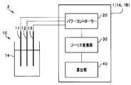
- the electrochemical analysis device 1 includes a power controller 20 that generates a signal to be applied to the electrochemical cell 10, a Fourier transform unit 30, and a calculation unit 40.
- the electrochemical system 2 is a system for analyzing a redox reaction of hexacyanoiron.
- the electrochemical cell 10 includes a working electrode (WE) 11 made of glassy carbon, a counter electrode (CE) 12 made of platinum wire, a reference electrode (RE) 13 made of silver / silver chloride and 3M-NaCl, and an electrolyte 14. And including.
- the electrolyte 14 is an aqueous solution composed of 5 mM K 4 [Fe (CN) 6 ], 5 mM K 3 [Fe (CN) 6 ], and 0.5 M KNO 3 .
- the power controller 20 generates a rectangular wave signal having a voltage of the first frequency f1 based on the reference electrode (RE) 13 and applies it to the working electrode (WE) 11 and the counter electrode (CE) 12 of the electrochemical cell 10. .
- a signal based on current may be used.
- a rectangular wave signal is generated based on the counter electrode (CE) without using the reference electrode (RE) 13 and applied to the working electrode (WE) 11 and the counter electrode (CE) 12 of the electrochemical cell 10.
- the power controller 20 may apply a rectangular wave of current.
- the power controller 20 that outputs a simple rectangular wave signal may have a configuration in which a DC power supply is combined with an ON / OFF switch that operates at a predetermined cycle.
- the Fourier transform unit 30 performs a Fourier transform on the response signal of the electrochemical cell 10 to the rectangular wave signal applied by the power controller 20, and a second frequency (3f1, 5f1, 7f1,...) That is an odd multiple of the first frequency (f1). ) Component for calculating frequency characteristics (input signal and output signal spectrum).
- the calculation unit 40 is an arithmetic circuit that calculates impedance characteristics including impedances and phase differences at a plurality of frequencies of the electrochemical cell 10 based on the input / output spectrum calculated by the Fourier transform unit 30.
- the Fourier transform unit 30 and the calculation unit 40 may be an integrated circuit, for example, a central processing circuit (CPU: Central Processing Unit) that also controls the entire electrochemical system 2.
- the midpoint potential is 0.221 V vs. the potential (immersion potential) between the working electrode (WE) 11 and the reference electrode (RE) 13 when no signal is applied.
- the voltage amplitude is 10 mV.
- 4 and 5 show the response signal of the electrochemical cell 10 to the rectangular wave signal.
- 6 and 7 show the input / output spectrum (power spectrum notation) calculated by the Fourier transform unit 30 from the response signal.
- FIG. 8A is a flowchart for calculating impedance (Z ′, Z ′′) in frequency of the calculation unit 40 when a current rectangular wave is used.
- the generated rectangular wave signal is applied to an electrochemical cell using a power controller.
- the input signal current and the output signal voltage are sampled, and the obtained data is subjected to Fourier transform to obtain the input spectrum I and the output spectrum E.
- the cross-correlation function / The impedance (Z ′, Z ′′) at each frequency is calculated by the autocorrelation function.
- FIG. 8B is a flowchart for calculating the impedance (Z ′, Z ′′) at the frequency of the calculation unit 40 when the voltage rectangular wave is used.
- the generated rectangular wave signal is applied to the electrochemical cell using the power controller.
- the input signal voltage and the output signal current are sampled, and the obtained data is subjected to Fourier transform to obtain an input spectrum E and an output spectrum I. Further, from the cross-correlation function and autocorrelation function of the spectrum, the autocorrelation function /
- the impedance (Z ′, Z ′′) at each frequency is calculated by the cross correlation function.
- FIG. 9 is a Nyquist plot of the electrochemical cell 10.
- the black circles indicate the impedance obtained by the normal AC impedance method.
- the frequency of a sine wave (voltage amplitude: 10 mV) was scanned from 100 kHz to 1 Hz using a frequency characteristic analyzer and a potentiostat.
- the electrochemical system 2 can acquire the impedance characteristics of the electrochemical cell 10 similar to the AC impedance method, while having a simple configuration without a frequency characteristic analyzer and a potentiostat. By analyzing the acquired impedance characteristics using an equivalent circuit model, it is possible to grasp the characteristics and the like of each component such as an electrode and an electrolyte constituting the electrochemical cell 10.
- the intensity of the second frequency multiplied by n in the input / output spectrum calculated by the Fourier transform unit 30 is 1 / n of the intensity of the first frequency. For this reason, it is difficult to acquire a high frequency component in a system with many noise components. For example, in the power spectrum shown in FIG. 7, the frequency component higher than the frequency 23f1 cannot be used for the analysis using the equivalent circuit model because the variation is large and the reliability is low.
- the input / output spectrum calculated by the Fourier transform unit 30 preferably includes a plurality of second frequency (f2) components, and includes three or more second frequency (f2) components. It is particularly preferred.
- the second frequency f2 can be acquired up to 23 times the frequency (23f3) of the first frequency f1. That is, impedances at a total of 12 types of frequencies were obtained.
- the second frequency f2 can be acquired up to 7f1
- the second frequency f2 can be acquired only as 3f1.
- the sampling rate is at least 100 times the first frequency f1.
- noise is likely to occur at the portion where the positive / negative of the current in the power controller 20 is reversed.
- the power controller 20 of the electrochemical analysis device 2 can use a DC power source that is cheaper than the AC power source. Furthermore, the power controller 20 that generates a DC rectangular wave may have a simple configuration in which ON / OFF control is performed only on a signal having a predetermined potential or current value.
- the input / output spectrum calculated by the Fourier transform unit 30 included only a component having a frequency (3f1, etc.) that is an odd multiple of the first frequency (f1).
- frequencies (2f1, 4f1,...) That are integer multiples of the first frequency (f1) are included due to the effect of the response speed of the cell 10. In some cases.
- the input / output spectrum calculated by the Fourier transform unit 30 may include a component having a frequency that is an integral multiple of the first frequency (f1).
- the rectangular wave signal output from the power controller 20 is not limited to a waveform with a very steep rise.
- the rectangular wave signal output from the power controller 20 is also regarded as a so-called sawtooth wave that changes with a certain slope as the frequency is increased.
- the rectangular wave signal output from the power controller 20 is not limited to a waveform having a very steep rise and fall.
- the rectangular wave signal output from the power controller 20 is also regarded as a so-called triangular wave that changes with a certain inclination as the frequency is increased. That is, the rectangular wave in this embodiment is a concept including a sawtooth wave and a triangular wave.
- the rectangular wave signal output from the power controller 20 may be positively converted into a sawtooth signal by using a delay circuit such as an LC circuit.
- the input / output spectrum calculated by the Fourier transform unit 30 includes a frequency component that is an integral multiple of the first frequency (f1).
- the power controller 20 is configured by a rectangular wave signal having the first frequency (f1), which is lower than the first frequency (f1).
- the signal of the frequency (f3) is applied, and the Fourier transform unit calculates an input / output spectrum including the component of the third frequency (f3).
- the Fourier transform unit 30 includes a component of the first frequency (f1) of the rectangular wave signal, a component of an odd multiple of the frequency (3f1, 5f1, 7f1,...) Higher than the first frequency (f1), and the first An input / output spectrum including a component of the third frequency (f3) lower than the frequency (f1) is calculated. Furthermore, an input / output spectrum includes a component having an odd multiple of the third frequency (f3).
- the power controller 20 includes a pseudo sine having a third frequency (f3) lower than the first frequency (f1), which is configured by a rectangular wave signal having the first frequency (f1). Generate a wave signal.
- the electrochemical analysis apparatus 1A (electrochemical system 2A) according to the present modification can detect a frequency component based on the third frequency (f3) in addition to the effect of the electrochemical analysis apparatus 1 (electrochemical system 2). Improves the accuracy of impedance analysis.
- the pseudo sine wave can be regarded as a sine wave. That is, when acquiring low-frequency impedance, the power controller 20 can be used as a sine wave generator.
- noise may occur when switching from a positive voltage to a negative voltage and when switching from a negative voltage to a positive voltage.
- noise may occur when switching from a positive current to a negative current and when switching from a negative current to a positive current.
- the power controller 20 applies rectangular wave signals having a plurality of first frequencies f1A and f1B, and the Fourier transform unit 30 has a plurality of first frequencies.
- An input / output spectrum including a third frequency component that is an odd multiple of each of the frequencies is calculated.
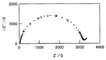
- the Fourier transform unit 30 calculates It is the Nyquist plot of the electrochemical cell 10 which plotted the data acquired from the input-output spectrum by the white circle. Black circles are the same data as shown in FIG. 9 and acquired by the normal AC impedance method.
- f1A 5 Hz
- 3f1A 15 Hz
- 5f1A 25 Hz
- 7f1A 35 Hz
- 9f1A 45 Hz
- f1B 50 Hz
- 3f1B 150 Hz
- 5f1B 250 Hz
- 7f1B 350 Hz
- 9f1B 450 Hz
- f1C 250 Hz
- Impedances Z ′ and Z ′′ at a total of 16 frequencies of 3f1C 750 Hz
- 5f1C 1250 Hz
- 7f1C 1750 Hz
- f1D 500 Hz
- 3f1D 1500 Hz were obtained.
- the electrochemical analysis apparatus 1B (electrochemical system 2B) according to the present modification can acquire highly accurate impedance at more frequencies in addition to the effects of the electrochemical analysis apparatus 1 (electrochemical system 2).
- the frequency of the plurality of rectangular wave signals output from the power controller 20 it is preferable to set the frequency of the plurality of rectangular wave signals output from the power controller 20 so that the odd multiples of the frequency do not become the same. That is, when the frequency of an odd multiple of the frequency of a plurality of rectangular wave signals becomes the same, the impedance analysis may become unstable due to the error of the component acquired at that frequency. Furthermore, by setting the frequencies so as not to be the same, impedances at more frequencies can be acquired.
- the electrochemical analysis device 1C (electrochemical system 2C) of the second embodiment is similar in basic configuration to the electrochemical analysis device 1 (electrochemical system 2) of the first embodiment. .
- description of the component of the same function is abbreviate
- the electrochemical cell 10A is a large-capacity secondary battery (hereinafter referred to as “battery”) 10C, and the power controller 20C is called an inverter by those skilled in the art.
- the battery 10C is, for example, a lithium ion battery including a positive electrode 11C containing lithium cobalt oxide or the like, a negative electrode 12C containing a carbon material or the like, and an electrolyte 14C in which LiPF 6 is dissolved in cyclic and chain carbonates.
- Electrochemical cell 10A may be a power storage unit that can temporarily store electricity.
- the electrochemical system 2C is a large-scale power storage system of the power system 100.
- the power generation unit 50 such as a wind power generation unit or a solar power generation unit
- the load unit 60 such as a factory or home
- the battery 10C of the electrochemical system 2C is used. Is supplied to the load unit 60.
- the generated power amount exceeds the power consumption amount, the battery 10C is charged.
- the motor is the power generation unit 50 and the load unit 60. That is, when electric power is supplied, the motor is driven, and electric power is generated using the rotation of the motor.
- FIG. 14 and 15 are Nyquist plots in which the impedance characteristics of the battery 10C obtained by the electrochemical system 2C are indicated by white circles, and the impedance characteristics obtained by the normal AC impedance method are indicated by black circles. Five types of Nyquist plots are shown when the charging rate (SOC: State Of Charge) is 90% to 10%.
- SOC State Of Charge
- FIG. 14 is a Nyquist plot of the new battery 10
- FIG. 15 is a Nyquist plot after 200 cycles of the charge / discharge test (deteriorated battery).
- offset current 0.5 A, amplitude ⁇ 0.5 A
- offset current 0.5 A, amplitude ⁇ 0.5 A
- the internal resistance of the battery 10C was as extremely low as 10 m ⁇ , it was not easy to measure using a normal AC impedance method.
- the impedance characteristic of the battery 10C obtained by the electrochemical system 2C is in good agreement with the impedance characteristic obtained by the normal AC impedance method. That is, the same effect as that of the electrochemical system 2 of the first embodiment can be obtained in the electrochemical system 2 ⁇ / b> C in which the electrochemical cell is the battery 10. Furthermore, the battery 10C has an extremely low internal resistance of 10 m ⁇ , but it was easy to obtain impedance characteristics in the electrochemical system 2C.
- the diameter of the semicircle (R int ) is larger than that in FIG. 14, indicating that the internal resistance has increased. That is, the calculation unit 40 can further quantitatively detect the deterioration of the battery 10C from the impedance characteristics. Moreover, the calculation part 40 can also detect separately the deterioration degree of the positive electrode 11C, the negative electrode 12C, and an electrolyte by analyzing using an equivalent circuit. Furthermore, the calculation unit 40 can also detect the charging rate of the battery 10C in a state where the deterioration of the battery 10C does not change.
- Electrochemical system 2C can easily obtain impedance characteristics even when the internal resistance of the battery is 10 m ⁇ or less. Furthermore, it is easy to obtain impedance characteristics even for a battery having an internal resistance of 1 m ⁇ or less, which is extremely difficult to measure by a normal AC impedance method.
- the electrochemical system 2C has one battery 10C as an electrochemical cell.
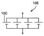
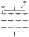
- the electrochemical cell is a battery unit 10D in which a plurality of batteries 10C shown in FIG. 16A are connected in series, a battery unit 10E in which a plurality of batteries 10C shown in FIG. 16B are connected in parallel, or a plurality of batteries 10C shown in FIG.
- the internal resistances of the battery units 10E and 10F in which the batteries are connected in parallel are lower than the internal resistances of the respective batteries 10C.
- the electrochemical system 2C it is easy to obtain impedance characteristics.
- the cell is not limited to a lithium secondary battery as long as it is an electricity storage device that can store electricity, and various secondary batteries and capacitors can also be used.
Landscapes
- Physics & Mathematics (AREA)
- General Physics & Mathematics (AREA)
- Chemical & Material Sciences (AREA)
- Health & Medical Sciences (AREA)
- Life Sciences & Earth Sciences (AREA)
- Electrochemistry (AREA)
- Molecular Biology (AREA)
- Chemical Kinetics & Catalysis (AREA)
- Analytical Chemistry (AREA)
- Biochemistry (AREA)
- General Health & Medical Sciences (AREA)
- Immunology (AREA)
- Pathology (AREA)
- Mathematical Physics (AREA)
- Secondary Cells (AREA)
- Measurement Of Resistance Or Impedance (AREA)
- Charge And Discharge Circuits For Batteries Or The Like (AREA)
Abstract
電気化学解析装置1は、第1の周波数(f1)の矩形波信号を発生し、複数の電極11~13と電解質14とを含む電気化学セル10に印加するパワーコントローラー20と、矩形波信号に対する電気化学セル10の応答信号をフーリエ変換して、第1の周波数f1の整数倍の第2の周波数f2の成分を含む周波数特性を算出するフーリエ変換部30と、フーリエ変換部30が算出する周波数特性をもとに電気化学セル10のインピーダンス特性を算出する算出部40と、を具備する。
Description
本発明の実施形態は、複数の電極と電解質とを含む電気化学セルの特性を測定する電気化学解析装置、および電気化学解析装置を含む電気化学システムに関する。
複数の電極と電解質とを含む電気化学セルのインピーダンス測定は、電気化学反応のメカニズム解明等のために広く使用されている。インピーダンス測定法として、測定対象の電気化学セルに、印加する正弦波信号の周波数を走査する交流インピーダンス法が知られている。
交流インピーダンス法では、周波数特性分析器(FRA:Frequency Response Analyzer)とポテンショスタットとが用いられる。FRAは、電気化学セルに所定の周波数の正弦波信号を印加するための周波数応答信号を出力する。ポテンショスタットは電気化学セルに印加する電圧(電流)をFRAからの周波数信号に基づき制御する。
正弦波信号の周波数を走査することで、複数の周波数におけるインピーダンス、すなわちインピーダンスの周波数特性が取得される。インピーダンスの周波数特性を、Z’(実数インピーダンス)軸を抵抗成分、Z”(虚数インピーダンス)軸をリアクタンス成分(通常は容量性)とする複素平面図に表したインピーダンスの軌跡が、ナイキストプロット(コールコールプロット)である。
図1に示したナイキストプロットは、電解質抵抗Rs、電荷移動抵抗及び被膜抵抗などから成る界面抵抗Rintと、それらに付随する電気二重層などの容量Cと、及び電荷キャリアの拡散Zwと、を考慮した単純なモデルの場合である。すなわち、参照極を用いた電気化学セルでの単純な系の電気化学反応は、電解質中のイオンの移動、電極界面での電荷移動反応、それに伴うイオンの拡散から構成される。なお、参照極を用いない電気化学セルでは、2つの電極(正極、負極)のインピーダンスが含まれるので、半円の軌跡は少なくとも2つの半円が重なった軌跡となる。軌跡を適当な等価回路モデルを用いて解析することで、電気化学セルを構成する複数の電極、及び電解質等の構成要素毎の特性を把握できる。
例えば、界面抵抗Rintを示す半円の径が大きくなった場合には、電気化学セルに変化が生じたことを示している。すなわち、二次電池では電池が劣化したことを示している。電気化学セルがリチウムイオン二次電池の場合では、結晶構造の変化など活物質自身の劣化のためや、電解質中のリチウムイオン電解質成分や有機溶媒が分解し、電解質分解生成物として負極及び正極の表面に有機物や無機物の形で堆積し、リチウムイオンの挿入脱離が阻害されるため、抵抗が上昇すると推察される。
近年、普及が図られている、電気自動車等は、電気化学セルである二次電池を動力源としている。しかし、交流インピーダンス法にて特性を評価するために、それぞれの自動車に周波数特性分析器及びポテンショスタットを搭載することはコスト高となるため現実的ではない。
また、低炭素社会の実現に向けて、太陽光発電または風力発電といった再生可能エネルギーの導入が進められている。再生可能エネルギーを用いて安定した電力供給を行うためには、大規模蓄電システムが不可欠である。
大規模蓄電システムは、大容量の二次電池を主要構成要素としている。大容量の二次電池は内部抵抗が非常に低い。このため、交流インピーダンス法にて評価するためには、非常に高価な大容量のポテンショスタットが必要である。例えば、二次電池の内部抵抗が10mΩの場合、電圧を3Vに制御するにはポテンショスタットの信号電流は300Aが必要となり、内部抵抗が1mΩの場合では信号電流は3000Aが必要である。また、電圧コントロールも容易ではない。
なお、日本国特開2003-090869号公報には、複数の周波数の正弦波を重畳した信号を電池に印加し、応答信号をフーリエ変換することで、複数の周波数におけるインピーダンスを取得する測定装置が開示されている。
また、日本国特開2012-185167号公報には、複数の電池を有する蓄電装置において、一の電池から他の電池に擬似正弦波信号を印加することで、インピーダンスを測定することが開示されている
これに対して、本発明の実施形態は、電気化学セルのインピーダンス特性が取得できる簡単な構成の電気化学解析装置、および前記電気化学解析装置を含む電気化学システムを提供することを目的とする。
これに対して、本発明の実施形態は、電気化学セルのインピーダンス特性が取得できる簡単な構成の電気化学解析装置、および前記電気化学解析装置を含む電気化学システムを提供することを目的とする。
本発明の実施形態の電気化学解析装置は、第1の周波数の矩形波信号を発生し、複数の電極と電解質とを含む電気化学セルに印加するパワーコントローラーと、前記矩形波信号に対する前記電気化学セルの応答信号をフーリエ変換して、前記第1の周波数の整数倍の第2の周波数の成分を含む周波数特性を算出するフーリエ変換部と、前記フーリエ変換部が算出する前記周波数特性をもとに前記電気化学セルのインピーダンス特性を算出する算出部と、を具備する。
本発明の別の実施形態の電気化学システムは、複数の電極と電解質とを含む電気化学セルと、第1の周波数の矩形波信号を発生し、前記電気化学セルに印加するパワーコントローラーと、前記矩形波信号に対する前記電気化学セルの応答信号をフーリエ変換して、前記第1の周波数の整数倍の第2の周波数の成分を含む周波数特性を算出するフーリエ変換部と、前記フーリエ変換部が算出する前記周波数特性をもとに前記電気化学セルのインピーダンス特性を算出する算出部と、を具備する電気化学解析装置とを含む。
<第1実施形態>
図2に示すように、第1実施形態の電気化学システム2は、電気化学セル10と電気化学解析装置1とを含む。電気化学解析装置1は、電気化学セル10に印加する信号を発生するパワーコントローラー20と、フーリエ変換部30と、算出部40と、を具備する。
図2に示すように、第1実施形態の電気化学システム2は、電気化学セル10と電気化学解析装置1とを含む。電気化学解析装置1は、電気化学セル10に印加する信号を発生するパワーコントローラー20と、フーリエ変換部30と、算出部40と、を具備する。
電気化学システム2は、ヘキサシアノ鉄の酸化還元反応を解析するためのシステムである。電気化学セル10は、グラッシーカーボンからなる作用極(WE)11と、白金線からなる対極(CE)12と、銀/塩化銀と3M-NaClとからなる参照極(RE)13と、電解質14と、を含む。電解質14は、5mMのK4[Fe(CN)6]と5mMのK3[Fe(CN)6]と0.5MのKNO3とからなる水溶液である。
パワーコントローラー20は、第1の周波数f1の電圧の矩形波信号を参照極(RE)13を基準に発生し、電気化学セル10の作用極(WE)11と対極(CE)12とに印加する。電圧に替えて電流を基準とする信号を用いてもよい。また、参照極(RE)13を使用せず、対極(CE)を基準に矩形波信号を発生し、電気化学セル10の作用極(WE)11と対極(CE)12とに印加してもよい。パワーコントローラー20は、電流の矩形波を印可しても良い。単純な矩形波信号を出力するパワーコントローラー20は、例えば、直流電源に所定の周期で動作するON/OFFスイッチを組み合わせただけの構成であってもよい。
フーリエ変換部30はパワーコントローラー20が印加した矩形波信号に対する電気化学セル10の応答信号をフーリエ変換し、第1の周波数(f1)の奇数倍の第2の周波数(3f1、5f1、7f1、、)の成分を含む周波数特性(入力信号と出力信号のスペクトル)を算出する演算回路である。算出部40は、フーリエ変換部30が算出した入出力スペクトルをもとに電気化学セル10の複数の周波数におけるインピーダンスと位相差からなるインピーダンス特性を算出する演算回路である。フーリエ変換部30と算出部40とは、一体の回路、例えば、電気化学システム2の全体の制御も行う中央演算回路(CPU:Central Processing Unit)であってもよい。
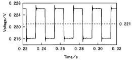
図3は、パワーコントローラー20が出力する第1の周波数(f1=50Hz)の矩形波信号を示している。中点電位は信号を印加しないときの作用極(WE)11と参照極(RE)13との間の電位(浸漬電位)の、0.221V vs.Ag/AgClである。電圧振幅は10mVである。
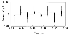
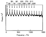
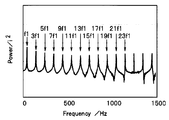
図4及び図5は、矩形波信号に対する電気化学セル10の応答信号を示している。そして、図6及び図7は、フーリエ変換部30が応答信号から算出した入出力スペクトル(パワースペクトル表記)を示している。
図6及び図7に示すように、フーリエ変換部30が算出したパワースペクトルには、第1の周波数(f1=50Hz)のピークに加えて、第1の周波数(f1)の奇数倍の第2の周波数(3f1=150Hz~23f1=1150Hz)のピークが含まれていた。すなわち、第1の周波数(f1)の矩形波信号を印加することで、第1の周波数(f1)よりも高い複数の第2の周波数(f2)の成分が取得される。
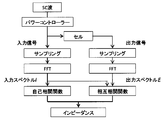
図8Aは、電流矩形波を用いたときの算出部40の、周波数におけるインピーダンス(Z’、Z”)を算出するフローチャートである。作成した矩形波信号をパワーコントローラーを用いて電気化学セルに印可し、入力信号電流及び出力信号電圧をサンプリングし、得られたデータをフーリエ変換により入力スペクトルIと出力スペクトルEを得る。またそのときのスペクトルの相互相関関数及び自己相関関数から、相互相関関数/自己相関関数により、それぞれの周波数におけるインピーダンス(Z’、Z”)を算出する。
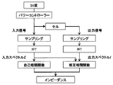
図8Bは、電圧矩形波を用いたときの算出部40の、周波数におけるインピーダンス(Z’、Z”)を算出するフローチャートである。作成した矩形波信号をパワーコントローラーを用いて電気化学セルに印可し、入力信号電圧及び出力信号電流をサンプリングし、得られたデータをフーリエ変換により入力スペクトルEと出力スペクトルIを得る。またそのときのスペクトルの相互相関関数及び自己相関関数から、自己相関関数/相互相関関数により、それぞれの周波数におけるインピーダンス(Z’、Z”)を算出する。
図9は、電気化学セル10のナイキストプロットである。白丸は、フーリエ変換部30が算出した入出力スペクトルの第1の周波数(f1=50Hz)、及び、11種類の第2の周波数f2(3f1=150Hz~23f1=1150Hz)をもとにしたインピーダンスを示しており、黒丸は通常の交流インピーダンス法により取得されたインピーダンスを示している。なお、通常の交流インピーダンス法では、周波数特性分析器及びポテンショスタットを用いて、正弦波(電圧振幅:10mV)の周波数を100kHzから1Hzまで走査した。
図9に示すように、実施形態の電気化学システム2により得られたナイキストプロットと、通常の交流インピーダンス法で得られたナイキストプロットとは非常に良く一致している。
以上の結果から明らかなように、電気化学システム2は、周波数特性分析器及びポテンショスタットを有しない簡単な構成でありながら、交流インピーダンス法と同様の、電気化学セル10のインピーダンス特性が取得できる。取得されたインピーダンス特性を等価回路モデルを用いて解析することで、電気化学セル10を構成する電極及び電解質等の構成要素毎の特性等を把握できる。
なお、フーリエ変換部30が算出する入出力スペクトルにおける、n倍の第2の周波数の強度は、第1の周波数の強度の1/nとなる。このため、ノイズ成分が多い系では高周波成分の取得は困難となる。例えば、図7に示したパワースペクトルでは、周波数23f1よりも高い周波数の成分は、ばらつきが大きく信頼性に欠けるため等価回路モデルを用いた解析に用いることはできなかった。
少なくとも1つの第1の周波数(f1)の3倍の第2の周波数(3f1)の成分が取得されただけ、すなわち、2点のデータからなるナイキストプロットであっても、解析は不可能ではない。フーリエ変換部30が算出する入出力スペクトルには、複数の第2の周波数(f2)の成分が含まれていることが好ましく、3以上の第2の周波数(f2)の成分が含まれていることが特に好ましい。
なお、電気化学システム2においては、第1の周波数(f1)が、5~50Hzでは、第2の周波数f2として、第1の周波数f1の23倍の周波数(23f3)まで取得可能であった。すなわち、合計12種類の周波数におけるインピーダンスが取得できた。これに対して、f1=250Hzでは、第2の周波数f2は7f1まで取得可能であり、f1=500Hzでは第2の周波数f2は3f1しか取得できなかった。
第2の周波数f2をもとにしたインピーダンス応答を安定して得るためには、高いサンプリングレートでの測定が好ましい。サンプリングレートが高いほど、高周波数のf2の測定が容易である。サンプリングレートは第1周波数f1の100倍以上あることがより好ましい。
高い周波数でのf1では、パワーコントローラー20での電流の正負が反転する部分にてノイズが発生しやすい。ノイズが発生した場合には電位または電流値をオフセットして電流の正負が反転しないようにすることが好ましい。
すなわち、電気化学解析装置2のパワーコントローラー20は、交流電源よりも安価な直流電源を用いることができる。さらに、直流矩形波を発生するパワーコントローラー20は、所定の電位または電流値の信号を単にON/OFF制御する簡単な構成でもよい。
パワーコントローラー20での電流値が0付近では、十分な電流値が得られる領域とは異なる電流波形を示すことがある。このような場合には電圧または電流値をオフセットして電流が0にならないようにすることが好ましい。
また、フーリエ変換部30が算出する入出力スペクトルには、第1の周波数(f1)の奇数倍の周波数(3f1等)の成分だけが含まれていた。これに対して、第1の周波数(f1)がより高くなると、セル10の応答速度の影響から、第1の周波数(f1)の整数倍の周波数(2f1、4f1,、)が含まれてくる場合もある。
すなわち、フーリエ変換部30が算出する入出力スペクトルには、第1の周波数(f1)の整数倍の周波数の成分が含まれていてもよい。
パワーコントローラー20が出力する矩形波信号は、立ち上がりが非常に急峻な波形に限られるものではない。パワーコントローラー20が出力する矩形波信号も、周波数を上げていくと、ある傾きで変化する、いわゆる鋸波と見なされる。また、パワーコントローラー20が出力する矩形波信号は、立ち上がり立ち下がりが非常に急峻な波形に限られるものではない。パワーコントローラー20が出力する矩形波信号も、周波数を上げていくと、ある傾きで変化する、いわゆる三角波と見なされる。すなわち、本実施形態における矩形波とは、鋸波や三角波も含む概念である。
更には、パワーコントローラー20が出力する矩形波信号を、LC回路等の遅延回路を用いて、積極的に鋸波信号としてもよい。
鋸波や三角波などでは、フーリエ変換部30が算出する入出力スペクトルには、第1の周波数(f1)の整数倍の周波数の成分が含まれる。
<第1実施形態の変形例1>
本変形例の電気化学解析装置1A(電気化学システム2A)では、パワーコントローラー20が、第1の周波数(f1)の矩形波信号により構成された、第1の周波数(f1)よりも低い第3の周波数(f3)の信号を印加し、フーリエ変換部が、第3の周波数(f3)の成分を含む入出力スペクトルを算出する。
本変形例の電気化学解析装置1A(電気化学システム2A)では、パワーコントローラー20が、第1の周波数(f1)の矩形波信号により構成された、第1の周波数(f1)よりも低い第3の周波数(f3)の信号を印加し、フーリエ変換部が、第3の周波数(f3)の成分を含む入出力スペクトルを算出する。
フーリエ変換部30が矩形波信号の第1の周波数(f1)の成分、第1の周波数(f1)よりも高い奇数倍の周波数(3f1、5f1、7f1、、、)の成分、及び、第1の周波数(f1)よりも低い第3の周波数(f3)の成分を含む入出力スペクトルを算出する。更に第3の周波数(f3)の奇数倍の周波数の成分も入出力スペクトルには含まれている。
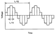
例えば、図10に示すように、パワーコントローラー20は、第1の周波数(f1)の矩形波信号により構成された、第1の周波数(f1)よりも低い第3の周波数(f3)の擬似正弦波信号を生成する。
本変形例の電気化学解析装置1A(電気化学システム2A)は、電気化学解析装置1(電気化学システム2)が有する効果に加えて、第3の周波数(f3)にもとづく周波数成分も検出できるため、よりインピーダンス解析の精度が高くなる。
なお、図11に示すように、例えば、第1の周波数(f1)が、第3の周波数(f3)よりも十分に高い場合には、擬似正弦波は、正弦波と見なすことができる。すなわち、低周波のインピーダンスを取得する場合には、パワーコントローラー20を正弦波発生装置して使用することもできる。
パワーコントローラー20のバイポーラー機能によっては、擬似波形が交流波形の場合に、正電圧から負電圧に切り替えるとき、及び負電圧から正電圧に切り替えるときに、ノイズが発生することがある。また、パワーコントローラー20のバイポーラー機能によっては、擬似波形が交流波形の場合に、正電流から負電流に切り替えるとき、及び負電流から正電流に切り替えるときに、ノイズが発生することがある。ノイズを発生させたくない場合には電圧または電流値をオフセットして電圧または電流の正負が反転しないようにすることが好ましい。
なお、第3の周波数(f3)をより低周波化することにより、ナイキストプロットから電荷キャリアの拡散Zw、すなわち、ワールブルグインピーダンスの解析も可能である。
<第1実施形態の変形例2>
本変形例の電気化学解析装置1B(電気化学システム2B)では、パワーコントローラー20が、複数の第1の周波数f1A、f1B、の矩形波信号を印加し、フーリエ変換部30が、複数の第1の周波数のそれぞれの奇数倍の第3の周波数の成分を含む入出力スペクトルを算出する。
本変形例の電気化学解析装置1B(電気化学システム2B)では、パワーコントローラー20が、複数の第1の周波数f1A、f1B、の矩形波信号を印加し、フーリエ変換部30が、複数の第1の周波数のそれぞれの奇数倍の第3の周波数の成分を含む入出力スペクトルを算出する。
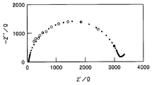
図12には、パワーコントローラー20が、fA1=5Hz、fB1=50Hz、fC1=250Hz、fD1=500Hzの4種類の第1の周波数の矩形波信号を順に出力したときに、フーリエ変換部30が算出した入出力スペクトルから取得されたデータを白丸でプロットした電気化学セル10のナイキストプロットである。黒丸は図9に示したのと同じ、通常の交流インピーダンス法により取得されたデータである。
すなわち、入出力スペクトルから、f1A=5Hz、3f1A=15Hz、5f1A=25Hz、7f1A=35Hz、9f1A=45Hz、f1B=50Hz、3f1B=150Hz、5f1B=250Hz、7f1B=350Hz、9f1B=450Hz、f1C=250Hz、3f1C=750Hz、5f1C=1250Hz、7f1C=1750Hz、f1D=500Hz、3f1D=1500Hzの合計16種類の周波数におけるインピーダンスZ’、Z”が取得された。
本変形例の電気化学解析装置1B(電気化学システム2B)は、電気化学解析装置1(電気化学システム2)が有する効果に加えて、より多くの周波数における精度の高いインピーダンスが取得可能である。
なおパワーコントローラー20が出力する複数の矩形波信号の周波数は、その奇数倍の周波数が同じにならないように設定することが好ましい。すなわち、複数の矩形波信号の周波数の奇数倍の周波数が同じになった場合に、その周波数で取得される成分の誤差からインピーダンス解析が不安定になることがある。更に、周波数が同じにならないように設定することにより、より多くの周波数におけるインピーダンスが取得可能である。
<第2実施形態>
図13に示すように、第2実施形態の電気化学解析装置1C(電気化学システム2C)は、第1実施形態の電気化学解析装置1(電気化学システム2)と、基本構成は類似している。このため、同じ機能の構成要素の説明は省略する。
図13に示すように、第2実施形態の電気化学解析装置1C(電気化学システム2C)は、第1実施形態の電気化学解析装置1(電気化学システム2)と、基本構成は類似している。このため、同じ機能の構成要素の説明は省略する。
電気化学システム2Cでは、電気化学セル10Aが大容量二次電池(以下、「電池」という)10Cであり、パワーコントローラー20Cは、当業者にはインバーターと呼ばれている。電池10Cは、例えば、リチウムコバルト酸化物等を含有する正極11Cと、炭素材料等を含有する負極12Cと、LiPF6を環状及び鎖状カーボネートに溶解した電解質14Cと、を含むリチウムイオン電池である。なお、電気化学セル10Aは、電気を一時的に蓄えることのできる蓄電部であってもよい。
そして、電気化学システム2Cは、電力システム100の大規模蓄電システムである。電力システム100では、風力発電部、太陽光発電部等の発電部50からの発電電力量が、工場、家庭等の負荷部60の電力消費量では不足したときに、電気化学システム2Cの電池10Cから負荷部60に電力が供給される。これに対して、発電電力量が電力消費量を上回ったときには、電池10Cが充電される。
なお、電気化学システム2Cが電気自動車の蓄電システムの場合には、モーターが発電部50及び負荷部60となる。すなわち、電力が供給されるとモーターは駆動され、モーターの回転を利用して発電も行われる。
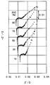
図14及び図15は、電気化学システム2Cにより取得された電池10Cのインピーダンス特性を白丸で、通常の交流インピーダンス法で取得されたインピーダンス特性を黒丸で表示しているナイキストプロットであり、電池10Cの充電率(SOC:State Of Charge)が90%~10%の場合の5種類のナイキストプロットを示している。そして、図14は、新品の電池10のナイキストプロットであり、図15は充放電試験を200サイクル行った後(劣化電池)のナイキストプロットである。
なお、電気化学システム2Cでは、パワーコントローラー20Cが、50Hzの矩形波信号(オフセット電流=0.5A、振幅±0.5A)の信号を、電池10に印加した。通常の交流インピーダンス法では、周波数特性分析器及び大容量ポテンショスタットを用いて、正弦波(オフセット電流=0.5A、振幅±0.5A)の周波数を100kHzから1Hzまで走査した。ただし、電池10Cは、内部抵抗が10mΩと極めて低いため、通常の交流インピーダンス法での測定は容易ではなかった。
図14及び図15から、電気化学システム2Cにより取得された電池10Cのインピーダンス特性は、通常の交流インピーダンス法で取得されたインピーダンス特性と良く一致している。すなわち、電気化学セルが電池10の電気化学システム2Cにも、第1実施形態の電気化学システム2と同様の効果が得られる。更に、電池10Cは、内部抵抗が10mΩと極めて低いが、電気化学システム2Cではインピーダンス特性の取得は容易であった。
そして、図15では半円の径(Rint)が図14よりも増加しており、内部抵抗が増加したことを示している。すなわち、算出部40はインピーダンス特性から更に電池10Cの劣化を定量的に検出できる。また、算出部40は、等価回路を用いて解析することで、正極11C、負極12C、及び電解質の劣化度を分離して検出することもできる。更に、算出部40は、電池10Cの劣化が変化しない状態では、電池10Cの充電率を検出することもできる。
電気化学システム2Cは、電池の内部抵抗が10mΩ以下であってもインピーダンス特性の取得が容易である。更に、通常の交流インピーダンス法では測定を行うことが極めて困難な内部抵抗が1mΩ以下の電池であってもインピーダンス特性の取得が容易である。
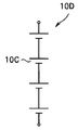
また、説明を簡単にするため、電気化学システム2Cは電気化学セルとして、1個の電池10Cを有していた。しかし、電気化学セルが、図16Aに示す複数の電池10Cが直列接続された電池ユニット10D、図16Bに示す複数の電池10Cが並列接続された電池ユニット10E、又は図16Cに示す複数の電池10Cが直列及び並列に接続された電池ユニット10Fであっても、電気化学セルに信号を印加することで、複数の電池10Cからなる電池ユニット10Eの全体としての特性変化を検出することもできる。
特に、電池を並列接続した電池ユニット10E、10Fの内部抵抗は、それぞれの電池10Cの内部抵抗よりも低くなるが、電気化学システム2Cによれば、インピーダンス特性の取得が容易である
更に、電気化学セルとしては、電気を蓄電できる蓄電デバイスであれば、リチウム二次電池に限られるものではなく、様々な二次電池やキャパシタを用いることもできる。
更に、電気化学セルとしては、電気を蓄電できる蓄電デバイスであれば、リチウム二次電池に限られるものではなく、様々な二次電池やキャパシタを用いることもできる。
本発明は、上述した実施形態等に限定されるものではなく、本発明の要旨を変えない範囲において、種々の変更、改変、例えば、実施形態の構成要素の組み合わせ等が可能である。
本出願は、2012年12月27日に日本国に出願された特願2012-285550号を優先権主張の基礎として出願するものであり、上記の開示内容は、本願明細書、請求の範囲、図面に引用されたものとする。
Claims (12)
- 第1の周波数の矩形波信号を発生し、複数の電極と電解質とを含む電気化学セルに印加するパワーコントローラーと、
前記矩形波信号に対する前記電気化学セルの応答信号をフーリエ変換して、前記第1の周波数の整数倍の第2の周波数の成分を含む周波数特性を算出するフーリエ変換部と、
前記フーリエ変換部が算出する前記周波数特性をもとに前記電気化学セルのインピーダンス特性を算出する算出部と、を具備することを特徴とする電気化学解析装置。 - 前記第2の周波数が、前記第1の周波数の奇数倍の周波数であることを特徴とする請求項1に記載の電気化学解析装置。
- 前記パワーコントローラーが、複数の前記第1の周波数の矩形波信号により構成された、前記第1の周波数よりも低い第3の周波数の信号を前記電気化学セルに印加し、
前記フーリエ変換部が、前記第3の周波数の成分を含む周波数特性を算出することを特徴とする請求項2に記載の電気化学解析装置。 - 前記パワーコントローラーが、複数の周波数の矩形波信号を前記電気化学セルに印加し、
前記フーリエ変換部が、前記複数の周波数のそれぞれの整数倍の周波数の成分を含む周波数特性を算出することを特徴とする請求項2に記載の電気化学解析装置。 - 前記複数の矩形波信号の周波数が、その奇数倍の周波数が異なるように設定されていることを特徴とする請求項4に記載の電気化学解析装置。
- 前記電気化学セルが蓄電デバイスであることを特徴とする請求項1から請求項5のいずれか1項に記載の電気化学解析装置。
- 前記算出部が、前記インピーダンス特性から更に前記蓄電デバイスの特性変化を検出することを特徴とする請求項6に記載の電気化学解析装置。
- 前記パワーコントローラーが、互いに接続された複数の蓄電デバイスからなる蓄電ユニットに対して前記矩形波信号を印加し、前記算出部が、前記蓄電ユニットの特性変化を検出することを特徴とする請求項7に記載の電気化学解析装置。
- 前記蓄電デバイスが、二次電池であることを特徴とする請求項7、又は請求項8に記載の電気化学解析装置。
- 前記二次電池の内部抵抗が10mΩ以下であることを特徴とする請求項9に記載の電気化学解析装置。
- 前記パワーコントローラーが発生する前記矩形波信号が直流であることを特徴とする請求項1から請求項10のいずれか1項に記載の電気化学解析装置。
- 請求項1から請求項11のいずれか1項に記載の電気化学解析装置と、
前記電気化学セルと、を含むことを特徴とする電気化学システム。
Priority Applications (1)
| Application Number | Priority Date | Filing Date | Title |
|---|---|---|---|
| US14/758,052 US9977059B2 (en) | 2012-12-27 | 2013-12-26 | Electrochemical analysis apparatus and electrochemical system |
Applications Claiming Priority (2)
| Application Number | Priority Date | Filing Date | Title |
|---|---|---|---|
| JP2012285550A JP6226261B2 (ja) | 2012-12-27 | 2012-12-27 | 電気化学システム |
| JP2012-285550 | 2012-12-27 |
Publications (1)
| Publication Number | Publication Date |
|---|---|
| WO2014104188A1 true WO2014104188A1 (ja) | 2014-07-03 |
Family
ID=51021262
Family Applications (1)
| Application Number | Title | Priority Date | Filing Date |
|---|---|---|---|
| PCT/JP2013/084877 Ceased WO2014104188A1 (ja) | 2012-12-27 | 2013-12-26 | 電気化学解析装置および電気化学システム |
Country Status (3)
| Country | Link |
|---|---|
| US (1) | US9977059B2 (ja) |
| JP (1) | JP6226261B2 (ja) |
| WO (1) | WO2014104188A1 (ja) |
Cited By (4)
| Publication number | Priority date | Publication date | Assignee | Title |
|---|---|---|---|---|
| WO2022249709A1 (ja) * | 2021-05-24 | 2022-12-01 | 日置電機株式会社 | インピーダンス測定装置 |
| WO2022249708A1 (ja) * | 2021-05-24 | 2022-12-01 | 日置電機株式会社 | 信号注入装置およびインピーダンス測定装置 |
| JP2022180295A (ja) * | 2021-05-24 | 2022-12-06 | 日置電機株式会社 | 信号注入装置およびインピーダンス測定装置 |
| JP2022180277A (ja) * | 2021-05-24 | 2022-12-06 | 日置電機株式会社 | インピーダンス測定装置 |
Families Citing this family (29)
| Publication number | Priority date | Publication date | Assignee | Title |
|---|---|---|---|---|
| US12075957B2 (en) * | 2014-03-24 | 2024-09-03 | Intelligent Cleaning Equipment Holdings Co. Ltd. | Floor cleaning machines having intelligent systems, associated sub-assemblies incorporating intelligent systems, and associated methods of use |
| CN112220406A (zh) * | 2014-03-24 | 2021-01-15 | 智能清洁设备控股有限公司 | 具有智能系统的地板清洁机器 |
| JP6508729B2 (ja) | 2016-12-02 | 2019-05-08 | トヨタ自動車株式会社 | 電池状態推定装置 |
| JP6614176B2 (ja) | 2017-02-09 | 2019-12-04 | トヨタ自動車株式会社 | 電池状態推定装置 |
| JP6575548B2 (ja) | 2017-03-22 | 2019-09-18 | トヨタ自動車株式会社 | 電池状態推定装置 |
| US11051670B2 (en) | 2017-04-13 | 2021-07-06 | Intelligent Cleaning Equipment Holdings Co. Ltd. | Floor cleaning machines having intelligent systems, associated sub-assemblies incorporating intelligent systems, and associated methods of use |
| JP6881156B2 (ja) | 2017-08-24 | 2021-06-02 | トヨタ自動車株式会社 | インピーダンス推定装置 |
| JP6806002B2 (ja) | 2017-08-24 | 2020-12-23 | トヨタ自動車株式会社 | 温度推定装置 |
| DE102017128566A1 (de) * | 2017-12-01 | 2019-06-06 | Endress+Hauser Flowtec Ag | Sensoranordnung zur Anordnung an einer Prozessanlage, sowie Verfahren zum Betrieb der Sensoranordnung und Prozessanlage |
| JP7157909B2 (ja) | 2018-12-20 | 2022-10-21 | トヨタ自動車株式会社 | 電池容量の推定方法、および電池容量の推定装置 |
| JP7157908B2 (ja) * | 2018-12-20 | 2022-10-21 | トヨタ自動車株式会社 | 電池容量の推定方法および電池容量の推定装置 |
| JP7172838B2 (ja) | 2019-04-26 | 2022-11-16 | 株式会社デンソー | 電池監視装置 |
| JP7226147B2 (ja) | 2019-07-04 | 2023-02-21 | 株式会社デンソー | 電池監視装置 |
| JP7522542B2 (ja) | 2019-07-17 | 2024-07-25 | 株式会社デンソー | 電池監視装置 |
| JP7259614B2 (ja) | 2019-07-19 | 2023-04-18 | 株式会社デンソー | 電池監視装置 |
| JP7205410B2 (ja) | 2019-07-26 | 2023-01-17 | 株式会社デンソー | 電池監視装置 |
| JP7167898B2 (ja) * | 2019-10-30 | 2022-11-09 | 株式会社デンソー | 電池監視装置 |
| JP2021078295A (ja) * | 2019-11-12 | 2021-05-20 | 株式会社東芝 | 充電装置、電池診断システム、及び、充電方法 |
| DE112021000699T5 (de) | 2020-01-24 | 2022-11-24 | Denso Corporation | Batteriemessvorrichtung |
| JP2022007515A (ja) * | 2020-06-26 | 2022-01-13 | 株式会社デンソー | 電池診断システム |
| KR102496569B1 (ko) * | 2021-04-13 | 2023-02-06 | 포항공과대학교 산학협력단 | 임피던스 특성을 결정하는 방법 및 디바이스 |
| JP7517256B2 (ja) | 2021-06-10 | 2024-07-17 | 株式会社デンソー | 電池測定装置及び電池状態測定方法 |
| WO2023163137A1 (ja) | 2022-02-27 | 2023-08-31 | 株式会社電知 | インピーダンス測定装置、測定方法および二次電池診断システム |
| JPWO2024111364A1 (ja) | 2022-11-24 | 2024-05-30 | ||
| JPWO2024166301A1 (ja) | 2023-02-09 | 2024-08-15 | ||
| WO2024185073A1 (ja) | 2023-03-08 | 2024-09-12 | 株式会社 東芝 | 電気化学セルに関連する処理方法、処理装置及び処理プログラム |
| WO2024189905A1 (ja) | 2023-03-16 | 2024-09-19 | 株式会社 東芝 | 蓄電池の診断装置、診断システム及び診断方法 |
| DE102024201193A1 (de) * | 2024-02-09 | 2025-08-14 | Schaeffler Technologies AG & Co. KG | Vereinfachtes Verfahren zur Impedanzanalyse elektrischer Bauteile |
| JP2026045765A (ja) | 2024-08-30 | 2026-03-13 | 株式会社東芝 | 電解ユニットの診断方法、電解装置の診断方法、電解ユニットの診断装置、運用システム、及び、電解ユニットの診断プログラム |
Citations (5)
| Publication number | Priority date | Publication date | Assignee | Title |
|---|---|---|---|---|
| JPH01167679A (ja) * | 1987-12-23 | 1989-07-03 | Advantest Corp | インピーダンス測定装置 |
| JP2002330752A (ja) * | 2001-05-08 | 2002-11-19 | Sanden Corp | 微生物数測定装置 |
| JP2003090869A (ja) * | 2001-07-09 | 2003-03-28 | Yokogawa Electric Corp | インピーダンスの測定装置 |
| JP2005180927A (ja) * | 2003-12-16 | 2005-07-07 | Horiba Ltd | インピーダンス測定装置 |
| JP2012015932A (ja) * | 2010-07-05 | 2012-01-19 | Tamagawa Seiki Co Ltd | 正弦波発生回路 |
Family Cites Families (5)
| Publication number | Priority date | Publication date | Assignee | Title |
|---|---|---|---|---|
| US4947130A (en) | 1987-12-23 | 1990-08-07 | Advantest Corporation | Impedance measuring apparatus |
| JPH08125441A (ja) * | 1994-10-20 | 1996-05-17 | Fujitsu Ltd | 波形発生装置 |
| JP3367320B2 (ja) * | 1996-02-26 | 2003-01-14 | 新神戸電機株式会社 | 密閉型鉛蓄電池の劣化判定方法及び装置 |
| JP5367604B2 (ja) * | 2003-08-22 | 2013-12-11 | 古河電気工業株式会社 | 二次電池の内部インピーダンスを測定する方法及び装置 |
| JP4999353B2 (ja) | 2006-04-26 | 2012-08-15 | パナソニック株式会社 | 蓄電装置、携帯機器及び電動車両 |
-
2012
- 2012-12-27 JP JP2012285550A patent/JP6226261B2/ja active Active
-
2013
- 2013-12-26 WO PCT/JP2013/084877 patent/WO2014104188A1/ja not_active Ceased
- 2013-12-26 US US14/758,052 patent/US9977059B2/en active Active
Patent Citations (5)
| Publication number | Priority date | Publication date | Assignee | Title |
|---|---|---|---|---|
| JPH01167679A (ja) * | 1987-12-23 | 1989-07-03 | Advantest Corp | インピーダンス測定装置 |
| JP2002330752A (ja) * | 2001-05-08 | 2002-11-19 | Sanden Corp | 微生物数測定装置 |
| JP2003090869A (ja) * | 2001-07-09 | 2003-03-28 | Yokogawa Electric Corp | インピーダンスの測定装置 |
| JP2005180927A (ja) * | 2003-12-16 | 2005-07-07 | Horiba Ltd | インピーダンス測定装置 |
| JP2012015932A (ja) * | 2010-07-05 | 2012-01-19 | Tamagawa Seiki Co Ltd | 正弦波発生回路 |
Cited By (7)
| Publication number | Priority date | Publication date | Assignee | Title |
|---|---|---|---|---|
| WO2022249709A1 (ja) * | 2021-05-24 | 2022-12-01 | 日置電機株式会社 | インピーダンス測定装置 |
| WO2022249708A1 (ja) * | 2021-05-24 | 2022-12-01 | 日置電機株式会社 | 信号注入装置およびインピーダンス測定装置 |
| JP2022180295A (ja) * | 2021-05-24 | 2022-12-06 | 日置電機株式会社 | 信号注入装置およびインピーダンス測定装置 |
| JP2022180277A (ja) * | 2021-05-24 | 2022-12-06 | 日置電機株式会社 | インピーダンス測定装置 |
| JP7698556B2 (ja) | 2021-05-24 | 2025-06-25 | 日置電機株式会社 | インピーダンス測定装置 |
| JP7794667B2 (ja) | 2021-05-24 | 2026-01-06 | 日置電機株式会社 | 信号注入装置およびインピーダンス測定装置 |
| US12535531B2 (en) | 2021-05-24 | 2026-01-27 | Hioki E.E. Corporation | Impedance measurement device |
Also Published As
| Publication number | Publication date |
|---|---|
| JP2014126532A (ja) | 2014-07-07 |
| US20160195577A1 (en) | 2016-07-07 |
| JP6226261B2 (ja) | 2017-11-08 |
| US9977059B2 (en) | 2018-05-22 |
Similar Documents
| Publication | Publication Date | Title |
|---|---|---|
| JP6226261B2 (ja) | 電気化学システム | |
| JP6370581B2 (ja) | 電気化学解析装置および電気化学システム | |
| Luo et al. | Rapid prediction of the state of health of retired power batteries based on electrochemical impedance spectroscopy | |
| Wang et al. | Fast calculation of broadband battery impedance spectra based on S transform of step disturbance and response | |
| Monem et al. | Lithium-ion batteries: Evaluation study of different charging methodologies based on aging process | |
| CN100495060C (zh) | 用于测量电池容量的方法 | |
| Zhao et al. | A measurement method for determination of dc internal resistance of batteries and supercapacitors | |
| JP3162030B2 (ja) | パルス電流の電圧応答信号を用いた電池容量測定方法及び電池容量測定装置 | |
| CN106970266A (zh) | 一种锂离子电池的eis快速测量方法 | |
| Yokoshima et al. | Application of electrochemical impedance spectroscopy to ferri/ferrocyanide redox couple and lithium ion battery systems using a square wave as signal input | |
| Yokoshima et al. | Impedance measurements of kilowatt-class lithium ion battery modules/cubicles in energy storage systems by square-current electrochemical impedance spectroscopy | |
| CN108663631A (zh) | 一种锂离子电池组电化学阻抗谱在线测量装置 | |
| CN115575714A (zh) | 一种锂电池原位在线快速eis检测方法及装置 | |
| Bohlen | Impedance-based battery monitoring | |
| Watanabe et al. | Determination of electrochemical impedance of lithium-ion battery from charge curve by wavelet transformation | |
| Al Nazer et al. | Classical EIS and square pattern signals comparison based on a well-known reference impedance | |
| Huang et al. | Online impedance measurement of operational batteries utilizing Sinc function signal injection via DC-DC power converter | |
| Yan et al. | Battery impedance measurement using pseudo random binary sequences | |
| Klink et al. | Review–Electrochemical Impedance Spectroscopy for Lithium-Ion Batteries: Measurement and Analysis (for automotive applications) | |
| Luo et al. | AC impedance technique for dynamic and static state of charge analysis for Li-ion battery | |
| CN202330560U (zh) | 单片机产生spwm信号激励的蓄电池阻抗检测装置 | |
| Thanapalan et al. | Advanced EIS techniques for performance evaluation of Li-ion cells | |
| Bechara et al. | Embedded spectroscopy: Potentialities and constraints for onboard battery diagnostics | |
| JP2020047487A (ja) | 電気化学システム、および、電気化学システムの作動方法 | |
| CN119395119A (zh) | 一种筛选高倍率性能电极的方法及其应用 |
Legal Events
| Date | Code | Title | Description |
|---|---|---|---|
| 121 | Ep: the epo has been informed by wipo that ep was designated in this application |
Ref document number: 13868212 Country of ref document: EP Kind code of ref document: A1 |
|
| WWE | Wipo information: entry into national phase |
Ref document number: 14758052 Country of ref document: US |
|
| NENP | Non-entry into the national phase |
Ref country code: DE |
|
| 122 | Ep: pct application non-entry in european phase |
Ref document number: 13868212 Country of ref document: EP Kind code of ref document: A1 |