WO2014104147A1 - 波長変換部材及び発光装置 - Google Patents
波長変換部材及び発光装置 Download PDFInfo
- Publication number
- WO2014104147A1 WO2014104147A1 PCT/JP2013/084777 JP2013084777W WO2014104147A1 WO 2014104147 A1 WO2014104147 A1 WO 2014104147A1 JP 2013084777 W JP2013084777 W JP 2013084777W WO 2014104147 A1 WO2014104147 A1 WO 2014104147A1
- Authority
- WO
- WIPO (PCT)
- Prior art keywords
- wavelength conversion
- light
- conversion member
- phosphor
- resin
- Prior art date
Links
- 238000006243 chemical reaction Methods 0.000 title claims abstract description 140
- 229920005989 resin Polymers 0.000 claims abstract description 29
- 239000011347 resin Substances 0.000 claims abstract description 29
- 229920005992 thermoplastic resin Polymers 0.000 claims abstract description 24
- 239000002245 particle Substances 0.000 claims abstract description 23
- 239000004793 Polystyrene Substances 0.000 claims abstract description 13
- 229920002223 polystyrene Polymers 0.000 claims abstract description 13
- 229920001577 copolymer Polymers 0.000 claims abstract description 12
- PPBRXRYQALVLMV-UHFFFAOYSA-N Styrene Natural products C=CC1=CC=CC=C1 PPBRXRYQALVLMV-UHFFFAOYSA-N 0.000 claims abstract description 11
- 238000009826 distribution Methods 0.000 claims abstract description 7
- 229920000178 Acrylic resin Polymers 0.000 claims abstract description 6
- 239000004925 Acrylic resin Substances 0.000 claims abstract description 6
- 239000004721 Polyphenylene oxide Substances 0.000 claims abstract description 6
- BZHJMEDXRYGGRV-UHFFFAOYSA-N Vinyl chloride Chemical compound ClC=C BZHJMEDXRYGGRV-UHFFFAOYSA-N 0.000 claims abstract description 6
- 229920001778 nylon Polymers 0.000 claims abstract description 6
- 229920005668 polycarbonate resin Polymers 0.000 claims abstract description 6
- 239000004431 polycarbonate resin Substances 0.000 claims abstract description 6
- 229920001225 polyester resin Polymers 0.000 claims abstract description 6
- 239000004645 polyester resin Substances 0.000 claims abstract description 6
- 229920000570 polyether Polymers 0.000 claims abstract description 6
- 229920000098 polyolefin Polymers 0.000 claims abstract description 6
- KRHYYFGTRYWZRS-UHFFFAOYSA-M Fluoride anion Chemical compound [F-] KRHYYFGTRYWZRS-UHFFFAOYSA-M 0.000 claims abstract description 5
- 229910052783 alkali metal Inorganic materials 0.000 claims abstract description 5
- 150000001340 alkali metals Chemical class 0.000 claims abstract description 5
- 229910052792 caesium Inorganic materials 0.000 claims abstract description 5
- 229910052732 germanium Inorganic materials 0.000 claims abstract description 5
- 229910052735 hafnium Inorganic materials 0.000 claims abstract description 5
- 229910052744 lithium Inorganic materials 0.000 claims abstract description 5
- 229910052700 potassium Inorganic materials 0.000 claims abstract description 5
- 229910052701 rubidium Inorganic materials 0.000 claims abstract description 5
- 229910052710 silicon Inorganic materials 0.000 claims abstract description 5
- 229910052708 sodium Inorganic materials 0.000 claims abstract description 5
- 229910052718 tin Inorganic materials 0.000 claims abstract description 5
- 229910052719 titanium Inorganic materials 0.000 claims abstract description 5
- 229910052726 zirconium Inorganic materials 0.000 claims abstract description 5
- 230000001186 cumulative effect Effects 0.000 claims abstract description 4
- OAICVXFJPJFONN-UHFFFAOYSA-N Phosphorus Chemical compound [P] OAICVXFJPJFONN-UHFFFAOYSA-N 0.000 claims description 81
- 239000011572 manganese Substances 0.000 claims description 42
- -1 manganese-activated potassium hexafluorosilicate Chemical class 0.000 claims description 24
- 229910052748 manganese Inorganic materials 0.000 claims description 23
- 239000004743 Polypropylene Substances 0.000 claims description 19
- 229920001155 polypropylene Polymers 0.000 claims description 19
- 230000003287 optical effect Effects 0.000 claims description 13
- 238000000465 moulding Methods 0.000 claims description 11
- XPIIDKFHGDPTIY-UHFFFAOYSA-N F.F.F.P Chemical compound F.F.F.P XPIIDKFHGDPTIY-UHFFFAOYSA-N 0.000 claims description 10
- 239000004677 Nylon Substances 0.000 claims description 5
- PXGOKWXKJXAPGV-UHFFFAOYSA-N Fluorine Chemical compound FF PXGOKWXKJXAPGV-UHFFFAOYSA-N 0.000 claims description 2
- 229910052731 fluorine Inorganic materials 0.000 claims description 2
- 239000011737 fluorine Substances 0.000 claims description 2
- QHIWVLPBUQWDMQ-UHFFFAOYSA-N butyl prop-2-enoate;methyl 2-methylprop-2-enoate;prop-2-enoic acid Chemical compound OC(=O)C=C.COC(=O)C(C)=C.CCCCOC(=O)C=C QHIWVLPBUQWDMQ-UHFFFAOYSA-N 0.000 abstract 1
- NBVXSUQYWXRMNV-UHFFFAOYSA-N fluoromethane Chemical compound FC NBVXSUQYWXRMNV-UHFFFAOYSA-N 0.000 abstract 1
- 238000009877 rendering Methods 0.000 description 22
- PWHULOQIROXLJO-UHFFFAOYSA-N Manganese Chemical compound [Mn] PWHULOQIROXLJO-UHFFFAOYSA-N 0.000 description 19
- 230000005284 excitation Effects 0.000 description 13
- 239000008188 pellet Substances 0.000 description 12
- 230000000052 comparative effect Effects 0.000 description 11
- 238000000034 method Methods 0.000 description 9
- 238000002156 mixing Methods 0.000 description 7
- 239000000843 powder Substances 0.000 description 7
- 238000002834 transmittance Methods 0.000 description 7
- 230000000694 effects Effects 0.000 description 6
- LDXJRKWFNNFDSA-UHFFFAOYSA-N 2-(2,4,6,7-tetrahydrotriazolo[4,5-c]pyridin-5-yl)-1-[4-[2-[[3-(trifluoromethoxy)phenyl]methylamino]pyrimidin-5-yl]piperazin-1-yl]ethanone Chemical compound C1CN(CC2=NNN=C21)CC(=O)N3CCN(CC3)C4=CN=C(N=C4)NCC5=CC(=CC=C5)OC(F)(F)F LDXJRKWFNNFDSA-UHFFFAOYSA-N 0.000 description 5
- 239000003795 chemical substances by application Substances 0.000 description 5
- 238000000295 emission spectrum Methods 0.000 description 5
- 238000005286 illumination Methods 0.000 description 5
- 238000004898 kneading Methods 0.000 description 5
- 229910052688 Gadolinium Inorganic materials 0.000 description 4
- 238000001746 injection moulding Methods 0.000 description 4
- 239000000463 material Substances 0.000 description 4
- 229910052727 yttrium Inorganic materials 0.000 description 4
- 238000011156 evaluation Methods 0.000 description 3
- 239000002994 raw material Substances 0.000 description 3
- 239000000126 substance Substances 0.000 description 3
- KAKZBPTYRLMSJV-UHFFFAOYSA-N Butadiene Chemical compound C=CC=C KAKZBPTYRLMSJV-UHFFFAOYSA-N 0.000 description 2
- 0 CCC(C)CCCC1*CCC1 Chemical compound CCC(C)CCCC1*CCC1 0.000 description 2
- KRHYYFGTRYWZRS-UHFFFAOYSA-N Fluorane Chemical compound F KRHYYFGTRYWZRS-UHFFFAOYSA-N 0.000 description 2
- 229910003564 SiAlON Inorganic materials 0.000 description 2
- 229910004283 SiO 4 Inorganic materials 0.000 description 2
- VYPSYNLAJGMNEJ-UHFFFAOYSA-N Silicium dioxide Chemical compound O=[Si]=O VYPSYNLAJGMNEJ-UHFFFAOYSA-N 0.000 description 2
- 229910052782 aluminium Inorganic materials 0.000 description 2
- 230000015572 biosynthetic process Effects 0.000 description 2
- 229910052791 calcium Inorganic materials 0.000 description 2
- 239000011575 calcium Substances 0.000 description 2
- 229910052733 gallium Inorganic materials 0.000 description 2
- 239000011521 glass Substances 0.000 description 2
- 239000000203 mixture Substances 0.000 description 2
- TWNQGVIAIRXVLR-UHFFFAOYSA-N oxo(oxoalumanyloxy)alumane Chemical compound O=[Al]O[Al]=O TWNQGVIAIRXVLR-UHFFFAOYSA-N 0.000 description 2
- 229920005604 random copolymer Polymers 0.000 description 2
- 238000007789 sealing Methods 0.000 description 2
- 229910052814 silicon oxide Inorganic materials 0.000 description 2
- 230000003595 spectral effect Effects 0.000 description 2
- 238000003786 synthesis reaction Methods 0.000 description 2
- NJHVXCSESBEOEB-UHFFFAOYSA-N (2,6-ditert-butyl-4-methylphenyl) dihydrogen phosphite Chemical compound CC1=CC(C(C)(C)C)=C(OP(O)O)C(C(C)(C)C)=C1 NJHVXCSESBEOEB-UHFFFAOYSA-N 0.000 description 1
- VZSRBBMJRBPUNF-UHFFFAOYSA-N 2-(2,3-dihydro-1H-inden-2-ylamino)-N-[3-oxo-3-(2,4,6,7-tetrahydrotriazolo[4,5-c]pyridin-5-yl)propyl]pyrimidine-5-carboxamide Chemical compound C1C(CC2=CC=CC=C12)NC1=NC=C(C=N1)C(=O)NCCC(N1CC2=C(CC1)NN=N2)=O VZSRBBMJRBPUNF-UHFFFAOYSA-N 0.000 description 1
- NLHHRLWOUZZQLW-UHFFFAOYSA-N Acrylonitrile Chemical compound C=CC#N NLHHRLWOUZZQLW-UHFFFAOYSA-N 0.000 description 1
- 229910052684 Cerium Inorganic materials 0.000 description 1
- VGGSQFUCUMXWEO-UHFFFAOYSA-N Ethene Chemical compound C=C VGGSQFUCUMXWEO-UHFFFAOYSA-N 0.000 description 1
- 239000005977 Ethylene Substances 0.000 description 1
- VAYOSLLFUXYJDT-RDTXWAMCSA-N Lysergic acid diethylamide Chemical compound C1=CC(C=2[C@H](N(C)C[C@@H](C=2)C(=O)N(CC)CC)C2)=C3C2=CNC3=C1 VAYOSLLFUXYJDT-RDTXWAMCSA-N 0.000 description 1
- 239000004698 Polyethylene Substances 0.000 description 1
- OFOBLEOULBTSOW-UHFFFAOYSA-N Propanedioic acid Natural products OC(=O)CC(O)=O OFOBLEOULBTSOW-UHFFFAOYSA-N 0.000 description 1
- XBDQKXXYIPTUBI-UHFFFAOYSA-M Propionate Chemical compound CCC([O-])=O XBDQKXXYIPTUBI-UHFFFAOYSA-M 0.000 description 1
- YKTSYUJCYHOUJP-UHFFFAOYSA-N [O--].[Al+3].[Al+3].[O-][Si]([O-])([O-])[O-] Chemical compound [O--].[Al+3].[Al+3].[O-][Si]([O-])([O-])[O-] YKTSYUJCYHOUJP-UHFFFAOYSA-N 0.000 description 1
- 238000010521 absorption reaction Methods 0.000 description 1
- 239000012190 activator Substances 0.000 description 1
- 238000007792 addition Methods 0.000 description 1
- 239000003513 alkali Substances 0.000 description 1
- 239000003963 antioxidant agent Substances 0.000 description 1
- 230000003078 antioxidant effect Effects 0.000 description 1
- 239000012752 auxiliary agent Substances 0.000 description 1
- 230000005540 biological transmission Effects 0.000 description 1
- XITRBUPOXXBIJN-UHFFFAOYSA-N bis(2,2,6,6-tetramethylpiperidin-4-yl) decanedioate Chemical compound C1C(C)(C)NC(C)(C)CC1OC(=O)CCCCCCCCC(=O)OC1CC(C)(C)NC(C)(C)C1 XITRBUPOXXBIJN-UHFFFAOYSA-N 0.000 description 1
- 229920001400 block copolymer Polymers 0.000 description 1
- CJZGTCYPCWQAJB-UHFFFAOYSA-L calcium stearate Chemical compound [Ca+2].CCCCCCCCCCCCCCCCCC([O-])=O.CCCCCCCCCCCCCCCCCC([O-])=O CJZGTCYPCWQAJB-UHFFFAOYSA-L 0.000 description 1
- 239000008116 calcium stearate Substances 0.000 description 1
- 235000013539 calcium stearate Nutrition 0.000 description 1
- 239000000919 ceramic Substances 0.000 description 1
- 239000000470 constituent Substances 0.000 description 1
- 125000004122 cyclic group Chemical group 0.000 description 1
- 230000003247 decreasing effect Effects 0.000 description 1
- 230000007547 defect Effects 0.000 description 1
- 238000012217 deletion Methods 0.000 description 1
- 230000037430 deletion Effects 0.000 description 1
- 230000006866 deterioration Effects 0.000 description 1
- 238000009792 diffusion process Methods 0.000 description 1
- 238000002845 discoloration Methods 0.000 description 1
- 229920001038 ethylene copolymer Polymers 0.000 description 1
- 230000003760 hair shine Effects 0.000 description 1
- 229910052736 halogen Inorganic materials 0.000 description 1
- 150000002367 halogens Chemical class 0.000 description 1
- 229910001385 heavy metal Inorganic materials 0.000 description 1
- 229920001519 homopolymer Polymers 0.000 description 1
- 229910052738 indium Inorganic materials 0.000 description 1
- 238000002347 injection Methods 0.000 description 1
- 239000007924 injection Substances 0.000 description 1
- 238000011835 investigation Methods 0.000 description 1
- 230000001678 irradiating effect Effects 0.000 description 1
- 239000004611 light stabiliser Substances 0.000 description 1
- 230000007774 longterm Effects 0.000 description 1
- 239000000314 lubricant Substances 0.000 description 1
- 239000011976 maleic acid Substances 0.000 description 1
- 150000002696 manganese Chemical class 0.000 description 1
- 238000005259 measurement Methods 0.000 description 1
- 238000000691 measurement method Methods 0.000 description 1
- 239000000155 melt Substances 0.000 description 1
- 239000006078 metal deactivator Substances 0.000 description 1
- 229910001512 metal fluoride Inorganic materials 0.000 description 1
- 150000004767 nitrides Chemical class 0.000 description 1
- 238000009828 non-uniform distribution Methods 0.000 description 1
- SIWVEOZUMHYXCS-UHFFFAOYSA-N oxo(oxoyttriooxy)yttrium Chemical compound O=[Y]O[Y]=O SIWVEOZUMHYXCS-UHFFFAOYSA-N 0.000 description 1
- 239000003973 paint Substances 0.000 description 1
- 230000002093 peripheral effect Effects 0.000 description 1
- 229920006122 polyamide resin Polymers 0.000 description 1
- 239000004417 polycarbonate Substances 0.000 description 1
- 229920000515 polycarbonate Polymers 0.000 description 1
- 229920000573 polyethylene Polymers 0.000 description 1
- 238000000790 scattering method Methods 0.000 description 1
- 238000001228 spectrum Methods 0.000 description 1
- 239000003381 stabilizer Substances 0.000 description 1
- 238000003756 stirring Methods 0.000 description 1
- 238000001308 synthesis method Methods 0.000 description 1
- 230000002194 synthesizing effect Effects 0.000 description 1
- 239000000454 talc Substances 0.000 description 1
- 229910052623 talc Inorganic materials 0.000 description 1
- 238000003856 thermoforming Methods 0.000 description 1
- 239000012815 thermoplastic material Substances 0.000 description 1
- VZCYOOQTPOCHFL-UHFFFAOYSA-N trans-butenedioic acid Natural products OC(=O)C=CC(O)=O VZCYOOQTPOCHFL-UHFFFAOYSA-N 0.000 description 1
- 239000006097 ultraviolet radiation absorber Substances 0.000 description 1
Images

Classifications
-
- C—CHEMISTRY; METALLURGY
- C09—DYES; PAINTS; POLISHES; NATURAL RESINS; ADHESIVES; COMPOSITIONS NOT OTHERWISE PROVIDED FOR; APPLICATIONS OF MATERIALS NOT OTHERWISE PROVIDED FOR
- C09K—MATERIALS FOR MISCELLANEOUS APPLICATIONS, NOT PROVIDED FOR ELSEWHERE
- C09K11/00—Luminescent, e.g. electroluminescent, chemiluminescent materials
- C09K11/08—Luminescent, e.g. electroluminescent, chemiluminescent materials containing inorganic luminescent materials
- C09K11/61—Luminescent, e.g. electroluminescent, chemiluminescent materials containing inorganic luminescent materials containing fluorine, chlorine, bromine, iodine or unspecified halogen elements
- C09K11/615—Halogenides
- C09K11/616—Halogenides with alkali or alkaline earth metals
-
- C—CHEMISTRY; METALLURGY
- C09—DYES; PAINTS; POLISHES; NATURAL RESINS; ADHESIVES; COMPOSITIONS NOT OTHERWISE PROVIDED FOR; APPLICATIONS OF MATERIALS NOT OTHERWISE PROVIDED FOR
- C09K—MATERIALS FOR MISCELLANEOUS APPLICATIONS, NOT PROVIDED FOR ELSEWHERE
- C09K11/00—Luminescent, e.g. electroluminescent, chemiluminescent materials
- C09K11/02—Use of particular materials as binders, particle coatings or suspension media therefor
-
- C—CHEMISTRY; METALLURGY
- C09—DYES; PAINTS; POLISHES; NATURAL RESINS; ADHESIVES; COMPOSITIONS NOT OTHERWISE PROVIDED FOR; APPLICATIONS OF MATERIALS NOT OTHERWISE PROVIDED FOR
- C09K—MATERIALS FOR MISCELLANEOUS APPLICATIONS, NOT PROVIDED FOR ELSEWHERE
- C09K11/00—Luminescent, e.g. electroluminescent, chemiluminescent materials
- C09K11/08—Luminescent, e.g. electroluminescent, chemiluminescent materials containing inorganic luminescent materials
- C09K11/61—Luminescent, e.g. electroluminescent, chemiluminescent materials containing inorganic luminescent materials containing fluorine, chlorine, bromine, iodine or unspecified halogen elements
- C09K11/617—Silicates
-
- C—CHEMISTRY; METALLURGY
- C09—DYES; PAINTS; POLISHES; NATURAL RESINS; ADHESIVES; COMPOSITIONS NOT OTHERWISE PROVIDED FOR; APPLICATIONS OF MATERIALS NOT OTHERWISE PROVIDED FOR
- C09K—MATERIALS FOR MISCELLANEOUS APPLICATIONS, NOT PROVIDED FOR ELSEWHERE
- C09K11/00—Luminescent, e.g. electroluminescent, chemiluminescent materials
- C09K11/08—Luminescent, e.g. electroluminescent, chemiluminescent materials containing inorganic luminescent materials
- C09K11/77—Luminescent, e.g. electroluminescent, chemiluminescent materials containing inorganic luminescent materials containing rare earth metals
- C09K11/7766—Luminescent, e.g. electroluminescent, chemiluminescent materials containing inorganic luminescent materials containing rare earth metals containing two or more rare earth metals
- C09K11/7774—Aluminates
-
- H—ELECTRICITY
- H01—ELECTRIC ELEMENTS
- H01L—SEMICONDUCTOR DEVICES NOT COVERED BY CLASS H10
- H01L33/00—Semiconductor devices having potential barriers specially adapted for light emission; Processes or apparatus specially adapted for the manufacture or treatment thereof or of parts thereof; Details thereof
- H01L33/48—Semiconductor devices having potential barriers specially adapted for light emission; Processes or apparatus specially adapted for the manufacture or treatment thereof or of parts thereof; Details thereof characterised by the semiconductor body packages
- H01L33/50—Wavelength conversion elements
- H01L33/501—Wavelength conversion elements characterised by the materials, e.g. binder
- H01L33/502—Wavelength conversion materials
-
- H—ELECTRICITY
- H01—ELECTRIC ELEMENTS
- H01L—SEMICONDUCTOR DEVICES NOT COVERED BY CLASS H10
- H01L33/00—Semiconductor devices having potential barriers specially adapted for light emission; Processes or apparatus specially adapted for the manufacture or treatment thereof or of parts thereof; Details thereof
- H01L33/48—Semiconductor devices having potential barriers specially adapted for light emission; Processes or apparatus specially adapted for the manufacture or treatment thereof or of parts thereof; Details thereof characterised by the semiconductor body packages
- H01L33/50—Wavelength conversion elements
- H01L33/507—Wavelength conversion elements the elements being in intimate contact with parts other than the semiconductor body or integrated with parts other than the semiconductor body
Definitions
- the present invention uses a wavelength conversion member used for improving the chromaticity of illumination light of a light emitting device such as a general illumination using a blue light emitting diode (LED), a backlight light source, a headlight light source, and the wavelength conversion member.
- a light emitting device such as a general illumination using a blue light emitting diode (LED), a backlight light source, a headlight light source, and the wavelength conversion member.
- the present invention relates to a light emitting device.
- the light-emitting diode is one of the most efficient light sources currently available.
- white light-emitting diodes are rapidly expanding in the market as next-generation light sources that replace incandescent bulbs, fluorescent lamps, CCFL (Cold Cathode Fluorescent Lamp) backlights, halogen lamps, and the like.
- a white LED Light Emitting Diode
- a white LED that combines a blue light emitting diode (blue LED) and a phosphor that emits light having a longer wavelength, for example, yellow or green, by blue light excitation. Lighting
- the white LED has a structure in which a phosphor is arranged on a blue LED or in the very vicinity thereof mixed with resin or glass, and a part or all of the blue light is integrated with the blue LED.
- the so-called white LED device in which pseudo white light is obtained by wavelength conversion with the phosphor layer, is the mainstream.
- a light-emitting device that employs a method in which the phosphor is arranged at a distance of several mm to several tens of mm from the blue LED, and part or all of the blue light is wavelength-converted by the phosphor.
- the distance from the LED is effective for improving the efficiency of the light emitting device and suppressing fluctuations in color tone.
- a member in which the wavelength conversion member including the phosphor is arranged apart from the LED light source in this way is called a remote phosphor, and such a light emission method is called a “remote phosphor method”.
- Such a remote phosphor light-emitting method has an advantage of improving overall color unevenness when used as illumination, and has recently been studied rapidly.
- a remote phosphor type light emitting device for example, wavelength conversion made of resin or glass in which yellow phosphor particles, green phosphor particles, and further red phosphor particles are dispersed as a remote phosphor on the front surface of a blue LED.
- a light emitting device that obtains white light by arranging members is generally used.
- Y 3 Al 5 O 12 Ce, (Y, Gd) 3 (Al, Ga) 5 O 12 : Ce, (Y, Gd) 3 Al 5 O 12 : Ce,
- Tb 3 Al 5 O 12 Ce, (Sr, Ca, Ba) 2 SiO 4 : Eu, ⁇ -SiAlON: Eu, etc.
- phosphors suitable for the LED lighting apparatus there are many examples of phosphors that emit green light or yellow light, but as phosphors emitting red light, nitride phosphors called CASN and S-CASN are used. There are not many known oxynitride phosphors called ⁇ -SIALON phosphors. In addition, since these phosphors emitting red light usually require synthesis at high temperature and high pressure, special equipment that can withstand high temperature and high pressure is required for mass synthesis.
- M is one or more tetravalent elements selected from Si, Ti, Zr, Hf, Ge and Sn
- A is selected from Li, Na, K, Rb and Cs, and at least Na and And / or one or more alkali metals containing K, and x is 0.001 to 0.3.
- Patent Document 1 Japanese Patent Laid-Open No. 2012-224536
- the phosphor can be synthesized at a low temperature of 100 ° C. or lower and normal pressure, and a phosphor having a good particle size and quantum efficiency can be obtained. There was a problem in durability under high humidity.
- the present invention has been made in view of the above circumstances, and an object thereof is to provide a wavelength conversion member using a red phosphor suitable for an LED and a light emitting device using the wavelength conversion member.
- the present inventors focused on a resin phosphor plate in which a phosphor is mixed with a thermoplastic resin as a new wavelength conversion member, and studied a mixing method, a mixing amount, a thickness of the phosphor plate, and an arrangement in the LED device. At that time, in order to improve the color reproducibility of the LED device, a manganese-activated bifluoride phosphor was examined as a red phosphor capable of complementing the light emission characteristics of the yellow phosphor in the pseudo white LED device.
- the inventors have been able to improve the moisture resistance by the wavelength conversion member of the resin molded body in which the red phosphor made of manganese-activated bifluoride is dispersed in a specific thermoplastic resin.
- a red phosphor made of manganese-activated bifluoride is specified. It is found that the color reproducibility of the LED device can be improved by arranging the wavelength conversion member of the resin molding dispersed in the thermoplastic resin in front of or behind the yellow or green wavelength conversion member. It came to be accomplished.
- the present invention provides the following wavelength conversion member and light emitting device.
- M is one or more tetravalent elements selected from Si, Ti, Zr, Hf, Ge and Sn
- A is selected from Li, Na, K, Rb and Cs, and at least Na and And / or one or more alkali metals containing K, and x is 0.001 to 0.3.
- a wavelength conversion member comprising a resin molding made of one or more thermoplastic resins selected from the group consisting of resin, acrylic resin, nylon, polyester resin, polycarbonate resin, vinyl chloride resin
- the double fluoride phosphors, K 2 (Si 1-x Mn x) F 6 (x is as defined above) is manganese activated potassium hexafluorosilicate represented by [1] wavelength conversion member according. [3] The wavelength conversion member according to [1] or [2], wherein the thermoplastic resin contains polypropylene and / or polystyrene. [4] The wavelength conversion member according to [1] or [2], wherein the thermoplastic resin contains 40% by mass or more of polypropylene and / or polystyrene.
- the blue LED light source or pseudo white LED light source that emits light containing a blue light component having a wavelength of 420 to 490 nm, and any one of [1] to [4] disposed on the optical axis of the LED light source A wavelength conversion member.
- the wavelength conversion member of the present invention it is possible to provide a novel wavelength conversion member in which a predetermined amount of manganese-activated bifluoride particles is uniformly kneaded into a thermoplastic resin and molded.
- a light emitting device illumination device
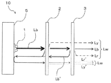
- FIG. 2 is a schematic cross-sectional view illustrating a state of wavelength conversion of light in the light emitting device of FIG. 1. It is a schematic perspective view which shows the structure of 2nd Embodiment of the light-emitting device which concerns on this invention.
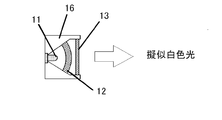
- 6 is a schematic cross-sectional view showing a configuration of a pseudo white LED light-emitting device for evaluation of Example 2.
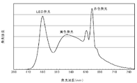
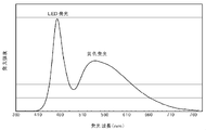
- FIG. It is a figure which shows the emission spectrum of the light-emitting device of Example 3-2. It is a figure which shows the emission spectrum of the light-emitting device of the comparative example 3.
- 10 is a perspective image of light emission states of wavelength conversion members of Example 3-2 and Comparative Example 3.
- the wavelength conversion member according to the present invention is a polyolefin, polystyrene, styrene copolymer, fluororesin, acrylic resin, nylon, polyester resin, polycarbonate in which a predetermined double fluoride phosphor is dispersed in a content of 30% by mass or less. It is a resin molding of one or more thermoplastic resins selected from the group of resins, vinyl chloride resins and polyether resins.
- the double fluoride phosphor used in the present invention has the following formula (1): A 2 (M 1-x Mn x ) F 6 (1) Wherein M is one or more tetravalent elements selected from Si, Ti, Zr, Hf, Ge and Sn, A is selected from Li, Na, K, Rb and Cs, and at least Na and And / or one or more alkali metals containing K, and x is 0.001 to 0.3, preferably 0.001 to 0.1.) It is a red phosphor represented by
- This phosphor is a manganese-activated bifluoride phosphor having a structure in which a part of the constituent elements of the double fluoride represented by A 2 MF 6 is substituted with manganese.
- the activator manganese is not particularly limited, but is obtained by substituting manganese for the tetravalent element site represented by A 2 MF 6, that is, a tetravalent element. Those substituted as manganese (Mn 4+ ) are preferred. In this case, it may be expressed as A 2 MF 6 : Mn 4+ .
- the double fluoride phosphor is particularly preferably manganese-activated potassium silicofluoride represented by K 2 (Si 1-x Mn x ) F 6 (x is the same as above).
- Such a manganese-activated bifluoride phosphor is excited by blue light having a wavelength of 420 to 490 nm, preferably 440 to 470 nm, and has a light emission peak or a maximum light emission peak within a wavelength range of 600 to 660 nm. To emit.
- the double fluoride phosphor represented by the above formula (1) may be produced by a conventionally known method.
- a metal fluoride raw material is dissolved or dispersed in hydrofluoric acid and heated to evaporate. It is good to use what was obtained by making it dry.
- the particle size D50 of 50% cumulative volume in the particle size distribution is 2 ⁇ m or more and 200 ⁇ m or less, preferably 10 ⁇ m or more and 60 ⁇ m or less.
- the D50 value is less than 2 ⁇ m, the light emission efficiency as a phosphor is lowered.
- the phosphor particles are large, there is essentially no problem with light emission.
- defects such as non-uniform distribution of the phosphor are likely to occur. The following are easy to use.
- the particle size measurement method in the present invention is, for example, a dry laser diffraction scattering method in which the target powder is sprayed in the air or dispersed and suspended, and laser light is irradiated to obtain the particle size from the diffraction pattern. It is preferable because it is not affected by humidity and can evaluate particle size distribution.
- the content of the manganese-activated bifluoride phosphor in the wavelength conversion member of the present invention varies depending on the thickness of the conversion member and the target color reproducibility, but is preferably 0.1% by mass or more, more preferably 2% by mass. Or more, more preferably 3% by mass or more, particularly preferably 5% by mass or more, and 30% by mass or less, preferably 15% by mass or less, more preferably 12% by mass or less, and further preferably 10% by mass or less. .
- the phosphor content exceeds 30% by mass, friction and wear between the fluorescent powder during kneading and the kneading screw of the molding machine increase. As a result, in the resin-encapsulated phosphor (wavelength conversion member) Discoloration will occur.
- the content is excessively high, the fluorescent powder partially aggregates in the sealing resin, and the light emission distribution in the resin-encapsulated fluorescent material becomes non-uniform.
- the content is less than 2% by mass, the light emission amount of red light is small and the effect of improving the color rendering properties may be lowered.
- the content is desirably 2% by mass or more.
- thermoplastic resin having high chemical resistance to alkali and excellent moisture resistance, and molding temperature (practical environment). We have made extensive studies on light transmission, moisture resistance, and heat resistance.
- a wavelength conversion member which is a resin-encapsulated fluorescent material, was prototyped using various thermoplastic resin materials, and the possibility of mixing manganese-activated bifluoride phosphors, optical characteristics, and moisture resistance were examined.
- a polyolefin, polystyrene or styrene copolymer, particularly polypropylene and / or polystyrene, especially polypropylene is used as the thermoplastic resin, mixing with the phosphor is possible, and the resin and the phosphor are decomposed.
- the knowledge that there was little deterioration was acquired.
- investigations were also made on fluororesin, acrylic resin, nylon (polyamide resin), polyester resin, polycarbonate resin, vinyl chloride resin, and polyether resin, and it was confirmed that they could be used as wavelength conversion members.
- thermoplastic resin used in the present invention polyolefins such as polyethylene and polypropylene, polystyrenes such as general-purpose polystyrene (GPPS), styrene / maleic acid copolymer, styrene / methyl methacrylate copolymer, Examples include styrene copolymers such as acrylonitrile / butadiene / styrene copolymer (ABS), and other examples include fluororesin, acrylic resin, nylon, polyester resin, polycarbonate resin, vinyl chloride resin, and polyether resin. 1 type (s) or 2 or more types selected from among them are used.
- GPPS general-purpose polystyrene
- ABS acrylonitrile / butadiene / styrene copolymer
- fluororesin acrylic resin, nylon, polyester resin, polycarbonate resin, vinyl chloride resin, and polyether resin. 1 type (s) or 2 or more types selected from among them are
- the thermoplastic resin used by this invention is a thermoplastic resin containing 40 mass% or more of polypropylene and / or polystyrene, especially polypropylene.
- the polypropylene may be any of a homopolymer, a block copolymer, and a random copolymer, but the copolymer is preferably a copolymer with ethylene.
- a random copolymer type ethylene copolymer containing a small amount of 2% to 6% by mass in the copolymer is preferable, and a melt flow rate (MFR) defined by JIS K 7210 is about 5 to 30 g / 10 min. Those that can be injection molded are more preferred.
- the molding method is not particularly limited, but injection molding that can be molded in a short time is more preferable.
- the wavelength conversion member of the present invention as in the case of the conventional thermoplastic material, 0.1 to 0 using an antioxidant, a light stabilizer, a stabilizer including an ultraviolet absorber and a molding lubricant as an auxiliary agent. It can mix
- a heavy metal deactivator may be added with a maximum of 0.3% by mass as a guide.
- a light diffusing agent is mixed as an aid for improving the diffusibility of light passing through the member.
- the light diffusing agent include inorganic ceramic powders such as talc, aluminum oxide, silicon oxide, aluminum silicate, and yttrium oxide. Among them, aluminum oxide powder or silicon oxide having high transparency and low loss of transmitted light. Powder is preferred.
- the particle size D50 value of the light diffusing agent is preferably 0.1 ⁇ m or more and 20 ⁇ m or less.
- the efficacy as a light diffusing agent may be lowered.
- the blending amount of the light diffusing agent is preferably 0.05 to 5% by mass, more preferably 0.05 to 1.5% by mass, and still more preferably 0.1 to 0.5% by mass. If the blending amount is less than 0.05% by mass, the light diffusion effect may not be sufficient, and if it exceeds 5% by mass, the light transmittance of the wavelength conversion member may be lowered.
- the above thermoplastic resin, manganese-activated bifluoride phosphor, and other auxiliaries are used as raw materials, mixed in a mixer, and made into an arbitrary shape according to the application.
- Thermoforming For example, it may be molded into a target shape suitable for the wavelength conversion member of the light emitting device at the time of mixing, or once molded into a pellet shape, when necessary, the wavelength conversion of the target shape from this pellet shape You may shape
- the average thickness of the wavelength conversion member corresponds to the required wavelength conversion performance (the amount of light in the red wavelength region that is absorbed and emitted with respect to the amount of incident blue excitation light, the transmittance of blue excitation light, etc.). Thus, it is determined from the relationship with the content of the manganese activated double fluoride phosphor, and for example, 0.5 to 5 mm is preferable.
- the wavelength conversion member thus obtained becomes a resin molded body in which a manganese-activated bifluoride phosphor is sealed with a predetermined thermoplastic resin, and the moisture resistance is remarkably improved. Further, the wavelength converting member optically emits fluorescence in the red wavelength region of about 600 to 660 nm when excited with blue light having a wavelength of 420 to 490 nm. Therefore, the wavelength converting member of the present invention containing a predetermined manganese-activated bifluoride Is applied to the light emitting device, a red wavelength component can be easily added to the emission spectrum, and the color rendering properties of the light emitting device, in particular, the average color rendering index Ra and the special color rendering index ⁇ R9 can be expected.
- the manganese-activated bifluoride phosphor has a relatively small absorption coefficient for blue light having a wavelength of 420 to 490 nm, and therefore has a characteristic that blue light is likely to enter the inside of the wavelength conversion member. Yes. For this reason, only the portion where the blue light is incident does not emit light in the wavelength conversion member, but the entire wavelength conversion member emits light, that is, a light emission source in a wide range according to the shape and size of the wavelength conversion member. In particular, it is suitable for a surface emitting light emitting device.
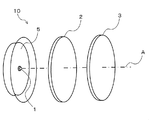
- FIG. 1 is a perspective view showing a configuration of a light emitting device according to a first embodiment of the present invention.
- a light emitting device 10 according to the present invention includes an LED light source 1 that emits blue light, and the above-described multifluoride phosphor that is disposed on the optical axis A of the LED light source 1.
- System wavelength conversion member, green wavelength conversion member, etc. 2.
- the LED light source 1 needs to contain the emitted light which can excite the fluorescent substance contained in all the wavelength conversion members 2 and 3 arrange
- the LED light source 1 is preferably composed of a plurality of LED chips for LED illumination.
- the chromaticity of the emitted light of the light emitting device 10 can be adjusted by the thicknesses of the wavelength conversion members 2 and 3, the phosphor content, the arrangement of the LED light source 1 on the optical axis, and the like.
- the wavelength conversion member 3 of the present invention is arranged in this order, One mode for obtaining white light with high color rendering properties will be described.
- the other wavelength conversion member 2 is a resin molding in which a yellow phosphor or a green phosphor is dispersed.
- a yellow or green wavelength conversion member in which a phosphor such as SiAlON: Eu 2+ is kneaded into a thermoplastic resin is preferable.
- the phosphor content in the other wavelength conversion member 2 is determined in consideration of the amount of incident blue light, the amount of light emitted in the yellow wavelength region, the transmittance of blue light, and the like.
- Y 3 Al 5 O 12 In the case of a 2 mm-thick plate material kneaded with Ce 3+ phosphor, the kneading concentration is preferably 0.2 to 5% by mass, and more preferably 1 to 4% by mass.
- the wavelength conversion member 3 is the wavelength conversion member of the present invention described above, and has a shape in which light from the LED light source 1 and the wavelength conversion member 2 is incident and light is efficiently emitted as a light emitting device. These wavelength conversion members 2 and 3 are preferably independent members that can be handled independently in the light emitting device 10.
- the shape of the wavelength conversion members 2 and 3 is not limited to the disk shape shown in FIG. 1, and may be a curved surface such as an incandescent light bulb or other shapes.
- the wavelength conversion member 3 has an excitation light transmittance of a wavelength of 420 to 490 nm of preferably 20% or more and 90% or less, and more preferably 30% or more and 70% or less. If the excitation light transmittance is less than 20%, the blue light emitted from the light emitting device may be insufficient, and the color balance may be deteriorated. If it exceeds 90%, the red light may be insufficient, and the effect of improving the color rendering property may not be expected. is there.
- the distance between the wavelength conversion member 3 and the LED light source 1 is preferably 2 to 100 mm, more preferably 5 to 10 mm. Although it can be used even when the above range is exceeded, if the distance is less than 2 mm, the wavelength conversion member may be deteriorated due to the heat effect from the LED light source 1, and if it exceeds 100 mm, the wavelength conversion member may be too large. is there.
- the blue light Lb when the blue light Lb is emitted from the LED light source 1, the blue light Lb first enters the other wavelength conversion member 2, and a part of the blue light Lb is generated.
- the yellow light Ly and the remaining blue light Lb are incident on the wavelength conversion member 3, and a part of the remaining blue light Lb is absorbed by the red phosphor included in the wavelength conversion member 3, and includes light including a red wavelength region (
- the light is converted into Lr (referred to herein as red light) and emitted together with the yellow light Ly that has passed through the wavelength conversion member 3 and the remaining blue light Lb.
- red light referred to herein as red light
- both phosphors in the wavelength conversion members 2 and 3 are configured to sequentially excite excitation light from the same LED light source 1, so that a plurality of white LED light sources are used. There is no difference in emission color due to variations in LED output as in the light emitting device based, and chromaticity is stable and uniform light emission is obtained. Further, according to the light emitting device 10 of the present invention, the wavelength conversion members 2 and 3 having the phosphor content adjusted in correspondence with the light emission of the target chromaticity at the final stage of the assembly of the light emitting device 10 are provided. Assembling is possible, and light emission toning with a high degree of freedom is possible by simple adjustment.
- the wavelength conversion member 3 of the present invention transmits most of light in the yellow wavelength region (or green wavelength region), the light control of the light emitting device 10 is easy. Further, since the wavelength conversion members 2 and 3 are spatially independent from the LED light source (light emitting chip) 1, the wavelength conversion members 2 and 3 are unlikely to become high temperature, and the characteristics of the contained phosphor are stable and long. Life is reached.
- the arrangement order of the wavelength conversion members 2 and 3 on the optical axis of the LED light source 1 may be changed, and the wavelength conversion member 3 of the present invention and the other wavelength conversion member 2 may be arranged in this order from the LED light source 1 side. .
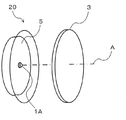
- FIG. 3 is a perspective view showing the configuration of the light emitting device according to the second embodiment of the present invention.
- the light emitting device 20 according to the present invention is disposed on the LED light source 1A that emits pseudo white light including a blue wavelength component and the optical axis A of the LED light source 1A.
- the wavelength conversion member 3 is provided.
- the LED light source 1A emits pseudo white light in which a blue LED surface emitting blue light having a wavelength of 420 to 490 nm, preferably 440 to 470 nm, is coated with a resin paint containing a yellow phosphor or a green phosphor. Light source.
- the wavelength conversion member 3 and the reflection plate 5 are the same as those in the first embodiment.
- the pseudo white light when the pseudo white light is emitted from the LED light source 1A, the pseudo white light is incident on the wavelength conversion member 3, and part of the blue light in the pseudo white light is included in the wavelength conversion member 3. It is converted into red light by the red phosphor. As a result, white light with high color rendering properties can be obtained.
- a part of the pseudo white light from the LED light source 1A is configured to excite the phosphor in the wavelength conversion member 3 as excitation light, and thus is based on a plurality of LED light sources.
- the wavelength converting member 3 for red wavelength is independent from the wavelength converting portion of the LED light source 1A.
- the wavelength conversion member 3 having a predetermined phosphor content may be assembled in correspondence with light emission of chromaticity, and light emission toning with a high degree of freedom is possible with simple adjustment.
- the wavelength conversion member 3 is spatially independent from and separated from the LED light source (light emitting chip) 1A, the wavelength conversion member 3 is unlikely to become high temperature, the characteristics of the contained phosphor are stable, and the life is long. It becomes.
- each component can be changed without changing the gist of the present invention, and the present invention is not limited to the embodiment described above.
- the LED light source 1A shown in FIG. 3 is a blue LED
- the blue light is incident on the wavelength conversion member 3, and a part of the blue light is included in the wavelength conversion member 3.
- the red phosphor is converted into red light, and light in which blue light and red light are mixed is emitted.
- the light emitting device of the present invention is suitable as a remote phosphor type light emitting device in which a wavelength conversion member is disposed at a location away from a blue LED light source via a gas layer or a vacuum layer.
- the remote phosphor has a light distribution characteristic different from that of a general LED light-emitting device, such as a surface emission and a large emission angle, and is particularly suitable for a lighting fixture that illuminates a wide area.
- Example 1 After the transparent polypropylene pellets were dried at 90 ° C. for 3 hours, stearyl- ⁇ - (3,5-t-butyl-4-hydroxyphenyl) propionate, cyclic neopentanetetraylbis (2,6- Di-t-butyl-4-methylphenyl) phosphite, bis (2,2,6,6-tetramethyl-4-piperidyl) sebacate, 2- (2′-hydroxy-3′-tert-butyl-5 ′) -Methylphenyl) -5-chlorobenzotriazole and calcium stearate added to 0.1% by weight, 0.1% by weight, 0.3% by weight, 0.1% by weight and 0.05% by weight, respectively And mixed with stirring.
- the obtained K 2 (Si 0.97 Mn 0.03 ) F 6 -containing polypropylene pellets were molded into a plate-like member having a thickness of 2 mm and a diameter of 20 mm by a 20 t horizontal injection molding machine.
- the quantum efficiency measurement system QE1100 (manufactured by Otsuka Electronics Co., Ltd.) evaluates the transmittance of the excitation light and the external quantum efficiency of red light emission obtained by converting the wavelength of the excitation light. Went. Furthermore, the presence or absence of light emission unevenness when irradiated with blue light was visually observed from the back side. The above evaluation results are shown in Table 1.
- Example 1-1 the phosphor content in Example 1-1 was low, so that most of the light was transmitted and the light emitted from the wavelength conversion member was negligible. As the content of the red phosphor increased, the transmittance of the excitation light decreased and the red light emission became stronger. Moreover, although the presence or absence of the light emission nonuniformity by irradiating blue light was observed visually from the back side, the light emission nonuniformity was not recognized. In Comparative Example 1, strong red light emission was observed, but light emission unevenness was observed in the light and dark parts.
- Example 2 A plate-like wavelength conversion member having a red phosphor content of 5% by mass and 10% by mass was produced in the same manner as in Example 1. Moreover, the same wavelength conversion member containing 5 mass% of YAG: Ce3 + fluorescent substance was produced, and the light-emitting device of the structure shown in FIG. 4 was produced combining these.
- 11 is a blue LED light source
- 12 is a yellow wavelength conversion member
- 13 is a red wavelength conversion member
- 16 is a package.
- a blue light source using a 2W blue LED chip manufactured by Cree that emits 450 nm light was used as the excitation light. Table 2 shows combinations of wavelength conversion members of the respective light emitting devices.
- the color temperature, average color rendering index Ra, and special color rendering index ⁇ R9 for each light emitting device were measured using a spectral irradiance meter CL-500A (manufactured by Konica Minolta Optics). For comparison, a light-emitting device that does not use the red wavelength conversion member was also prototyped and evaluated. The results are summarized in Table 2.
- the color temperature of the light-emitting device can be changed by adjusting the amount and thickness of the phosphor contained in the wavelength conversion member, and the average color rendering index Ra and the special color rendering index by using the red wavelength conversion member It can be seen that ⁇ R9 is improved.
- Example 3 A light emitting device was manufactured under the following conditions. Using a twin-screw extruder, the concentration of the transparent polypropylene pellets, K 2 (Si 0.97 Mn 0.03 ) used in Example 1 and mixed and the F 6 phosphor, K 2 (Si 0.97 Mn 0.03 ) F 6 phosphor Thus, a K 2 (Si 0.97 Mn 0.03 ) F 6 phosphor-containing polypropylene pellet containing 2.5% by mass and 10% by mass was obtained.
- the blue LED light emitting device (GL-RB100 (using 6 x 2W blue LED chips XT-E Royal Blue manufactured by Cree), manufactured by Hino Electronics Co., Ltd.))
- GL-RB100 using 6 x 2W blue LED chips XT-E Royal Blue manufactured by Cree), manufactured by Hino Electronics Co., Ltd.
- the combination of the wavelength conversion members as shown in Table 3, the first wavelength conversion member and the second wavelength conversion member are arranged from the LED light emitting device side, and the yellow wavelength conversion member and the red wavelength conversion member are arranged in this order. What was arranged in the order of the wavelength conversion member and the yellow wavelength conversion member was produced by changing the combination of the phosphor contents, and further only the yellow wavelength conversion member (phosphor content 4 mass%) was arranged. Also made.
- the spectrum of the light emitting device using the wavelength conversion member of the present invention has an emission peak at a wavelength of 600 nm or more, which is the average color rendering index Ra.
- the special color rendering index ⁇ R9 is improved.
- the average color rendering index Ra and the special color rendering evaluation number ⁇ R9 of the LED light emitting device using only the yellow wavelength conversion member are greatly improved. be able to. Further, even after the LED light emitting device is assembled, it is possible to adjust the chromaticity and color rendering of the emitted light simply by exchanging the wavelength conversion member.
- a plate-shaped wavelength conversion member having a thickness of 2 mm and a 40 mm square was prepared for the red wavelength conversion member of Example 3-2 and the yellow wavelength conversion member of Comparative Example 3 using the pellets, and the blue LED Light from (wavelength 460 nm) was irradiated from a direction perpendicular to the 40 mm square surface of the wavelength conversion member, and the state of light emission of the wavelength conversion member viewed from the back side of the irradiation surface was visually confirmed.
- a perspective view of the light emission state is shown in FIG. In the case of the yellow wavelength conversion member of Comparative Example 3 in FIG. 7B, only the portion irradiated with the blue light that is the excitation light (the right side portion in the drawing) emits light and shines.
- the peripheral portion (from the center to the left in the figure) emits light as well as the portion irradiated with the blue light that is the excitation light. It can be seen that the light emission range of the wavelength conversion member is wide.
Landscapes
- Chemical & Material Sciences (AREA)
- Engineering & Computer Science (AREA)
- Materials Engineering (AREA)
- Organic Chemistry (AREA)
- Inorganic Chemistry (AREA)
- Microelectronics & Electronic Packaging (AREA)
- Manufacturing & Machinery (AREA)
- Computer Hardware Design (AREA)
- Power Engineering (AREA)
- Led Device Packages (AREA)
- Luminescent Compositions (AREA)
- Optical Filters (AREA)
Priority Applications (5)
| Application Number | Priority Date | Filing Date | Title |
|---|---|---|---|
| KR1020157020018A KR102087270B1 (ko) | 2012-12-28 | 2013-12-26 | 파장 변환 부재 및 발광 장치 |
| US14/654,901 US9982189B2 (en) | 2012-12-28 | 2013-12-26 | Wavelength conversion member and light-emitting device |
| JP2014554516A JP5983775B2 (ja) | 2012-12-28 | 2013-12-26 | 波長変換部材及び発光装置 |
| EP13868903.9A EP2940745B1 (de) | 2012-12-28 | 2013-12-26 | Wellenlängenumwandlungselement und lichtemittierende vorrichtung |
| CN201380068227.3A CN104885238B (zh) | 2012-12-28 | 2013-12-26 | 波长转换部件和发光装置 |
Applications Claiming Priority (2)
| Application Number | Priority Date | Filing Date | Title |
|---|---|---|---|
| JP2012-287314 | 2012-12-28 | ||
| JP2012287314 | 2012-12-28 |
Publications (1)
| Publication Number | Publication Date |
|---|---|
| WO2014104147A1 true WO2014104147A1 (ja) | 2014-07-03 |
Family
ID=51021223
Family Applications (1)
| Application Number | Title | Priority Date | Filing Date |
|---|---|---|---|
| PCT/JP2013/084777 WO2014104147A1 (ja) | 2012-12-28 | 2013-12-26 | 波長変換部材及び発光装置 |
Country Status (7)
| Country | Link |
|---|---|
| US (1) | US9982189B2 (de) |
| EP (1) | EP2940745B1 (de) |
| JP (2) | JP5983775B2 (de) |
| KR (1) | KR102087270B1 (de) |
| CN (1) | CN104885238B (de) |
| TW (1) | TWI589674B (de) |
| WO (1) | WO2014104147A1 (de) |
Cited By (4)
| Publication number | Priority date | Publication date | Assignee | Title |
|---|---|---|---|---|
| CN105895779A (zh) * | 2015-02-16 | 2016-08-24 | Lg伊诺特有限公司 | 发光器件封装和包含发光器件封装的照明装置 |
| WO2017034355A1 (ko) * | 2015-08-25 | 2017-03-02 | 엘지이노텍 주식회사 | 적색 형광체 및 이를 포함하는 발광장치 |
| KR20170024413A (ko) * | 2015-08-25 | 2017-03-07 | 엘지이노텍 주식회사 | 적색 형광체 및 이를 포함하는 발광장치 |
| US20180312751A1 (en) * | 2015-11-26 | 2018-11-01 | General Electric Company | Processes for synthesizing red-emitting phosphors and related red-emitting phosphors |
Families Citing this family (6)
| Publication number | Priority date | Publication date | Assignee | Title |
|---|---|---|---|---|
| KR101778848B1 (ko) * | 2015-08-21 | 2017-09-14 | 엘지전자 주식회사 | 발광소자 패키지 어셈블리 및 이의 제조 방법 |
| US10113070B2 (en) * | 2015-11-04 | 2018-10-30 | Ppg Industries Ohio, Inc. | Pretreatment compositions and methods of treating a substrate |
| JP6541638B2 (ja) * | 2016-12-28 | 2019-07-10 | 堺化学工業株式会社 | 蛍光体含有多層膜シート、並びに発光装置 |
| JP2019015848A (ja) * | 2017-07-06 | 2019-01-31 | 株式会社タムラ製作所 | 波長変換部材及びその製造方法 |
| JP7004694B2 (ja) | 2019-11-05 | 2022-01-21 | 東洋スチレン株式会社 | 良色相の成形品およびその製造方法 |
| JP2021105712A (ja) * | 2019-12-26 | 2021-07-26 | 住友化学株式会社 | 表示装置 |
Citations (6)
| Publication number | Priority date | Publication date | Assignee | Title |
|---|---|---|---|---|
| JP2010045328A (ja) * | 2008-07-18 | 2010-02-25 | Sharp Corp | 発光装置および発光装置の製造方法 |
| WO2010095395A1 (ja) * | 2009-02-18 | 2010-08-26 | 三井金属鉱業株式会社 | 蛍光体含有樹脂組成物及び蛍光シート |
| JP2010209311A (ja) * | 2008-09-05 | 2010-09-24 | Mitsubishi Chemicals Corp | 蛍光体及びその製造方法と、その蛍光体を用いた蛍光体含有組成物及び発光装置、並びに、その発光装置を用いた画像表示装置及び照明装置 |
| JP2011029497A (ja) * | 2009-07-28 | 2011-02-10 | Mitsubishi Chemicals Corp | 白色発光装置およびそれを用いた照明装置 |
| JP2012104814A (ja) * | 2010-10-15 | 2012-05-31 | Mitsubishi Chemicals Corp | 白色発光装置及び照明器具 |
| JP2012224536A (ja) | 2011-04-08 | 2012-11-15 | Shin-Etsu Chemical Co Ltd | 複フッ化物及び複フッ化物蛍光体の製造方法 |
Family Cites Families (10)
| Publication number | Priority date | Publication date | Assignee | Title |
|---|---|---|---|---|
| KR101559603B1 (ko) * | 2008-02-07 | 2015-10-12 | 미쓰비시 가가꾸 가부시키가이샤 | 반도체 발광 장치, 백라이트, 컬러 화상 표시 장치, 및 그들에 사용하는 형광체 |
| JP2010023880A (ja) | 2008-07-18 | 2010-02-04 | Sharp Corp | 蛍光体混練物包装容器 |
| JP5754374B2 (ja) | 2009-03-31 | 2015-07-29 | 三菱化学株式会社 | 蛍光体、蛍光体の製造方法、蛍光体含有組成物、発光装置、照明装置及び画像表示装置 |
| JP5423120B2 (ja) * | 2009-04-17 | 2014-02-19 | 三菱化学株式会社 | 半導体発光装置 |
| TW201140890A (en) * | 2009-12-17 | 2011-11-16 | Koninkl Philips Electronics Nv | Lighting device with light source and wavelength converting element |
| EP2540798A4 (de) | 2010-02-26 | 2014-04-30 | Mitsubishi Chem Corp | Halophosphatphosphor und weisslicht-ausgabevorrichtung |
| US20120267999A1 (en) | 2010-02-26 | 2012-10-25 | Mitsubishi Chemical Corporation | Halophosphate phosphor and white light-emitting device |
| JP5519440B2 (ja) | 2010-08-03 | 2014-06-11 | 日東電工株式会社 | 発光装置 |
| JP2013045896A (ja) | 2011-08-24 | 2013-03-04 | Mitsubishi Chemicals Corp | 発光装置 |
| JP2012060192A (ja) | 2011-12-26 | 2012-03-22 | Toshiba Corp | 発光装置、その製造方法および発光装置製造装置 |
-
2013
- 2013-12-26 EP EP13868903.9A patent/EP2940745B1/de not_active Expired - Fee Related
- 2013-12-26 KR KR1020157020018A patent/KR102087270B1/ko active IP Right Grant
- 2013-12-26 JP JP2014554516A patent/JP5983775B2/ja not_active Expired - Fee Related
- 2013-12-26 WO PCT/JP2013/084777 patent/WO2014104147A1/ja active Application Filing
- 2013-12-26 US US14/654,901 patent/US9982189B2/en active Active
- 2013-12-26 CN CN201380068227.3A patent/CN104885238B/zh not_active Expired - Fee Related
- 2013-12-27 TW TW102148738A patent/TWI589674B/zh not_active IP Right Cessation
-
2016
- 2016-04-05 JP JP2016075852A patent/JP6197908B2/ja active Active
Patent Citations (6)
| Publication number | Priority date | Publication date | Assignee | Title |
|---|---|---|---|---|
| JP2010045328A (ja) * | 2008-07-18 | 2010-02-25 | Sharp Corp | 発光装置および発光装置の製造方法 |
| JP2010209311A (ja) * | 2008-09-05 | 2010-09-24 | Mitsubishi Chemicals Corp | 蛍光体及びその製造方法と、その蛍光体を用いた蛍光体含有組成物及び発光装置、並びに、その発光装置を用いた画像表示装置及び照明装置 |
| WO2010095395A1 (ja) * | 2009-02-18 | 2010-08-26 | 三井金属鉱業株式会社 | 蛍光体含有樹脂組成物及び蛍光シート |
| JP2011029497A (ja) * | 2009-07-28 | 2011-02-10 | Mitsubishi Chemicals Corp | 白色発光装置およびそれを用いた照明装置 |
| JP2012104814A (ja) * | 2010-10-15 | 2012-05-31 | Mitsubishi Chemicals Corp | 白色発光装置及び照明器具 |
| JP2012224536A (ja) | 2011-04-08 | 2012-11-15 | Shin-Etsu Chemical Co Ltd | 複フッ化物及び複フッ化物蛍光体の製造方法 |
Non-Patent Citations (1)
| Title |
|---|
| See also references of EP2940745A4 |
Cited By (8)
| Publication number | Priority date | Publication date | Assignee | Title |
|---|---|---|---|---|
| CN105895779A (zh) * | 2015-02-16 | 2016-08-24 | Lg伊诺特有限公司 | 发光器件封装和包含发光器件封装的照明装置 |
| EP3057131B1 (de) * | 2015-02-16 | 2020-06-17 | LG Innotek Co., Ltd. | Gehäuseverpackung einer lichtemittierenden vorrichtung und beleuchtungsvorrichtung damit |
| JP7113407B2 (ja) | 2015-02-16 | 2022-08-05 | スージョウ レキン セミコンダクター カンパニー リミテッド | 発光素子パッケージ及びそれを含む照明システム |
| WO2017034355A1 (ko) * | 2015-08-25 | 2017-03-02 | 엘지이노텍 주식회사 | 적색 형광체 및 이를 포함하는 발광장치 |
| KR20170024413A (ko) * | 2015-08-25 | 2017-03-07 | 엘지이노텍 주식회사 | 적색 형광체 및 이를 포함하는 발광장치 |
| KR102472340B1 (ko) * | 2015-08-25 | 2022-11-30 | 쑤저우 레킨 세미컨덕터 컴퍼니 리미티드 | 적색 형광체 및 이를 포함하는 발광장치 |
| US20180312751A1 (en) * | 2015-11-26 | 2018-11-01 | General Electric Company | Processes for synthesizing red-emitting phosphors and related red-emitting phosphors |
| US10920136B2 (en) * | 2015-11-26 | 2021-02-16 | Current Lighting Solutions, Llc | Processes for synthesizing red-emitting phosphors and related red-emitting phosphors |
Also Published As
| Publication number | Publication date |
|---|---|
| EP2940745A4 (de) | 2016-06-29 |
| EP2940745A1 (de) | 2015-11-04 |
| TWI589674B (zh) | 2017-07-01 |
| JP5983775B2 (ja) | 2016-09-06 |
| US20150340571A1 (en) | 2015-11-26 |
| CN104885238A (zh) | 2015-09-02 |
| KR20150099843A (ko) | 2015-09-01 |
| JP2016170419A (ja) | 2016-09-23 |
| JP6197908B2 (ja) | 2017-09-20 |
| CN104885238B (zh) | 2018-07-27 |
| TW201439278A (zh) | 2014-10-16 |
| JPWO2014104147A1 (ja) | 2017-01-12 |
| US9982189B2 (en) | 2018-05-29 |
| KR102087270B1 (ko) | 2020-03-10 |
| EP2940745B1 (de) | 2019-08-28 |
Similar Documents
| Publication | Publication Date | Title |
|---|---|---|
| JP6197908B2 (ja) | 発光装置 | |
| JP6079927B2 (ja) | 波長変換部材及び発光装置の作製方法 | |
| JP6101978B2 (ja) | 発光装置 | |
| JP6376225B2 (ja) | 波長変換部材及び発光装置 | |
| JP6098747B2 (ja) | 調整部品及び発光装置 |
Legal Events
| Date | Code | Title | Description |
|---|---|---|---|
| 121 | Ep: the epo has been informed by wipo that ep was designated in this application |
Ref document number: 13868903 Country of ref document: EP Kind code of ref document: A1 |
|
| ENP | Entry into the national phase |
Ref document number: 2014554516 Country of ref document: JP Kind code of ref document: A |
|
| WWE | Wipo information: entry into national phase |
Ref document number: 14654901 Country of ref document: US Ref document number: 2013868903 Country of ref document: EP |
|
| NENP | Non-entry into the national phase |
Ref country code: DE |
|
| ENP | Entry into the national phase |
Ref document number: 20157020018 Country of ref document: KR Kind code of ref document: A |