EP2940745A1 - Wellenlängenumwandlungselement und lichtemittierende vorrichtung - Google Patents
Wellenlängenumwandlungselement und lichtemittierende vorrichtung Download PDFInfo
- Publication number
- EP2940745A1 EP2940745A1 EP13868903.9A EP13868903A EP2940745A1 EP 2940745 A1 EP2940745 A1 EP 2940745A1 EP 13868903 A EP13868903 A EP 13868903A EP 2940745 A1 EP2940745 A1 EP 2940745A1
- Authority
- EP
- European Patent Office
- Prior art keywords
- light
- wavelength conversion
- conversion member
- phosphor
- resin
- Prior art date
- Legal status (The legal status is an assumption and is not a legal conclusion. Google has not performed a legal analysis and makes no representation as to the accuracy of the status listed.)
- Granted
Links
- 238000006243 chemical reaction Methods 0.000 title claims abstract description 147
- 229920005989 resin Polymers 0.000 claims abstract description 36
- 239000011347 resin Substances 0.000 claims abstract description 36
- 229920005992 thermoplastic resin Polymers 0.000 claims abstract description 29
- 239000002245 particle Substances 0.000 claims abstract description 26
- 239000004793 Polystyrene Substances 0.000 claims abstract description 13
- 229920002223 polystyrene Polymers 0.000 claims abstract description 13
- 229920001577 copolymer Polymers 0.000 claims abstract description 10
- 229920005668 polycarbonate resin Polymers 0.000 claims abstract description 7
- 239000004431 polycarbonate resin Substances 0.000 claims abstract description 7
- 229920000178 Acrylic resin Polymers 0.000 claims abstract description 6
- 239000004925 Acrylic resin Substances 0.000 claims abstract description 6
- 239000004721 Polyphenylene oxide Substances 0.000 claims abstract description 6
- PPBRXRYQALVLMV-UHFFFAOYSA-N Styrene Natural products C=CC1=CC=CC=C1 PPBRXRYQALVLMV-UHFFFAOYSA-N 0.000 claims abstract description 6
- BZHJMEDXRYGGRV-UHFFFAOYSA-N Vinyl chloride Chemical compound ClC=C BZHJMEDXRYGGRV-UHFFFAOYSA-N 0.000 claims abstract description 6
- 229920001778 nylon Polymers 0.000 claims abstract description 6
- 239000004645 polyester resin Substances 0.000 claims abstract description 6
- 229920001225 polyester resin Polymers 0.000 claims abstract description 6
- 229920000570 polyether Polymers 0.000 claims abstract description 6
- 229920000098 polyolefin Polymers 0.000 claims abstract description 6
- 229910052783 alkali metal Inorganic materials 0.000 claims abstract description 5
- 150000001340 alkali metals Chemical class 0.000 claims abstract description 5
- 229910052792 caesium Inorganic materials 0.000 claims abstract description 5
- 229910052732 germanium Inorganic materials 0.000 claims abstract description 5
- 229910052735 hafnium Inorganic materials 0.000 claims abstract description 5
- 229910052744 lithium Inorganic materials 0.000 claims abstract description 5
- 229910052700 potassium Inorganic materials 0.000 claims abstract description 5
- 229910052701 rubidium Inorganic materials 0.000 claims abstract description 5
- 229910052710 silicon Inorganic materials 0.000 claims abstract description 5
- 229910052708 sodium Inorganic materials 0.000 claims abstract description 5
- 229910052718 tin Inorganic materials 0.000 claims abstract description 5
- 229910052719 titanium Inorganic materials 0.000 claims abstract description 5
- 229910052726 zirconium Inorganic materials 0.000 claims abstract description 5
- 230000001186 cumulative effect Effects 0.000 claims abstract description 4
- OAICVXFJPJFONN-UHFFFAOYSA-N Phosphorus Chemical compound [P] OAICVXFJPJFONN-UHFFFAOYSA-N 0.000 claims description 92
- 239000011572 manganese Substances 0.000 claims description 42
- XPIIDKFHGDPTIY-UHFFFAOYSA-N F.F.F.P Chemical compound F.F.F.P XPIIDKFHGDPTIY-UHFFFAOYSA-N 0.000 claims description 29
- -1 manganese-activated potassium Chemical class 0.000 claims description 26
- 239000004743 Polypropylene Substances 0.000 claims description 21
- 229920001155 polypropylene Polymers 0.000 claims description 21
- 229910052748 manganese Inorganic materials 0.000 claims description 20
- 230000003287 optical effect Effects 0.000 claims description 17
- 239000000463 material Substances 0.000 claims description 9
- 239000004677 Nylon Substances 0.000 claims description 4
- KRHYYFGTRYWZRS-UHFFFAOYSA-M Fluoride anion Chemical compound [F-] KRHYYFGTRYWZRS-UHFFFAOYSA-M 0.000 abstract description 6
- QHIWVLPBUQWDMQ-UHFFFAOYSA-N butyl prop-2-enoate;methyl 2-methylprop-2-enoate;prop-2-enoic acid Chemical compound OC(=O)C=C.COC(=O)C(C)=C.CCCCOC(=O)C=C QHIWVLPBUQWDMQ-UHFFFAOYSA-N 0.000 abstract 1
- NBVXSUQYWXRMNV-UHFFFAOYSA-N fluoromethane Chemical compound FC NBVXSUQYWXRMNV-UHFFFAOYSA-N 0.000 abstract 1
- 238000009877 rendering Methods 0.000 description 27
- PWHULOQIROXLJO-UHFFFAOYSA-N Manganese Chemical compound [Mn] PWHULOQIROXLJO-UHFFFAOYSA-N 0.000 description 17
- 230000000052 comparative effect Effects 0.000 description 15
- 230000005284 excitation Effects 0.000 description 14
- 239000008188 pellet Substances 0.000 description 12
- 238000000465 moulding Methods 0.000 description 10
- 238000002834 transmittance Methods 0.000 description 10
- 229910019901 yttrium aluminum garnet Inorganic materials 0.000 description 10
- LDXJRKWFNNFDSA-UHFFFAOYSA-N 2-(2,4,6,7-tetrahydrotriazolo[4,5-c]pyridin-5-yl)-1-[4-[2-[[3-(trifluoromethoxy)phenyl]methylamino]pyrimidin-5-yl]piperazin-1-yl]ethanone Chemical compound C1CN(CC2=NNN=C21)CC(=O)N3CCN(CC3)C4=CN=C(N=C4)NCC5=CC(=CC=C5)OC(F)(F)F LDXJRKWFNNFDSA-UHFFFAOYSA-N 0.000 description 6
- 230000000694 effects Effects 0.000 description 6
- 239000003795 chemical substances by application Substances 0.000 description 5
- 238000000295 emission spectrum Methods 0.000 description 5
- 238000000034 method Methods 0.000 description 5
- 238000003801 milling Methods 0.000 description 5
- 238000002156 mixing Methods 0.000 description 5
- 239000000843 powder Substances 0.000 description 5
- 229910052688 Gadolinium Inorganic materials 0.000 description 4
- 238000005286 illumination Methods 0.000 description 4
- 229910003564 SiAlON Inorganic materials 0.000 description 3
- 238000010521 absorption reaction Methods 0.000 description 3
- 239000000654 additive Substances 0.000 description 3
- 230000015572 biosynthetic process Effects 0.000 description 3
- 238000005516 engineering process Methods 0.000 description 3
- 238000001746 injection moulding Methods 0.000 description 3
- 238000003786 synthesis reaction Methods 0.000 description 3
- VZSRBBMJRBPUNF-UHFFFAOYSA-N 2-(2,3-dihydro-1H-inden-2-ylamino)-N-[3-oxo-3-(2,4,6,7-tetrahydrotriazolo[4,5-c]pyridin-5-yl)propyl]pyrimidine-5-carboxamide Chemical compound C1C(CC2=CC=CC=C12)NC1=NC=C(C=N1)C(=O)NCCC(N1CC2=C(CC1)NN=N2)=O VZSRBBMJRBPUNF-UHFFFAOYSA-N 0.000 description 2
- YLZOPXRUQYQQID-UHFFFAOYSA-N 3-(2,4,6,7-tetrahydrotriazolo[4,5-c]pyridin-5-yl)-1-[4-[2-[[3-(trifluoromethoxy)phenyl]methylamino]pyrimidin-5-yl]piperazin-1-yl]propan-1-one Chemical compound N1N=NC=2CN(CCC=21)CCC(=O)N1CCN(CC1)C=1C=NC(=NC=1)NCC1=CC(=CC=C1)OC(F)(F)F YLZOPXRUQYQQID-UHFFFAOYSA-N 0.000 description 2
- VGGSQFUCUMXWEO-UHFFFAOYSA-N Ethene Chemical compound C=C VGGSQFUCUMXWEO-UHFFFAOYSA-N 0.000 description 2
- 239000005977 Ethylene Substances 0.000 description 2
- KRHYYFGTRYWZRS-UHFFFAOYSA-N Fluorane Chemical compound F KRHYYFGTRYWZRS-UHFFFAOYSA-N 0.000 description 2
- VYPSYNLAJGMNEJ-UHFFFAOYSA-N Silicium dioxide Chemical compound O=[Si]=O VYPSYNLAJGMNEJ-UHFFFAOYSA-N 0.000 description 2
- 239000012752 auxiliary agent Substances 0.000 description 2
- 238000010276 construction Methods 0.000 description 2
- 238000010586 diagram Methods 0.000 description 2
- 238000011156 evaluation Methods 0.000 description 2
- 229910052733 gallium Inorganic materials 0.000 description 2
- 239000011521 glass Substances 0.000 description 2
- 238000002347 injection Methods 0.000 description 2
- 239000007924 injection Substances 0.000 description 2
- 229910052909 inorganic silicate Inorganic materials 0.000 description 2
- 238000005259 measurement Methods 0.000 description 2
- 239000000203 mixture Substances 0.000 description 2
- CRSOQBOWXPBRES-UHFFFAOYSA-N neopentane Chemical compound CC(C)(C)C CRSOQBOWXPBRES-UHFFFAOYSA-N 0.000 description 2
- TWNQGVIAIRXVLR-UHFFFAOYSA-N oxo(oxoalumanyloxy)alumane Chemical compound O=[Al]O[Al]=O TWNQGVIAIRXVLR-UHFFFAOYSA-N 0.000 description 2
- 229920005604 random copolymer Polymers 0.000 description 2
- 229910052814 silicon oxide Inorganic materials 0.000 description 2
- 239000000243 solution Substances 0.000 description 2
- 239000003381 stabilizer Substances 0.000 description 2
- 238000012360 testing method Methods 0.000 description 2
- 229910052727 yttrium Inorganic materials 0.000 description 2
- HMUNWXXNJPVALC-UHFFFAOYSA-N 1-[4-[2-(2,3-dihydro-1H-inden-2-ylamino)pyrimidin-5-yl]piperazin-1-yl]-2-(2,4,6,7-tetrahydrotriazolo[4,5-c]pyridin-5-yl)ethanone Chemical compound C1C(CC2=CC=CC=C12)NC1=NC=C(C=N1)N1CCN(CC1)C(CN1CC2=C(CC1)NN=N2)=O HMUNWXXNJPVALC-UHFFFAOYSA-N 0.000 description 1
- VAYOSLLFUXYJDT-RDTXWAMCSA-N Lysergic acid diethylamide Chemical compound C1=CC(C=2[C@H](N(C)C[C@@H](C=2)C(=O)N(CC)CC)C2)=C3C2=CNC3=C1 VAYOSLLFUXYJDT-RDTXWAMCSA-N 0.000 description 1
- MKYBYDHXWVHEJW-UHFFFAOYSA-N N-[1-oxo-1-(2,4,6,7-tetrahydrotriazolo[4,5-c]pyridin-5-yl)propan-2-yl]-2-[[3-(trifluoromethoxy)phenyl]methylamino]pyrimidine-5-carboxamide Chemical compound O=C(C(C)NC(=O)C=1C=NC(=NC=1)NCC1=CC(=CC=C1)OC(F)(F)F)N1CC2=C(CC1)NN=N2 MKYBYDHXWVHEJW-UHFFFAOYSA-N 0.000 description 1
- NIPNSKYNPDTRPC-UHFFFAOYSA-N N-[2-oxo-2-(2,4,6,7-tetrahydrotriazolo[4,5-c]pyridin-5-yl)ethyl]-2-[[3-(trifluoromethoxy)phenyl]methylamino]pyrimidine-5-carboxamide Chemical compound O=C(CNC(=O)C=1C=NC(=NC=1)NCC1=CC(=CC=C1)OC(F)(F)F)N1CC2=C(CC1)NN=N2 NIPNSKYNPDTRPC-UHFFFAOYSA-N 0.000 description 1
- AFCARXCZXQIEQB-UHFFFAOYSA-N N-[3-oxo-3-(2,4,6,7-tetrahydrotriazolo[4,5-c]pyridin-5-yl)propyl]-2-[[3-(trifluoromethoxy)phenyl]methylamino]pyrimidine-5-carboxamide Chemical compound O=C(CCNC(=O)C=1C=NC(=NC=1)NCC1=CC(=CC=C1)OC(F)(F)F)N1CC2=C(CC1)NN=N2 AFCARXCZXQIEQB-UHFFFAOYSA-N 0.000 description 1
- ABLZXFCXXLZCGV-UHFFFAOYSA-N Phosphorous acid Chemical compound OP(O)=O ABLZXFCXXLZCGV-UHFFFAOYSA-N 0.000 description 1
- 239000004698 Polyethylene Substances 0.000 description 1
- XBDQKXXYIPTUBI-UHFFFAOYSA-M Propionate Chemical compound CCC([O-])=O XBDQKXXYIPTUBI-UHFFFAOYSA-M 0.000 description 1
- 229920007962 Styrene Methyl Methacrylate Polymers 0.000 description 1
- YKTSYUJCYHOUJP-UHFFFAOYSA-N [O--].[Al+3].[Al+3].[O-][Si]([O-])([O-])[O-] Chemical compound [O--].[Al+3].[Al+3].[O-][Si]([O-])([O-])[O-] YKTSYUJCYHOUJP-UHFFFAOYSA-N 0.000 description 1
- 239000006096 absorbing agent Substances 0.000 description 1
- 239000004676 acrylonitrile butadiene styrene Substances 0.000 description 1
- 239000012190 activator Substances 0.000 description 1
- 238000007792 addition Methods 0.000 description 1
- 238000013019 agitation Methods 0.000 description 1
- 239000003963 antioxidant agent Substances 0.000 description 1
- 230000003078 antioxidant effect Effects 0.000 description 1
- XITRBUPOXXBIJN-UHFFFAOYSA-N bis(2,2,6,6-tetramethylpiperidin-4-yl) decanedioate Chemical compound C1C(C)(C)NC(C)(C)CC1OC(=O)CCCCCCCCC(=O)OC1CC(C)(C)NC(C)(C)C1 XITRBUPOXXBIJN-UHFFFAOYSA-N 0.000 description 1
- 229920001400 block copolymer Polymers 0.000 description 1
- OCWYEMOEOGEQAN-UHFFFAOYSA-N bumetrizole Chemical compound CC(C)(C)C1=CC(C)=CC(N2N=C3C=C(Cl)C=CC3=N2)=C1O OCWYEMOEOGEQAN-UHFFFAOYSA-N 0.000 description 1
- CJZGTCYPCWQAJB-UHFFFAOYSA-L calcium stearate Chemical compound [Ca+2].CCCCCCCCCCCCCCCCCC([O-])=O.CCCCCCCCCCCCCCCCCC([O-])=O CJZGTCYPCWQAJB-UHFFFAOYSA-L 0.000 description 1
- 239000008116 calcium stearate Substances 0.000 description 1
- 235000013539 calcium stearate Nutrition 0.000 description 1
- 239000000919 ceramic Substances 0.000 description 1
- 229910019990 cerium-doped yttrium aluminum garnet Inorganic materials 0.000 description 1
- 239000011248 coating agent Substances 0.000 description 1
- 238000000576 coating method Methods 0.000 description 1
- 239000000470 constituent Substances 0.000 description 1
- 125000004122 cyclic group Chemical group 0.000 description 1
- 238000012217 deletion Methods 0.000 description 1
- 230000037430 deletion Effects 0.000 description 1
- 238000009792 diffusion process Methods 0.000 description 1
- 230000008020 evaporation Effects 0.000 description 1
- 238000001704 evaporation Methods 0.000 description 1
- 229910052736 halogen Inorganic materials 0.000 description 1
- 150000002367 halogens Chemical class 0.000 description 1
- 238000010438 heat treatment Methods 0.000 description 1
- 229910001385 heavy metal Inorganic materials 0.000 description 1
- 229920001519 homopolymer Polymers 0.000 description 1
- 230000000415 inactivating effect Effects 0.000 description 1
- 230000001678 irradiating effect Effects 0.000 description 1
- 230000007774 longterm Effects 0.000 description 1
- 239000000314 lubricant Substances 0.000 description 1
- 239000000155 melt Substances 0.000 description 1
- 229910001512 metal fluoride Inorganic materials 0.000 description 1
- ADFPJHOAARPYLP-UHFFFAOYSA-N methyl 2-methylprop-2-enoate;styrene Chemical compound COC(=O)C(C)=C.C=CC1=CC=CC=C1 ADFPJHOAARPYLP-UHFFFAOYSA-N 0.000 description 1
- 150000004767 nitrides Chemical class 0.000 description 1
- SIWVEOZUMHYXCS-UHFFFAOYSA-N oxo(oxoyttriooxy)yttrium Chemical compound O=[Y]O[Y]=O SIWVEOZUMHYXCS-UHFFFAOYSA-N 0.000 description 1
- 229920006122 polyamide resin Polymers 0.000 description 1
- 229920000573 polyethylene Polymers 0.000 description 1
- 230000005855 radiation Effects 0.000 description 1
- 239000002994 raw material Substances 0.000 description 1
- 238000000790 scattering method Methods 0.000 description 1
- 238000001228 spectrum Methods 0.000 description 1
- 238000005507 spraying Methods 0.000 description 1
- 239000007858 starting material Substances 0.000 description 1
- 125000004079 stearyl group Chemical group [H]C([*])([H])C([H])([H])C([H])([H])C([H])([H])C([H])([H])C([H])([H])C([H])([H])C([H])([H])C([H])([H])C([H])([H])C([H])([H])C([H])([H])C([H])([H])C([H])([H])C([H])([H])C([H])([H])C([H])([H])C([H])([H])[H] 0.000 description 1
- 238000001308 synthesis method Methods 0.000 description 1
- 229910019655 synthetic inorganic crystalline material Inorganic materials 0.000 description 1
- 239000000454 talc Substances 0.000 description 1
- 229910052623 talc Inorganic materials 0.000 description 1
Images


Classifications
-
- C—CHEMISTRY; METALLURGY
- C09—DYES; PAINTS; POLISHES; NATURAL RESINS; ADHESIVES; COMPOSITIONS NOT OTHERWISE PROVIDED FOR; APPLICATIONS OF MATERIALS NOT OTHERWISE PROVIDED FOR
- C09K—MATERIALS FOR MISCELLANEOUS APPLICATIONS, NOT PROVIDED FOR ELSEWHERE
- C09K11/00—Luminescent, e.g. electroluminescent, chemiluminescent materials
- C09K11/08—Luminescent, e.g. electroluminescent, chemiluminescent materials containing inorganic luminescent materials
- C09K11/61—Luminescent, e.g. electroluminescent, chemiluminescent materials containing inorganic luminescent materials containing fluorine, chlorine, bromine, iodine or unspecified halogen elements
- C09K11/615—Halogenides
- C09K11/616—Halogenides with alkali or alkaline earth metals
-
- C—CHEMISTRY; METALLURGY
- C09—DYES; PAINTS; POLISHES; NATURAL RESINS; ADHESIVES; COMPOSITIONS NOT OTHERWISE PROVIDED FOR; APPLICATIONS OF MATERIALS NOT OTHERWISE PROVIDED FOR
- C09K—MATERIALS FOR MISCELLANEOUS APPLICATIONS, NOT PROVIDED FOR ELSEWHERE
- C09K11/00—Luminescent, e.g. electroluminescent, chemiluminescent materials
- C09K11/02—Use of particular materials as binders, particle coatings or suspension media therefor
-
- C—CHEMISTRY; METALLURGY
- C09—DYES; PAINTS; POLISHES; NATURAL RESINS; ADHESIVES; COMPOSITIONS NOT OTHERWISE PROVIDED FOR; APPLICATIONS OF MATERIALS NOT OTHERWISE PROVIDED FOR
- C09K—MATERIALS FOR MISCELLANEOUS APPLICATIONS, NOT PROVIDED FOR ELSEWHERE
- C09K11/00—Luminescent, e.g. electroluminescent, chemiluminescent materials
- C09K11/08—Luminescent, e.g. electroluminescent, chemiluminescent materials containing inorganic luminescent materials
- C09K11/61—Luminescent, e.g. electroluminescent, chemiluminescent materials containing inorganic luminescent materials containing fluorine, chlorine, bromine, iodine or unspecified halogen elements
- C09K11/617—Silicates
-
- C—CHEMISTRY; METALLURGY
- C09—DYES; PAINTS; POLISHES; NATURAL RESINS; ADHESIVES; COMPOSITIONS NOT OTHERWISE PROVIDED FOR; APPLICATIONS OF MATERIALS NOT OTHERWISE PROVIDED FOR
- C09K—MATERIALS FOR MISCELLANEOUS APPLICATIONS, NOT PROVIDED FOR ELSEWHERE
- C09K11/00—Luminescent, e.g. electroluminescent, chemiluminescent materials
- C09K11/08—Luminescent, e.g. electroluminescent, chemiluminescent materials containing inorganic luminescent materials
- C09K11/77—Luminescent, e.g. electroluminescent, chemiluminescent materials containing inorganic luminescent materials containing rare earth metals
- C09K11/7766—Luminescent, e.g. electroluminescent, chemiluminescent materials containing inorganic luminescent materials containing rare earth metals containing two or more rare earth metals
- C09K11/7774—Aluminates
-
- H—ELECTRICITY
- H01—ELECTRIC ELEMENTS
- H01L—SEMICONDUCTOR DEVICES NOT COVERED BY CLASS H10
- H01L33/00—Semiconductor devices having potential barriers specially adapted for light emission; Processes or apparatus specially adapted for the manufacture or treatment thereof or of parts thereof; Details thereof
- H01L33/48—Semiconductor devices having potential barriers specially adapted for light emission; Processes or apparatus specially adapted for the manufacture or treatment thereof or of parts thereof; Details thereof characterised by the semiconductor body packages
- H01L33/50—Wavelength conversion elements
- H01L33/501—Wavelength conversion elements characterised by the materials, e.g. binder
- H01L33/502—Wavelength conversion materials
-
- H—ELECTRICITY
- H01—ELECTRIC ELEMENTS
- H01L—SEMICONDUCTOR DEVICES NOT COVERED BY CLASS H10
- H01L33/00—Semiconductor devices having potential barriers specially adapted for light emission; Processes or apparatus specially adapted for the manufacture or treatment thereof or of parts thereof; Details thereof
- H01L33/48—Semiconductor devices having potential barriers specially adapted for light emission; Processes or apparatus specially adapted for the manufacture or treatment thereof or of parts thereof; Details thereof characterised by the semiconductor body packages
- H01L33/50—Wavelength conversion elements
- H01L33/507—Wavelength conversion elements the elements being in intimate contact with parts other than the semiconductor body or integrated with parts other than the semiconductor body
Definitions
- This invention relates to a wavelength conversion member which is used in light-emitting devices using blue light-emitting diodes (LEDs) such as general purpose illuminating devices, backlight sources and headlight sources, for modifying the chromaticity of illuminating light, and a light-emitting device comprising the wavelength conversion member.
- LEDs blue light-emitting diodes
- LEDs Light-emitting diodes
- white LEDs find a rapidly expanding share in the market as the next-generation light source to replace incandescent lamps, fluorescent lamps, cold cathode fluorescent lamps (CCFL) for backlight, and halogen lamps.
- a white LED device LED illuminator
- a blue light-emitting diode blue LED
- a phosphor capable of emitting light of longer wavelength, for example, yellow or green light upon blue light excitation
- the mainstream of the white LED structure is a system in which a phosphor in admixture with resin or glass is placed on or near a blue LED so that the phosphor layer substantially integrated with the blue LED may convert the wavelength of part or all of blue light to produce pseudo-white light, to be called white LED element system. Also some light-emitting devices are based on a system in which a phosphor is spaced apart from a blue LED by a distance of several millimeters to several tens of millimeters so that the phosphor may cause wavelength conversion to part or all of blue light.
- a phosphor-containing wavelength conversion member to be spaced apart from an LED light source is known as remote phosphor plate, and such a light emitting system is known as "remote phosphor technology.”
- remote phosphor plate such a light emitting system is known as "remote phosphor technology.”
- the light-emitting device of remote phosphor technology is generally constructed, for example, by placing a wavelength conversion member, which is made of resin or glass having yellow light-emitting phosphor particles, green phosphor particles or red phosphor particles dispersed therein, forward of a blue LED as the remote phosphor, to provide a light emitting device adapted to produce white light.
- a wavelength conversion member which is made of resin or glass having yellow light-emitting phosphor particles, green phosphor particles or red phosphor particles dispersed therein, forward of a blue LED as the remote phosphor, to provide a light emitting device adapted to produce white light.
- Examples of the phosphor used as the remote phosphor include Y 3 Al 5 O 12 :Ce, (Y,Gd) 3 (Al,Ga) 5 O 12 :Ce, (Y, Gd) 3 Al 5 O 12 : Ce, Tb 3 Al 5 O 12 : Ce, (Sr,Ca,Ba) 2 SiO 4 :Eu, and ⁇ -SiAlON:Eu.
- CaAlSiN 3 : Eu 2+ , Sr-CaAlSiN 3 : Eu 2+ and the like are used as the red phosphor for improving the color rendering of illuminators.
- red light-emitting phosphors Of the aforementioned phosphors suited for LED illuminators, many examples of the green or yellow light-emitting phosphor are known, but known examples of the red light-emitting phosphor are not so many, such as nitride phosphors called CASN and S-CASN and oxynitride phosphors called ⁇ -SiAlON phosphor. Since these red light-emitting phosphors must generally be synthesized at high temperature and high pressure, a special equipment resistant to high temperature and high pressure is necessary for their mass-scale synthesis.
- Patent Document 1 a method for the synthesis of a red phosphor having the formula (1): A 2 (M 1-x Mn x )F 6 (1) wherein M is one or more tetravalent elements selected from among Si, Ti, Zr, Hf, Ge, and Sn, A is one or more alkali metals selected from among Li, Na, K, Rb, and Cs and contains at least Na and/or K, and x is a number of 0.001 to 0.3, the red phosphor being promising as LED-compatible phosphor.
- M is one or more tetravalent elements selected from among Si, Ti, Zr, Hf, Ge, and Sn
- A is one or more alkali metals selected from among Li, Na, K, Rb, and Cs and contains at least Na and/or K
- x is a number of 0.001 to 0.3
- the synthesis of the phosphor can be carried out at a low temperature of up to 100°C and atmospheric pressure, and a phosphor having a satisfactory particle size and quantum efficiency is obtained.
- the phosphor is still insufficient in durability at high humidity.
- Patent Document 1 JP-A 2012-224536
- An object of the invention which has been made under the above-mentioned circumstances, is to provide a wavelength conversion member comprising a red phosphor and suited for use with LEDs, and a light-emitting device comprising the wavelength conversion member.
- the inventors studied the mixing method, mixing amount, thickness of phosphor plate and arrangement of phosphor plate in LED device.
- the inventors studied manganese-activated complex fluoride phosphor as the red phosphor capable of complementing light-emitting properties of a yellow phosphor in a pseudo-white LED device.
- the invention provides a wavelength conversion member and a light-emitting device as defined below.
- the invention provides a novel wavelength conversion member since the wavelength conversion member is constructed by uniformly milling a predetermined amount of manganese-activated complex fluoride particles in a thermoplastic resin and molding the resin. Since the use of the wavelength conversion member in a light-emitting device or illuminator endows it with a sharp light emission peak attributable to Mn 4+ in the wavelength region of 600 to 660 nm, the color rendering of LED illumination is significantly improved.
- the wavelength conversion member of the invention is described below.
- the wavelength conversion member of the invention is a molded resin material comprising up to 30% by weight of a specific complex fluoride phosphor dispersed in one or more thermoplastic resins selected from the group consisting of a polyolefin, polystyrene, styrene copolymer, fluoro-resin, acrylic resin, nylon, polyester resin, polycarbonate resin, vinyl chloride resin, and polyether resin.
- a specific complex fluoride phosphor dispersed in one or more thermoplastic resins selected from the group consisting of a polyolefin, polystyrene, styrene copolymer, fluoro-resin, acrylic resin, nylon, polyester resin, polycarbonate resin, vinyl chloride resin, and polyether resin.
- the complex fluoride phosphor used herein is a red phosphor having the formula (1): A 2 (M 1-x Mn x )F 6 (1) wherein M is one or more tetravalent elements selected from among Si, Ti, Zr, Hf, Ge, and Sn, A is one or more alkali metals selected from among Li, Na, K, Rb, and Cs and containing at least Na and/or K, and x is a number of 0.001 to 0.3, preferably 0.001 to 0.1.
- the phosphor is a manganese-activated complex fluoride phosphor having the structure of complex fluoride A 2 MF 6 in which part of constituent element is replaced by manganese.
- the activator Mn is a replacement at the site of tetravalent element in A 2 MF 6 , as tetravalent manganese (Mn 4+ ), though the replacement site is not limited thereto. In this sense, the phosphor may also be expressed as A 2 MF 6 :Mn 4+ .
- the most preferred complex fluoride phosphor is manganese-activated potassium silicofluoride of the formula: K 2 (Si 1-x Mn x )F 6 wherein x is as defined above.
- the manganese-activated complex fluoride phosphor emits red light having an emission peak or maximum emission peak in the wavelength range of 600 to 660 nm, when excited by blue light of wavelength 420 to 490 nm, preferably 440 to 470 nm.
- complex fluoride phosphor of formula (1) used herein may be one produced by a prior art well-known method, for example, by dissolving or dispersing a metal fluoride starting material in hydrofluoric acid, and heating the solution for evaporation to dryness.
- the manganese-activated complex fluoride phosphor should have a particle size of 2 ⁇ m to 200 ⁇ m, preferably 10 ⁇ m to 60 ⁇ m, expressed as a volume basis 50% cumulative particle diameter D50 in particle size distribution. If the particle size D50 is less than 2 ⁇ m, the phosphor has a low emission efficiency. If phosphor particles are coarse, non-uniform phosphor distribution and other drawbacks are likely to occur during mixing with the thermoplastic resin although the emission is free of essential problems.
- the phosphor with a particle size D50 of up to 200 ⁇ m has the advantage of convenient use.
- a dry laser diffraction scattering method of spraying a test powder in air or dispersing a test powder suspended in air, irradiating laser light thereto, and determining a particle diameter from the diffraction pattern is preferable since the measurement is not affected by humidity and even a particle size distribution can be evaluated.
- the content of the manganese-activated complex fluoride phosphor in the wavelength conversion member of the invention is preferably at least 0.1%, more preferably at least 2%, even more preferably at least 3%, and most preferably at least 5% by weight, and preferably up to 30%, more preferably up to 15%, even more preferably up to 12%, and most preferably up to 10% by weight although the content varies with the thickness of the conversion member and the desired color reproducibility.
- the resin-bonded phosphor or wavelength conversion member can be discolored. If the content is extremely high, phosphor particles partially agglomerate in the bonding resin, resulting in a resin-bonded phosphor member having non-uniform emission distribution. On the other hand, a phosphor content of less than 2 wt% may result in emission of less red light, losing a color rendering improving effect, although a phosphor content of less than 2 wt% is not always unacceptable. A phosphor content of at least 2 wt% is desired in order to obtain a significant color rendering improving effect.
- thermoplastic resin which is chemically resistant to alkalis and fully proof to humidity, and precisely examined its molding temperature as well as its light transmittance, humidity resistance and heat resistance (in practical environment).
- thermoplastic resins an attempt was made to produce resin-bonded phosphor members or wavelength conversion members to examine whether or not mixing of manganese-activated complex fluoride phosphor is possible, optical properties, and humidity resistance. It has been found that when a polyolefin, polystyrene or styrene copolymer, specifically polypropylene and/or polystyrene, more specifically polypropylene is used as the thermoplastic resin, the resin can be mixed with the phosphor, and the resin and the phosphor are little decomposed or degraded. Further studies were made on fluoro-resins, acrylic resins, nylon or polyamide resins, polyester resins, polycarbonate resins, vinyl chloride resins, and polyether resins. It has been found that these resins can be used as wavelength conversion members.
- examples of the light transmitting thermoplastic resin used herein include polyolefins such as polyethylene and polypropylene, polystyrenes such as general purpose polystyrene (GPPS), and styrene copolymers such as styrene-maleic acid copolymers, styrene-methyl methacrylate copolymers and acrylonitrile-butadiene-styrene (ABS) copolymers as well as fluoro-resins, acrylic resins, nylons, polyester resins, polycarbonate resins, vinyl chloride resins, and polyether resins. One or more resins selected from these are used.
- polyolefins such as polyethylene and polypropylene
- polystyrenes such as general purpose polystyrene (GPPS)
- styrene copolymers such as styrene-maleic acid copolymers, styrene-methyl methacrylate copolymers
- thermoplastic resin a thermoplastic resin containing at least 40% by weight of polypropylene and/or polystyrene, especially polypropylene is preferred.
- the polypropylene may be a homopolymer, block copolymer or random copolymer, while the copolymer is preferably a copolymer with ethylene.
- a polypropylene of random copolymer type containing ethylene units in a low content of 2 to 6% by weight is especially preferred, with an injection moldable polypropylene having a melt flow rate (MFR) of 5 to 30 g/10 min. as measured according to JIS K 7210 being most preferred.
- MFR melt flow rate
- the molding method is not particularly limited, injection molding is preferred because molding in a short time is possible.
- additives such as antioxidant, stabilizers including photo-stabilizer and UV absorber, and mold lubricant may be compounded in an amount of 0.1 to 0.3% by weight.
- a heavy metal inactivating agent may be added in a limited amount of 0.3% by weight at maximum.
- a photo-diffusing agent may be mixed as an auxiliary agent for increasing haze to improve the diffusion of light transmitted by the member.
- exemplary photo-diffusing agents include powdered inorganic ceramics such as talc, aluminum oxide, silicon oxide, aluminum silicate, and yttrium oxide. Inter alia, aluminum oxide powder and silicon oxide powder are preferred because of high transparency and a minimal loss of transmitted light.
- the photo-diffusing agent preferably has a particle size D50 of 0.1 to 20 ⁇ m. If the particle size D50 is less than 0.1 ⁇ m or more than 20 ⁇ m, the photo-diffusing effect may be reduced.
- the photo-diffusing agent is preferably added in an amount of 0.05 to 0.5%, more preferably 0.05 to 1.5%, and even more preferably 0.1 to 0.5% by weight.
- a content of less than 0.05 wt% may provide an insufficient photo-diffusing effect whereas a content in excess of 5 wt% may detract from the light transmittance of the wavelength conversion member.
- a typical process of molding the wavelength conversion member involves furnishing the thermoplastic resin, manganese-activated complex fluoride phosphor and auxiliary agents as raw material, milling them on a mixer, and heat molding the material into any desired shape for a particular application.
- the material may be directly molded into the desired shape suitable as a wavelength conversion member in a light-emitting device.
- the pelleted material may be molded into a wavelength conversion member of the desired shape when necessary.
- the average thickness of the wavelength conversion member is determined relative to the content of manganese-activated complex fluoride phosphor and in accordance with the required wavelength conversion performance (the quantity of light in the red wavelength region emitted on absorption of a quantity of incident blue excitation light, the transmittance of blue excitation light, and the like), with the preferred thickness being in a range of 0.5 to 5 mm, for example.
- the wavelength conversion member thus obtained is a resin molding, which is substantially improved in humidity resistance because the manganese-activated complex fluoride phosphor is encapsulated with the specific thermoplastic resin.
- the wavelength conversion member optically produces fluorescence in the red wavelength region of wavelength about 600 to 660 nm when excited by blue light of wavelength 420 to 490 nm.
- the red wavelength component is readily added to the emission spectrum of the device, from which improvements in color rendering of the light-emitting device, especially average color rendering index Ra and special color rendering index ⁇ R9 are expectable.
- the wavelength conversion member since the manganese-activated complex fluoride phosphor has a relatively low absorption coefficient of blue light of wavelength 420 to 490 nm, the wavelength conversion member has the feature that blue light readily reaches the interior of the wavelength conversion member. Accordingly, unlike the case where only a portion of the wavelength conversion member which receives blue light emits light, the wavelength conversion member emits light over its entirety. That is, the wavelength conversion member becomes a light emitting source over a wide range corresponding to the shape and dimensions of the member, which is advantageous in a light-emitting device of surface emission type.
- FIG. 1 is a perspective view showing components of a light-emitting device according to a first embodiment of the invention.
- the light-emitting device of the invention is depicted at 10 in FIG. 1 as comprising an LED light source 1 capable of emitting blue light, a wavelength conversion member (specifically red wavelength conversion member) 3 containing the inventive complex fluoride phosphor defined above, and another wavelength conversion member (e.g., yellow or green wavelength conversion member) 2 containing a phosphor capable of emitting light of different wavelength from the inventive complex fluoride phosphor upon absorption of blue light, both disposed on the optical axis A of the light source 1.
- a wavelength conversion member specifically red wavelength conversion member
- another wavelength conversion member e.g., yellow or green wavelength conversion member
- the LED light source 1 should contain light emissions capable of exciting the phosphors in all the wavelength conversion members 2 and 3 disposed in the light-emitting device 10. It should preferably emit blue light, for example, blue light of emission wavelength about 420 to 490 nm, or light containing the blue light component.
- the LED light source 1 is preferably composed of a plurality of LED chips for providing LED illumination.
- the chromaticity of light emission from the light-emitting device 10 may be adjusted in terms of the thickness and phosphor content of wavelength conversion members 2 and 3 as well as their position on the optical axis of the LED light source 1.
- the other wavelength conversion member 2 is a molded resin material having a yellow or green phosphor dispersed therein. It is preferably a yellow or green wavelength conversion member in which a phosphor such as Y 3 Al 5 O 12 :Ce 3+ , (Y,Gd) 3 (Al,Ga) 5 O 12 : Ce 3+ , (Y, Gd) 3 Al 5 O 12 : Ce 3+ , Tb 3 Al 5 O 12 : Ce 3+ , (Sr,Ca,Ba) 2 SiO 4 :Eu 2+ , or ⁇ -SiAlON:Eu 2+ is incorporated in a thermoplastic resin.
- a phosphor such as Y 3 Al 5 O 12 :Ce 3+ , (Y,Gd) 3 (Al,Ga) 5 O 12 : Ce 3+ , (Y, Gd) 3 Al 5 O 12 : Ce 3+ , Tb 3 Al 5 O 12 : Ce 3+ , (Sr,Ca,B
- the content of the phosphor in the other wavelength conversion member 2 is determined in consideration of the quantity of incident blue light, the quantity of light in the yellow wavelength region, the transmittance of blue light and the like.
- the incorporated concentration is preferably 0.2 to 5% by weight, more preferably 1 to 4% by weight.
- the wavelength conversion member 3 which is the inventive wavelength conversion member defined above, is configured such that it may receive light from the LED light source 1 and wavelength conversion member 2 and emit light efficiently as the light emitting device.
- These wavelength conversion members 2 and 3 are preferably self-sustaining members which may be independently handled alone in the light-emitting device 10.
- the shape of wavelength conversion members 2 and 3 is not limited to a disk shape, and a curved surface shape like an incandescent bulb or any other shape is acceptable.
- the wavelength conversion member 3 should preferably have a transmittance of 20 to 90%, more preferably 30 to 70% with respect to excitation light having wavelength 420 to 490 nm. If the transmittance of excitation light is less than 20%, the light emerging from the light-emitting device may be short of blue light, and its color balance may be degraded. If the transmittance exceeds 90%, the color rendering improving effect may not be expected due to shortage of red light.
- the wavelength conversion member 3 is spaced a distance of preferably 2 to 100 mm, more preferably 5 to 10 mm from the LED light source 1. Although a spacing outside the range is acceptable, there is a possibility that at a spacing of less than 2 mm, the wavelength conversion member can be affected and degraded by the heat of the LED light source 1, and at a spacing in excess of 100 mm, the wavelength conversion member may become too large.
- the light-emitting device 10 of the above-mentioned construction operates such that as shown in FIG. 2 , once the LED light source 1 emits blue light Lb, the blue light Lb first enters the other wavelength conversion member 2 where a portion of blue light Lb is absorbed by the phosphor therein and converted to light (herein referred to as yellow light) Ly containing yellow wavelength region (or green wavelength region), whereupon the yellow light Ly emerges from the wavelength conversion member 2 together with the remainder of blue light Lb transmitted by the wavelength conversion member 2.
- the yellow light Ly and the remainder of blue light Lb enter the wavelength conversion member 3 where a portion of the remainder of blue light Lb is absorbed by the red phosphor therein and converted to light (herein referred to as red light) Lr containing red wavelength region, whereupon the red light Lr emerges from the wavelength conversion member 3 together with the yellow light Ly and the remainder of blue light Lb transmitted by the wavelength conversion member 3.
- red light blue light Lb, yellow light Ly and red light Lr are emitted in a predetermined ratio to produce white light Lw having high color rendering.
- the light-emitting device 10 of the invention is constructed such that the phosphors in both the wavelength conversion members 2 and 3 are excited in sequence by the excitation light from the common LED light source 1, uniform light of consistent chromaticity is produced without a difference in emission color which is found in a light-emitting device comprising a plurality of white LED light sources, due to variations of LED outputs. Also the light-emitting device 10 of the invention offers a high freedom to the step of toning the color of light emission via simple adjustment because the wavelength conversion members 2 and 3 whose phosphor contents have been adjusted in proportion to light emission of the desired chromaticity may be mounted at the last stage of assembly of the light-emitting device 10.
- the light-emitting device ensures easy toning because the majority of light in the yellow wavelength region (or green wavelength region) is transmitted by the inventive wavelength conversion member 3. Further, since the wavelength conversion members 2 and 3 are spatially independent from the LED light source (light-emitting chips), it is unlikely that the members 2 and 3 are heated at high temperature, resulting in the phosphors therein keeping stable properties and a long lifetime.
- the arrangement sequence of wavelength conversion members 2 and 3 on the optical axis of the LED light source 1 may be altered, that is, the arrangement sequence of the inventive wavelength conversion member 3 and the other wavelength conversion member 2 from the LED light source 1 side is acceptable.
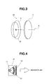
- FIG. 3 is a perspective view showing components of a light-emitting device according to a second embodiment of the invention.
- the light-emitting device of the invention is depicted at 20 in FIG. 3 as comprising an LED light source 1A capable of emitting pseudo-white light containing a blue light component and the inventive wavelength conversion member 3 disposed on the optical axis A of the light source 1A.
- the LED light source 1A used herein is a light source of pseudo-white light emission, for example, comprising a blue LED chip capable of emitting blue light of wavelength 420 to 490 nm, preferably 440 to 470 nm, which is surface coated with a resin coating containing a yellow or green phosphor.
- the wavelength conversion member 3 and reflector 5 are the same as in the first embodiment.
- the light-emitting device 20 of the above-mentioned construction operates such that once the LED light source 1A emits pseudo-white light, the pseudo-white light enters the wavelength conversion member 3 where a portion of blue light in pseudo-white light is absorbed by the red phosphor therein and converted to red light. As a result, white light having high color rendering is obtained.
- the light-emitting device 20 of the invention is constructed such that the phosphor in the wavelength conversion member 3 is excited by a portion of pseudo-white light from the LED light source 1A serving as excitation light, uniform light of consistent chromaticity is produced without a difference in emission color which is found in a light-emitting device comprising a plurality of LED light sources, due to variations of LED outputs.
- the light-emitting device 20 of the invention offers a high freedom to the step of toning the color of light emission via simple adjustment because the wavelength conversion member 3 for red wavelength is independent of the wavelength conversion section of the LED light source 1A and because the wavelength conversion member 3 whose phosphor content has been adjusted in proportion to light emission of the desired chromaticity may be mounted at the last stage of assembly of the light-emitting device 20. Further, since the wavelength conversion member 3 is spatially independent from the LED light source (light-emitting chips), it is unlikely that the member 3 is heated at high temperature, resulting in the phosphor therein keeping stable properties and a long lifetime.
- the arrangement of components may be changed as long as the spirit of the invention is not altered, and the invention is not limited to the embodiments illustrated above.
- the LED light source 1A is a blue LED
- the blue LED once the blue LED emits blue light, the blue light enters the wavelength conversion member 3 where a portion of blue light is converted into red light by the red phosphor therein whereupon a mixture of blue light and red light emerges.
- the light-emitting device of the invention is suited as a light-emitting device of remote phosphor type wherein a wavelength conversion member is spaced apart from a blue LED light source by a gas or vacuum layer. Because of its light distribution characteristics distinguishable from general LED light-emitting devices, such as surface emission and a wide radiation angle, the remote phosphor system is best suited as illuminators for providing illumination over a wide area.
- Transparent polypropylene pellets were dried at 90°C for 3 hours.
- K 2 (Si 0.97 Mn 0.03 )F 6 phosphor having a particle size D50 of 17.6 ⁇ m was incorporated into 4.5 kg of the polypropylene pellets having additives admixed therein, yielding the polypropylene pellets loaded with 10 wt% of K 2 (Si 0.97 Mn 0.03 )F 6 .
- K 2 (Si 0.87 Mn 0.03 )F 6 -loaded polypropylene pellets having a K 2 (Si 0.97 Mn 0.03 )F 6 content of 1 to 33 wt% were obtained.
- the K 2 (Si 0.97 Mn 0.03 )F 6 -loaded polypropylene pellets were molded into a plate-shaped member having a thickness of 2 mm and a diameter of 20 mm.
- the plate-shaped wavelength conversion member was evaluated for a transmittance of excitation light and an external quantum efficiency of red emission resulting from wavelength conversion of excitation light. Further, the light emission from the member upon irradiation of blue light was visually observed on the back side to examine whether or not the emission was uniform. The results of evaluation are shown in Table 1.
- Example 1-1 having a low phosphor content, most light is transmitted, and light emission from the wavelength conversion member is very slight, and that as the content of red phosphor increases, the transmittance of excitation light is reduced and red light emission becomes more intense.
- the light emission from the member upon irradiation of blue light was visually observed on the back side to examine the variation of limit emission, no variations were seen.
- Example 1 In Comparative Example 1, intense red light emission was observed, but contained variations including bright and dark spots. [Table 1] Red phosphor content (wt%) Transmittance of excitation light (%) External quantum efficiency of red light Variation of light emission (as visually observed) Example 1-1 1 98.7 - none Example 1-2 3 63.1 0.295 none Example 1-3 5 55.4 0.366 none Example 1-4 10 35.8 0.520 none Comparative Example 1 33 5.4 0.710 observed
- Example 2 plate-shaped wavelength conversion members having a red phosphor content of 5 wt% and 10 wt% were prepared. Also, a similar wavelength conversion member containing 5 wt% of YAG:Ce 3+ phosphor was prepared. By combining these members, a light-emitting device of the structure shown in FIG. 4 was manufactured. Depicted in FIG. 4 are a blue LED light source 11, a yellow wavelength conversion member 12, a red wavelength conversion member 13, and a package 16. As the excitation light, a blue light source having a 2-W blue LED chip of 450 nm light emission (Cree, Inc.) was used. The combination of wavelength conversion members for each light-emitting device is shown in Table 2.
- Light-emitting devices were manufactured under the following conditions.
- K 2 (Si 0.97 Mn 0.03 )F 6 phosphor used in Example 1 was mixed with transparent polypropylene pellets, obtaining polypropylene pellets having a K 2 (Si 0.97 Mn 0.03 )F 6 phosphor concentration of 2.5 wt% and 10 wt%.
- the K 2 (Si 0.97 Mn 0.03 )F 6 -loaded polypropylene pellets were molded into a plate-shaped red wavelength conversion member of 2 mm thick and 100 mm squares.
- pellets were prepared by incorporating 2.5 wt%, 3.0 wt%, 4.0 wt% or 5.0 wt% of Y 3 Al 5 O 12 :Ce powder in polycarbonate resin.
- the pellet resin was injection molded into a plate-shaped yellow wavelength conversion member of 2 mm thick and 100 mm squares.
- a white LED light-emitting device was constructed by placing two types of wavelength conversion members on an optical axis and forward of a blue LED light-emitting unit GL-RB100 (having six 2-W blue LED chips XT-E Royal Blue by Cree, Inc.) by Hino Electronic Corp.
- the combination of wavelength conversion members is shown in Table 3 such that the arrangement sequence of first and second wavelength conversion members from the LED light-emitting unit side may be one arrangement sequence of yellow wavelength conversion member and red wavelength conversion member or another arrangement sequence of red wavelength conversion member and yellow wavelength conversion member, while the combination of phosphor contents is changed.
- a device was constructed using the yellow wavelength conversion member (phosphor content 4 wt%) alone.
- the light-emitting device was measured for color temperature, average color rendering index Ra, and special color rendering index ⁇ R9 at a position spaced 20 cm from the device.
- Examples 3-1 to 3-5 using the red wavelength conversion member show a higher special color rendering index ⁇ R9 than Comparative Example 3 not using the red wavelength conversion member.
- FIG. 5 shows the emission spectrum of Example 3-2
- FIG. 6 shows the emission spectrum of Comparative Example 3.
- a comparison between FIGS. 5 and 6 reveals that the spectrum ( FIG. 5 ) of the light-emitting device using the inventive wavelength conversion member has an emission peak at wavelength of 600 nm or longer, which accounts for improvements in average color rendering index Ra and special color rendering index ⁇ R9.
- the LED light-emitting device using the inventive wavelength conversion member achieves significant improvements in average color rendering index Ra and special color rendering index ⁇ R9 over the LED light-emitting device using only the yellow wavelength conversion member. Even after the LED light-emitting device has been assembled, the chromaticity and color rendering of light emission can be adjusted by merely replacing the wavelength conversion member.
- FIG. 7 is a perspective image of such light emission.
- the yellow wavelength conversion member of Comparative Example 3 As shown in FIG. 7(B) , only the portion (right side in the figure) receiving blue light as excitation light looks bright due to light emission.
- the red wavelength conversion member of Example 3-2 as shown in FIG. 7(A) , not only the portion receiving blue light as excitation light, but also the surrounding portion (center to left side in the figure) provide light emission, indicating that the wavelength conversion member has a wide emission range.
Landscapes
- Chemical & Material Sciences (AREA)
- Engineering & Computer Science (AREA)
- Materials Engineering (AREA)
- Organic Chemistry (AREA)
- Inorganic Chemistry (AREA)
- Microelectronics & Electronic Packaging (AREA)
- Manufacturing & Machinery (AREA)
- Computer Hardware Design (AREA)
- Power Engineering (AREA)
- Led Device Packages (AREA)
- Luminescent Compositions (AREA)
- Optical Filters (AREA)
Applications Claiming Priority (2)
| Application Number | Priority Date | Filing Date | Title |
|---|---|---|---|
| JP2012287314 | 2012-12-28 | ||
| PCT/JP2013/084777 WO2014104147A1 (ja) | 2012-12-28 | 2013-12-26 | 波長変換部材及び発光装置 |
Publications (3)
| Publication Number | Publication Date |
|---|---|
| EP2940745A1 true EP2940745A1 (de) | 2015-11-04 |
| EP2940745A4 EP2940745A4 (de) | 2016-06-29 |
| EP2940745B1 EP2940745B1 (de) | 2019-08-28 |
Family
ID=51021223
Family Applications (1)
| Application Number | Title | Priority Date | Filing Date |
|---|---|---|---|
| EP13868903.9A Expired - Fee Related EP2940745B1 (de) | 2012-12-28 | 2013-12-26 | Wellenlängenumwandlungselement und lichtemittierende vorrichtung |
Country Status (7)
| Country | Link |
|---|---|
| US (1) | US9982189B2 (de) |
| EP (1) | EP2940745B1 (de) |
| JP (2) | JP5983775B2 (de) |
| KR (1) | KR102087270B1 (de) |
| CN (1) | CN104885238B (de) |
| TW (1) | TWI589674B (de) |
| WO (1) | WO2014104147A1 (de) |
Cited By (2)
| Publication number | Priority date | Publication date | Assignee | Title |
|---|---|---|---|---|
| EP3057131B1 (de) * | 2015-02-16 | 2020-06-17 | LG Innotek Co., Ltd. | Gehäuseverpackung einer lichtemittierenden vorrichtung und beleuchtungsvorrichtung damit |
| EP4083707A4 (de) * | 2019-12-26 | 2024-04-03 | Sumitomo Chemical Co | Anzeigevorrichtung |
Families Citing this family (8)
| Publication number | Priority date | Publication date | Assignee | Title |
|---|---|---|---|---|
| KR101778848B1 (ko) * | 2015-08-21 | 2017-09-14 | 엘지전자 주식회사 | 발광소자 패키지 어셈블리 및 이의 제조 방법 |
| KR102472340B1 (ko) * | 2015-08-25 | 2022-11-30 | 쑤저우 레킨 세미컨덕터 컴퍼니 리미티드 | 적색 형광체 및 이를 포함하는 발광장치 |
| US20190169496A1 (en) * | 2015-08-25 | 2019-06-06 | Lg Innotek Co., Ltd. | Red phosphor and light emitting device comprising same |
| US10113070B2 (en) * | 2015-11-04 | 2018-10-30 | Ppg Industries Ohio, Inc. | Pretreatment compositions and methods of treating a substrate |
| CN108291142B (zh) * | 2015-11-26 | 2021-03-12 | 卡任特照明解决方案有限责任公司 | 用于合成发红光磷光体的方法以及发红光磷光体 |
| JP6541638B2 (ja) * | 2016-12-28 | 2019-07-10 | 堺化学工業株式会社 | 蛍光体含有多層膜シート、並びに発光装置 |
| JP2019015848A (ja) * | 2017-07-06 | 2019-01-31 | 株式会社タムラ製作所 | 波長変換部材及びその製造方法 |
| JP7004694B2 (ja) | 2019-11-05 | 2022-01-21 | 東洋スチレン株式会社 | 良色相の成形品およびその製造方法 |
Family Cites Families (16)
| Publication number | Priority date | Publication date | Assignee | Title |
|---|---|---|---|---|
| KR101559603B1 (ko) * | 2008-02-07 | 2015-10-12 | 미쓰비시 가가꾸 가부시키가이샤 | 반도체 발광 장치, 백라이트, 컬러 화상 표시 장치, 및 그들에 사용하는 형광체 |
| JP5239043B2 (ja) | 2008-07-18 | 2013-07-17 | シャープ株式会社 | 発光装置および発光装置の製造方法 |
| JP2010023880A (ja) | 2008-07-18 | 2010-02-04 | Sharp Corp | 蛍光体混練物包装容器 |
| JP5682104B2 (ja) * | 2008-09-05 | 2015-03-11 | 三菱化学株式会社 | 蛍光体及びその製造方法と、その蛍光体を用いた蛍光体含有組成物及び発光装置、並びに、その発光装置を用いた画像表示装置及び照明装置 |
| WO2010095395A1 (ja) | 2009-02-18 | 2010-08-26 | 三井金属鉱業株式会社 | 蛍光体含有樹脂組成物及び蛍光シート |
| JP5754374B2 (ja) | 2009-03-31 | 2015-07-29 | 三菱化学株式会社 | 蛍光体、蛍光体の製造方法、蛍光体含有組成物、発光装置、照明装置及び画像表示装置 |
| JP5423120B2 (ja) * | 2009-04-17 | 2014-02-19 | 三菱化学株式会社 | 半導体発光装置 |
| JP2011029497A (ja) | 2009-07-28 | 2011-02-10 | Mitsubishi Chemicals Corp | 白色発光装置およびそれを用いた照明装置 |
| TW201140890A (en) * | 2009-12-17 | 2011-11-16 | Koninkl Philips Electronics Nv | Lighting device with light source and wavelength converting element |
| EP2540798A4 (de) | 2010-02-26 | 2014-04-30 | Mitsubishi Chem Corp | Halophosphatphosphor und weisslicht-ausgabevorrichtung |
| US20120267999A1 (en) | 2010-02-26 | 2012-10-25 | Mitsubishi Chemical Corporation | Halophosphate phosphor and white light-emitting device |
| JP5519440B2 (ja) | 2010-08-03 | 2014-06-11 | 日東電工株式会社 | 発光装置 |
| EP2629341B8 (de) * | 2010-10-15 | 2020-04-08 | Mitsubishi Chemical Corporation | Weisslichtemittierende halbleitervorrichtung und beleuchtungsvorrichtung |
| MY167700A (en) | 2011-04-08 | 2018-09-21 | Shinetsu Chemical Co | Preparation of complex fluoride and complex fluoride phosphor |
| JP2013045896A (ja) | 2011-08-24 | 2013-03-04 | Mitsubishi Chemicals Corp | 発光装置 |
| JP2012060192A (ja) | 2011-12-26 | 2012-03-22 | Toshiba Corp | 発光装置、その製造方法および発光装置製造装置 |
-
2013
- 2013-12-26 EP EP13868903.9A patent/EP2940745B1/de not_active Expired - Fee Related
- 2013-12-26 KR KR1020157020018A patent/KR102087270B1/ko active IP Right Grant
- 2013-12-26 JP JP2014554516A patent/JP5983775B2/ja not_active Expired - Fee Related
- 2013-12-26 WO PCT/JP2013/084777 patent/WO2014104147A1/ja active Application Filing
- 2013-12-26 US US14/654,901 patent/US9982189B2/en active Active
- 2013-12-26 CN CN201380068227.3A patent/CN104885238B/zh not_active Expired - Fee Related
- 2013-12-27 TW TW102148738A patent/TWI589674B/zh not_active IP Right Cessation
-
2016
- 2016-04-05 JP JP2016075852A patent/JP6197908B2/ja active Active
Cited By (2)
| Publication number | Priority date | Publication date | Assignee | Title |
|---|---|---|---|---|
| EP3057131B1 (de) * | 2015-02-16 | 2020-06-17 | LG Innotek Co., Ltd. | Gehäuseverpackung einer lichtemittierenden vorrichtung und beleuchtungsvorrichtung damit |
| EP4083707A4 (de) * | 2019-12-26 | 2024-04-03 | Sumitomo Chemical Co | Anzeigevorrichtung |
Also Published As
| Publication number | Publication date |
|---|---|
| EP2940745A4 (de) | 2016-06-29 |
| TWI589674B (zh) | 2017-07-01 |
| JP5983775B2 (ja) | 2016-09-06 |
| US20150340571A1 (en) | 2015-11-26 |
| CN104885238A (zh) | 2015-09-02 |
| KR20150099843A (ko) | 2015-09-01 |
| JP2016170419A (ja) | 2016-09-23 |
| JP6197908B2 (ja) | 2017-09-20 |
| CN104885238B (zh) | 2018-07-27 |
| TW201439278A (zh) | 2014-10-16 |
| JPWO2014104147A1 (ja) | 2017-01-12 |
| US9982189B2 (en) | 2018-05-29 |
| WO2014104147A1 (ja) | 2014-07-03 |
| KR102087270B1 (ko) | 2020-03-10 |
| EP2940745B1 (de) | 2019-08-28 |
Similar Documents
| Publication | Publication Date | Title |
|---|---|---|
| EP2940745B1 (de) | Wellenlängenumwandlungselement und lichtemittierende vorrichtung | |
| US9657221B2 (en) | Wavelength conversion member and light-emitting device | |
| US9045688B2 (en) | LED lighting arrangement including light emitting phosphor | |
| EP2940742A1 (de) | Lichtemittierende vorrichtung | |
| US10450505B2 (en) | Wavelength conversion member and light-emitting device | |
| JP6098747B2 (ja) | 調整部品及び発光装置 |
Legal Events
| Date | Code | Title | Description |
|---|---|---|---|
| PUAI | Public reference made under article 153(3) epc to a published international application that has entered the european phase |
Free format text: ORIGINAL CODE: 0009012 |
|
| 17P | Request for examination filed |
Effective date: 20150703 |
|
| AK | Designated contracting states |
Kind code of ref document: A1 Designated state(s): AL AT BE BG CH CY CZ DE DK EE ES FI FR GB GR HR HU IE IS IT LI LT LU LV MC MK MT NL NO PL PT RO RS SE SI SK SM TR |
|
| AX | Request for extension of the european patent |
Extension state: BA ME |
|
| DAX | Request for extension of the european patent (deleted) | ||
| A4 | Supplementary search report drawn up and despatched |
Effective date: 20160601 |
|
| RIC1 | Information provided on ipc code assigned before grant |
Ipc: H01L 33/50 20100101AFI20160526BHEP Ipc: C09K 11/77 20060101ALI20160526BHEP Ipc: C09K 11/67 20060101ALI20160526BHEP Ipc: C09K 11/61 20060101ALI20160526BHEP Ipc: C09K 11/02 20060101ALI20160526BHEP Ipc: C09K 11/66 20060101ALI20160526BHEP |
|
| 17Q | First examination report despatched |
Effective date: 20180620 |
|
| GRAP | Despatch of communication of intention to grant a patent |
Free format text: ORIGINAL CODE: EPIDOSNIGR1 |
|
| INTG | Intention to grant announced |
Effective date: 20190306 |
|
| GRAJ | Information related to disapproval of communication of intention to grant by the applicant or resumption of examination proceedings by the epo deleted |
Free format text: ORIGINAL CODE: EPIDOSDIGR1 |
|
| GRAR | Information related to intention to grant a patent recorded |
Free format text: ORIGINAL CODE: EPIDOSNIGR71 |
|
| GRAS | Grant fee paid |
Free format text: ORIGINAL CODE: EPIDOSNIGR3 |
|
| GRAA | (expected) grant |
Free format text: ORIGINAL CODE: 0009210 |
|
| INTC | Intention to grant announced (deleted) | ||
| RBV | Designated contracting states (corrected) |
Designated state(s): DE NL |
|
| AK | Designated contracting states |
Kind code of ref document: B1 Designated state(s): DE NL |
|
| INTG | Intention to grant announced |
Effective date: 20190723 |
|
| REG | Reference to a national code |
Ref country code: DE Ref legal event code: R096 Ref document number: 602013059871 Country of ref document: DE |
|
| REG | Reference to a national code |
Ref country code: NL Ref legal event code: FP |
|
| PGFP | Annual fee paid to national office [announced via postgrant information from national office to epo] |
Ref country code: DE Payment date: 20191210 Year of fee payment: 7 Ref country code: NL Payment date: 20191114 Year of fee payment: 7 |
|
| REG | Reference to a national code |
Ref country code: DE Ref legal event code: R097 Ref document number: 602013059871 Country of ref document: DE |
|
| PLBE | No opposition filed within time limit |
Free format text: ORIGINAL CODE: 0009261 |
|
| STAA | Information on the status of an ep patent application or granted ep patent |
Free format text: STATUS: NO OPPOSITION FILED WITHIN TIME LIMIT |
|
| 26N | No opposition filed |
Effective date: 20200603 |
|
| REG | Reference to a national code |
Ref country code: DE Ref legal event code: R119 Ref document number: 602013059871 Country of ref document: DE |
|
| REG | Reference to a national code |
Ref country code: NL Ref legal event code: MM Effective date: 20210101 |
|
| PG25 | Lapsed in a contracting state [announced via postgrant information from national office to epo] |
Ref country code: NL Free format text: LAPSE BECAUSE OF NON-PAYMENT OF DUE FEES Effective date: 20210101 |
|
| PG25 | Lapsed in a contracting state [announced via postgrant information from national office to epo] |
Ref country code: DE Free format text: LAPSE BECAUSE OF NON-PAYMENT OF DUE FEES Effective date: 20210701 |