WO2014104147A1 - Wavelength conversion member and light-emitting device - Google Patents
Wavelength conversion member and light-emitting device Download PDFInfo
- Publication number
- WO2014104147A1 WO2014104147A1 PCT/JP2013/084777 JP2013084777W WO2014104147A1 WO 2014104147 A1 WO2014104147 A1 WO 2014104147A1 JP 2013084777 W JP2013084777 W JP 2013084777W WO 2014104147 A1 WO2014104147 A1 WO 2014104147A1
- Authority
- WO
- WIPO (PCT)
- Prior art keywords
- wavelength conversion
- light
- conversion member
- phosphor
- resin
- Prior art date
Links
- 0 CCC(C)CCCC1*CCC1 Chemical compound CCC(C)CCCC1*CCC1 0.000 description 2
Images

Classifications
-
- C—CHEMISTRY; METALLURGY
- C09—DYES; PAINTS; POLISHES; NATURAL RESINS; ADHESIVES; COMPOSITIONS NOT OTHERWISE PROVIDED FOR; APPLICATIONS OF MATERIALS NOT OTHERWISE PROVIDED FOR
- C09K—MATERIALS FOR MISCELLANEOUS APPLICATIONS, NOT PROVIDED FOR ELSEWHERE
- C09K11/00—Luminescent, e.g. electroluminescent, chemiluminescent materials
- C09K11/08—Luminescent, e.g. electroluminescent, chemiluminescent materials containing inorganic luminescent materials
- C09K11/61—Luminescent, e.g. electroluminescent, chemiluminescent materials containing inorganic luminescent materials containing fluorine, chlorine, bromine, iodine or unspecified halogen elements
- C09K11/615—Halogenides
- C09K11/616—Halogenides with alkali or alkaline earth metals
-
- C—CHEMISTRY; METALLURGY
- C09—DYES; PAINTS; POLISHES; NATURAL RESINS; ADHESIVES; COMPOSITIONS NOT OTHERWISE PROVIDED FOR; APPLICATIONS OF MATERIALS NOT OTHERWISE PROVIDED FOR
- C09K—MATERIALS FOR MISCELLANEOUS APPLICATIONS, NOT PROVIDED FOR ELSEWHERE
- C09K11/00—Luminescent, e.g. electroluminescent, chemiluminescent materials
- C09K11/02—Use of particular materials as binders, particle coatings or suspension media therefor
-
- C—CHEMISTRY; METALLURGY
- C09—DYES; PAINTS; POLISHES; NATURAL RESINS; ADHESIVES; COMPOSITIONS NOT OTHERWISE PROVIDED FOR; APPLICATIONS OF MATERIALS NOT OTHERWISE PROVIDED FOR
- C09K—MATERIALS FOR MISCELLANEOUS APPLICATIONS, NOT PROVIDED FOR ELSEWHERE
- C09K11/00—Luminescent, e.g. electroluminescent, chemiluminescent materials
- C09K11/08—Luminescent, e.g. electroluminescent, chemiluminescent materials containing inorganic luminescent materials
- C09K11/61—Luminescent, e.g. electroluminescent, chemiluminescent materials containing inorganic luminescent materials containing fluorine, chlorine, bromine, iodine or unspecified halogen elements
- C09K11/617—Silicates
-
- C—CHEMISTRY; METALLURGY
- C09—DYES; PAINTS; POLISHES; NATURAL RESINS; ADHESIVES; COMPOSITIONS NOT OTHERWISE PROVIDED FOR; APPLICATIONS OF MATERIALS NOT OTHERWISE PROVIDED FOR
- C09K—MATERIALS FOR MISCELLANEOUS APPLICATIONS, NOT PROVIDED FOR ELSEWHERE
- C09K11/00—Luminescent, e.g. electroluminescent, chemiluminescent materials
- C09K11/08—Luminescent, e.g. electroluminescent, chemiluminescent materials containing inorganic luminescent materials
- C09K11/77—Luminescent, e.g. electroluminescent, chemiluminescent materials containing inorganic luminescent materials containing rare earth metals
- C09K11/7766—Luminescent, e.g. electroluminescent, chemiluminescent materials containing inorganic luminescent materials containing rare earth metals containing two or more rare earth metals
- C09K11/7774—Aluminates
-
- H—ELECTRICITY
- H01—ELECTRIC ELEMENTS
- H01L—SEMICONDUCTOR DEVICES NOT COVERED BY CLASS H10
- H01L33/00—Semiconductor devices with at least one potential-jump barrier or surface barrier specially adapted for light emission; Processes or apparatus specially adapted for the manufacture or treatment thereof or of parts thereof; Details thereof
- H01L33/48—Semiconductor devices with at least one potential-jump barrier or surface barrier specially adapted for light emission; Processes or apparatus specially adapted for the manufacture or treatment thereof or of parts thereof; Details thereof characterised by the semiconductor body packages
- H01L33/50—Wavelength conversion elements
- H01L33/501—Wavelength conversion elements characterised by the materials, e.g. binder
- H01L33/502—Wavelength conversion materials
-
- H—ELECTRICITY
- H01—ELECTRIC ELEMENTS
- H01L—SEMICONDUCTOR DEVICES NOT COVERED BY CLASS H10
- H01L33/00—Semiconductor devices with at least one potential-jump barrier or surface barrier specially adapted for light emission; Processes or apparatus specially adapted for the manufacture or treatment thereof or of parts thereof; Details thereof
- H01L33/48—Semiconductor devices with at least one potential-jump barrier or surface barrier specially adapted for light emission; Processes or apparatus specially adapted for the manufacture or treatment thereof or of parts thereof; Details thereof characterised by the semiconductor body packages
- H01L33/50—Wavelength conversion elements
- H01L33/507—Wavelength conversion elements the elements being in intimate contact with parts other than the semiconductor body or integrated with parts other than the semiconductor body
Definitions
- the present invention uses a wavelength conversion member used for improving the chromaticity of illumination light of a light emitting device such as a general illumination using a blue light emitting diode (LED), a backlight light source, a headlight light source, and the wavelength conversion member.
- a light emitting device such as a general illumination using a blue light emitting diode (LED), a backlight light source, a headlight light source, and the wavelength conversion member.
- the present invention relates to a light emitting device.
- the light-emitting diode is one of the most efficient light sources currently available.
- white light-emitting diodes are rapidly expanding in the market as next-generation light sources that replace incandescent bulbs, fluorescent lamps, CCFL (Cold Cathode Fluorescent Lamp) backlights, halogen lamps, and the like.
- a white LED Light Emitting Diode
- a white LED that combines a blue light emitting diode (blue LED) and a phosphor that emits light having a longer wavelength, for example, yellow or green, by blue light excitation. Lighting
- the white LED has a structure in which a phosphor is arranged on a blue LED or in the very vicinity thereof mixed with resin or glass, and a part or all of the blue light is integrated with the blue LED.
- the so-called white LED device in which pseudo white light is obtained by wavelength conversion with the phosphor layer, is the mainstream.
- a light-emitting device that employs a method in which the phosphor is arranged at a distance of several mm to several tens of mm from the blue LED, and part or all of the blue light is wavelength-converted by the phosphor.
- the distance from the LED is effective for improving the efficiency of the light emitting device and suppressing fluctuations in color tone.
- a member in which the wavelength conversion member including the phosphor is arranged apart from the LED light source in this way is called a remote phosphor, and such a light emission method is called a “remote phosphor method”.
- Such a remote phosphor light-emitting method has an advantage of improving overall color unevenness when used as illumination, and has recently been studied rapidly.
- a remote phosphor type light emitting device for example, wavelength conversion made of resin or glass in which yellow phosphor particles, green phosphor particles, and further red phosphor particles are dispersed as a remote phosphor on the front surface of a blue LED.
- a light emitting device that obtains white light by arranging members is generally used.
- Y 3 Al 5 O 12 Ce, (Y, Gd) 3 (Al, Ga) 5 O 12 : Ce, (Y, Gd) 3 Al 5 O 12 : Ce,
- Tb 3 Al 5 O 12 Ce, (Sr, Ca, Ba) 2 SiO 4 : Eu, ⁇ -SiAlON: Eu, etc.
- phosphors suitable for the LED lighting apparatus there are many examples of phosphors that emit green light or yellow light, but as phosphors emitting red light, nitride phosphors called CASN and S-CASN are used. There are not many known oxynitride phosphors called ⁇ -SIALON phosphors. In addition, since these phosphors emitting red light usually require synthesis at high temperature and high pressure, special equipment that can withstand high temperature and high pressure is required for mass synthesis.
- M is one or more tetravalent elements selected from Si, Ti, Zr, Hf, Ge and Sn
- A is selected from Li, Na, K, Rb and Cs, and at least Na and And / or one or more alkali metals containing K, and x is 0.001 to 0.3.
- Patent Document 1 Japanese Patent Laid-Open No. 2012-224536
- the phosphor can be synthesized at a low temperature of 100 ° C. or lower and normal pressure, and a phosphor having a good particle size and quantum efficiency can be obtained. There was a problem in durability under high humidity.
- the present invention has been made in view of the above circumstances, and an object thereof is to provide a wavelength conversion member using a red phosphor suitable for an LED and a light emitting device using the wavelength conversion member.
- the present inventors focused on a resin phosphor plate in which a phosphor is mixed with a thermoplastic resin as a new wavelength conversion member, and studied a mixing method, a mixing amount, a thickness of the phosphor plate, and an arrangement in the LED device. At that time, in order to improve the color reproducibility of the LED device, a manganese-activated bifluoride phosphor was examined as a red phosphor capable of complementing the light emission characteristics of the yellow phosphor in the pseudo white LED device.
- the inventors have been able to improve the moisture resistance by the wavelength conversion member of the resin molded body in which the red phosphor made of manganese-activated bifluoride is dispersed in a specific thermoplastic resin.
- a red phosphor made of manganese-activated bifluoride is specified. It is found that the color reproducibility of the LED device can be improved by arranging the wavelength conversion member of the resin molding dispersed in the thermoplastic resin in front of or behind the yellow or green wavelength conversion member. It came to be accomplished.
- the present invention provides the following wavelength conversion member and light emitting device.
- M is one or more tetravalent elements selected from Si, Ti, Zr, Hf, Ge and Sn
- A is selected from Li, Na, K, Rb and Cs, and at least Na and And / or one or more alkali metals containing K, and x is 0.001 to 0.3.
- a wavelength conversion member comprising a resin molding made of one or more thermoplastic resins selected from the group consisting of resin, acrylic resin, nylon, polyester resin, polycarbonate resin, vinyl chloride resin
- the double fluoride phosphors, K 2 (Si 1-x Mn x) F 6 (x is as defined above) is manganese activated potassium hexafluorosilicate represented by [1] wavelength conversion member according. [3] The wavelength conversion member according to [1] or [2], wherein the thermoplastic resin contains polypropylene and / or polystyrene. [4] The wavelength conversion member according to [1] or [2], wherein the thermoplastic resin contains 40% by mass or more of polypropylene and / or polystyrene.
- the blue LED light source or pseudo white LED light source that emits light containing a blue light component having a wavelength of 420 to 490 nm, and any one of [1] to [4] disposed on the optical axis of the LED light source A wavelength conversion member.
- the wavelength conversion member of the present invention it is possible to provide a novel wavelength conversion member in which a predetermined amount of manganese-activated bifluoride particles is uniformly kneaded into a thermoplastic resin and molded.
- a light emitting device illumination device
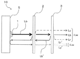
- FIG. 2 is a schematic cross-sectional view illustrating a state of wavelength conversion of light in the light emitting device of FIG. 1. It is a schematic perspective view which shows the structure of 2nd Embodiment of the light-emitting device which concerns on this invention.
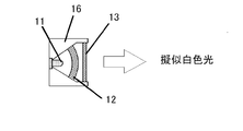
- 6 is a schematic cross-sectional view showing a configuration of a pseudo white LED light-emitting device for evaluation of Example 2.
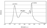
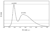
- FIG. It is a figure which shows the emission spectrum of the light-emitting device of Example 3-2. It is a figure which shows the emission spectrum of the light-emitting device of the comparative example 3.
- 10 is a perspective image of light emission states of wavelength conversion members of Example 3-2 and Comparative Example 3.
- the wavelength conversion member according to the present invention is a polyolefin, polystyrene, styrene copolymer, fluororesin, acrylic resin, nylon, polyester resin, polycarbonate in which a predetermined double fluoride phosphor is dispersed in a content of 30% by mass or less. It is a resin molding of one or more thermoplastic resins selected from the group of resins, vinyl chloride resins and polyether resins.
- the double fluoride phosphor used in the present invention has the following formula (1): A 2 (M 1-x Mn x ) F 6 (1) Wherein M is one or more tetravalent elements selected from Si, Ti, Zr, Hf, Ge and Sn, A is selected from Li, Na, K, Rb and Cs, and at least Na and And / or one or more alkali metals containing K, and x is 0.001 to 0.3, preferably 0.001 to 0.1.) It is a red phosphor represented by
- This phosphor is a manganese-activated bifluoride phosphor having a structure in which a part of the constituent elements of the double fluoride represented by A 2 MF 6 is substituted with manganese.
- the activator manganese is not particularly limited, but is obtained by substituting manganese for the tetravalent element site represented by A 2 MF 6, that is, a tetravalent element. Those substituted as manganese (Mn 4+ ) are preferred. In this case, it may be expressed as A 2 MF 6 : Mn 4+ .
- the double fluoride phosphor is particularly preferably manganese-activated potassium silicofluoride represented by K 2 (Si 1-x Mn x ) F 6 (x is the same as above).
- Such a manganese-activated bifluoride phosphor is excited by blue light having a wavelength of 420 to 490 nm, preferably 440 to 470 nm, and has a light emission peak or a maximum light emission peak within a wavelength range of 600 to 660 nm. To emit.
- the double fluoride phosphor represented by the above formula (1) may be produced by a conventionally known method.
- a metal fluoride raw material is dissolved or dispersed in hydrofluoric acid and heated to evaporate. It is good to use what was obtained by making it dry.
- the particle size D50 of 50% cumulative volume in the particle size distribution is 2 ⁇ m or more and 200 ⁇ m or less, preferably 10 ⁇ m or more and 60 ⁇ m or less.
- the D50 value is less than 2 ⁇ m, the light emission efficiency as a phosphor is lowered.
- the phosphor particles are large, there is essentially no problem with light emission.
- defects such as non-uniform distribution of the phosphor are likely to occur. The following are easy to use.
- the particle size measurement method in the present invention is, for example, a dry laser diffraction scattering method in which the target powder is sprayed in the air or dispersed and suspended, and laser light is irradiated to obtain the particle size from the diffraction pattern. It is preferable because it is not affected by humidity and can evaluate particle size distribution.
- the content of the manganese-activated bifluoride phosphor in the wavelength conversion member of the present invention varies depending on the thickness of the conversion member and the target color reproducibility, but is preferably 0.1% by mass or more, more preferably 2% by mass. Or more, more preferably 3% by mass or more, particularly preferably 5% by mass or more, and 30% by mass or less, preferably 15% by mass or less, more preferably 12% by mass or less, and further preferably 10% by mass or less. .
- the phosphor content exceeds 30% by mass, friction and wear between the fluorescent powder during kneading and the kneading screw of the molding machine increase. As a result, in the resin-encapsulated phosphor (wavelength conversion member) Discoloration will occur.
- the content is excessively high, the fluorescent powder partially aggregates in the sealing resin, and the light emission distribution in the resin-encapsulated fluorescent material becomes non-uniform.
- the content is less than 2% by mass, the light emission amount of red light is small and the effect of improving the color rendering properties may be lowered.
- the content is desirably 2% by mass or more.
- thermoplastic resin having high chemical resistance to alkali and excellent moisture resistance, and molding temperature (practical environment). We have made extensive studies on light transmission, moisture resistance, and heat resistance.
- a wavelength conversion member which is a resin-encapsulated fluorescent material, was prototyped using various thermoplastic resin materials, and the possibility of mixing manganese-activated bifluoride phosphors, optical characteristics, and moisture resistance were examined.
- a polyolefin, polystyrene or styrene copolymer, particularly polypropylene and / or polystyrene, especially polypropylene is used as the thermoplastic resin, mixing with the phosphor is possible, and the resin and the phosphor are decomposed.
- the knowledge that there was little deterioration was acquired.
- investigations were also made on fluororesin, acrylic resin, nylon (polyamide resin), polyester resin, polycarbonate resin, vinyl chloride resin, and polyether resin, and it was confirmed that they could be used as wavelength conversion members.
- thermoplastic resin used in the present invention polyolefins such as polyethylene and polypropylene, polystyrenes such as general-purpose polystyrene (GPPS), styrene / maleic acid copolymer, styrene / methyl methacrylate copolymer, Examples include styrene copolymers such as acrylonitrile / butadiene / styrene copolymer (ABS), and other examples include fluororesin, acrylic resin, nylon, polyester resin, polycarbonate resin, vinyl chloride resin, and polyether resin. 1 type (s) or 2 or more types selected from among them are used.
- GPPS general-purpose polystyrene
- ABS acrylonitrile / butadiene / styrene copolymer
- fluororesin acrylic resin, nylon, polyester resin, polycarbonate resin, vinyl chloride resin, and polyether resin. 1 type (s) or 2 or more types selected from among them are
- the thermoplastic resin used by this invention is a thermoplastic resin containing 40 mass% or more of polypropylene and / or polystyrene, especially polypropylene.
- the polypropylene may be any of a homopolymer, a block copolymer, and a random copolymer, but the copolymer is preferably a copolymer with ethylene.
- a random copolymer type ethylene copolymer containing a small amount of 2% to 6% by mass in the copolymer is preferable, and a melt flow rate (MFR) defined by JIS K 7210 is about 5 to 30 g / 10 min. Those that can be injection molded are more preferred.
- the molding method is not particularly limited, but injection molding that can be molded in a short time is more preferable.
- the wavelength conversion member of the present invention as in the case of the conventional thermoplastic material, 0.1 to 0 using an antioxidant, a light stabilizer, a stabilizer including an ultraviolet absorber and a molding lubricant as an auxiliary agent. It can mix
- a heavy metal deactivator may be added with a maximum of 0.3% by mass as a guide.
- a light diffusing agent is mixed as an aid for improving the diffusibility of light passing through the member.
- the light diffusing agent include inorganic ceramic powders such as talc, aluminum oxide, silicon oxide, aluminum silicate, and yttrium oxide. Among them, aluminum oxide powder or silicon oxide having high transparency and low loss of transmitted light. Powder is preferred.
- the particle size D50 value of the light diffusing agent is preferably 0.1 ⁇ m or more and 20 ⁇ m or less.
- the efficacy as a light diffusing agent may be lowered.
- the blending amount of the light diffusing agent is preferably 0.05 to 5% by mass, more preferably 0.05 to 1.5% by mass, and still more preferably 0.1 to 0.5% by mass. If the blending amount is less than 0.05% by mass, the light diffusion effect may not be sufficient, and if it exceeds 5% by mass, the light transmittance of the wavelength conversion member may be lowered.
- the above thermoplastic resin, manganese-activated bifluoride phosphor, and other auxiliaries are used as raw materials, mixed in a mixer, and made into an arbitrary shape according to the application.
- Thermoforming For example, it may be molded into a target shape suitable for the wavelength conversion member of the light emitting device at the time of mixing, or once molded into a pellet shape, when necessary, the wavelength conversion of the target shape from this pellet shape You may shape
- the average thickness of the wavelength conversion member corresponds to the required wavelength conversion performance (the amount of light in the red wavelength region that is absorbed and emitted with respect to the amount of incident blue excitation light, the transmittance of blue excitation light, etc.). Thus, it is determined from the relationship with the content of the manganese activated double fluoride phosphor, and for example, 0.5 to 5 mm is preferable.
- the wavelength conversion member thus obtained becomes a resin molded body in which a manganese-activated bifluoride phosphor is sealed with a predetermined thermoplastic resin, and the moisture resistance is remarkably improved. Further, the wavelength converting member optically emits fluorescence in the red wavelength region of about 600 to 660 nm when excited with blue light having a wavelength of 420 to 490 nm. Therefore, the wavelength converting member of the present invention containing a predetermined manganese-activated bifluoride Is applied to the light emitting device, a red wavelength component can be easily added to the emission spectrum, and the color rendering properties of the light emitting device, in particular, the average color rendering index Ra and the special color rendering index ⁇ R9 can be expected.
- the manganese-activated bifluoride phosphor has a relatively small absorption coefficient for blue light having a wavelength of 420 to 490 nm, and therefore has a characteristic that blue light is likely to enter the inside of the wavelength conversion member. Yes. For this reason, only the portion where the blue light is incident does not emit light in the wavelength conversion member, but the entire wavelength conversion member emits light, that is, a light emission source in a wide range according to the shape and size of the wavelength conversion member. In particular, it is suitable for a surface emitting light emitting device.
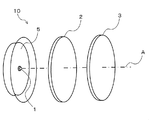
- FIG. 1 is a perspective view showing a configuration of a light emitting device according to a first embodiment of the present invention.
- a light emitting device 10 according to the present invention includes an LED light source 1 that emits blue light, and the above-described multifluoride phosphor that is disposed on the optical axis A of the LED light source 1.
- System wavelength conversion member, green wavelength conversion member, etc. 2.
- the LED light source 1 needs to contain the emitted light which can excite the fluorescent substance contained in all the wavelength conversion members 2 and 3 arrange
- the LED light source 1 is preferably composed of a plurality of LED chips for LED illumination.
- the chromaticity of the emitted light of the light emitting device 10 can be adjusted by the thicknesses of the wavelength conversion members 2 and 3, the phosphor content, the arrangement of the LED light source 1 on the optical axis, and the like.
- the wavelength conversion member 3 of the present invention is arranged in this order, One mode for obtaining white light with high color rendering properties will be described.
- the other wavelength conversion member 2 is a resin molding in which a yellow phosphor or a green phosphor is dispersed.
- a yellow or green wavelength conversion member in which a phosphor such as SiAlON: Eu 2+ is kneaded into a thermoplastic resin is preferable.
- the phosphor content in the other wavelength conversion member 2 is determined in consideration of the amount of incident blue light, the amount of light emitted in the yellow wavelength region, the transmittance of blue light, and the like.
- Y 3 Al 5 O 12 In the case of a 2 mm-thick plate material kneaded with Ce 3+ phosphor, the kneading concentration is preferably 0.2 to 5% by mass, and more preferably 1 to 4% by mass.
- the wavelength conversion member 3 is the wavelength conversion member of the present invention described above, and has a shape in which light from the LED light source 1 and the wavelength conversion member 2 is incident and light is efficiently emitted as a light emitting device. These wavelength conversion members 2 and 3 are preferably independent members that can be handled independently in the light emitting device 10.
- the shape of the wavelength conversion members 2 and 3 is not limited to the disk shape shown in FIG. 1, and may be a curved surface such as an incandescent light bulb or other shapes.
- the wavelength conversion member 3 has an excitation light transmittance of a wavelength of 420 to 490 nm of preferably 20% or more and 90% or less, and more preferably 30% or more and 70% or less. If the excitation light transmittance is less than 20%, the blue light emitted from the light emitting device may be insufficient, and the color balance may be deteriorated. If it exceeds 90%, the red light may be insufficient, and the effect of improving the color rendering property may not be expected. is there.
- the distance between the wavelength conversion member 3 and the LED light source 1 is preferably 2 to 100 mm, more preferably 5 to 10 mm. Although it can be used even when the above range is exceeded, if the distance is less than 2 mm, the wavelength conversion member may be deteriorated due to the heat effect from the LED light source 1, and if it exceeds 100 mm, the wavelength conversion member may be too large. is there.
- the blue light Lb when the blue light Lb is emitted from the LED light source 1, the blue light Lb first enters the other wavelength conversion member 2, and a part of the blue light Lb is generated.
- the yellow light Ly and the remaining blue light Lb are incident on the wavelength conversion member 3, and a part of the remaining blue light Lb is absorbed by the red phosphor included in the wavelength conversion member 3, and includes light including a red wavelength region (
- the light is converted into Lr (referred to herein as red light) and emitted together with the yellow light Ly that has passed through the wavelength conversion member 3 and the remaining blue light Lb.
- red light referred to herein as red light
- both phosphors in the wavelength conversion members 2 and 3 are configured to sequentially excite excitation light from the same LED light source 1, so that a plurality of white LED light sources are used. There is no difference in emission color due to variations in LED output as in the light emitting device based, and chromaticity is stable and uniform light emission is obtained. Further, according to the light emitting device 10 of the present invention, the wavelength conversion members 2 and 3 having the phosphor content adjusted in correspondence with the light emission of the target chromaticity at the final stage of the assembly of the light emitting device 10 are provided. Assembling is possible, and light emission toning with a high degree of freedom is possible by simple adjustment.
- the wavelength conversion member 3 of the present invention transmits most of light in the yellow wavelength region (or green wavelength region), the light control of the light emitting device 10 is easy. Further, since the wavelength conversion members 2 and 3 are spatially independent from the LED light source (light emitting chip) 1, the wavelength conversion members 2 and 3 are unlikely to become high temperature, and the characteristics of the contained phosphor are stable and long. Life is reached.
- the arrangement order of the wavelength conversion members 2 and 3 on the optical axis of the LED light source 1 may be changed, and the wavelength conversion member 3 of the present invention and the other wavelength conversion member 2 may be arranged in this order from the LED light source 1 side. .
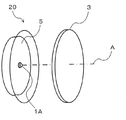
- FIG. 3 is a perspective view showing the configuration of the light emitting device according to the second embodiment of the present invention.
- the light emitting device 20 according to the present invention is disposed on the LED light source 1A that emits pseudo white light including a blue wavelength component and the optical axis A of the LED light source 1A.
- the wavelength conversion member 3 is provided.
- the LED light source 1A emits pseudo white light in which a blue LED surface emitting blue light having a wavelength of 420 to 490 nm, preferably 440 to 470 nm, is coated with a resin paint containing a yellow phosphor or a green phosphor. Light source.
- the wavelength conversion member 3 and the reflection plate 5 are the same as those in the first embodiment.
- the pseudo white light when the pseudo white light is emitted from the LED light source 1A, the pseudo white light is incident on the wavelength conversion member 3, and part of the blue light in the pseudo white light is included in the wavelength conversion member 3. It is converted into red light by the red phosphor. As a result, white light with high color rendering properties can be obtained.
- a part of the pseudo white light from the LED light source 1A is configured to excite the phosphor in the wavelength conversion member 3 as excitation light, and thus is based on a plurality of LED light sources.
- the wavelength converting member 3 for red wavelength is independent from the wavelength converting portion of the LED light source 1A.
- the wavelength conversion member 3 having a predetermined phosphor content may be assembled in correspondence with light emission of chromaticity, and light emission toning with a high degree of freedom is possible with simple adjustment.
- the wavelength conversion member 3 is spatially independent from and separated from the LED light source (light emitting chip) 1A, the wavelength conversion member 3 is unlikely to become high temperature, the characteristics of the contained phosphor are stable, and the life is long. It becomes.
- each component can be changed without changing the gist of the present invention, and the present invention is not limited to the embodiment described above.
- the LED light source 1A shown in FIG. 3 is a blue LED
- the blue light is incident on the wavelength conversion member 3, and a part of the blue light is included in the wavelength conversion member 3.
- the red phosphor is converted into red light, and light in which blue light and red light are mixed is emitted.
- the light emitting device of the present invention is suitable as a remote phosphor type light emitting device in which a wavelength conversion member is disposed at a location away from a blue LED light source via a gas layer or a vacuum layer.
- the remote phosphor has a light distribution characteristic different from that of a general LED light-emitting device, such as a surface emission and a large emission angle, and is particularly suitable for a lighting fixture that illuminates a wide area.
- Example 1 After the transparent polypropylene pellets were dried at 90 ° C. for 3 hours, stearyl- ⁇ - (3,5-t-butyl-4-hydroxyphenyl) propionate, cyclic neopentanetetraylbis (2,6- Di-t-butyl-4-methylphenyl) phosphite, bis (2,2,6,6-tetramethyl-4-piperidyl) sebacate, 2- (2′-hydroxy-3′-tert-butyl-5 ′) -Methylphenyl) -5-chlorobenzotriazole and calcium stearate added to 0.1% by weight, 0.1% by weight, 0.3% by weight, 0.1% by weight and 0.05% by weight, respectively And mixed with stirring.
- the obtained K 2 (Si 0.97 Mn 0.03 ) F 6 -containing polypropylene pellets were molded into a plate-like member having a thickness of 2 mm and a diameter of 20 mm by a 20 t horizontal injection molding machine.
- the quantum efficiency measurement system QE1100 (manufactured by Otsuka Electronics Co., Ltd.) evaluates the transmittance of the excitation light and the external quantum efficiency of red light emission obtained by converting the wavelength of the excitation light. Went. Furthermore, the presence or absence of light emission unevenness when irradiated with blue light was visually observed from the back side. The above evaluation results are shown in Table 1.
- Example 1-1 the phosphor content in Example 1-1 was low, so that most of the light was transmitted and the light emitted from the wavelength conversion member was negligible. As the content of the red phosphor increased, the transmittance of the excitation light decreased and the red light emission became stronger. Moreover, although the presence or absence of the light emission nonuniformity by irradiating blue light was observed visually from the back side, the light emission nonuniformity was not recognized. In Comparative Example 1, strong red light emission was observed, but light emission unevenness was observed in the light and dark parts.
- Example 2 A plate-like wavelength conversion member having a red phosphor content of 5% by mass and 10% by mass was produced in the same manner as in Example 1. Moreover, the same wavelength conversion member containing 5 mass% of YAG: Ce3 + fluorescent substance was produced, and the light-emitting device of the structure shown in FIG. 4 was produced combining these.
- 11 is a blue LED light source
- 12 is a yellow wavelength conversion member
- 13 is a red wavelength conversion member
- 16 is a package.
- a blue light source using a 2W blue LED chip manufactured by Cree that emits 450 nm light was used as the excitation light. Table 2 shows combinations of wavelength conversion members of the respective light emitting devices.
- the color temperature, average color rendering index Ra, and special color rendering index ⁇ R9 for each light emitting device were measured using a spectral irradiance meter CL-500A (manufactured by Konica Minolta Optics). For comparison, a light-emitting device that does not use the red wavelength conversion member was also prototyped and evaluated. The results are summarized in Table 2.
- the color temperature of the light-emitting device can be changed by adjusting the amount and thickness of the phosphor contained in the wavelength conversion member, and the average color rendering index Ra and the special color rendering index by using the red wavelength conversion member It can be seen that ⁇ R9 is improved.
- Example 3 A light emitting device was manufactured under the following conditions. Using a twin-screw extruder, the concentration of the transparent polypropylene pellets, K 2 (Si 0.97 Mn 0.03 ) used in Example 1 and mixed and the F 6 phosphor, K 2 (Si 0.97 Mn 0.03 ) F 6 phosphor Thus, a K 2 (Si 0.97 Mn 0.03 ) F 6 phosphor-containing polypropylene pellet containing 2.5% by mass and 10% by mass was obtained.
- the blue LED light emitting device (GL-RB100 (using 6 x 2W blue LED chips XT-E Royal Blue manufactured by Cree), manufactured by Hino Electronics Co., Ltd.))
- GL-RB100 using 6 x 2W blue LED chips XT-E Royal Blue manufactured by Cree), manufactured by Hino Electronics Co., Ltd.
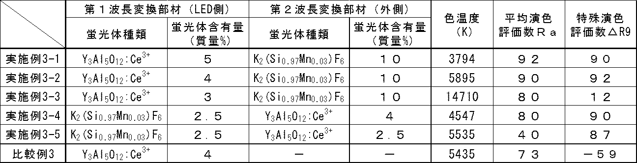
- the combination of the wavelength conversion members as shown in Table 3, the first wavelength conversion member and the second wavelength conversion member are arranged from the LED light emitting device side, and the yellow wavelength conversion member and the red wavelength conversion member are arranged in this order. What was arranged in the order of the wavelength conversion member and the yellow wavelength conversion member was produced by changing the combination of the phosphor contents, and further only the yellow wavelength conversion member (phosphor content 4 mass%) was arranged. Also made.
- the spectrum of the light emitting device using the wavelength conversion member of the present invention has an emission peak at a wavelength of 600 nm or more, which is the average color rendering index Ra.
- the special color rendering index ⁇ R9 is improved.
- the average color rendering index Ra and the special color rendering evaluation number ⁇ R9 of the LED light emitting device using only the yellow wavelength conversion member are greatly improved. be able to. Further, even after the LED light emitting device is assembled, it is possible to adjust the chromaticity and color rendering of the emitted light simply by exchanging the wavelength conversion member.
- a plate-shaped wavelength conversion member having a thickness of 2 mm and a 40 mm square was prepared for the red wavelength conversion member of Example 3-2 and the yellow wavelength conversion member of Comparative Example 3 using the pellets, and the blue LED Light from (wavelength 460 nm) was irradiated from a direction perpendicular to the 40 mm square surface of the wavelength conversion member, and the state of light emission of the wavelength conversion member viewed from the back side of the irradiation surface was visually confirmed.
- a perspective view of the light emission state is shown in FIG. In the case of the yellow wavelength conversion member of Comparative Example 3 in FIG. 7B, only the portion irradiated with the blue light that is the excitation light (the right side portion in the drawing) emits light and shines.
- the peripheral portion (from the center to the left in the figure) emits light as well as the portion irradiated with the blue light that is the excitation light. It can be seen that the light emission range of the wavelength conversion member is wide.
Abstract
Description
A2(M1-xMnx)F6 (1)
(式中、MはSi、Ti、Zr、Hf、Ge及びSnから選ばれる1種又は2種以上の4価元素、AはLi、Na、K、Rb及びCsから選ばれ、かつ少なくともNa及び/又はKを含む1種又は2種以上のアルカリ金属であり、xは0.001~0.3である。)で表されるLED用蛍光体として有望な赤色蛍光体の合成方法について検討を行なってきた(特開2012-224536号公報(特許文献1))。我々の開発した合成方法によれば、上記蛍光体の合成は、100℃以下の低温、常圧での合成ができ、粒径、量子効率の良好な蛍光体が得られるが、この蛍光体は高湿下での耐久性に課題があった。 In the past, we used the following formula (1)
A 2 (M 1-x Mn x ) F 6 (1)
Wherein M is one or more tetravalent elements selected from Si, Ti, Zr, Hf, Ge and Sn, A is selected from Li, Na, K, Rb and Cs, and at least Na and And / or one or more alkali metals containing K, and x is 0.001 to 0.3.) A method for synthesizing a promising red phosphor as an LED phosphor represented by (Japanese Patent Laid-Open No. 2012-224536 (Patent Document 1)). According to the synthesis method developed by us, the phosphor can be synthesized at a low temperature of 100 ° C. or lower and normal pressure, and a phosphor having a good particle size and quantum efficiency can be obtained. There was a problem in durability under high humidity.
〔1〕 下記式(1)
A2(M1-xMnx)F6 (1)
(式中、MはSi、Ti、Zr、Hf、Ge及びSnから選ばれる1種又は2種以上の4価元素、AはLi、Na、K、Rb及びCsから選ばれ、かつ少なくともNa及び/又はKを含む1種又は2種以上のアルカリ金属であり、xは0.001~0.3である。)
で表され、粒度分布における体積累計50%の粒径D50が2μm以上200μm以下である複フッ化物蛍光体が30質量%以下の含有量で分散された、ポリオレフィン、ポリスチレン、スチレン共重合体、フッ素樹脂、アクリル樹脂、ナイロン、ポリエステル樹脂、ポリカーボネート樹脂、塩化ビニル樹脂及びポリエーテル樹脂の群から選ばれる1種又は2種以上の熱可塑性樹脂からなる樹脂成型体であることを特徴とする波長変換部材。
〔2〕 上記複フッ化物蛍光体が、K2(Si1-xMnx)F6(xは上記と同じ)で表されるマンガン賦活ケイフッ化カリウムである〔1〕記載の波長変換部材。
〔3〕 上記熱可塑性樹脂が、ポリプロピレン及び/又はポリスチレンを含む〔1〕又は〔2〕記載の波長変換部材。
〔4〕 上記熱可塑性樹脂が、ポリプロピレン及び/又はポリスチレンを40質量%以上含む〔1〕又は〔2〕記載の波長変換部材。
〔5〕 波長420~490nmの青色光成分を含む光を出射する青色LED光源又は擬似白色LED光源と、該LED光源の光軸上に配置される〔1〕~〔4〕のいずれかに記載の波長変換部材とを備えることを特徴とする発光装置。
〔6〕 青色光を出射するLED光源と、該LED光源の光軸上に配置される〔1〕~〔4〕のいずれかに記載の波長変換部材と、上記青色光を吸収して上記複フッ化物蛍光体とは波長の異なる光を発する蛍光体を含む他の波長変換部材とを備えることを特徴とする発光装置。 Accordingly, the present invention provides the following wavelength conversion member and light emitting device.
[1] The following formula (1)
A 2 (M 1-x Mn x ) F 6 (1)
Wherein M is one or more tetravalent elements selected from Si, Ti, Zr, Hf, Ge and Sn, A is selected from Li, Na, K, Rb and Cs, and at least Na and And / or one or more alkali metals containing K, and x is 0.001 to 0.3.)
Polyolefin, polystyrene, styrene copolymer, fluorine, in which a double fluoride phosphor having a particle size D50 of 50% cumulative volume in the particle size distribution and having a particle size D50 of 2 μm or more and 200 μm or less is dispersed in a content of 30% by mass or less A wavelength conversion member comprising a resin molding made of one or more thermoplastic resins selected from the group consisting of resin, acrylic resin, nylon, polyester resin, polycarbonate resin, vinyl chloride resin and polyether resin .
[2] the double fluoride phosphors, K 2 (Si 1-x Mn x) F 6 (x is as defined above) is manganese activated potassium hexafluorosilicate represented by [1] wavelength conversion member according.
[3] The wavelength conversion member according to [1] or [2], wherein the thermoplastic resin contains polypropylene and / or polystyrene.
[4] The wavelength conversion member according to [1] or [2], wherein the thermoplastic resin contains 40% by mass or more of polypropylene and / or polystyrene.
[5] The blue LED light source or pseudo white LED light source that emits light containing a blue light component having a wavelength of 420 to 490 nm, and any one of [1] to [4] disposed on the optical axis of the LED light source A wavelength conversion member.
[6] An LED light source that emits blue light, a wavelength conversion member according to any one of [1] to [4] disposed on the optical axis of the LED light source, A light emitting device comprising: a fluoride phosphor, and another wavelength conversion member including a phosphor that emits light having a different wavelength.
以下に、本発明に係る波長変換部材について説明する。
本発明に係る波長変換部材は、所定の複フッ化物蛍光体が30質量%以下の含有量で分散された、ポリオレフィン、ポリスチレン、スチレン共重合体、フッ素樹脂、アクリル樹脂、ナイロン、ポリエステル樹脂、ポリカーボネート樹脂、塩化ビニル樹脂及びポリエーテル樹脂の群から選ばれる1種又は2種以上の熱可塑性樹脂の樹脂成型体である。 [Wavelength conversion member]
Below, the wavelength conversion member concerning the present invention is explained.
The wavelength conversion member according to the present invention is a polyolefin, polystyrene, styrene copolymer, fluororesin, acrylic resin, nylon, polyester resin, polycarbonate in which a predetermined double fluoride phosphor is dispersed in a content of 30% by mass or less. It is a resin molding of one or more thermoplastic resins selected from the group of resins, vinyl chloride resins and polyether resins.
A2(M1-xMnx)F6 (1)
(式中、MはSi、Ti、Zr、Hf、Ge及びSnから選ばれる1種又は2種以上の4価元素、AはLi、Na、K、Rb及びCsから選ばれ、かつ少なくともNa及び/又はKを含む1種又は2種以上のアルカリ金属であり、xは0.001~0.3、好ましくは0.001~0.1である。)
で表される赤色蛍光体である。 Here, the double fluoride phosphor used in the present invention has the following formula (1):
A 2 (M 1-x Mn x ) F 6 (1)
Wherein M is one or more tetravalent elements selected from Si, Ti, Zr, Hf, Ge and Sn, A is selected from Li, Na, K, Rb and Cs, and at least Na and And / or one or more alkali metals containing K, and x is 0.001 to 0.3, preferably 0.001 to 0.1.)
It is a red phosphor represented by
なお、本発明における粒径の測定方法は、例えば、空気中に対象粉末を噴霧、あるいは分散浮遊させた状態でレーザー光を照射して、その回折パターンから粒径を求める乾式レーザー回折散乱法が、湿度の影響を受けず、なお且つ粒度分布の評価までできるため好ましい。 Further, as the particle size of the manganese-activated bifluoride phosphor, the particle size D50 of 50% cumulative volume in the particle size distribution is 2 μm or more and 200 μm or less, preferably 10 μm or more and 60 μm or less. When the D50 value is less than 2 μm, the light emission efficiency as a phosphor is lowered. On the other hand, when the phosphor particles are large, there is essentially no problem with light emission. However, when mixed with a thermoplastic resin, defects such as non-uniform distribution of the phosphor are likely to occur. The following are easy to use.
The particle size measurement method in the present invention is, for example, a dry laser diffraction scattering method in which the target powder is sprayed in the air or dispersed and suspended, and laser light is irradiated to obtain the particle size from the diffraction pattern. It is preferable because it is not affected by humidity and can evaluate particle size distribution.
蛍光体含有量が30質量%超となると、練り込みの際の蛍光粉体と成型機の練り込みスクリューとの摩擦及び摩耗が増大し、その結果、樹脂封止蛍光材(波長変換部材)における変色が生じてしまう。また、過度に高い含有量とすると、封止樹脂内で蛍光粉体が部分的に凝集して、樹脂封止蛍光材における発光分布が不均一なものとなる。一方、2質量%未満では、赤色光の発光量が少なく、演色性改善効果が低くなってしまう場合があるが、2質量%未満の含有量で全く使えないわけではない。より高い演色性改善効果を得るためには、2質量%以上であることが望ましい。 The content of the manganese-activated bifluoride phosphor in the wavelength conversion member of the present invention varies depending on the thickness of the conversion member and the target color reproducibility, but is preferably 0.1% by mass or more, more preferably 2% by mass. Or more, more preferably 3% by mass or more, particularly preferably 5% by mass or more, and 30% by mass or less, preferably 15% by mass or less, more preferably 12% by mass or less, and further preferably 10% by mass or less. .
When the phosphor content exceeds 30% by mass, friction and wear between the fluorescent powder during kneading and the kneading screw of the molding machine increase. As a result, in the resin-encapsulated phosphor (wavelength conversion member) Discoloration will occur. On the other hand, if the content is excessively high, the fluorescent powder partially aggregates in the sealing resin, and the light emission distribution in the resin-encapsulated fluorescent material becomes non-uniform. On the other hand, if it is less than 2% by mass, the light emission amount of red light is small and the effect of improving the color rendering properties may be lowered. However, if the content is less than 2% by mass, it cannot be used at all. In order to obtain a higher color rendering property improving effect, the content is desirably 2% by mass or more.
次に、本発明に係る発光装置について説明する。
図1は、本発明に係る発光装置の第1の実施形態における構成を示す斜視図である。
本発明に係る発光装置10は、図1に示すように、青色光を出射するLED光源1、該LED光源1の光軸A上に配置される、上述した本発明の複フッ化物蛍光体を含有する波長変換部材(赤色系波長変換部材)3、及び青色光を吸収して本発明の複フッ化物蛍光体とは波長の異なる光を発する蛍光体を含む他の波長変換部材(例えば、黄色系波長変換部材、緑色系波長変換部材など)2を備える。 [Light emitting device]
Next, the light emitting device according to the present invention will be described.
FIG. 1 is a perspective view showing a configuration of a light emitting device according to a first embodiment of the present invention.
As shown in FIG. 1, a
ここでは、図1に示すように、LED光源1の光軸上に、LED光源1側から他の波長変換部材2、本発明の波長変換部材3の順で配置されている構成であって、演色性の高い白色光を得る一形態について説明する。 The chromaticity of the emitted light of the
Here, as shown in FIG. 1, on the optical axis of the LED light source 1, the other
なお、図2に示すように、LED光源1から出射された青色光Lbの一部が、他の波長変換部材2や波長変換部材3で反射される場合は、LED光源1側に反射板5を設けて、青色光を反射光Lb’として再び他の波長変換部材2及び波長変換部材3側に戻せば、反射光Lb’からも黄色光Ly’及び赤色光Lr’が得られ、これらも白色光Lwの発光に寄与させることができる。 In the
In addition, as shown in FIG. 2, when some blue light Lb radiate | emitted from the LED light source 1 is reflected by the other
本発明に係る発光装置20は、図3に示すように、青色波長成分を含む擬似白色光を出射するLED光源1Aと、該LED光源1Aの光軸A上に配置される、上述した本発明の波長変換部材3とを備える。 FIG. 3 is a perspective view showing the configuration of the light emitting device according to the second embodiment of the present invention.
As shown in FIG. 3, the
透明ポリプロピレンペレットを90℃で3時間乾燥させた後に、添加剤として、ステアリル-β-(3,5-t-ブチル-4-ヒドロキシフェニル)プロピオネート、サイクリックネオペンタンテトライルビス(2,6-ジ-t-ブチル-4-メチルフェニル)フォスファイト、ビス(2,2,6,6-テトラメチル-4-ピペリジル)セバケート、2-(2’-ヒドロキシ-3’-tert-ブチル-5’-メチルフェニル)-5-クロロベンゾトリアゾール、ステアリン酸カルシウムを、各々0.1質量%、0.1質量%、0.3質量%、0.1質量%、0.05質量%となるように添加し、撹拌混合した。
この添加剤混合ポリプロピレンペレット4.5kgに、二軸押出機を用いて、粒径D50値17.6μmのK2(Si0.97Mn0.03)F6蛍光体0.5kgを混合し、K2(Si0.97Mn0.03)F6を10質量%含有するポリプロピレンペレットを得た。更に、同様の工程でK2(Si0.97Mn0.03)F6含有量を1~33質量%としたK2(Si0.97Mn0.03)F6含有ポリプロピレンペレットを得た。
次に、得られたK2(Si0.97Mn0.03)F6含有ポリプロピレンペレットを用いて、20t横型射出成型機により、厚み2mm、直径20mmの板状の部材に成型した。
得られた板状の波長変換部材について、量子効率測定システムQE1100(大塚電子(株)製)で、励起光の透過率及び励起光を波長変換して得られた赤色発光の外部量子効率の評価を行った。更に、青色光を照射しての発光ムラの有無を裏側から目視で観察した。以上の評価結果を表1に示す。
実施例1-1~実施例1-4においては、実施例1-1では蛍光体の含有率が低いため、ほとんどの光が透過して、波長変換部材としての発光はごくわずかではあったものの、赤色蛍光体の含有量が増えるに従って、励起光の透過率が減少し、赤色発光が強くなった。また、青色光を照射しての発光ムラの有無を裏側から目視で観察したが、発光ムラは認められなかった。
比較例1では強い赤色発光が認められたが、その発光には明部と暗部の発光ムラが認められた。 [Example 1, Comparative Example 1]
After the transparent polypropylene pellets were dried at 90 ° C. for 3 hours, stearyl-β- (3,5-t-butyl-4-hydroxyphenyl) propionate, cyclic neopentanetetraylbis (2,6- Di-t-butyl-4-methylphenyl) phosphite, bis (2,2,6,6-tetramethyl-4-piperidyl) sebacate, 2- (2′-hydroxy-3′-tert-butyl-5 ′) -Methylphenyl) -5-chlorobenzotriazole and calcium stearate added to 0.1% by weight, 0.1% by weight, 0.3% by weight, 0.1% by weight and 0.05% by weight, respectively And mixed with stirring.
Using 4.5 kg of this additive-mixed polypropylene pellet, 0.5 kg of K 2 (Si 0.97 Mn 0.03 ) F 6 phosphor having a particle diameter D50 value of 17.6 μm was mixed using a twin screw extruder, and K 2 (Si the 0.97 Mn 0.03) F 6 to obtain a polypropylene pellets containing 10 wt%. Furthermore, to obtain a K 2 (Si 0.97 Mn 0.03) F 6 content of 1-33 wt% and the K 2 (Si 0.97 Mn 0.03) F 6 containing polypropylene pellets in the same step.
Next, the obtained K 2 (Si 0.97 Mn 0.03 ) F 6 -containing polypropylene pellets were molded into a plate-like member having a thickness of 2 mm and a diameter of 20 mm by a 20 t horizontal injection molding machine.
With respect to the obtained plate-like wavelength conversion member, the quantum efficiency measurement system QE1100 (manufactured by Otsuka Electronics Co., Ltd.) evaluates the transmittance of the excitation light and the external quantum efficiency of red light emission obtained by converting the wavelength of the excitation light. Went. Furthermore, the presence or absence of light emission unevenness when irradiated with blue light was visually observed from the back side. The above evaluation results are shown in Table 1.
In Examples 1-1 to 1-4, the phosphor content in Example 1-1 was low, so that most of the light was transmitted and the light emitted from the wavelength conversion member was negligible. As the content of the red phosphor increased, the transmittance of the excitation light decreased and the red light emission became stronger. Moreover, although the presence or absence of the light emission nonuniformity by irradiating blue light was observed visually from the back side, the light emission nonuniformity was not recognized.
In Comparative Example 1, strong red light emission was observed, but light emission unevenness was observed in the light and dark parts.

実施例1と同様の方法で、赤色蛍光体含有量が5質量%、10質量%の板状の波長変換部材を作製した。また、YAG:Ce3+蛍光体を5質量%含有する同様の波長変換部材を作製し、これらを組み合わせて図4に示す構成の発光装置を作製した。なお、図4中、11は青色LED光源、12は黄色系波長変換部材、13は赤色系波長変換部材、16はパッケージである。励起光としては450nm光を発するCree社製2W型青色LEDチップを用いた青色光源を使用した。各々の発光装置の波長変換部材の組み合わせは表2に示した。各々の発光装置についての色温度、平均演色評価数Ra、特殊演色評価数△R9を分光放射照度計CL-500A(コニカミノルタオプティクス(株)製)を用いて測定した。また、比較用に上記赤色系波長変換部材を用いない発光装置も試作し評価した。結果を表2にまとめた。波長変換部材に含有する蛍光体の量及び厚みを調整することにより発光装置の色温度を変化させることができ、また、赤色系波長変換部材を用いることにより平均演色評価数Ra及び特殊演色評価数△R9が向上することがわかる。 [Example 2, Comparative Example 2]
A plate-like wavelength conversion member having a red phosphor content of 5% by mass and 10% by mass was produced in the same manner as in Example 1. Moreover, the same wavelength conversion member containing 5 mass% of YAG: Ce3 + fluorescent substance was produced, and the light-emitting device of the structure shown in FIG. 4 was produced combining these. In FIG. 4, 11 is a blue LED light source, 12 is a yellow wavelength conversion member, 13 is a red wavelength conversion member, and 16 is a package. As the excitation light, a blue light source using a 2W blue LED chip manufactured by Cree that emits 450 nm light was used. Table 2 shows combinations of wavelength conversion members of the respective light emitting devices. The color temperature, average color rendering index Ra, and special color rendering index ΔR9 for each light emitting device were measured using a spectral irradiance meter CL-500A (manufactured by Konica Minolta Optics). For comparison, a light-emitting device that does not use the red wavelength conversion member was also prototyped and evaluated. The results are summarized in Table 2. The color temperature of the light-emitting device can be changed by adjusting the amount and thickness of the phosphor contained in the wavelength conversion member, and the average color rendering index Ra and the special color rendering index by using the red wavelength conversion member It can be seen that ΔR9 is improved.

以下の条件で発光装置を作製した。
二軸押出機を用いて、透明ポリプロピレンペレットに、実施例1で用いたK2(Si0.97Mn0.03)F6蛍光体の混合を行い、K2(Si0.97Mn0.03)F6蛍光体の濃度を2.5質量%、10質量%としたK2(Si0.97Mn0.03)F6蛍光体含有ポリプロピレンペレットを得た。
次に、得られたK2(Si0.97Mn0.03)F6含有ポリプロピレンペレットを用いて、20t横型射出成型機により成型を行い、厚み2mm、100mm角の板状の赤色系の波長変換部材を得た。
また、ポリカーボネート樹脂に、Y3Al5O12:Ce粉体を各々2.5、3.0、4.0、5.0質量%で練り込んだペレットを作製し、これを原料として射出成型を行い、厚み2mm、100mm角の板状の黄色系の波長変換部材を得た。
得られた2種類の波長変換部材を青色LED発光装置(GL-RB100(Cree社製2W型青色LEDチップXT-Eロイヤルブルー6個使用)、日野電子(株)製)の前面の光軸上に配置し、白色LED発光装置とした。波長変換部材の組み合わせとしては表3に示すようにLED発光装置側から第1波長変換部材、第2波長変換部材とし、黄色系波長変換部材、赤色系波長変換部材の順に配置したもの、赤色系波長変換部材、黄色系波長変換部材の順に配置したものをそれぞれ蛍光体含有量の組み合わせを変化させて作製し、更に、黄色系波長変換部材(蛍光体含有量4質量%)のみを配置したものも作製した。
分光放射照度計CL-500A(コニカミノルタオプティクス(株)製)を用いて、これらのLED発光装置の色温度、平均演色評価数Ra、特殊演色評価数△R9を光源から20cm離れた位置で測定し、その結果を表3に示した。
表3からわかるように、赤色系波長変換部材を使用した実施例3-1~3-5ではいずれも赤色系波長変換部材を使用していない比較例3に比べると特殊演色評価数△R9が高いことがわかる。
また、実施例3-2の発光スペクトルを図5に、比較例3の発光スペクトルを図6に示した。図5、図6を対比すると分かるように、本発明の波長変換部材を用いた発光装置のスペクトル(図5)は波長600nm以上に発光ピークをもつことがわかり、このことが平均演色評価数Ra及び特殊演色評価数△R9が向上する理由になっていると考えられる。 [Example 3, Comparative Example 3]
A light emitting device was manufactured under the following conditions.
Using a twin-screw extruder, the concentration of the transparent polypropylene pellets, K 2 (Si 0.97 Mn 0.03 ) used in Example 1 and mixed and the F 6 phosphor, K 2 (Si 0.97 Mn 0.03 ) F 6 phosphor Thus, a K 2 (Si 0.97 Mn 0.03 ) F 6 phosphor-containing polypropylene pellet containing 2.5% by mass and 10% by mass was obtained.
Next, using the obtained K 2 (Si 0.97 Mn 0.03 ) F 6 -containing polypropylene pellets, molding is performed with a 20-t horizontal injection molding machine to obtain a plate-like red wavelength conversion member having a thickness of 2 mm and a 100 mm square. It was.
Also, pellets were prepared by kneading Y 3 Al 5 O 12 : Ce powder in polycarbonate resin at 2.5, 3.0, 4.0, and 5.0 mass%, respectively, and using this as a raw material, injection molding Then, a plate-like yellowish wavelength conversion member having a thickness of 2 mm and a 100 mm square was obtained.
On the optical axis on the front surface of the blue LED light emitting device (GL-RB100 (using 6 x 2W blue LED chips XT-E Royal Blue manufactured by Cree), manufactured by Hino Electronics Co., Ltd.)) To obtain a white LED light emitting device. As the combination of the wavelength conversion members, as shown in Table 3, the first wavelength conversion member and the second wavelength conversion member are arranged from the LED light emitting device side, and the yellow wavelength conversion member and the red wavelength conversion member are arranged in this order. What was arranged in the order of the wavelength conversion member and the yellow wavelength conversion member was produced by changing the combination of the phosphor contents, and further only the yellow wavelength conversion member (phosphor content 4 mass%) was arranged. Also made.
Using a spectral irradiance meter CL-500A (manufactured by Konica Minolta Optics, Inc.), the color temperature, average color rendering index Ra, and special color rendering index ΔR9 of these LED light emitting devices are measured at a
As can be seen from Table 3, each of Examples 3-1 to 3-5 using the red wavelength conversion member has a special color rendering index ΔR9 as compared with Comparative Example 3 where no red wavelength conversion member is used. I understand that it is expensive.
The emission spectrum of Example 3-2 is shown in FIG. 5, and the emission spectrum of Comparative Example 3 is shown in FIG. As can be seen by comparing FIGS. 5 and 6, the spectrum of the light emitting device using the wavelength conversion member of the present invention (FIG. 5) has an emission peak at a wavelength of 600 nm or more, which is the average color rendering index Ra. In addition, it is considered that this is the reason why the special color rendering index ΔR9 is improved.
2 他の波長変換部材
3,13 赤色系波長変換部材
5 反射板
10,20 発光装置
11 青色LED光源
12 黄色系波長変換部材
16 パッケージ
A 光軸
Lb 青色光
Lb’ 反射光
Lr,Lr’ 赤色光
Ly,Ly’ 黄色光
Lw 擬似白色光 1, 1A LED
Claims (6)
- 下記式(1)
A2(M1-xMnx)F6 (1)
(式中、MはSi、Ti、Zr、Hf、Ge及びSnから選ばれる1種又は2種以上の4価元素、AはLi、Na、K、Rb及びCsから選ばれ、かつ少なくともNa及び/又はKを含む1種又は2種以上のアルカリ金属であり、xは0.001~0.3である。)
で表され、粒度分布における体積累計50%の粒径D50が2μm以上200μm以下である複フッ化物蛍光体が30質量%以下の含有量で分散された、ポリオレフィン、ポリスチレン、スチレン共重合体、フッ素樹脂、アクリル樹脂、ナイロン、ポリエステル樹脂、ポリカーボネート樹脂、塩化ビニル樹脂及びポリエーテル樹脂の群から選ばれる1種又は2種以上の熱可塑性樹脂からなる樹脂成型体であることを特徴とする波長変換部材。 Following formula (1)
A 2 (M 1-x Mn x ) F 6 (1)
Wherein M is one or more tetravalent elements selected from Si, Ti, Zr, Hf, Ge and Sn, A is selected from Li, Na, K, Rb and Cs, and at least Na and And / or one or more alkali metals containing K, and x is 0.001 to 0.3.)
Polyolefin, polystyrene, styrene copolymer, fluorine, in which a double fluoride phosphor having a particle size D50 of 50% cumulative volume in the particle size distribution and having a particle size D50 of 2 μm or more and 200 μm or less is dispersed in a content of 30% by mass or less A wavelength conversion member comprising a resin molding made of one or more thermoplastic resins selected from the group consisting of resin, acrylic resin, nylon, polyester resin, polycarbonate resin, vinyl chloride resin and polyether resin . - 上記複フッ化物蛍光体が、K2(Si1-xMnx)F6(xは上記と同じ)で表されるマンガン賦活ケイフッ化カリウムである請求項1記載の波長変換部材。 The double fluoride phosphors, K 2 (Si 1-x Mn x) F 6 (x is as defined above) wavelength converting member according to claim 1, wherein the manganese-activated potassium hexafluorosilicate represented by.
- 上記熱可塑性樹脂が、ポリプロピレン及び/又はポリスチレンを含む請求項1又は2記載の波長変換部材。 The wavelength conversion member according to claim 1 or 2, wherein the thermoplastic resin contains polypropylene and / or polystyrene.
- 上記熱可塑性樹脂が、ポリプロピレン及び/又はポリスチレンを40質量%以上含む請求項1又は2記載の波長変換部材。 The wavelength conversion member according to claim 1 or 2, wherein the thermoplastic resin contains 40% by mass or more of polypropylene and / or polystyrene.
- 波長420~490nmの青色光成分を含む光を出射する青色LED光源又は擬似白色LED光源と、該LED光源の光軸上に配置される請求項1~4のいずれか1項記載の波長変換部材とを備えることを特徴とする発光装置。 The blue LED light source or pseudo white LED light source that emits light containing a blue light component having a wavelength of 420 to 490 nm, and the wavelength conversion member according to any one of claims 1 to 4, disposed on the optical axis of the LED light source. A light emitting device comprising:
- 青色光を出射するLED光源と、該LED光源の光軸上に配置される請求項1~4のいずれか1項記載の波長変換部材と、上記青色光を吸収して上記複フッ化物蛍光体とは波長の異なる光を発する蛍光体を含む他の波長変換部材とを備えることを特徴とする発光装置。 5. An LED light source that emits blue light; a wavelength conversion member according to claim 1 disposed on an optical axis of the LED light source; and the double fluoride phosphor that absorbs the blue light and absorbs the blue light. And another wavelength conversion member including a phosphor that emits light having a different wavelength.
Priority Applications (5)
| Application Number | Priority Date | Filing Date | Title |
|---|---|---|---|
| KR1020157020018A KR102087270B1 (en) | 2012-12-28 | 2013-12-26 | Wavelength conversion member and light-emitting device |
| US14/654,901 US9982189B2 (en) | 2012-12-28 | 2013-12-26 | Wavelength conversion member and light-emitting device |
| JP2014554516A JP5983775B2 (en) | 2012-12-28 | 2013-12-26 | Wavelength conversion member and light emitting device |
| EP13868903.9A EP2940745B1 (en) | 2012-12-28 | 2013-12-26 | Wavelength conversion member and light-emitting device |
| CN201380068227.3A CN104885238B (en) | 2012-12-28 | 2013-12-26 | Wavelength convert component and light-emitting device |
Applications Claiming Priority (2)
| Application Number | Priority Date | Filing Date | Title |
|---|---|---|---|
| JP2012-287314 | 2012-12-28 | ||
| JP2012287314 | 2012-12-28 |
Publications (1)
| Publication Number | Publication Date |
|---|---|
| WO2014104147A1 true WO2014104147A1 (en) | 2014-07-03 |
Family
ID=51021223
Family Applications (1)
| Application Number | Title | Priority Date | Filing Date |
|---|---|---|---|
| PCT/JP2013/084777 WO2014104147A1 (en) | 2012-12-28 | 2013-12-26 | Wavelength conversion member and light-emitting device |
Country Status (7)
| Country | Link |
|---|---|
| US (1) | US9982189B2 (en) |
| EP (1) | EP2940745B1 (en) |
| JP (2) | JP5983775B2 (en) |
| KR (1) | KR102087270B1 (en) |
| CN (1) | CN104885238B (en) |
| TW (1) | TWI589674B (en) |
| WO (1) | WO2014104147A1 (en) |
Cited By (4)
| Publication number | Priority date | Publication date | Assignee | Title |
|---|---|---|---|---|
| CN105895779A (en) * | 2015-02-16 | 2016-08-24 | Lg伊诺特有限公司 | Light-emitting device package and lighting apparatus including the same |
| WO2017034355A1 (en) * | 2015-08-25 | 2017-03-02 | 엘지이노텍 주식회사 | Red phosphor and light emitting device comprising same |
| KR20170024413A (en) * | 2015-08-25 | 2017-03-07 | 엘지이노텍 주식회사 | Red phosphor and lgiht emitting apparatus comprising same |
| US20180312751A1 (en) * | 2015-11-26 | 2018-11-01 | General Electric Company | Processes for synthesizing red-emitting phosphors and related red-emitting phosphors |
Families Citing this family (6)
| Publication number | Priority date | Publication date | Assignee | Title |
|---|---|---|---|---|
| KR101778848B1 (en) * | 2015-08-21 | 2017-09-14 | 엘지전자 주식회사 | Light emitting device package assembly and method of fabricating the same |
| US10113070B2 (en) * | 2015-11-04 | 2018-10-30 | Ppg Industries Ohio, Inc. | Pretreatment compositions and methods of treating a substrate |
| JP6541638B2 (en) * | 2016-12-28 | 2019-07-10 | 堺化学工業株式会社 | Phosphor-containing multilayer film sheet and light emitting device |
| JP2019015848A (en) * | 2017-07-06 | 2019-01-31 | 株式会社タムラ製作所 | Wavelength conversion member and method for manufacturing the same |
| JP7004694B2 (en) | 2019-11-05 | 2022-01-21 | 東洋スチレン株式会社 | Good hue molded products and their manufacturing methods |
| JP2021105712A (en) * | 2019-12-26 | 2021-07-26 | 住友化学株式会社 | Display |
Citations (6)
| Publication number | Priority date | Publication date | Assignee | Title |
|---|---|---|---|---|
| JP2010045328A (en) * | 2008-07-18 | 2010-02-25 | Sharp Corp | Light-emitting device and method of manufacturing the same |
| WO2010095395A1 (en) * | 2009-02-18 | 2010-08-26 | 三井金属鉱業株式会社 | Phosphor-containing resin composition and fluorescent sheet |
| JP2010209311A (en) * | 2008-09-05 | 2010-09-24 | Mitsubishi Chemicals Corp | Phosphor and process for producing the same, phosphor-containing composition and light-emitting device using the same, and image display and lighting apparatus using light-emitting device |
| JP2011029497A (en) * | 2009-07-28 | 2011-02-10 | Mitsubishi Chemicals Corp | White light emitting device and illumination apparatus using the same |
| JP2012104814A (en) * | 2010-10-15 | 2012-05-31 | Mitsubishi Chemicals Corp | White light-emitting device and lighting fixture |
| JP2012224536A (en) | 2011-04-08 | 2012-11-15 | Shin-Etsu Chemical Co Ltd | Method of manufacturing complex fluoride and complex fluoride fluorescent material |
Family Cites Families (10)
| Publication number | Priority date | Publication date | Assignee | Title |
|---|---|---|---|---|
| CN101939857B (en) * | 2008-02-07 | 2013-05-15 | 三菱化学株式会社 | Semiconductor light emitting device, backlight, color image display device and phosphor to be used for them |
| JP2010023880A (en) * | 2008-07-18 | 2010-02-04 | Sharp Corp | Fluorescent substance mixture-packaging vessel |
| EP2415848A4 (en) | 2009-03-31 | 2013-08-14 | Mitsubishi Chem Corp | Phosphor, method for produicng phosphor, phosphor-containing composition, light-emitting device, illuminating device, and image display device |
| JP5423120B2 (en) * | 2009-04-17 | 2014-02-19 | 三菱化学株式会社 | Semiconductor light emitting device |
| US9175214B2 (en) * | 2009-12-17 | 2015-11-03 | Koninklijke Philips N.V. | Lighting device with light source and wavelength converting element |
| JP2011225823A (en) | 2010-02-26 | 2011-11-10 | Mitsubishi Chemicals Corp | White light emitting device |
| US20120267999A1 (en) | 2010-02-26 | 2012-10-25 | Mitsubishi Chemical Corporation | Halophosphate phosphor and white light-emitting device |
| JP5519440B2 (en) | 2010-08-03 | 2014-06-11 | 日東電工株式会社 | Light emitting device |
| JP2013045896A (en) * | 2011-08-24 | 2013-03-04 | Mitsubishi Chemicals Corp | Light-emitting device |
| JP2012060192A (en) | 2011-12-26 | 2012-03-22 | Toshiba Corp | Light emitting device, method for manufacturing the light emitting device, and light emitting device manufacturing apparatus |
-
2013
- 2013-12-26 WO PCT/JP2013/084777 patent/WO2014104147A1/en active Application Filing
- 2013-12-26 KR KR1020157020018A patent/KR102087270B1/en active IP Right Grant
- 2013-12-26 CN CN201380068227.3A patent/CN104885238B/en not_active Expired - Fee Related
- 2013-12-26 JP JP2014554516A patent/JP5983775B2/en not_active Expired - Fee Related
- 2013-12-26 EP EP13868903.9A patent/EP2940745B1/en not_active Expired - Fee Related
- 2013-12-26 US US14/654,901 patent/US9982189B2/en active Active
- 2013-12-27 TW TW102148738A patent/TWI589674B/en not_active IP Right Cessation
-
2016
- 2016-04-05 JP JP2016075852A patent/JP6197908B2/en active Active
Patent Citations (6)
| Publication number | Priority date | Publication date | Assignee | Title |
|---|---|---|---|---|
| JP2010045328A (en) * | 2008-07-18 | 2010-02-25 | Sharp Corp | Light-emitting device and method of manufacturing the same |
| JP2010209311A (en) * | 2008-09-05 | 2010-09-24 | Mitsubishi Chemicals Corp | Phosphor and process for producing the same, phosphor-containing composition and light-emitting device using the same, and image display and lighting apparatus using light-emitting device |
| WO2010095395A1 (en) * | 2009-02-18 | 2010-08-26 | 三井金属鉱業株式会社 | Phosphor-containing resin composition and fluorescent sheet |
| JP2011029497A (en) * | 2009-07-28 | 2011-02-10 | Mitsubishi Chemicals Corp | White light emitting device and illumination apparatus using the same |
| JP2012104814A (en) * | 2010-10-15 | 2012-05-31 | Mitsubishi Chemicals Corp | White light-emitting device and lighting fixture |
| JP2012224536A (en) | 2011-04-08 | 2012-11-15 | Shin-Etsu Chemical Co Ltd | Method of manufacturing complex fluoride and complex fluoride fluorescent material |
Non-Patent Citations (1)
| Title |
|---|
| See also references of EP2940745A4 |
Cited By (8)
| Publication number | Priority date | Publication date | Assignee | Title |
|---|---|---|---|---|
| CN105895779A (en) * | 2015-02-16 | 2016-08-24 | Lg伊诺特有限公司 | Light-emitting device package and lighting apparatus including the same |
| EP3057131B1 (en) * | 2015-02-16 | 2020-06-17 | LG Innotek Co., Ltd. | Light-emitting device package and lighting apparatus including the same |
| JP7113407B2 (en) | 2015-02-16 | 2022-08-05 | スージョウ レキン セミコンダクター カンパニー リミテッド | Light emitting device package and lighting system including the same |
| WO2017034355A1 (en) * | 2015-08-25 | 2017-03-02 | 엘지이노텍 주식회사 | Red phosphor and light emitting device comprising same |
| KR20170024413A (en) * | 2015-08-25 | 2017-03-07 | 엘지이노텍 주식회사 | Red phosphor and lgiht emitting apparatus comprising same |
| KR102472340B1 (en) * | 2015-08-25 | 2022-11-30 | 쑤저우 레킨 세미컨덕터 컴퍼니 리미티드 | Red phosphor and lgiht emitting apparatus comprising same |
| US20180312751A1 (en) * | 2015-11-26 | 2018-11-01 | General Electric Company | Processes for synthesizing red-emitting phosphors and related red-emitting phosphors |
| US10920136B2 (en) * | 2015-11-26 | 2021-02-16 | Current Lighting Solutions, Llc | Processes for synthesizing red-emitting phosphors and related red-emitting phosphors |
Also Published As
| Publication number | Publication date |
|---|---|
| TW201439278A (en) | 2014-10-16 |
| EP2940745A4 (en) | 2016-06-29 |
| JP5983775B2 (en) | 2016-09-06 |
| TWI589674B (en) | 2017-07-01 |
| EP2940745B1 (en) | 2019-08-28 |
| JPWO2014104147A1 (en) | 2017-01-12 |
| CN104885238B (en) | 2018-07-27 |
| EP2940745A1 (en) | 2015-11-04 |
| KR20150099843A (en) | 2015-09-01 |
| US20150340571A1 (en) | 2015-11-26 |
| CN104885238A (en) | 2015-09-02 |
| JP2016170419A (en) | 2016-09-23 |
| US9982189B2 (en) | 2018-05-29 |
| KR102087270B1 (en) | 2020-03-10 |
| JP6197908B2 (en) | 2017-09-20 |
Similar Documents
| Publication | Publication Date | Title |
|---|---|---|
| JP6197908B2 (en) | Light emitting device | |
| JP6079927B2 (en) | Wavelength conversion member and light emitting device manufacturing method | |
| JP6101978B2 (en) | Light emitting device | |
| JP6376225B2 (en) | Wavelength conversion member and light emitting device | |
| JP6098747B2 (en) | Adjustment parts and light emitting device |
Legal Events
| Date | Code | Title | Description |
|---|---|---|---|
| 121 | Ep: the epo has been informed by wipo that ep was designated in this application |
Ref document number: 13868903 Country of ref document: EP Kind code of ref document: A1 |
|
| ENP | Entry into the national phase |
Ref document number: 2014554516 Country of ref document: JP Kind code of ref document: A |
|
| WWE | Wipo information: entry into national phase |
Ref document number: 14654901 Country of ref document: US Ref document number: 2013868903 Country of ref document: EP |
|
| NENP | Non-entry into the national phase |
Ref country code: DE |
|
| ENP | Entry into the national phase |
Ref document number: 20157020018 Country of ref document: KR Kind code of ref document: A |