WO2014104113A1 - 浸炭用鋼 - Google Patents
浸炭用鋼 Download PDFInfo
- Publication number
- WO2014104113A1 WO2014104113A1 PCT/JP2013/084708 JP2013084708W WO2014104113A1 WO 2014104113 A1 WO2014104113 A1 WO 2014104113A1 JP 2013084708 W JP2013084708 W JP 2013084708W WO 2014104113 A1 WO2014104113 A1 WO 2014104113A1
- Authority
- WO
- WIPO (PCT)
- Prior art keywords
- steel
- content
- carburizing
- carburized
- concentration
- Prior art date
Links
Images


Classifications
-
- C—CHEMISTRY; METALLURGY
- C21—METALLURGY OF IRON
- C21D—MODIFYING THE PHYSICAL STRUCTURE OF FERROUS METALS; GENERAL DEVICES FOR HEAT TREATMENT OF FERROUS OR NON-FERROUS METALS OR ALLOYS; MAKING METAL MALLEABLE, e.g. BY DECARBURISATION OR TEMPERING
- C21D1/00—General methods or devices for heat treatment, e.g. annealing, hardening, quenching or tempering
- C21D1/06—Surface hardening
-
- C—CHEMISTRY; METALLURGY
- C22—METALLURGY; FERROUS OR NON-FERROUS ALLOYS; TREATMENT OF ALLOYS OR NON-FERROUS METALS
- C22C—ALLOYS
- C22C38/00—Ferrous alloys, e.g. steel alloys
-
- C—CHEMISTRY; METALLURGY
- C22—METALLURGY; FERROUS OR NON-FERROUS ALLOYS; TREATMENT OF ALLOYS OR NON-FERROUS METALS
- C22C—ALLOYS
- C22C38/00—Ferrous alloys, e.g. steel alloys
- C22C38/001—Ferrous alloys, e.g. steel alloys containing N
-
- C—CHEMISTRY; METALLURGY
- C22—METALLURGY; FERROUS OR NON-FERROUS ALLOYS; TREATMENT OF ALLOYS OR NON-FERROUS METALS
- C22C—ALLOYS
- C22C38/00—Ferrous alloys, e.g. steel alloys
- C22C38/002—Ferrous alloys, e.g. steel alloys containing In, Mg, or other elements not provided for in one single group C22C38/001 - C22C38/60
-
- C—CHEMISTRY; METALLURGY
- C22—METALLURGY; FERROUS OR NON-FERROUS ALLOYS; TREATMENT OF ALLOYS OR NON-FERROUS METALS
- C22C—ALLOYS
- C22C38/00—Ferrous alloys, e.g. steel alloys
- C22C38/005—Ferrous alloys, e.g. steel alloys containing rare earths, i.e. Sc, Y, Lanthanides
-
- C—CHEMISTRY; METALLURGY
- C22—METALLURGY; FERROUS OR NON-FERROUS ALLOYS; TREATMENT OF ALLOYS OR NON-FERROUS METALS
- C22C—ALLOYS
- C22C38/00—Ferrous alloys, e.g. steel alloys
- C22C38/008—Ferrous alloys, e.g. steel alloys containing tin
-
- C—CHEMISTRY; METALLURGY
- C22—METALLURGY; FERROUS OR NON-FERROUS ALLOYS; TREATMENT OF ALLOYS OR NON-FERROUS METALS
- C22C—ALLOYS
- C22C38/00—Ferrous alloys, e.g. steel alloys
- C22C38/02—Ferrous alloys, e.g. steel alloys containing silicon
-
- C—CHEMISTRY; METALLURGY
- C22—METALLURGY; FERROUS OR NON-FERROUS ALLOYS; TREATMENT OF ALLOYS OR NON-FERROUS METALS
- C22C—ALLOYS
- C22C38/00—Ferrous alloys, e.g. steel alloys
- C22C38/04—Ferrous alloys, e.g. steel alloys containing manganese
-
- C—CHEMISTRY; METALLURGY
- C22—METALLURGY; FERROUS OR NON-FERROUS ALLOYS; TREATMENT OF ALLOYS OR NON-FERROUS METALS
- C22C—ALLOYS
- C22C38/00—Ferrous alloys, e.g. steel alloys
- C22C38/06—Ferrous alloys, e.g. steel alloys containing aluminium
-
- C—CHEMISTRY; METALLURGY
- C22—METALLURGY; FERROUS OR NON-FERROUS ALLOYS; TREATMENT OF ALLOYS OR NON-FERROUS METALS
- C22C—ALLOYS
- C22C38/00—Ferrous alloys, e.g. steel alloys
- C22C38/18—Ferrous alloys, e.g. steel alloys containing chromium
- C22C38/40—Ferrous alloys, e.g. steel alloys containing chromium with nickel
- C22C38/42—Ferrous alloys, e.g. steel alloys containing chromium with nickel with copper
-
- C—CHEMISTRY; METALLURGY
- C22—METALLURGY; FERROUS OR NON-FERROUS ALLOYS; TREATMENT OF ALLOYS OR NON-FERROUS METALS
- C22C—ALLOYS
- C22C38/00—Ferrous alloys, e.g. steel alloys
- C22C38/18—Ferrous alloys, e.g. steel alloys containing chromium
- C22C38/40—Ferrous alloys, e.g. steel alloys containing chromium with nickel
- C22C38/44—Ferrous alloys, e.g. steel alloys containing chromium with nickel with molybdenum or tungsten
-
- C—CHEMISTRY; METALLURGY
- C22—METALLURGY; FERROUS OR NON-FERROUS ALLOYS; TREATMENT OF ALLOYS OR NON-FERROUS METALS
- C22C—ALLOYS
- C22C38/00—Ferrous alloys, e.g. steel alloys
- C22C38/18—Ferrous alloys, e.g. steel alloys containing chromium
- C22C38/40—Ferrous alloys, e.g. steel alloys containing chromium with nickel
- C22C38/46—Ferrous alloys, e.g. steel alloys containing chromium with nickel with vanadium
-
- C—CHEMISTRY; METALLURGY
- C22—METALLURGY; FERROUS OR NON-FERROUS ALLOYS; TREATMENT OF ALLOYS OR NON-FERROUS METALS
- C22C—ALLOYS
- C22C38/00—Ferrous alloys, e.g. steel alloys
- C22C38/18—Ferrous alloys, e.g. steel alloys containing chromium
- C22C38/40—Ferrous alloys, e.g. steel alloys containing chromium with nickel
- C22C38/48—Ferrous alloys, e.g. steel alloys containing chromium with nickel with niobium or tantalum
-
- C—CHEMISTRY; METALLURGY
- C22—METALLURGY; FERROUS OR NON-FERROUS ALLOYS; TREATMENT OF ALLOYS OR NON-FERROUS METALS
- C22C—ALLOYS
- C22C38/00—Ferrous alloys, e.g. steel alloys
- C22C38/18—Ferrous alloys, e.g. steel alloys containing chromium
- C22C38/40—Ferrous alloys, e.g. steel alloys containing chromium with nickel
- C22C38/50—Ferrous alloys, e.g. steel alloys containing chromium with nickel with titanium or zirconium
-
- C—CHEMISTRY; METALLURGY
- C22—METALLURGY; FERROUS OR NON-FERROUS ALLOYS; TREATMENT OF ALLOYS OR NON-FERROUS METALS
- C22C—ALLOYS
- C22C38/00—Ferrous alloys, e.g. steel alloys
- C22C38/18—Ferrous alloys, e.g. steel alloys containing chromium
- C22C38/40—Ferrous alloys, e.g. steel alloys containing chromium with nickel
- C22C38/54—Ferrous alloys, e.g. steel alloys containing chromium with nickel with boron
-
- C—CHEMISTRY; METALLURGY
- C22—METALLURGY; FERROUS OR NON-FERROUS ALLOYS; TREATMENT OF ALLOYS OR NON-FERROUS METALS
- C22C—ALLOYS
- C22C38/00—Ferrous alloys, e.g. steel alloys
- C22C38/60—Ferrous alloys, e.g. steel alloys containing lead, selenium, tellurium, or antimony, or more than 0.04% by weight of sulfur
-
- C—CHEMISTRY; METALLURGY
- C23—COATING METALLIC MATERIAL; COATING MATERIAL WITH METALLIC MATERIAL; CHEMICAL SURFACE TREATMENT; DIFFUSION TREATMENT OF METALLIC MATERIAL; COATING BY VACUUM EVAPORATION, BY SPUTTERING, BY ION IMPLANTATION OR BY CHEMICAL VAPOUR DEPOSITION, IN GENERAL; INHIBITING CORROSION OF METALLIC MATERIAL OR INCRUSTATION IN GENERAL
- C23C—COATING METALLIC MATERIAL; COATING MATERIAL WITH METALLIC MATERIAL; SURFACE TREATMENT OF METALLIC MATERIAL BY DIFFUSION INTO THE SURFACE, BY CHEMICAL CONVERSION OR SUBSTITUTION; COATING BY VACUUM EVAPORATION, BY SPUTTERING, BY ION IMPLANTATION OR BY CHEMICAL VAPOUR DEPOSITION, IN GENERAL
- C23C8/00—Solid state diffusion of only non-metal elements into metallic material surfaces; Chemical surface treatment of metallic material by reaction of the surface with a reactive gas, leaving reaction products of surface material in the coating, e.g. conversion coatings, passivation of metals
- C23C8/06—Solid state diffusion of only non-metal elements into metallic material surfaces; Chemical surface treatment of metallic material by reaction of the surface with a reactive gas, leaving reaction products of surface material in the coating, e.g. conversion coatings, passivation of metals using gases
- C23C8/08—Solid state diffusion of only non-metal elements into metallic material surfaces; Chemical surface treatment of metallic material by reaction of the surface with a reactive gas, leaving reaction products of surface material in the coating, e.g. conversion coatings, passivation of metals using gases only one element being applied
- C23C8/20—Carburising
- C23C8/22—Carburising of ferrous surfaces
-
- C—CHEMISTRY; METALLURGY
- C21—METALLURGY OF IRON
- C21D—MODIFYING THE PHYSICAL STRUCTURE OF FERROUS METALS; GENERAL DEVICES FOR HEAT TREATMENT OF FERROUS OR NON-FERROUS METALS OR ALLOYS; MAKING METAL MALLEABLE, e.g. BY DECARBURISATION OR TEMPERING
- C21D2211/00—Microstructure comprising significant phases
- C21D2211/004—Dispersions; Precipitations
Definitions
- the present invention relates to a carburizing steel that can improve impact resistance characteristics of various carburized steel parts without adjusting carburizing conditions for each carburized steel part.
- Machine structural parts may be damaged by suddenly receiving large stress.
- vehicle gears such as differential gears, transmission gears, and carburized shafts with gears
- the tooth roots may be damaged due to impact destruction due to loads at the time of sudden start and stop of the vehicle.
- impact value impact resistance
- the amount of material used for the mechanical structural parts can be reduced, and the weight of the mechanical structural parts can be reduced.
- the toughness of the core is generally secured by using case-hardened steel having a C content of about 0.2%, such as JIS SCr420 and JIS SCM420. Furthermore, the above-described parts are subjected to carburizing and quenching treatment and low-temperature tempering at around 150 ° C. to make the metal structure on the part surface a tempered martensite structure with a C content of around 0.8%. This increases the high cycle bending fatigue strength and wear resistance of the part.
- Patent Document 1 proposes a steel for gears in which the contents of Al, B, and N are defined and the impact fatigue resistance and surface fatigue strength are enhanced by solute B, and a gear using the steel.
- the de-B phenomenon occurs during carburizing, and the solute B in the gear surface layer disappears, so the impact value is not significantly improved.
- Patent Document 2 proposes a gear excellent in impact resistance obtained by regulating the contents of Mo, Si, P, Mn, and Cr, and in particular by increasing the content of Mo. However, since it is necessary to reduce the contents of Si, Mn, and Cr in increasing the Mo content, the gear described in Patent Document 2 has a decrease in strength due to a decrease in hardenability.
- Patent Document 3 proposes a case-hardened steel having high strength and high toughness obtained by containing an appropriate amount of Cu.
- Cu in the steel becomes a liquid layer and promotes embrittlement of the steel. Therefore, there are restrictions on the manufacturing conditions of the case hardening steel described in Patent Document 3.
- the inventors diligently investigated the relationship between carburization characteristics and impact resistance characteristics. As a result, as will be described later, it is said that reducing the amount of C entering the steel during carburizing and reducing the surface C concentration of the carburized material is effective for improving the impact value.
- the inventors have obtained knowledge. However, when the surface C concentration of the carburized material is too low, improvement in characteristics such as fatigue strength and wear resistance, which are the original purposes of the carburizing process, cannot be achieved. Therefore, in order to make impact resistance characteristics and characteristics such as fatigue strength and wear resistance compatible in the carburized steel parts, it is necessary to control the surface C concentration of the carburized steel parts to an appropriate level. Reduction of the surface C concentration can be realized by lowering the carbon potential during the carburizing process.
- the characteristics required for the parts to be carburized are not limited to the impact resistance characteristics as described above. For example, characteristics such as wear resistance and fatigue strength are also required for carburized steel parts. Therefore, reducing the carbon potential during carburizing treatment is effective for parts that mainly require impact resistance, but it has an adverse effect on parts that mainly require fatigue strength, resulting in a decrease in fatigue strength. Cause problems.
- Patent Document 4 proposes a carburized steel part that suppresses excessive carburization by defining the relationship among the contents of Si, Ni, Cu, and Cr.
- the carburizing atmosphere used in this document is a carburizing atmosphere in which the steel surface C concentration is about 1.0%.
- the steel surface C concentration is set to such a value, carbides are generated on the steel surface. In this case, it is impossible to realize a reduction in the surface C concentration effective for improving the impact value.
- Japanese Unexamined Patent Publication No. 2008-179848 Japanese Laid-Open Patent Publication No. 1-108347 Japanese Patent No. 3927355 Japanese Unexamined Patent Publication No. 2007-291486
- the present invention can provide a carburized steel part that is excellent in both impact value (impact resistance) and wear resistance when used as a material for a carburized steel part, and is carburized at the time of manufacturing the carburized steel part. It provides steel that does not require changing conditions.
- FIG. 1 is a graph showing the relationship between the surface C concentration and impact value of a carburized material obtained by carburizing steel.
- concentration of steel rises by a carburizing process.
- the present inventors have found that controlling the surface C concentration of the carburized material as described above can be realized by adjusting the content of the alloy element dissolved in the steel. Specifically, the content of each alloy element is set within a predetermined range, and among the alloy elements in steel, the contents of Si, Ni, Al, and Sn in steel (unit: mass%) are set to [Si. %], [Ni%], [Al%], and [Sn%], the following formula (A) is satisfied, the surface C concentration of the carburized material becomes an appropriate value, and the impact value is improved. The present inventors have clarified this, thereby completing the present invention. 42 ⁇ 21 ⁇ [Si%] + 5 ⁇ [Ni%] + 40 ⁇ [Sn%] + 32 ⁇ [Al%] ⁇ 8.5 (A)
- the present invention has been made on the basis of the above novel findings, and the gist of the present invention is as follows.
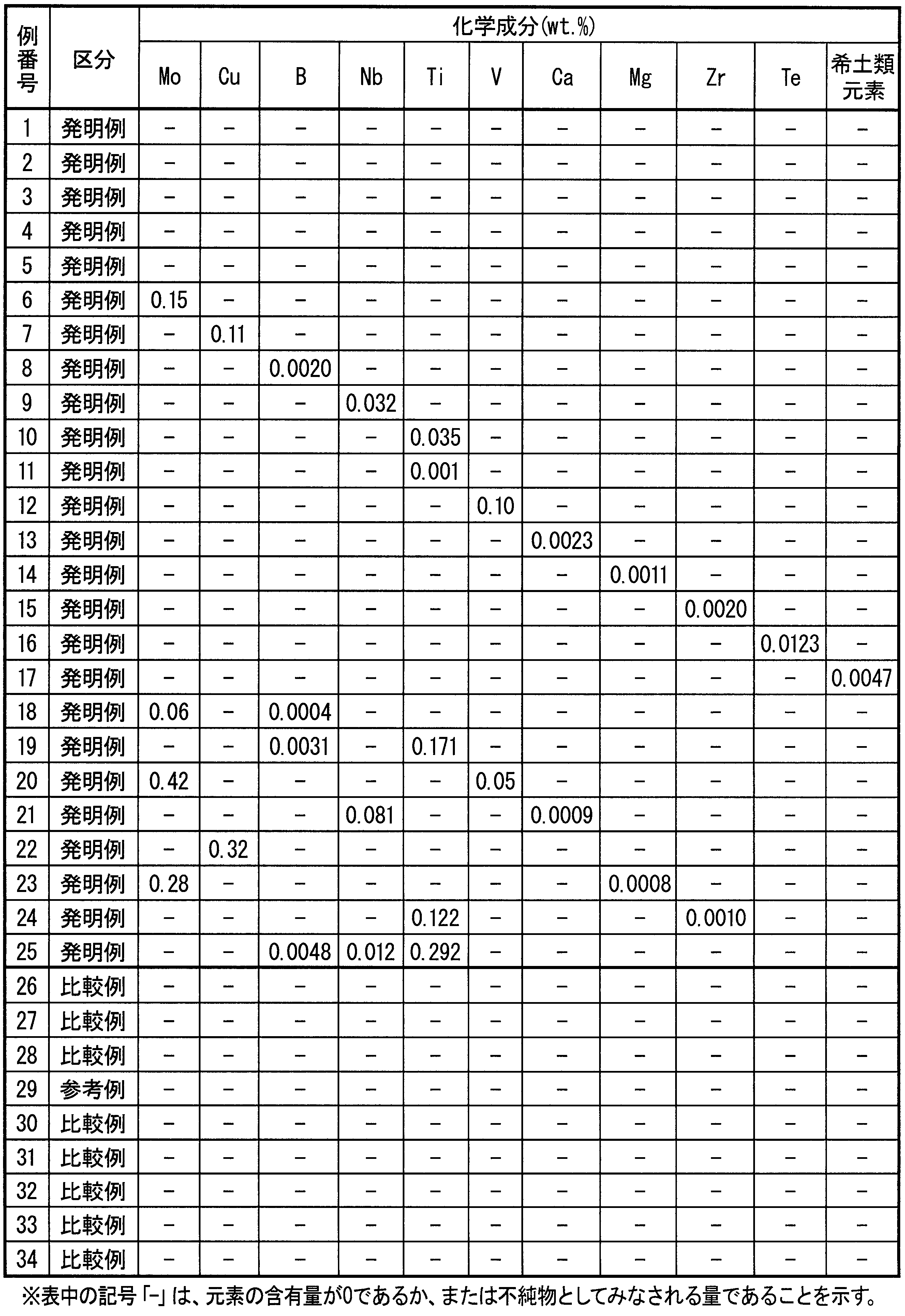
- the steel according to one embodiment of the present invention has a chemical composition of mass%, C: 0.16 to 0.30%, Si: 0.01 to 2.0%, Mn: 0.35 to 1 .45%, Cr: 0.05 to 3.0%, Al: 0.001 to 0.2%, Ni: 0.04 to 5.0%, Sn: 0.015 to 1.0%, S: 0.004 to 0.05%, N: 0.003 to 0.03%, O: 0.005% or less, P: 0.025% or less, Mo: 0 to 1.0%, Cu: 0 to 1 0.0%, B: 0 to 0.005%, Nb: 0 to 0.3%, Ti: 0 to 0.3%, V: 0 to 1.0%, Ca: 0 to 0.01%, Mg : 0-0.01%, Zr: 0-0.05%, Te: 0-0.1%, rare earth elements: 0-0.005%, and the balance: Fe and impurities, Si, Ni, Al And Sn content in mass% [Si%], Ni%], [Al%], when expressed as [Sn%],
- the chemical composition has a mass% of Mo: 0.05 to 1.0%, Cu: 0.01 to 1.0%, and B: 0.0002.
- Mo 0.05 to 1.0%
- Cu 0.01 to 1.0%
- B 0.0002.
- One or two or more of ⁇ 0.005% may be contained.
- the chemical composition has a mass% of Nb: 0.005 to 0.3%, Ti: 0.005 to 0.3%, and V : 0.01 to 1.0% of one or more may be contained.
- the chemical composition is, by mass%, Ca: 0.0005 to 0.01%, Mg: 0.0005 to 0.00. 01%, Zr: 0.0005 to 0.05%, Te: 0.0005 to 0.1%, and rare earth elements: 0.0001 to 0.005%, or one or more of them may be contained. Good.
- a carburized steel part is manufactured using the steel of the present invention, it is not necessary to adjust carburizing conditions for each carburized steel part in order to improve the impact value of the carburized steel part. Accordingly, it is possible to improve the production efficiency by unifying the carburizing method and obtain carburized steel parts having excellent impact values, and the industrial effect of the present invention is extremely large.
- mass% which is a unit related to the content of alloy elements, is simply referred to as “%”.
- % the description related to steel (carburizing steel) applies also to carburized steel parts (carburized material) unless otherwise specified.
- C content determines the intensity
- the lower limit of the C content is 0.16%.
- the upper limit of C content shall be 0.30%.
- the C content is preferably 0.18 to 0.25%.
- Si 0.01 to 2.0%
- Si is an element effective for deoxidation of steel, and is an element effective for imparting strength and hardenability necessary for machine structural parts to carburized steel parts. Furthermore, the increase in the Si content reduces the carburizing properties during carburizing and improves the impact value of the carburized steel part. If the Si content is less than 0.01%, the effect is insufficient. Moreover, when Si content exceeds 2.0%, the decarburization at the time of manufacture will become remarkable and the intensity
- Mn 0.35 to 1.45%
- Mn is an element effective for deoxidation of steel and an element effective for imparting necessary strength and hardenability to steel. If the Mn content is less than 0.35%, the martensitic transformation start temperature becomes high, causing self-tempering and decreasing the hardness. Further, if the Mn content exceeds 1.45%, the retained austenite is stably present in the steel even after the sub-zero treatment, and the strength of the steel is reduced. For the above reasons, the Mn content needs to be in the range of 0.35 to 1.45%.
- the Mn content is preferably 0.50 to 1.10%.
- Cr 0.05-3.0% Cr is an effective element for imparting necessary strength and hardenability to steel. If the Cr content is less than 0.05%, the effect is insufficient. If the Cr content exceeds 3.0%, the effect is saturated. For these reasons, the Cr content needs to be in the range of 0.05 to 3.0%. The Cr content is preferably 0.2 to 1.5%.
- Al 0.001 to 0.2%
- Al is an element effective for deoxidation of steel and is an element that precipitates in the steel as a nitride and has an effect of refining crystal grains. Furthermore, when the Al content is increased, the carburizing property of the steel is lowered, thereby improving the impact value of the carburized steel part. If the Al content is less than 0.001%, the effect is insufficient. On the other hand, if the Al content exceeds 0.2%, the precipitate (Al nitride) becomes coarse, which causes embrittlement of steel and carburized steel parts. For these reasons, the Al content needs to be in the range of 0.001 to 0.2%. A preferable range of the Al content is 0.01 to 0.15%.
- Ni 0.04 to 5.0%
- Ni is an effective element for imparting necessary strength and hardenability to steel. Furthermore, the increase in Ni content reduces the carburizing properties during carburizing, thereby improving the impact value of carburized steel parts. If the Ni content is less than 0.04%, the effect is insufficient. If the Ni content exceeds 5.0%, even if the sub-zero treatment is applied to the steel, the retained austenite is stably present in the steel and the strength of the steel is reduced. For these reasons, the Ni content needs to be in the range of 0.04 to 5.0%. Preferably, the Ni content is 1.0 to 2.0%.
- Sn 0.015 to 1.0%
- S 0.004 to 0.05% S forms MnS in the steel, thereby improving the machinability of the steel. If the S content is less than 0.004%, the effect is insufficient. On the other hand, when the S content exceeds 0.05%, the effect is saturated, and rather, grain boundary segregation occurs and grain boundary embrittlement occurs. For these reasons, the S content needs to be in the range of 0.004 to 0.05%. A preferable range of the S content is 0.01 to 0.04%.
- N 0.003-0.03%
- N combines with Al, Ti, Nb, V, and the like in steel to form nitrides or carbonitrides. These nitrides and carbonitrides have an effect of suppressing coarsening of crystal grains. If the N content is less than 0.003%, the effect is insufficient. If the N content exceeds 0.03%, the effect is saturated. For the above reasons, the N content needs to be in the range of 0.003 to 0.03%. A preferable range of the N content is 0.005 to 0.008%.
- O forms an oxide in steel. This oxide may segregate at the grain boundaries to cause grain boundary embrittlement. O is an element that easily forms brittle fracture by forming hard oxide inclusions in steel.
- the O content needs to be limited to 0.005% or less. A preferable range of the O content is 0.0025% or less. Since it is preferable that the O content is small, the lower limit of the O content is 0%.
- P 0.025% or less P segregates at austenite grain boundaries during carburizing, thereby causing grain boundary fracture. In other words, P decreases the impact value of the carburized steel part. Therefore, it is necessary to limit the P content to 0.025% or less.
- a preferable range of the P content is 0.01% or less. Since it is preferable that the P content is small, the lower limit value of the P content is 0%. However, if P is removed more than necessary, the manufacturing cost increases. Therefore, the substantial lower limit of the P content is usually about 0.004%.
- the steel according to the present embodiment may further contain one or more of Mo, Cu, and B in order to increase the impact value. However, it is not essential to contain these elements.
- Mo 0 to 1.0% Mo suppresses the segregation of P at grain boundaries, and is an effective element for improving the impact value of steel. If the Mo content exceeds 1.0%, the effect is saturated, so the upper limit of the Mo content needs to be 1.0%.
- the lower limit of the Mo content is 0%, but when Mo is contained and the above-described effects are obtained, the Mo content is preferably 0.05% or more. A further preferred range for the Mo content is 0.05 to 0.25%.
- Cu 0 to 1.0%
- Cu is an element effective for improving the hardenability of steel, and is an element for improving the impact value of steel by improving the hardenability. If the Cu content exceeds 1.0%, the hot ductility decreases, so the upper limit of the Cu content needs to be 1.0%.
- the lower limit of the Cu content is 0%, but when Cu is contained to obtain the above-described effects, the Cu content is preferably 0.01% or more. A further preferred range for the Cu content is 0.01 to 0.2%.
- B 0 to 0.005%
- B has a function of suppressing grain boundary segregation of P.
- B also has the effect of improving the grain boundary strength and the intragranular strength, and the effect of improving the hardenability, and these effects improve the impact value of the steel. If the B content exceeds 0.005%, the effect is saturated, so the upper limit of the B content needs to be 0.005%.
- the lower limit of the B content is 0%, but when the above effect is obtained by containing B, the B content is preferably 0.0002% or more.
- a further preferred range for the B content is 0.0005 to 0.003%.
- the steel according to the present embodiment further contains one or more of Nb, Ti, and V within the range shown below in order to prevent a decrease in impact value even when carburized for a long time. May be. However, it is not essential to contain these elements.
- Nb 0 to 0.3% Nb produces Nb carbonitride in the steel. Even when so-called high-temperature carburizing with a carburizing temperature of 980 ° C. or higher is applied and when so-called long-term carburizing with a carburizing time of 10 hours or longer is applied, a suitable amount of Nb carbonitride is present in the steel. As a result, the austenite grains can be refined and the impact value can be prevented from decreasing. If the Nb content exceeds 0.3%, the machinability deteriorates, so the upper limit of the Nb content is set to 0.3%. The lower limit value of the Nb content is 0%, but when the above effect is obtained by containing Nb, the Nb content is preferably 0.005% or more. A further preferred range for the Nb content is 0.02 to 0.05%.
- Ti 0 to 0.3% Ti produces fine TiC and / or TiCS in the steel.
- high-temperature carburizing with a carburizing temperature of 980 ° C. or higher is applied, and when so-called long-term carburizing with a carburizing time of 10 hours or longer is applied, suitable amounts of TiC and TiCS are present in the steel. As a result, the austenite grains can be made finer and the impact value of the steel can be prevented from being lowered.
- the Ti content exceeds 0.3%, TiN-based precipitates increase and the fatigue properties of the steel deteriorate.
- the upper limit of Ti content needs to be 0.3%.
- the lower limit of the Ti content is 0%, but when Ti is contained to obtain the above-described effects, the Ti content is preferably set to 0.005% or more. A further preferred range for the Ti content is 0.02 to 0.2%.
- V 0 to 1.0% V produces V carbonitrides in the steel. Even when so-called high-temperature carburization with a carburizing temperature of 980 ° C. or higher is applied and when so-called long-time carburizing with a carburizing time of 10 hours or longer is applied, a suitable amount of V carbonitride is present in the steel. As a result, the austenite grains can be made finer and the impact value of the steel can be prevented from being lowered. If the V content exceeds 1.0%, the machinability of the steel is deteriorated. For the above reason, the upper limit of the V content needs to be 1.0%. The lower limit of the V content is 0%, but when V is contained and the above-described effects are obtained, the V content is preferably set to 0.01% or more. A further preferred range for the V content is 0.03-0.1%.
- the steel according to the present embodiment may further contain one or more of Ca, Mg, Zr, Te, and rare earth elements within the following ranges. . However, it is not essential to contain these elements.
- Ca 0 to 0.01% Ca lowers the melting point of the oxide and softens due to temperature rise during cutting, thus improving machinability. However, if the Ca content exceeds 0.01%, a large amount of CaS is generated, and the machinability deteriorates. For the above reasons, it is desirable to set the upper limit of Ca content to 0.01%.
- the lower limit of the Ca content is 0%, but when Ca is contained to obtain the above-described effects, the Ca content is preferably 0.0005% or more. A further preferred range for the Ca content is 0.0005 to 0.0015%.
- Mg 0 to 0.01%
- Mg is a deoxidizing element and generates an oxide in steel. Further, the Mg-based oxide formed by Mg tends to be a nucleus of MnS crystallization and / or precipitation. Further, the Mg sulfide becomes a composite sulfide of Mn and Mg, thereby spheroidizing MnS. Thus, Mg is an effective element for controlling the dispersion of MnS and improving machinability. However, if the Mg content exceeds 0.01%, a large amount of MgS is generated and the machinability of the steel is lowered. Therefore, it is desirable to set the upper limit of the Mg content to 0.01%.
- the lower limit of the Mg content is 0%, but when Mg is contained to obtain the above-described effects, the Mg content is preferably set to 0.0005% or more. A further preferred range for the Mg content is 0.0005 to 0.0015%.
- Zr 0 to 0.05%
- Zr is a deoxidizing element and generates an oxide. Furthermore, the Zr-based oxide formed by Zr tends to be a nucleus of MnS crystallization and / or precipitation. Thus, Zr is an effective element for controlling the dispersion of MnS and improving the machinability. However, if the amount of Zr exceeds 0.05%, the effect is saturated, so the upper limit of the Zr content is preferably set to 0.05%.
- the lower limit of the Zr content is 0%. However, when the above effect is obtained by containing Zr, the Zr content is preferably set to 0.0005% or more. In order to promote the spheroidization of MnS, the lower limit value of the Zr content is particularly preferably more than 0.003%.
- Te 0 to 0.1% Te promotes the spheroidization of MnS and improves the machinability of the steel. Since the effect is saturated when the Te content exceeds 0.1%, the upper limit of the Te content is preferably set to 0.1%. The lower limit of the Te content is 0%, but when Te is contained to obtain the above-described effects, the Te content is preferably set to 0.0005% or more. A further preferred range for the Te content is 0.0005 to 0.0015%.
- the rare earth element is an element that promotes the production of MnS by producing sulfides in the steel and these sulfides become MnS precipitation nuclei, and improves the machinability of the steel.
- the upper limit of the total content of rare earth elements needs to be 0.005%.
- the lower limit of the total content of rare earth elements is 0%, but when the above effects are obtained by adding rare earth elements, the total content of rare earth elements is preferably 0.0001% or more.
- a further preferable range of the total content of rare earth elements is 0.001 to 0.003%.
- the steel according to this embodiment contains the above-described alloy components, and the balance contains Fe and impurities. It is permissible for elements other than the above-mentioned alloy components to be mixed into the steel as impurities from the raw materials and production equipment as long as the mixed amount is at a level that does not affect the properties of the steel.
- each alloy component included in the steel according to the present embodiment has been described above. However, by controlling the content of each alloy component individually, a steel for obtaining a carburized steel part having a sufficient impact value under a single carburizing condition regardless of the shape of the carburized steel part is realized. It is not possible. The present inventors have further found that it is necessary to control the content of the alloy component based on the formula (1).
- the impact test piece 3 was defined.
- the carburizing condition hereinafter referred to as the reference carburizing
- the processing temperature is 930 ° C.
- the processing time is 5 hours
- the carbon potential is 0.8.
- the Charpy absorbed energy at 25 ° C. of the carburized material obtained by performing gas carburizing in the case of gas carburizing and then tempering with a tempering temperature of 150 ° C.
- the impact value ratio is determined by the Charpy at 25 ° C. of the carburized material obtained by carburizing and tempering the Charpy impact test piece 3 in accordance with the carburizing conditions (that is, the reference carburizing conditions) applied when obtaining the reference impact value. Absorbed energy was defined as the value divided by the reference impact value.
- the reference steel described above is a steel having a chemical composition corresponding to SCr420, which is generally used as a gear steel, and is the same as that of Comparative Example 26 described later.
- the gas carburizing performed under the above-mentioned standard carburizing conditions is a general carburizing process performed for the manufacture of machine structural parts.
- the shape of the Charpy impact test piece 3 is different from the shape of a general Charpy impact test piece (for example, the shape defined in JIS-Z2242 “Charpy impact test method for metal material”).
- the shape of the notch 2 of the Charpy impact test piece 3 is determined with the intention of simulating the shape of the tooth root portion of the gear. By performing the Charpy impact test on the test piece having such a notch, it is possible to estimate the impact resistance characteristics at the tooth root portion of the gear.
- a test piece having such a notch is widely used as a shape of a test piece for measuring the impact resistance characteristics of a carburized steel material as described in, for example, Japanese Patent Application Laid-Open No. 2013-40376.
- the Charpy absorbed energy was measured according to JIS-Z2242 “Charpy impact test method for metal materials” except for the shape of the Charpy impact test piece 3.
- the implementation temperature of the Charpy impact test was 25 ° C.
- the Charpy impact test piece 3 was produced by machining.
- the present inventors forged, machined, and carburized various steels containing alloy elements within the above-described component ranges (however, the provisions relating to Formula 1 were not considered), and carburized materials obtained from these steels.
- the impact value ratio was determined.
- the present inventors measured the surface C density
- the Charpy impact test piece 3 is formed along the notch surface (surface on which the notch is formed) of the Charpy impact test piece 3 subjected to gas carburizing treatment under the standard carburizing condition and the direction perpendicular to the notch 2.
- the cut surface was cut and polished.
- FIG. 3 shows a schematic view of the cut surface.
- the C concentration was measured at intervals of 5 ⁇ m from the bottom surface of the notch 2 in the region of 5 to 50 ⁇ m (surface C concentration measurement region 1) in the height direction of the Charpy impact test piece 3.
- the C concentration was measured by EPMA.
- the size of the measurement point (EPMA electron beam diameter) was set to 5 ⁇ m.
- a value obtained by averaging the ten measurement data obtained as described above was defined as the surface C concentration.
- the unit of the surface C concentration is mass%.
- the surface C concentration changed according to the amount of alloy element added.
- the present inventors have found out. This phenomenon is considered to be caused by a chemical interaction between the alloy element and C that enters the steel surface by carburization. Si, Ni, Al, and Sn have a particularly strong influence on the surface C concentration, and the surface C concentration decreased as the content of these elements increased.
- the carburizability of the steel can be controlled by defining the relationship among the contents of Si, Ni, Al, and Sn by Equation 1. it can.
- the impact value ratio needs to be 1.2 or more for the following reason.
- the design of the parts is changed so that the impact fracture resistance is ensured while the amount of material used is suppressed. be able to.
- the impact value is improved by 20% with respect to the above-mentioned reference impact value (impact value of SCr420 carburized under general carburizing conditions). It is said that it is necessary.
- FIG. 4 is a semilogarithmic graph showing the correlation between the surface C concentration of the carburized material and the impact value ratio.
- the impact value ratio of the data points below the broken line is less than 1.2.
- the surface C concentration of the carburized material subjected to gas carburizing under the standard carburizing condition is controlled to 0.75% or less. I found it necessary to do.
- the surface C concentration was subjected to multiple regression analysis with the contents of Si, Ni, Al, and Sn as factors.
- the following formulas (1 ′) and (2 ′) are used as critical conditions for obtaining a carburized material having a surface C concentration of 0.75 mass% when gas carburization is performed under the standard carburizing conditions.
- FIG. 5 is a graph showing the relationship between the ⁇ value and the surface C concentration and the relationship between the ⁇ value and the impact value ratio.
- the ⁇ value of the data point to the left of the left broken line is less than 8.5
- the ⁇ value of the data point to the right of the right broken line is more than 42.
- the surface C concentration becomes 0.75 mass% or less when gas carburizing is performed under the standard carburizing conditions.
- the ⁇ value increases, the surface C concentration of the carburized material decreases, and accordingly, the impact value of the carburized material increases.
- the ⁇ value is 12 or more.
- the surface hardness of the carburized material is desirably higher than HV550.
- the surface C concentration of the carburized material that has been gas carburized under the standard carburizing condition needs to be 0.4% by mass or more.
- the ⁇ value needs to be 42 or less.
- the surface C concentration of the carburized material that has been gas carburized under the standard carburizing conditions is more preferably 0.55% by mass or more, and in order to achieve this, the ⁇ value is preferably 25 or less. .
- the carburizing method for obtaining carburized steel parts from the steel according to the present embodiment is preferably gas carburizing (which may be either a modified furnace method or a dropping method).
- gas carburizing which may be either a modified furnace method or a dropping method.
- nitriding may be performed.
- the effective hardened layer depth may be considered as an evaluation standard for carburized steel parts, the characteristics required for parts such as vehicle gears such as differential gears are higher in surface hardness than effective hardened layer depth. Strongly related to. Therefore, if the steel according to the present embodiment, which can control the surface C concentration of the carburized steel part to an appropriate level and thereby optimize the surface hardness, an advantageous effect on industrial use can be obtained.
- the steel according to the present embodiment is, for example, first formed into a round bar steel by hot rolling, then subjected to forging or cutting to form a gear or the like, and further carburized and quenched to be a carburized steel part. Good.
- the conditions in the examples are one example of conditions used for confirming the feasibility and effects of the present invention, and the present invention is based on this one example of conditions. It is not limited.
- the present invention can adopt various conditions as long as the object of the present invention is achieved without departing from the gist of the present invention.
- This test piece shape is the same as the Charpy impact test piece 3 described above.
- the Charpy impact test piece was carburized.
- gas carburizing was performed under carburizing conditions in which the processing temperature was 930 ° C., the processing time was 5 hours, and the carbon potential was 0.8.
- This processing condition is the same as the reference carburizing condition described above.
- gas carburizing was performed under carburizing conditions in which the processing temperature was 930 ° C., the processing time was 5 hours, and the carbon potential was 0.6.
- Tempering was carried out under conditions where the tempering temperature was 150 ° C. and the tempering time was 90 minutes. After tempering, the surface C concentration of each sample was measured.
- the method for measuring the surface C concentration is as follows. First, the Charpy impact test piece was cut along a notch surface (surface on which a notch was formed) and a direction perpendicular to the notch of the Charpy impact test piece, and the cut surface was polished. Next, the C concentration was measured at intervals of 5 ⁇ m from the bottom surface of the notch 2 in the region of 5 to 50 ⁇ m (surface C concentration measurement region 1) in the height direction of the Charpy impact test piece. The C concentration was measured by EPMA. The size of the measurement point (EPMA electron beam diameter) was set to 5 ⁇ m. A value obtained by averaging the ten measurement data obtained as described above was defined as the surface C concentration. The unit of the surface C concentration is mass%.
- the Charpy impact test was implemented after tempering and Charpy absorbed energy (impact value) was measured.
- the Charpy impact test was performed at a test temperature of 25 ° C. in accordance with the method defined in JIS-Z2242, except for the notch shape of the Charpy impact test piece.
- the impact value ratio of each sample was calculated by dividing the impact value of each sample by the impact value of Comparative Example 26. Note that the steel of Comparative Example 26 is the reference steel described above.
- a wear test was performed on each sample to measure the wear depth.
- Comparative Example 26 has a chemical composition corresponding to SCr420 defined in JIS-G 4053, which is generally used as gear steel, and is 21 ⁇ [Si%] + 5 ⁇ [Ni%] + 40 ⁇ [Sn%] + 32 ⁇ . [Al%] was 6.3, and when gas carburizing was performed under the standard carburizing conditions, the impact value was 10 J / cm 2 .
- the impact value ratios of Invention Examples 1 to 25 were all 1.3 or more, and it was clear that they had excellent impact strength.
- Invention Example 1 is good because 21 ⁇ [Si%] + 5 ⁇ [Ni%] + 40 ⁇ [Sn%] + 32 ⁇ [Al%] is 41.1 and the surface C concentration is 0.46%. Shock value was obtained.
- Comparative Examples 26 to 35 did not have desirable characteristics. Since Comparative Examples 26 and 28 did not contain Sn, they were excessively carburized and had only low impact values compared to the Examples. Further, in Comparative Example 31, since the Sn content was below the specified range of the present invention, similarly to Comparative Examples 26 and 28, carburization was excessively performed, and only a low impact value was obtained as compared with the Examples. There wasn't. Regarding Comparative Example 27, the content of each alloy element is within the specified range of the present invention, but 21 ⁇ [Si%] + 5 ⁇ [Ni%] + 40 ⁇ [Sn%] + 32 ⁇ [Al%] is the present invention. The specified range was exceeded.
- Comparative Example 27 the abrasion resistance of Comparative Example 27 was low.
- Comparative Example 30 the content of each alloy element is within the specified range of the present invention, but 21 ⁇ [Si%] + 5 ⁇ [Ni%] + 40 ⁇ [Sn%] + 32 ⁇ [Al%] is the present invention.
- the carburization was excessive because it was below the specified range.
- the comparative example 30 had only a low impact value compared with the Example.
- Comparative Example 32 since the Sn content exceeded the specified range of the present invention, the hot ductility was lowered. Thereby, in Comparative Example 32, cracks frequently occurred on the surface of the obtained carburized material.
- Comparative Example 33 since the Ni content exceeded the specified range of the present invention, the strength decreased. Thereby, the abrasion resistance of Comparative Example 33 was low.
- Comparative Example 34 since the Al content exceeded the specified range of the present invention, embrittlement occurred. Thereby, the impact value ratio of the comparative example 34 was low.
- Reference Example 29 is the same steel as Comparative Example 26, but the carburizing conditions are different and the carbon potential (carburizing treatment of 0.6) is set low, so the surface C concentration is low and a good impact value is obtained. You can see that However, setting a low carbon potential in actual production is not suitable because it leads to a decrease in productivity.
Landscapes
- Chemical & Material Sciences (AREA)
- Engineering & Computer Science (AREA)
- Materials Engineering (AREA)
- Mechanical Engineering (AREA)
- Metallurgy (AREA)
- Organic Chemistry (AREA)
- Physics & Mathematics (AREA)
- Thermal Sciences (AREA)
- Crystallography & Structural Chemistry (AREA)
- Chemical Kinetics & Catalysis (AREA)
- Solid-Phase Diffusion Into Metallic Material Surfaces (AREA)
- Heat Treatment Of Articles (AREA)
Abstract
Description
本願は、2012年12月28日に、日本にて出願された特願2012-288131号に基づき優先権を主張し、その内容をここに援用する。
表面C濃度の低減は、浸炭処理の際にカーボンポテンシャルを低下させることにより実現可能である。しかし、浸炭炉を用いた実際の生産工程においてこれを実施することは難しい。何故なら、実際の生産工程では、浸炭炉は、用途が異なる種々の部品に対して、同時に、且つ連続して大量に処理を行う必要があるからである。浸炭を行う部品に求められる特性は、上述のように耐衝撃特性に限定されない。例えば、耐摩耗性および疲労強度などの特性も浸炭鋼部品には求められる。したがって、浸炭処理の際にカーボンポテンシャルを低下させることは、耐衝撃特性が主に求められる部品に対しては有効であるが、疲労強度が主に求められる部品において悪影響を及ぼし、疲労強度の低下による問題を発生させる。もし、浸炭性があまり発揮されない条件で浸炭することによって浸炭鋼部品の表面C濃度を制御することを試みる場合、部品ごとに浸炭条件を調整することが必要とされる。しかし、このことは生産性の低下につながるので、産業利用上好ましくない。
従って、種々の部品の浸炭に対応することができる強めの浸炭条件で浸炭処理を行ったとしても、Cの浸入量を適切な水準に制御することができる浸炭用鋼が求められる。
特許文献1~4の開示技術では、衝撃値の向上と生産性低下の回避とを両立するニーズ、具体的には部品ごとに浸炭条件を調整することなく耐衝撃特性に優れる浸炭鋼部品を得るというニーズには充分に応えることができなかった。
本発明は、浸炭鋼部品の材料として使用したときに、衝撃値(耐衝撃特性)と耐摩耗性との両方に優れる浸炭鋼部品を得ることができ、かつ、その浸炭鋼部品の製造時には浸炭条件の変更を必要としない鋼を提供するものである。
42≧21×[Si%]+5×[Ni%]+40×[Sn%]+32×[Al%]≧8.5・・・(A)
42≧21×[Si%]+5×[Ni%]+40×[Sn%]+32×[Al%]≧8.5・・・(A)
C含有量は、浸炭鋼部品の芯部の強度を決定し、さらに有効硬化層深さにも影響する。所要の芯部強度を確保するために、C含有量の下限値を0.16%とする。一方、C含有量が多すぎると製造性が低下するので、C含有量の上限値を0.30%とする。C含有量は、好ましくは0.18~0.25%である。
Siは、鋼の脱酸に有効な元素であるとともに、機械構造用部品として必要な強度及び焼入れ性を浸炭鋼部品に付与するために有効な元素である。さらに、Si含有量の増加により、浸炭時の浸炭性が低下して、浸炭鋼部品の衝撃値が向上する。Si含有量が0.01%未満では、その効果が不十分である。また、Si含有量が2.0%を超えると、製造時の脱炭が著しくなり、浸炭鋼部品の強度および有効硬化層深さが不足する。以上の理由によって、Si含有量を0.01~2.0%の範囲内にする必要がある。Si含有量は、好ましくは0.2~1.5%である。
Mnは鋼の脱酸に有効な元素であるとともに、必要な強度及び焼入れ性を鋼に付与するために有効な元素である。Mn含有量が0.35%未満では、マルテンサイト変態開始温度が高くなり、セルフテンパーを起こし、硬さが低下する。また、Mn含有量が1.45%を超えると、サブゼロ処理後であっても残留オーステナイトが安定的に鋼中に存在して、鋼の強度が低下する。以上の理由によって、Mn含有量を0.35~1.45%の範囲内にする必要がある。Mn含有量は、好ましくは、0.50~1.10%である。
Crは、必要な強度及び焼入れ性を鋼に付与するために有効な元素である。Cr含有量が0.05%未満では、その効果が不十分である。Cr含有量が3.0%を超えると、その効果が飽和する。以上の理由によって、Cr含有量を0.05~3.0%の範囲内にする必要がある。Cr含有量は、好ましくは0.2~1.5%である。
Alは、鋼の脱酸に有効な元素であるとともに、窒化物となって鋼中に析出して、結晶粒微細化効果を奏する元素である。さらに、Al含有量が増加すると、鋼の浸炭性が低下し、これにより浸炭鋼部品の衝撃値が向上する。Al含有量が0.001%未満では、その効果が不十分である。また、Al含有量が0.2%を超えると、析出物(Al窒化物)が粗大化し、鋼および浸炭鋼部品の脆化の原因となる。以上の理由によって、Al含有量を0.001~0.2%の範囲内にする必要がある。Al含有量の好適範囲は0.01~0.15%である。
Niは、必要な強度及び焼入れ性を鋼に付与するために有効な元素である。さらに、Ni含有量の増加により、浸炭時の浸炭性が低下し、これにより浸炭鋼部品の衝撃値が向上する。Ni含有量が0.04%未満では、その効果が不十分である。Ni含有量が5.0%を超えると、サブゼロ処理を鋼に施しても、残留オーステナイトが鋼中に安定に存在して、鋼の強度が低下する。以上の理由によって、Ni含有量を0.04~5.0%の範囲内にする必要がある。好ましくは、Ni含有量は1.0~2.0%である。
Sn含有量の増加により、浸炭時の浸炭性が低下し、これにより浸炭鋼部品の衝撃値が向上する。Sn含有量が0.015%未満では、その効果は不十分である。一方、Sn含有量が1.0%を超えると、鋼の熱間延性が低下する。以上の理由によって、Snの含有量を0.015~1.0%の範囲内にする必要がある。Sn含有量の好適範囲は0.02~0.1%である。
Sは、鋼中でMnSを形成し、これにより鋼の被削性を向上させる。S含有量が0.004%未満では、その効果は不十分である。一方、S含有量が0.05%を超えると、その効果は飽和し、むしろ粒界偏析を起こし粒界脆化を引き起こす。以上の理由から、Sの含有量を0.004~0.05%の範囲内にする必要がある。S含有量の好適範囲は0.01~0.04%である。
Nは、鋼中でAl、Ti、Nb、およびV等と結合して窒化物又は炭窒化物を生成する。これら窒化物および炭窒化物は結晶粒の粗大化を抑制する効果を有する。N含有量が0.003%未満では、その効果が不十分である。N含有量が0.03%を超えると、その効果が飽和する。以上の理由によって、N含有量を0.003~0.03%の範囲内にする必要がある。N含有量の好適範囲は0.005~0.008%である。
Oは、鋼中で酸化物を形成する。この酸化物は、粒界偏析して粒界脆化を起こす場合がある。また、Oは鋼中で硬い酸化物系介在物を形成して脆性破壊を起こしやすくする元素である。O含有量は0.005%以下に制限される必要がある。O含有量の好適範囲は0.0025%以下である。O含有量が少ない方が好ましいので、O含有量の下限値は0%である。
Pは、浸炭時にオーステナイト粒界に偏析し、それにより粒界破壊を引き起こす。つまり、Pは浸炭鋼部品の衝撃値を低下させてしまう。したがって、P含有量を0.025%以下に制限する必要がある。P含有量の好適範囲は0.01%以下である。P含有量が少ない方が好ましいので、P含有量の下限値は0%である。しかし、Pの除去を必要以上に行った場合、製造コストが増大する。従って、P含有量の実質的な下限値は約0.004%となるのが通常である。
Moは、Pが粒界に偏析することを抑制するので、鋼の衝撃値の向上のために有効な元素である。Mo含有量が1.0%を超えると、その効果が飽和するので、Mo含有量の上限を1.0%とする必要がある。Mo含有量の下限値は0%であるが、Moを含有させて上述の効果を得る場合には、Mo含有量を0.05%以上とすることが好ましい。Mo含有量のさらなる好適範囲は0.05~0.25%である。
Cuは、鋼の焼入れ性の向上に有効な元素であり、また、焼入れ性の向上によって鋼の衝撃値を向上させる元素である。Cu含有量が1.0%を超えると、熱間延性が低下するので、Cu含有量の上限を1.0%とする必要がある。Cu含有量の下限値は0%であるが、Cuを含有させて上述の効果を得る場合には、Cu含有量を0.01%以上とすることが好ましい。Cu含有量のさらなる好適範囲は0.01~0.2%である。
Bは、Pの粒界偏析を抑制する働きを有する。また、Bは粒界強度および粒内強度の向上効果、及び焼入れ性の向上効果も有し、これら効果は鋼の衝撃値を向上させる。B含有量が0.005%を超えると、その効果は飽和するので、B含有量の上限値を0.005%とする必要がある。B含有量の下限値は0%であるが、Bを含有させて上述の効果を得る場合には、B含有量を0.0002%以上とすることが好ましい。B含有量のさらなる好適範囲は0.0005~0.003%である。
Nbは、鋼中にNb炭窒化物を生成する。浸炭温度が980℃以上のいわゆる高温浸炭が適用された場合、および浸炭時間が10時間以上のいわゆる長時間浸炭が適用された場合においても、好適な量のNb炭窒化物が鋼中に存在することにより、オーステナイト粒を細粒化することができ、衝撃値の低下が防止できる。Nb含有量が0.3%を超えると被削性が劣化するので、Nb含有量の上限を0.3%とする。Nb含有量の下限値は0%であるが、Nbを含有させて上述の効果を得る場合には、Nb含有量を0.005%以上とすることが好ましい。Nb含有量のさらなる好適範囲は0.02~0.05%である。
Tiは、鋼中で微細なTiC、および/またはTiCSを生成する。浸炭温度が980℃以上のいわゆる高温浸炭が適用された場合、および浸炭時間が10時間以上のいわゆる長時間浸炭が適用された場合においても、好適な量のTiC、およびTiCSが鋼中に存在することにより、オーステナイト粒を細粒化することができ、鋼の衝撃値の低下が防止できる。Ti含有量が0.3%を越えると、TiN主体の析出物が多くなって、鋼の疲労特性が低下する。以上の理由から、Ti含有量の上限値を0.3%とする必要がある。Ti含有量の下限値は0%であるが、Tiを含有させて上述の効果を得る場合には、Ti含有量を0.005%以上とすることが好ましい。Ti含有量のさらなる好適範囲は0.02~0.2%である。
Vは、鋼中でV炭窒化物を生成する。浸炭温度が980℃以上のいわゆる高温浸炭が適用された場合、および浸炭時間が10時間以上のいわゆる長時間浸炭が適用された場合においても、好適な量のV炭窒化物が鋼中に存在することにより、オーステナイト粒を細粒化することができ、鋼の衝撃値の低下が防止できる。V含有量が1.0%を超えると、鋼の被削性を劣化させる。以上の理由によって、V含有量の上限値を1.0%とする必要がある。V含有量の下限値は0%であるが、Vを含有させて上述の効果を得る場合には、V含有量を0.01%以上とすることが好ましい。V含有量のさらなる好適範囲は、0.03~0.1%である。
Caは、酸化物の融点を低下させ、切削加工の際に温度上昇により軟質化するので、被削性を改善する。しかし、Ca含有量が0.01%を超えるとCaSが多量に生成されて、被削性が低下する。以上の理由によって、Ca含有量の上限値を0.01%とするのが望ましい。Ca含有量の下限値は0%であるが、Caを含有させて上述の効果を得る場合には、Ca含有量を0.0005%以上とすることが好ましい。Ca含有量のさらなる好適範囲は、0.0005~0.0015%である。
Mgは脱酸元素であり、鋼中に酸化物を生成する。さらに、Mgが形成するMg系酸化物は、MnSの晶出および/または析出の核になりやすい。また、Mgの硫化物は、MnおよびMgの複合硫化物となることにより、MnSを球状化させる。このように、MgはMnSの分散を制御し、被削性を改善するために有効な元素である。しかし、Mg含有量が0.01%を超えると、MgSが大量に生成され、鋼の被削性が低下するので、Mg含有量の上限値を0.01%とするのが望ましい。Mg含有量の下限値は0%であるが、Mgを含有させて上述の効果を得る場合には、Mg含有量を0.0005%以上とすることが好ましい。Mg含有量のさらなる好適範囲は、0.0005~0.0015%である。
Zrは脱酸元素であり、酸化物を生成する。さらに、Zrが形成するZr系酸化物はMnSの晶出および/または析出の核になりやすい。このように、Zrは、MnSの分散を制御し、被削性を改善するために有効な元素である。しかし、Zr量が0.05%を超えると、その効果が飽和するので、Zr含有量の上限値を0.05%とするのが望ましい。Zr含有量の下限値は0%であるが、Zrを含有させて上述の効果を得る場合には、Zr含有量を0.0005%以上とすることが好ましい。また、MnSの球状化を促進するには、Zr含有量の下限値は、0.003%超とすることが特に好ましい。
Teは、MnSの球状化を促進するので、鋼の被削性を改善する。Te含有量が0.1%を超えるとその効果が飽和するので、Te含有量の上限値を0.1%とすることが好ましい。Te含有量の下限値は0%であるが、Teを含有させて上述の効果を得る場合には、Te含有量を0.0005%以上とすることが好ましい。Te含有量のさらなる好適範囲は、0.0005~0.0015%である。
希土類元素は、鋼中に硫化物を生成し、この硫化物がMnSの析出核となることで、MnSの生成を促進する元素であり、鋼の被削性を改善する。しかし、希土類元素の合計含有量が0.005%を超えると、硫化物が粗大になり、鋼の疲労強度を低下させるので、希土類元素の合計含有量の上限値を0.005%にする必要がある。希土類元素の合計含有量の下限値は0%であるが、希土類元素を含有させて上述の効果を得る場合には、希土類元素の合計含有量を0.0001%以上とすることが好ましい。希土類元素の合計含有量のさらなる好適範囲は、0.001~0.003%である。
式(1)において、[Si%]、[Ni%]、[Sn%]、および[Al%]は、Si、Ni、Sn、およびAlの含有量を質量%で示すものである。以下に、式(1)の導出の根拠に関して説明する。
まず、C:0.20質量%、Si:0.24質量%、Mn:0.79質量%、P:0.014質量%、S:0.015質量%、Cr:1.21質量%、Al:0.031質量%、Ni:0.05質量%、Sn:0質量%、N:0.005質量%、およびO:0.001質量%を含有し、残部がFeおよび不純物である浸炭用鋼を基準鋼と定義した。次に、図2に示される、外形寸法が10mm×10mm×55mmであり、且つ曲率半径10mmおよび深さ2mmの円弧状の切欠き(ノッチ)を有するシャルピー衝撃試験片を、本実施形態におけるシャルピー衝撃試験片3と定義した。基準鋼を材料として形成されたシャルピー衝撃試験片3に対して、先ず処理温度が930℃であり、処理時間が5時間であり、且つカーボンポテンシャルが0.8である浸炭条件(以下、基準浸炭条件と称する場合がある)でガス浸炭を行い、次いで焼戻し温度が150℃であり且つ焼戻し時間が90分である焼戻しを行って得られる浸炭材の25℃でのシャルピー吸収エネルギーを、基準衝撃値と定義した。
さらに、衝撃値比を、基準衝撃値を得る際に適用された浸炭条件(すなわち、基準浸炭条件)に従ってシャルピー衝撃試験片3に浸炭および焼戻しを行って得られた浸炭材の25℃でのシャルピー吸収エネルギーを、基準衝撃値で除した値と定義した。
上述の基準鋼は、歯車用鋼として一般に用いられる、SCr420に相当する化学組成を有する鋼であり、後述する比較例26の鋼と同一である。上述の基準浸炭条件の下で行われるガス浸炭は、機械構造用部品の製造のために行われる一般的な浸炭処理である。
上述のシャルピー衝撃試験片3の側面形状(切欠きの延伸方向に垂直な断面の形状)を図2に示す。切欠き2の曲率半径は10mmである。シャルピー衝撃試験片3の形状は、一般的なシャルピー衝撃試験片の形状(例えば、JIS-Z2242「金属材料のシャルピー衝撃試験方法」中に規定された形状)とは異なる。シャルピー衝撃試験片3の切欠き2の形状は、歯車の歯元部の形状を模擬することを意図して決定されている。このような切欠きを有する試験片にシャルピー衝撃試験を行うことにより、歯車の歯元部における耐衝撃特性を推定することができる。このような切欠きを有する試験片は、例えば日本国特開2013-40376号公報に記載されているように、浸炭した鋼材の耐衝撃特性を測定する試験片形状としては広く用いられている。シャルピー吸収エネルギーの測定は、シャルピー衝撃試験片3の形状以外は、JIS-Z2242「金属材料のシャルピー衝撃試験方法」に準じて行われた。シャルピー衝撃試験の実施温度は25℃とした。シャルピー衝撃試験片3は機械加工によって作成された。
表面C濃度の測定方法を以下に説明する。先ず、基準浸炭条件下でガス浸炭処理が行われたシャルピー衝撃試験片3のノッチ面(切欠きが形成された面)および切欠き2に対して垂直な方向に沿ってシャルピー衝撃試験片3を切断し、切断面を研磨した。図3に、切断面の概略図を示す。次に、切欠き2の底部表面から、シャルピー衝撃試験片3の高さ方向に向かって5~50μmの領域(表面C濃度測定領域1)において、5μm間隔でC濃度を測定した。C濃度の測定はEPMAによって行った。測定点の大きさ(EPMAの電子ビーム径)はφ5μmとした。これにより得られた10個の測定データを平均した値を、表面C濃度とした。表面C濃度の単位は質量%である。
上述したように、衝撃値比と表面C濃度との間には相関関係がある。図4は、浸炭材の表面C濃度と衝撃値比との相関関係を示す片対数グラフである。図4において、破線より下のデータポイントの衝撃値比は1.2未満である。図4に示されるように、1.2以上の衝撃値比を有する浸炭材を得るためには、基準浸炭条件でガス浸炭が行われた浸炭材の表面C濃度を0.75%以下に制御する必要があることが分かった。
ここで、表面C濃度を、Si、Ni、Al、およびSnの各含有量を因子として重回帰分析した。その結果、基準浸炭条件でガス浸炭が行われた場合に表面C濃度が0.75質量%である浸炭材を得るための臨界的な条件として、下記式(1’)および式(2’)を得た。
21×[Si%]+5×[Ni%]+40×[Sn%]+32×[Al%]=α・・・ (1’)
α=8.5・・・ (2’)
なお、浸炭鋼部品の評価基準として有効硬化層深さが検討される場合もあるが、差動歯車などの車両用歯車のような部品に求められる特性は、有効硬化層深さよりも表面硬さに強く関連する。従って、浸炭鋼部品の表面C濃度を適切な水準に制御し、これにより表面硬さを最適化することができる本実施形態に係る鋼を用いれば、産業利用上有利な効果が得られる。
焼戻し後に、各試料の表面C濃度を測定した。表面C濃度の測定方法は以下の通りである。先ず、シャルピー衝撃試験片のノッチ面(切欠きが形成された面)および切欠きに対して垂直な方向に沿ってシャルピー衝撃試験片を切断し、切断面を研磨した。次に、切欠き2の底部表面から、シャルピー衝撃試験片の高さ方向に向かって5~50μmの領域(表面C濃度測定領域1)において、5μm間隔でC濃度を測定した。C濃度の測定はEPMAによって行った。測定点の大きさ(EPMAの電子ビーム径)はφ5μmとした。これにより得られた10個の測定データを平均した値を、表面C濃度とした。表面C濃度の単位は質量%である。
また、焼戻し後にシャルピー衝撃試験を実施して、シャルピー吸収エネルギー(衝撃値)を測定した。シャルピー衝撃試験は、シャルピー衝撃試験片のノッチの形状以外はJIS-Z2242に規定の方法に則って、試験温度25℃で実施した。
さらに、各試料の衝撃値を比較例26の衝撃値で除すことにより、各試料の衝撃値比を算出した。なお、比較例26の鋼は、上述した基準鋼である。
加えて、各試料の耐摩耗性を評価するために、各試料に摩耗試験を行って摩耗深さを測定した。上述の方法で作成した焼準後の50mm×50mmの角棒から、その中心軸に沿って、直径26mmおよび長さ28mmの円筒部と、この円筒部と同一の中心軸を持つ直径24mmおよび長さ51mmの円筒状のつかみ部とを有する形状の摩耗試験片を採取した。つかみ部は、円筒部の長さ方向の両端に配置されている。さらに、この摩耗試験片に、前述のシャルピー衝撃試験片と同じ条件で浸炭処理を施した。摩耗深さとは、ローラーを摩耗試験片の円筒部に押し付けて、このローラーを100万回回転させた後に摩耗試験片に生じた摩耗の深さである。摩耗試験条件は以下の通りとした。摩耗深さが30μm未満である試料は、十分な耐摩耗性を有していると判断された。
ローラーの材質:軸受用鋼(SUJ2)
ローラーの硬さ:HV700~800
ローラー直径:130mm
ローラー幅:18mm
ローラー形状:外周にR=150mmのクラウニングを形成
ローラー接触力:ヘルツ応力1500MPa(面圧)
滑り率:-100%
比較例26、および28は、Snを含有していないので、浸炭が過度に行われ、実施例と比較して低い衝撃値しか有しなかった。また、比較例31はSn含有量が本発明の規定範囲を下回っていたので、比較例26、および28と同様に、浸炭が過度に行われ、実施例と比較して低い衝撃値しか有しなかった。
比較例27に関しては、各合金元素の含有量は本発明の規定範囲内であるが、21×[Si%]+5×[Ni%]+40×[Sn%]+32×[Al%]が本発明の規定範囲を上回っていた。これにより、比較例27の耐摩耗性は低かった。
比較例30に関しては、各合金元素の含有量は本発明の規定範囲内であるが、21×[Si%]+5×[Ni%]+40×[Sn%]+32×[Al%]が本発明の規定範囲を下回っていたので、浸炭が過度に行われた。これにより、比較例30は、実施例と比較して低い衝撃値しか有しなかった。
比較例32に関しては、Sn含有量が本発明の規定範囲を上回っていたので、熱間延性が低下した。これにより、比較例32では、得られた浸炭材の表面に割れが多発した。
比較例33に関しては、Ni含有量が本発明の規定範囲を上回っていたので、強度が低下した。これにより、比較例33の耐摩耗性は低かった。
比較例34に関しては、Al含有量が本発明の規定範囲を上回っていたので、脆化が生じた。これにより、比較例34の衝撃値比は低かった。


2 切欠き(ノッチ)
3 シャルピー衝撃試験片(浸炭材)
Claims (4)
- 化学組成が、質量%で、
C:0.16~0.30%、
Si:0.01~2.0%、
Mn:0.35~1.45%、
Cr:0.05~3.0%、
Al:0.001~0.2%、
Ni:0.04~5.0%、
Sn:0.015~1.0%、
S:0.004~0.05%、
N:0.003~0.03%、
O:0.005%以下、
P:0.025%以下、
Mo:0~1.0%、
Cu:0~1.0%、
B:0~0.005%、
Nb:0~0.3%、
Ti:0~0.3%、
V:0~1.0%、
Ca:0~0.01%、
Mg:0~0.01%、
Zr:0~0.05%、
Te:0~0.1%、
希土類元素:0~0.005%、および
残部:Fe及び不純物であり、
Si、Ni、Al及びSnの含有量を質量%で[Si%]、[Ni%]、[Al%]、[Sn%]と表したときに、下記(1)式を満足することを特徴とする鋼。
42≧21×[Si%]+5×[Ni%]+40×[Sn%]+32×[Al%]≧8.5・・・(1) - 前記化学組成が、質量%で、
Mo:0.05~1.0%、
Cu:0.01~1.0%、および
B:0.0002~0.005%
のうち1種又は2種以上を含有することを特徴とする請求項1に記載の鋼。 - 前記化学組成が、質量%で、
Nb:0.005~0.3%、
Ti:0.005~0.3%、および
V:0.01~1.0%
のうち1種又は2種以上を含有することを特徴とする請求項1または2に記載の鋼。 - 前記化学組成が、質量%で、
Ca:0.0005~0.01%、
Mg:0.0005~0.01%、
Zr:0.0005~0.05%、
Te:0.0005~0.1%、および
希土類元素:0.0001~0.005%
のうち1種又は2種以上を含有することを特徴とする請求項1~3のいずれかに記載の鋼。
Priority Applications (3)
| Application Number | Priority Date | Filing Date | Title |
|---|---|---|---|
| CN201380067800.9A CN104884660B (zh) | 2012-12-28 | 2013-12-25 | 渗碳用钢 |
| JP2014554503A JP5862802B2 (ja) | 2012-12-28 | 2013-12-25 | 浸炭用鋼 |
| KR1020157016420A KR101745224B1 (ko) | 2012-12-28 | 2013-12-25 | 침탄용 강 |
Applications Claiming Priority (2)
| Application Number | Priority Date | Filing Date | Title |
|---|---|---|---|
| JP2012288131 | 2012-12-28 | ||
| JP2012-288131 | 2012-12-28 |
Publications (1)
| Publication Number | Publication Date |
|---|---|
| WO2014104113A1 true WO2014104113A1 (ja) | 2014-07-03 |
Family
ID=51021191
Family Applications (1)
| Application Number | Title | Priority Date | Filing Date |
|---|---|---|---|
| PCT/JP2013/084708 WO2014104113A1 (ja) | 2012-12-28 | 2013-12-25 | 浸炭用鋼 |
Country Status (4)
| Country | Link |
|---|---|
| JP (1) | JP5862802B2 (ja) |
| KR (1) | KR101745224B1 (ja) |
| CN (1) | CN104884660B (ja) |
| WO (1) | WO2014104113A1 (ja) |
Families Citing this family (14)
| Publication number | Priority date | Publication date | Assignee | Title |
|---|---|---|---|---|
| CN105420456A (zh) * | 2015-11-10 | 2016-03-23 | 宁波市鸿博机械制造有限公司 | 一种泵轴的制备方法 |
| CN105420467A (zh) * | 2015-11-10 | 2016-03-23 | 宁波市鸿博机械制造有限公司 | 一种钢制滑阀的制备方法 |
| CN105349897A (zh) * | 2015-11-10 | 2016-02-24 | 宁波市鸿博机械制造有限公司 | 一种钢制滑阀 |
| CN105420474A (zh) * | 2015-11-18 | 2016-03-23 | 宁波金鹏高强度紧固件有限公司 | 一种长螺母的加工方法 |
| CN105443545A (zh) * | 2015-11-18 | 2016-03-30 | 宁波金鹏高强度紧固件有限公司 | 一种长螺母 |
| CN105671434A (zh) * | 2016-03-19 | 2016-06-15 | 上海大学 | 一种含镁钙硫的20MnCr易切削齿轮钢及其制备方法 |
| CN106399847B (zh) * | 2016-06-15 | 2018-05-22 | 山东钢铁股份有限公司 | 一种车轴轴头用钢及其制备方法 |
| CN107760983B (zh) * | 2016-08-18 | 2019-03-01 | 江苏鼎泰工程材料有限公司 | 一种低合金超高强度钢及其铸件的生产方法 |
| CN107604253A (zh) * | 2017-08-30 | 2018-01-19 | 东风商用车有限公司 | 一种高淬透性Mn‑Cr系列渗碳钢 |
| CN110218949A (zh) * | 2019-07-12 | 2019-09-10 | 东北大学 | 利用微合金化提高渗碳温度的方法和低碳钢的表面渗碳方法 |
| CN111979494B (zh) * | 2020-08-28 | 2021-11-12 | 东风商用车有限公司 | 一种薄壁内齿圈用含Ti渗碳钢、其制造方法及薄壁内齿圈成型方法 |
| CN112593166B (zh) * | 2020-12-22 | 2022-05-03 | 河南中原特钢装备制造有限公司 | 超高强度高韧性合金结构钢及其冶炼工艺 |
| CN113462986B (zh) * | 2021-07-16 | 2022-08-16 | 鞍钢股份有限公司 | 2000MPa环保耐热农机用钢及其制造方法 |
| CN117089771B (zh) * | 2023-10-19 | 2023-12-15 | 北京科技大学 | 镁碲复合微合金化齿轮钢 |
Citations (6)
| Publication number | Priority date | Publication date | Assignee | Title |
|---|---|---|---|---|
| JP2003034843A (ja) * | 2001-05-14 | 2003-02-07 | Sanyo Special Steel Co Ltd | 高強度肌焼鋼および高強度肌焼鋼部品 |
| JP2006307271A (ja) * | 2005-04-27 | 2006-11-09 | Kobe Steel Ltd | 耐結晶粒粗大化特性と冷間加工性に優れた軟化焼鈍の省略可能な肌焼用鋼およびその製法 |
| WO2010109778A1 (ja) * | 2009-03-27 | 2010-09-30 | 新日本製鐵株式会社 | 浸炭焼入れ性の優れた炭素鋼板およびその製造方法 |
| JP2011042859A (ja) * | 2009-08-24 | 2011-03-03 | Sumitomo Metal Ind Ltd | 耐食性厚板用低合金鋼の連続鋳造方法及び連続鋳造鋳片 |
| WO2011114836A1 (ja) * | 2010-03-19 | 2011-09-22 | 新日本製鐵株式会社 | 表層硬化処理用鋼及び表層硬化鋼部品とその製造方法 |
| JP2014019908A (ja) * | 2012-07-18 | 2014-02-03 | Nippon Steel & Sumitomo Metal | 防食被覆鋼材 |
-
2013
- 2013-12-25 WO PCT/JP2013/084708 patent/WO2014104113A1/ja active Application Filing
- 2013-12-25 KR KR1020157016420A patent/KR101745224B1/ko active IP Right Grant
- 2013-12-25 CN CN201380067800.9A patent/CN104884660B/zh active Active
- 2013-12-25 JP JP2014554503A patent/JP5862802B2/ja active Active
Patent Citations (6)
| Publication number | Priority date | Publication date | Assignee | Title |
|---|---|---|---|---|
| JP2003034843A (ja) * | 2001-05-14 | 2003-02-07 | Sanyo Special Steel Co Ltd | 高強度肌焼鋼および高強度肌焼鋼部品 |
| JP2006307271A (ja) * | 2005-04-27 | 2006-11-09 | Kobe Steel Ltd | 耐結晶粒粗大化特性と冷間加工性に優れた軟化焼鈍の省略可能な肌焼用鋼およびその製法 |
| WO2010109778A1 (ja) * | 2009-03-27 | 2010-09-30 | 新日本製鐵株式会社 | 浸炭焼入れ性の優れた炭素鋼板およびその製造方法 |
| JP2011042859A (ja) * | 2009-08-24 | 2011-03-03 | Sumitomo Metal Ind Ltd | 耐食性厚板用低合金鋼の連続鋳造方法及び連続鋳造鋳片 |
| WO2011114836A1 (ja) * | 2010-03-19 | 2011-09-22 | 新日本製鐵株式会社 | 表層硬化処理用鋼及び表層硬化鋼部品とその製造方法 |
| JP2014019908A (ja) * | 2012-07-18 | 2014-02-03 | Nippon Steel & Sumitomo Metal | 防食被覆鋼材 |
Also Published As
| Publication number | Publication date |
|---|---|
| JPWO2014104113A1 (ja) | 2017-01-12 |
| KR20150086365A (ko) | 2015-07-27 |
| CN104884660B (zh) | 2017-03-15 |
| CN104884660A (zh) | 2015-09-02 |
| KR101745224B1 (ko) | 2017-06-08 |
| JP5862802B2 (ja) | 2016-02-16 |
Similar Documents
| Publication | Publication Date | Title |
|---|---|---|
| JP5862802B2 (ja) | 浸炭用鋼 | |
| JP4677057B2 (ja) | 浸炭鋼部品 | |
| WO2015098106A1 (ja) | 浸炭鋼部品の製造方法及び浸炭鋼部品 | |
| JP5099276B1 (ja) | 面疲労強度に優れたガス浸炭鋼部品、ガス浸炭用鋼材およびガス浸炭鋼部品の製造方法 | |
| EP2562283B1 (en) | Steel part having excellent in temper softening resistance | |
| WO2011111269A1 (ja) | 低サイクル曲げ疲労強度に優れた浸炭鋼部品 | |
| JP4728883B2 (ja) | 低サイクル疲労特性に優れた浸炭焼入れ鋼材及び浸炭焼入れ部品 | |
| JP5385656B2 (ja) | 最大結晶粒の縮小化特性に優れた肌焼鋼 | |
| CN104611623B (zh) | 锻造用钢 | |
| JP5558887B2 (ja) | 低サイクル疲労強度に優れるTi、B添加鋼を用いた高強度部品の製造方法 | |
| JP4941252B2 (ja) | 動力伝達部品用肌焼鋼 | |
| JP4464862B2 (ja) | 耐結晶粒粗大化特性と冷間加工性に優れた軟化焼鈍の省略可能な肌焼用鋼 | |
| JP5505263B2 (ja) | 低サイクル疲労特性に優れた浸炭焼入れ鋼材及び浸炭焼入れ部品 | |
| JP5541048B2 (ja) | 耐ピッチング性に優れた浸炭窒化鋼部品 | |
| JP2010222634A (ja) | 最大結晶粒の縮小化特性に優れた肌焼鋼及びその製造方法 | |
| JP4464861B2 (ja) | 耐結晶粒粗大化特性と冷間加工性に優れた肌焼用鋼 | |
| WO2020138432A1 (ja) | 鋼材 | |
| JP6635100B2 (ja) | 肌焼鋼 | |
| JP2021028414A (ja) | 浸炭歯車用鋼、浸炭歯車及び浸炭歯車の製造方法 | |
| JP7417093B2 (ja) | 鋼材 | |
| TW201843317A (zh) | 滾動疲勞壽命的穩定性優異的鋼材、及滲碳鋼零件以及這些的製造方法 | |
| JP2023163967A (ja) | 棒鋼及び浸炭焼入れ部品 | |
| EP2980242B1 (en) | Case hardening steel | |
| JP2023069388A (ja) | 鋼、および、浸炭焼入れ部品 | |
| JP2020105603A (ja) | 浸炭鋼部品用鋼材 |
Legal Events
| Date | Code | Title | Description |
|---|---|---|---|
| 121 | Ep: the epo has been informed by wipo that ep was designated in this application |
Ref document number: 13868284 Country of ref document: EP Kind code of ref document: A1 |
|
| ENP | Entry into the national phase |
Ref document number: 2014554503 Country of ref document: JP Kind code of ref document: A |
|
| ENP | Entry into the national phase |
Ref document number: 20157016420 Country of ref document: KR Kind code of ref document: A |
|
| NENP | Non-entry into the national phase |
Ref country code: DE |
|
| 122 | Ep: pct application non-entry in european phase |
Ref document number: 13868284 Country of ref document: EP Kind code of ref document: A1 |