WO2014103818A1 - パンツ型使い捨ておむつ及びその製造方法 - Google Patents
パンツ型使い捨ておむつ及びその製造方法 Download PDFInfo
- Publication number
- WO2014103818A1 WO2014103818A1 PCT/JP2013/083839 JP2013083839W WO2014103818A1 WO 2014103818 A1 WO2014103818 A1 WO 2014103818A1 JP 2013083839 W JP2013083839 W JP 2013083839W WO 2014103818 A1 WO2014103818 A1 WO 2014103818A1
- Authority
- WO
- WIPO (PCT)
- Prior art keywords
- side seal
- exterior body
- diaper
- type disposable
- disposable diaper
- Prior art date
Links
Images


Classifications
-
- A—HUMAN NECESSITIES
- A61—MEDICAL OR VETERINARY SCIENCE; HYGIENE
- A61F—FILTERS IMPLANTABLE INTO BLOOD VESSELS; PROSTHESES; DEVICES PROVIDING PATENCY TO, OR PREVENTING COLLAPSING OF, TUBULAR STRUCTURES OF THE BODY, e.g. STENTS; ORTHOPAEDIC, NURSING OR CONTRACEPTIVE DEVICES; FOMENTATION; TREATMENT OR PROTECTION OF EYES OR EARS; BANDAGES, DRESSINGS OR ABSORBENT PADS; FIRST-AID KITS
- A61F13/00—Bandages or dressings; Absorbent pads
- A61F13/15—Absorbent pads, e.g. sanitary towels, swabs or tampons for external or internal application to the body; Supporting or fastening means therefor; Tampon applicators
- A61F13/15577—Apparatus or processes for manufacturing
- A61F13/15804—Plant, e.g. involving several steps
-
- A—HUMAN NECESSITIES
- A61—MEDICAL OR VETERINARY SCIENCE; HYGIENE
- A61F—FILTERS IMPLANTABLE INTO BLOOD VESSELS; PROSTHESES; DEVICES PROVIDING PATENCY TO, OR PREVENTING COLLAPSING OF, TUBULAR STRUCTURES OF THE BODY, e.g. STENTS; ORTHOPAEDIC, NURSING OR CONTRACEPTIVE DEVICES; FOMENTATION; TREATMENT OR PROTECTION OF EYES OR EARS; BANDAGES, DRESSINGS OR ABSORBENT PADS; FIRST-AID KITS
- A61F13/00—Bandages or dressings; Absorbent pads
- A61F13/15—Absorbent pads, e.g. sanitary towels, swabs or tampons for external or internal application to the body; Supporting or fastening means therefor; Tampon applicators
- A61F13/45—Absorbent pads, e.g. sanitary towels, swabs or tampons for external or internal application to the body; Supporting or fastening means therefor; Tampon applicators characterised by the shape
- A61F13/49—Absorbent articles specially adapted to be worn around the waist, e.g. diapers
- A61F13/496—Absorbent articles specially adapted to be worn around the waist, e.g. diapers in the form of pants or briefs
- A61F13/4963—Absorbent articles specially adapted to be worn around the waist, e.g. diapers in the form of pants or briefs characterized by the seam
-
- B—PERFORMING OPERATIONS; TRANSPORTING
- B29—WORKING OF PLASTICS; WORKING OF SUBSTANCES IN A PLASTIC STATE IN GENERAL
- B29C—SHAPING OR JOINING OF PLASTICS; SHAPING OF MATERIAL IN A PLASTIC STATE, NOT OTHERWISE PROVIDED FOR; AFTER-TREATMENT OF THE SHAPED PRODUCTS, e.g. REPAIRING
- B29C65/00—Joining or sealing of preformed parts, e.g. welding of plastics materials; Apparatus therefor
- B29C65/02—Joining or sealing of preformed parts, e.g. welding of plastics materials; Apparatus therefor by heating, with or without pressure
- B29C65/14—Joining or sealing of preformed parts, e.g. welding of plastics materials; Apparatus therefor by heating, with or without pressure using wave energy, i.e. electromagnetic radiation, or particle radiation
- B29C65/16—Laser beams
- B29C65/1629—Laser beams characterised by the way of heating the interface
- B29C65/1648—Laser beams characterised by the way of heating the interface radiating the edges of the parts to be joined
-
- B—PERFORMING OPERATIONS; TRANSPORTING
- B29—WORKING OF PLASTICS; WORKING OF SUBSTANCES IN A PLASTIC STATE IN GENERAL
- B29C—SHAPING OR JOINING OF PLASTICS; SHAPING OF MATERIAL IN A PLASTIC STATE, NOT OTHERWISE PROVIDED FOR; AFTER-TREATMENT OF THE SHAPED PRODUCTS, e.g. REPAIRING
- B29C65/00—Joining or sealing of preformed parts, e.g. welding of plastics materials; Apparatus therefor
- B29C65/02—Joining or sealing of preformed parts, e.g. welding of plastics materials; Apparatus therefor by heating, with or without pressure
- B29C65/14—Joining or sealing of preformed parts, e.g. welding of plastics materials; Apparatus therefor by heating, with or without pressure using wave energy, i.e. electromagnetic radiation, or particle radiation
- B29C65/16—Laser beams
- B29C65/1629—Laser beams characterised by the way of heating the interface
- B29C65/1654—Laser beams characterised by the way of heating the interface scanning at least one of the parts to be joined
- B29C65/1661—Laser beams characterised by the way of heating the interface scanning at least one of the parts to be joined scanning repeatedly, e.g. quasi-simultaneous laser welding
-
- B—PERFORMING OPERATIONS; TRANSPORTING
- B29—WORKING OF PLASTICS; WORKING OF SUBSTANCES IN A PLASTIC STATE IN GENERAL
- B29C—SHAPING OR JOINING OF PLASTICS; SHAPING OF MATERIAL IN A PLASTIC STATE, NOT OTHERWISE PROVIDED FOR; AFTER-TREATMENT OF THE SHAPED PRODUCTS, e.g. REPAIRING
- B29C65/00—Joining or sealing of preformed parts, e.g. welding of plastics materials; Apparatus therefor
- B29C65/02—Joining or sealing of preformed parts, e.g. welding of plastics materials; Apparatus therefor by heating, with or without pressure
- B29C65/14—Joining or sealing of preformed parts, e.g. welding of plastics materials; Apparatus therefor by heating, with or without pressure using wave energy, i.e. electromagnetic radiation, or particle radiation
- B29C65/16—Laser beams
- B29C65/1696—Laser beams making use of masks
-
- B—PERFORMING OPERATIONS; TRANSPORTING
- B29—WORKING OF PLASTICS; WORKING OF SUBSTANCES IN A PLASTIC STATE IN GENERAL
- B29C—SHAPING OR JOINING OF PLASTICS; SHAPING OF MATERIAL IN A PLASTIC STATE, NOT OTHERWISE PROVIDED FOR; AFTER-TREATMENT OF THE SHAPED PRODUCTS, e.g. REPAIRING
- B29C65/00—Joining or sealing of preformed parts, e.g. welding of plastics materials; Apparatus therefor
- B29C65/74—Joining or sealing of preformed parts, e.g. welding of plastics materials; Apparatus therefor by welding and severing, or by joining and severing, the severing being performed in the area to be joined, next to the area to be joined, in the joint area or next to the joint area
- B29C65/747—Joining or sealing of preformed parts, e.g. welding of plastics materials; Apparatus therefor by welding and severing, or by joining and severing, the severing being performed in the area to be joined, next to the area to be joined, in the joint area or next to the joint area using other than mechanical means
- B29C65/7473—Joining or sealing of preformed parts, e.g. welding of plastics materials; Apparatus therefor by welding and severing, or by joining and severing, the severing being performed in the area to be joined, next to the area to be joined, in the joint area or next to the joint area using other than mechanical means using radiation, e.g. laser, for simultaneously welding and severing
-
- B—PERFORMING OPERATIONS; TRANSPORTING
- B29—WORKING OF PLASTICS; WORKING OF SUBSTANCES IN A PLASTIC STATE IN GENERAL
- B29C—SHAPING OR JOINING OF PLASTICS; SHAPING OF MATERIAL IN A PLASTIC STATE, NOT OTHERWISE PROVIDED FOR; AFTER-TREATMENT OF THE SHAPED PRODUCTS, e.g. REPAIRING
- B29C66/00—General aspects of processes or apparatus for joining preformed parts
- B29C66/01—General aspects dealing with the joint area or with the area to be joined
- B29C66/05—Particular design of joint configurations
- B29C66/10—Particular design of joint configurations particular design of the joint cross-sections
- B29C66/11—Joint cross-sections comprising a single joint-segment, i.e. one of the parts to be joined comprising a single joint-segment in the joint cross-section
- B29C66/112—Single lapped joints
- B29C66/1122—Single lap to lap joints, i.e. overlap joints
-
- B—PERFORMING OPERATIONS; TRANSPORTING
- B29—WORKING OF PLASTICS; WORKING OF SUBSTANCES IN A PLASTIC STATE IN GENERAL
- B29C—SHAPING OR JOINING OF PLASTICS; SHAPING OF MATERIAL IN A PLASTIC STATE, NOT OTHERWISE PROVIDED FOR; AFTER-TREATMENT OF THE SHAPED PRODUCTS, e.g. REPAIRING
- B29C66/00—General aspects of processes or apparatus for joining preformed parts
- B29C66/70—General aspects of processes or apparatus for joining preformed parts characterised by the composition, physical properties or the structure of the material of the parts to be joined; Joining with non-plastics material
- B29C66/72—General aspects of processes or apparatus for joining preformed parts characterised by the composition, physical properties or the structure of the material of the parts to be joined; Joining with non-plastics material characterised by the structure of the material of the parts to be joined
- B29C66/723—General aspects of processes or apparatus for joining preformed parts characterised by the composition, physical properties or the structure of the material of the parts to be joined; Joining with non-plastics material characterised by the structure of the material of the parts to be joined being multi-layered
-
- B—PERFORMING OPERATIONS; TRANSPORTING
- B29—WORKING OF PLASTICS; WORKING OF SUBSTANCES IN A PLASTIC STATE IN GENERAL
- B29C—SHAPING OR JOINING OF PLASTICS; SHAPING OF MATERIAL IN A PLASTIC STATE, NOT OTHERWISE PROVIDED FOR; AFTER-TREATMENT OF THE SHAPED PRODUCTS, e.g. REPAIRING
- B29C66/00—General aspects of processes or apparatus for joining preformed parts
- B29C66/70—General aspects of processes or apparatus for joining preformed parts characterised by the composition, physical properties or the structure of the material of the parts to be joined; Joining with non-plastics material
- B29C66/72—General aspects of processes or apparatus for joining preformed parts characterised by the composition, physical properties or the structure of the material of the parts to be joined; Joining with non-plastics material characterised by the structure of the material of the parts to be joined
- B29C66/729—Textile or other fibrous material made from plastics
- B29C66/7294—Non woven mats, e.g. felt
- B29C66/72941—Non woven mats, e.g. felt coated
-
- B—PERFORMING OPERATIONS; TRANSPORTING
- B29—WORKING OF PLASTICS; WORKING OF SUBSTANCES IN A PLASTIC STATE IN GENERAL
- B29C—SHAPING OR JOINING OF PLASTICS; SHAPING OF MATERIAL IN A PLASTIC STATE, NOT OTHERWISE PROVIDED FOR; AFTER-TREATMENT OF THE SHAPED PRODUCTS, e.g. REPAIRING
- B29C66/00—General aspects of processes or apparatus for joining preformed parts
- B29C66/80—General aspects of machine operations or constructions and parts thereof
- B29C66/83—General aspects of machine operations or constructions and parts thereof characterised by the movement of the joining or pressing tools
- B29C66/834—General aspects of machine operations or constructions and parts thereof characterised by the movement of the joining or pressing tools moving with the parts to be joined
- B29C66/8341—Roller, cylinder or drum types; Band or belt types; Ball types
- B29C66/83431—Roller, cylinder or drum types; Band or belt types; Ball types rollers, cylinders or drums cooperating with bands or belts
- B29C66/83433—Roller, cylinder or drum types; Band or belt types; Ball types rollers, cylinders or drums cooperating with bands or belts the contact angle between said rollers, cylinders or drums and said bands or belts being a non-zero angle
-
- B—PERFORMING OPERATIONS; TRANSPORTING
- B29—WORKING OF PLASTICS; WORKING OF SUBSTANCES IN A PLASTIC STATE IN GENERAL
- B29C—SHAPING OR JOINING OF PLASTICS; SHAPING OF MATERIAL IN A PLASTIC STATE, NOT OTHERWISE PROVIDED FOR; AFTER-TREATMENT OF THE SHAPED PRODUCTS, e.g. REPAIRING
- B29C66/00—General aspects of processes or apparatus for joining preformed parts
- B29C66/80—General aspects of machine operations or constructions and parts thereof
- B29C66/83—General aspects of machine operations or constructions and parts thereof characterised by the movement of the joining or pressing tools
- B29C66/834—General aspects of machine operations or constructions and parts thereof characterised by the movement of the joining or pressing tools moving with the parts to be joined
- B29C66/8341—Roller, cylinder or drum types; Band or belt types; Ball types
- B29C66/83431—Roller, cylinder or drum types; Band or belt types; Ball types rollers, cylinders or drums cooperating with bands or belts
- B29C66/83435—Roller, cylinder or drum types; Band or belt types; Ball types rollers, cylinders or drums cooperating with bands or belts said rollers, cylinders or drums being hollow
-
- A—HUMAN NECESSITIES
- A61—MEDICAL OR VETERINARY SCIENCE; HYGIENE
- A61F—FILTERS IMPLANTABLE INTO BLOOD VESSELS; PROSTHESES; DEVICES PROVIDING PATENCY TO, OR PREVENTING COLLAPSING OF, TUBULAR STRUCTURES OF THE BODY, e.g. STENTS; ORTHOPAEDIC, NURSING OR CONTRACEPTIVE DEVICES; FOMENTATION; TREATMENT OR PROTECTION OF EYES OR EARS; BANDAGES, DRESSINGS OR ABSORBENT PADS; FIRST-AID KITS
- A61F13/00—Bandages or dressings; Absorbent pads
- A61F13/15—Absorbent pads, e.g. sanitary towels, swabs or tampons for external or internal application to the body; Supporting or fastening means therefor; Tampon applicators
- A61F13/84—Accessories, not otherwise provided for, for absorbent pads
- A61F2013/8497—Accessories, not otherwise provided for, for absorbent pads having decorations or indicia means
-
- B—PERFORMING OPERATIONS; TRANSPORTING
- B29—WORKING OF PLASTICS; WORKING OF SUBSTANCES IN A PLASTIC STATE IN GENERAL
- B29C—SHAPING OR JOINING OF PLASTICS; SHAPING OF MATERIAL IN A PLASTIC STATE, NOT OTHERWISE PROVIDED FOR; AFTER-TREATMENT OF THE SHAPED PRODUCTS, e.g. REPAIRING
- B29C65/00—Joining or sealing of preformed parts, e.g. welding of plastics materials; Apparatus therefor
- B29C65/02—Joining or sealing of preformed parts, e.g. welding of plastics materials; Apparatus therefor by heating, with or without pressure
- B29C65/14—Joining or sealing of preformed parts, e.g. welding of plastics materials; Apparatus therefor by heating, with or without pressure using wave energy, i.e. electromagnetic radiation, or particle radiation
- B29C65/16—Laser beams
- B29C65/1603—Laser beams characterised by the type of electromagnetic radiation
- B29C65/1612—Infrared [IR] radiation, e.g. by infrared lasers
- B29C65/1619—Mid infrared radiation [MIR], e.g. by CO or CO2 lasers
-
- B—PERFORMING OPERATIONS; TRANSPORTING
- B29—WORKING OF PLASTICS; WORKING OF SUBSTANCES IN A PLASTIC STATE IN GENERAL
- B29C—SHAPING OR JOINING OF PLASTICS; SHAPING OF MATERIAL IN A PLASTIC STATE, NOT OTHERWISE PROVIDED FOR; AFTER-TREATMENT OF THE SHAPED PRODUCTS, e.g. REPAIRING
- B29C66/00—General aspects of processes or apparatus for joining preformed parts
- B29C66/01—General aspects dealing with the joint area or with the area to be joined
- B29C66/05—Particular design of joint configurations
- B29C66/10—Particular design of joint configurations particular design of the joint cross-sections
- B29C66/13—Single flanged joints; Fin-type joints; Single hem joints; Edge joints; Interpenetrating fingered joints; Other specific particular designs of joint cross-sections not provided for in groups B29C66/11 - B29C66/12
- B29C66/137—Beaded-edge joints or bead seals
-
- B—PERFORMING OPERATIONS; TRANSPORTING
- B29—WORKING OF PLASTICS; WORKING OF SUBSTANCES IN A PLASTIC STATE IN GENERAL
- B29C—SHAPING OR JOINING OF PLASTICS; SHAPING OF MATERIAL IN A PLASTIC STATE, NOT OTHERWISE PROVIDED FOR; AFTER-TREATMENT OF THE SHAPED PRODUCTS, e.g. REPAIRING
- B29C66/00—General aspects of processes or apparatus for joining preformed parts
- B29C66/70—General aspects of processes or apparatus for joining preformed parts characterised by the composition, physical properties or the structure of the material of the parts to be joined; Joining with non-plastics material
- B29C66/71—General aspects of processes or apparatus for joining preformed parts characterised by the composition, physical properties or the structure of the material of the parts to be joined; Joining with non-plastics material characterised by the composition of the plastics material of the parts to be joined
-
- B—PERFORMING OPERATIONS; TRANSPORTING
- B29—WORKING OF PLASTICS; WORKING OF SUBSTANCES IN A PLASTIC STATE IN GENERAL
- B29C—SHAPING OR JOINING OF PLASTICS; SHAPING OF MATERIAL IN A PLASTIC STATE, NOT OTHERWISE PROVIDED FOR; AFTER-TREATMENT OF THE SHAPED PRODUCTS, e.g. REPAIRING
- B29C66/00—General aspects of processes or apparatus for joining preformed parts
- B29C66/70—General aspects of processes or apparatus for joining preformed parts characterised by the composition, physical properties or the structure of the material of the parts to be joined; Joining with non-plastics material
- B29C66/73—General aspects of processes or apparatus for joining preformed parts characterised by the composition, physical properties or the structure of the material of the parts to be joined; Joining with non-plastics material characterised by the intensive physical properties of the material of the parts to be joined, by the optical properties of the material of the parts to be joined, by the extensive physical properties of the parts to be joined, by the state of the material of the parts to be joined or by the material of the parts to be joined being a thermoplastic or a thermoset
- B29C66/739—General aspects of processes or apparatus for joining preformed parts characterised by the composition, physical properties or the structure of the material of the parts to be joined; Joining with non-plastics material characterised by the intensive physical properties of the material of the parts to be joined, by the optical properties of the material of the parts to be joined, by the extensive physical properties of the parts to be joined, by the state of the material of the parts to be joined or by the material of the parts to be joined being a thermoplastic or a thermoset characterised by the material of the parts to be joined being a thermoplastic or a thermoset
- B29C66/7392—General aspects of processes or apparatus for joining preformed parts characterised by the composition, physical properties or the structure of the material of the parts to be joined; Joining with non-plastics material characterised by the intensive physical properties of the material of the parts to be joined, by the optical properties of the material of the parts to be joined, by the extensive physical properties of the parts to be joined, by the state of the material of the parts to be joined or by the material of the parts to be joined being a thermoplastic or a thermoset characterised by the material of the parts to be joined being a thermoplastic or a thermoset characterised by the material of at least one of the parts being a thermoplastic
- B29C66/73921—General aspects of processes or apparatus for joining preformed parts characterised by the composition, physical properties or the structure of the material of the parts to be joined; Joining with non-plastics material characterised by the intensive physical properties of the material of the parts to be joined, by the optical properties of the material of the parts to be joined, by the extensive physical properties of the parts to be joined, by the state of the material of the parts to be joined or by the material of the parts to be joined being a thermoplastic or a thermoset characterised by the material of the parts to be joined being a thermoplastic or a thermoset characterised by the material of at least one of the parts being a thermoplastic characterised by the materials of both parts being thermoplastics
-
- B—PERFORMING OPERATIONS; TRANSPORTING
- B29—WORKING OF PLASTICS; WORKING OF SUBSTANCES IN A PLASTIC STATE IN GENERAL
- B29L—INDEXING SCHEME ASSOCIATED WITH SUBCLASS B29C, RELATING TO PARTICULAR ARTICLES
- B29L2031/00—Other particular articles
- B29L2031/48—Wearing apparel
- B29L2031/4871—Underwear
- B29L2031/4878—Diapers, napkins
Definitions
- the present invention relates to a pants-type disposable diaper having a side seal portion.
- a pants-type disposable diaper includes an absorbent main body and an exterior body that is arranged on the non-skin contact surface side of the absorbent main body and fixes the absorbent main body, and both left and right sides of the front body
- a pair of side seal parts, a waist opening part, and a pair of leg opening parts are formed by joining the edge and the right and left side edges of the back body.
- Patent Document 1 discloses a three-stage joint to the side seal part from the viewpoint of sufficient joint strength that does not come off while wearing a diaper and improvement in tearability. It is described that the strengths coexist.
- a heat roll device has been widely used for joining stacked sheets.
- the side seal portion is heated as described later. It is formed using a roll device.
- a method of welding using laser light is also known.
- Patent Document 2 a sheet laminate in which a plurality of sheets are stacked is deformed into a shape along the peripheral surface of a rotary roll having a laser light transmitting portion on the peripheral surface, and the sheet is conveyed. A method of irradiating the laminated body with laser light from the inside of the rotary roll to fuse the sheets in the laminated sheet is described.
- ⁇ Pants-type disposable diapers are usually manufactured through the following processes. That is, a diaper continuous body (for example, a diaper continuous body indicated by reference numeral 10 in FIG. 5) in which a plurality of diapers are continuous in one direction (conveying direction) is manufactured, and a side seal portion formation planned site in the diaper continuous body is formed. After joining the front body (the outer body that forms the front body) and the back body (the outer body that forms the back body) that overlap each other by joining means such as a heat roll device, the joint is cut with a cutter or the like. It is manufactured through a process of dividing into individual diapers by cutting by means.
- the side seal portion of the conventional pants-type disposable diaper manufactured in this way (the cut edge portion of the joint portion produced by cutting by the cutting means) has a left and right side edge on the front body and left and right side edges on the back body in the shape of a palm. Since the top of the palm-like portion protrudes outward from the peripheral portion, it can be easily recognized visually.
- the diaper continuous body is cut using a heat source such as a laser beam or a thermocompression bonding method
- the diaper continuous body is cut (melted) individually.
- the cut edge portions of the plurality of exterior bodies generated by the division are fused together, and a pants-type disposable diaper having a pair of side seal portions is continuously manufactured.
- the side seal part obtained through the process in which the splitting and welding are performed at the same time is compared with the joint width between the exterior bodies as compared with the palm-shaped side seal part obtained through the manufacturing process described above.
- Patent Documents 1 and 2 do not describe a side seal portion obtained through such a process in which division and welding are performed at the same time and problems inherent to the side seal portion.
- the present invention comprises an absorbent main body and an exterior body that is disposed on the non-skin contact surface side of the absorbent main body and fixes the absorbent main body, and both left and right edges of the exterior body in the front body
- a pants-type disposable diaper in which a pair of side seal parts, a waist opening part, and a pair of leg opening parts are formed by joining the right and left side edges of the exterior body in the back part and the back body.
- the side seal portion is provided with a side seal portion visibility improving means in the vicinity of the side seal portion, which has low visibility when worn on the diaper and can enhance the visibility of the side seal portion. .
- the present invention also relates to a method for manufacturing the pants-type disposable diaper, wherein a main body fixing step of fixing the absorbent main body to the belt-shaped outer package, and a front body of the belt-shaped outer package to which the absorbent main body is fixed.
- a polymerization pressurizing step in which the side seal portion is formed in a pressurized state in the outer body that is overlapped with the back side and the back body side, and the side seal portion scheduled to be formed in the pressurized state
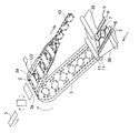
- FIG. 1 is a schematic perspective view of an example of a method for producing a pants-type disposable diaper using a laser-type joining device, which is applicable to the method for producing a pants-type disposable diaper of the present invention.
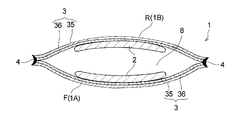
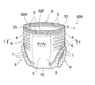
- FIG. 2 is a perspective view schematically showing a pants-type disposable diaper (pants-type disposable diaper outside the scope of the present invention) manufactured by carrying out the manufacturing method shown in FIG.
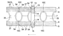
- FIG. 3 is a cross-sectional view schematically showing a cross section taken along line II of FIG.
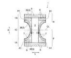
- FIG. 4 is a plan view schematically showing a developed and extended state of the diaper shown in FIG.
- FIG. 5 is a perspective view schematically showing a manufacturing process of the diaper continuous body shown in FIG. 1.
- FIG. 1 is a schematic perspective view of an example of a method for producing a pants-type disposable diaper using a laser-type joining device, which is applicable to the method for producing a pants-type disposable diaper of the present invention.
- FIG. 2 is a perspective view schematically showing a pants-type
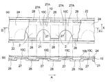
- FIG. 6 is a diagram schematically showing a state where the diaper continuous body is introduced into the laser-type bonding apparatus shown in FIG. 1 on a plane
- FIG. FIG. 6B is a cross-sectional view taken along the line II-II in FIG.
- FIGS. 7 (a) to 7 (c) show a side seal portion (seal edge portion) at the same time as the continuous diaper (band-like sheet laminate) is cut using the laser-type bonding apparatus shown in FIG. It is explanatory drawing explaining a mode that is formed.
- FIG. 8 is a cross-sectional view of one side seal portion and the vicinity thereof in a state where the waist opening of the diaper shown in FIG. 3 is expanded.
- FIG. 9 (a) and 9 (b) are respectively a joint part and a projecting part (side seal part visibility improving means) which are the main parts of the first embodiment of the pants-type disposable diaper of the present invention, and the vicinity thereof.
- 9A is a plan view in the natural state (contracted state) of the diaper of the first embodiment
- FIG. 9B is a state in which the waist opening of the diaper is expanded. It is a perspective view in (wearing state).
- FIG. 10 is a view corresponding to FIG. 2 of the second embodiment of the pants-type disposable diaper of the present invention (a perspective view schematically showing a state in which the diaper is viewed from the front body side).
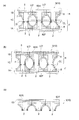
- 11 (a) to 11 (c) are explanatory diagrams of the manufacturing process of the diaper shown in FIG.
- FIG. 12 is a schematic front view of a mark (side seal portion visibility improving means) which is a main part of the third embodiment of the pants-type disposable diaper of the present invention and the vicinity thereof.
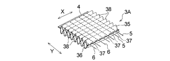
- FIG. 13 is a perspective view schematically showing a part of a composite elastic member used as an exterior body in the diaper shown in FIG.
- FIG. 14 is an explanatory diagram of the mark formation process shown in FIG.
- FIGS. 15 (a) to 15 (d) are views showing other examples of marks (side seal part visibility improving means) which are the main parts of the third embodiment of the pants-type disposable diaper of the present invention. It is an equivalent figure.
- the present invention relates to a pants-type disposable diaper with high visibility by visual observation of a side seal part and a method for manufacturing the same.
- One of the main features of the present invention includes an absorbent main body and an exterior body that is disposed on the non-skin contact surface side of the absorbent main body and fixes the absorbent main body.
- a pants-type disposable diaper in which the side edges and the left and right side edges of the back body are joined to form a pair of side seals, a waist opening, and a pair of leg openings, the visibility of the side seals is improved.
- the side seal part visibility improving means to be obtained is employed.
- the side seal portion visibility improving means is used in a manufacturing process of a pants-type disposable diaper, for example, a laser beam at a predetermined portion (a portion where the side seal portion is scheduled to be formed) of the diaper continuous body (band-shaped exterior body).
- the diaper continuous body strip-shaped exterior body
- the diaper continuous body is divided into individual pieces by irradiating, for example, and at the same time, the cut edges of the multiple exterior bodies produced by the division are fused together to form a pair of side seals This is particularly effective when forming the portion.
- Such a “side seal part obtained through a process in which the outer body is divided and fused at the same time” has low visibility when worn (in a worn state), and in particular, a diaper. From the viewpoint of tearing the side seal portion for removal, it is effective to employ a side seal portion visibility improving means to improve the visual visibility of the side seal portion when the diaper is worn.
- the side seal part is also a side seal part with low visual visibility even in the natural state (contracted state) of the diaper
- the side seal part is also used for determining the front and rear of the diaper and the right and left sides of the diaper. It is effective to employ a seal part visibility improving means to improve the visibility of the side seal part in the natural state (contracted state before wearing) of the diaper.
- a basic technique in which the side seal portion visibility improving means according to the present invention can be adopted will be described, and then the side seal portion visibility improving means will be described.
- a diaper 1 described later as a basic technique does not include the side seal portion visibility improving means according to the present invention, and is outside the scope of the present invention.
- FIG. 1 The outline of the manufacturing method of the underpants type disposable diaper using a laser type joining device applicable to the manufacturing method of the underpants type disposable diaper of the present invention is shown in FIG.
- a diaper 1 which is a manufacturing object of a manufacturing method using this laser type bonding apparatus is disposed on an absorbent main body 2 and a non-skin contact surface side of the absorbent main body 2.
- the left and right side edge portions B1 and B1 along the longitudinal direction X of the exterior body 3 in the (back side portion 1B) are joined to form a pair of side seal portions 4 and 4, a waist opening portion 8 and a pair of leg opening portions 9 and 9.
- the side seal portion 4 is formed by fusing with the edges of the plurality of exterior bodies 3 overlapping.
- the side seal portion has a width of 5 mm or less, 3 mm or less, or 2 mm or less.
- the diaper 1 has a longitudinal direction X corresponding to the wearer's front-rear direction and a lateral direction Y orthogonal to the wearer's front-rear direction in a developed and extended plan view as shown in FIG.
- the diaper 1 can be divided into a crotch part 1C arranged at the crotch part at the time of wearing, and an abdominal side part 1A and a back side part 1B located in the longitudinal direction X.
- the crotch portion 1 ⁇ / b> C is a region in which recessed portions for forming the leg openings 9 and 9 are formed at both left and right edges along the vertical direction X.
- the diaper 1 can be divided into a front body F and a back body R with a virtual center line CL that bisects the diaper 1 in the vertical direction X as a boundary.
- a skin contact surface is a surface turned to a wearer's skin side at the time of wear of a disposable diaper in a disposable diaper or its structural member (for example, absorbent main body 2), and a non-skin contact surface Is the surface of the disposable diaper or its component that is directed to the side opposite to the skin side (clothing side) when the disposable diaper is worn.
- the vertical direction X corresponds to the direction (longitudinal direction) along the long side of the absorbent main body 2 which is a disposable diaper or its constituent member
- the horizontal direction Y is the absorbent main body 2 which is a disposable diaper or its constituent member. Matches the width direction of.
- the absorbent main body 2 has a vertically long shape in one direction (longitudinal direction X), and a surface sheet (not shown) that forms a skin contact surface; A back sheet (not shown) that forms a non-skin contact surface, and a liquid-retaining absorbent (not shown) interposed between the two sheets. And has a long shape in the same direction.
- the absorbent main body 2 has its longitudinal direction aligned with the longitudinal direction X of the diaper 1 in the unfolded and extended state (the state shown in FIG. 4), and a known joining means (adhesive or the like) at the center of the outer package 3. It is joined by.
- the expanded and extended state means that the side seal portion is peeled off, the diaper is set in the expanded state, the elastic member of each part is expanded in the expanded diaper, and the design dimensions (the influence of the elastic member is eliminated at all). In this state, it is expanded until it becomes the same size as when expanded in a flat shape.
- the outer package 3 is arranged on the outer layer sheet 35 that forms the outer surface of the diaper 1 (non-skin contact surface of the outer package 3), and on the inner surface side of the outer layer sheet 35.
- An inner layer sheet 36 that forms the inner surface of 1 (the skin contact surface of the exterior body 3), and a plurality of thread-like or belt-like elastic members 5 fixed between the sheets 35, 36 by an adhesive (not shown). 6 and 7.
- the two sheets 35 and 36 are joined to each other at a predetermined site by an adhesive or heat seal (not shown).
- the exterior body 3 includes a resin material and is formed using the resin material as a main component.
- the resin material includes a heat-sealable synthetic resin such as polyethylene, polyethylene terephthalate, polypropylene, etc., and from a nonwoven fabric, a film, a laminate sheet of a nonwoven fabric and a film, etc.
- the nonwoven fabric include air-through nonwoven fabric, heat roll nonwoven fabric, spunlace nonwoven fabric, spunbond nonwoven fabric, and melt blown nonwoven fabric.
- the manufacturing method of the diaper 1 includes a main body fixing step of fixing the absorbent main body 2 to the belt-shaped outer package 3 (outer layer sheet 35, inner layer sheet 36), and a front body of the band-shaped outer package 3 to which the absorbent main body 2 is fixed.
- the side and the back body side are overlapped (one side edge side and the other side edge side along the longitudinal direction of the belt-shaped exterior body 3 are overlapped), and the portion where the side seal portion is to be formed in the overlapped exterior body 3 is pressurized.
- the cutting edges of the plurality of exterior bodies 3 in the pressurized state generated by the division are separated A side seal part forming step of forming the side seal part 4 by fusing. That is, the side seal portion 4 is formed by irradiating the laminated body of the belt-shaped exterior body 3 for the front body F and the belt-shaped exterior body 3 for the rearward appearance R to divide the multilayer body. Further, it is a cut edge portion of both the exterior bodies 3 and 3.
- the strip-shaped exterior body 3 (outer layer sheet 35, inner layer sheet 36) is folded in the width direction.
- the front body side and the back body side of the strip-shaped exterior body 3 to which the absorbent main body 2 is fixed are overlapped with each other, whereby “a precursor of a pants-type disposable diaper in which a side seal portion is not formed is unidirectional.
- a continuous diaper body 10 "is manufactured separately.
- the diaper continuous body 10 strip-shaped exterior body 3 is divided (melted) individually by irradiation with laser light 30 as shown in FIG.
- a plurality of exterior bodies 3 (outer layer sheet 35, inner layer sheet 36) in a pressurized state generated by the division are fused to each other, and the exterior body 3 having a pair of side seal portions 4 and 4 is provided.
- the pants-type disposable diaper 1 to be manufactured is continuously manufactured.
- the waist elastic member 5 forming the waist gather, the waist elastic member 6 forming the waist gather, and the leg elastic member 7 forming the leg gather are extended to a predetermined extension rate. A plurality of each is distributed.
- the leg elastic member 7 is arranged while forming a predetermined leg-circumferential pattern via a known swing guide (not shown) that reciprocates perpendicular to the sheet flow direction.
- an adhesive coating machine (A hot-melt type adhesive is applied by (not shown).
- a hot melt adhesive is intermittently applied to the waist elastic member 5 and the waist elastic member 6 by an adhesive application machine (not shown) before being disposed between the sheets 35 and 36. May be.
- a belt-shaped outer layer sheet 35 and a belt-shaped outer layer sheet 5 in which a waist elastic member 5, a waistline elastic member 6 and a leg elastic member 7 are sandwiched in an expanded state.
- a band-shaped exterior body 3 is formed in which a plurality of elastic members 5, 6, and 7 are arranged in an expanded state between the band-shaped sheets 35 and 36.
- a plurality of joint portions for joining the belt-like outer layer sheet 35 and the belt-like inner layer sheet 36 between the two adjacent waistline elastic members 6 and 6; It forms using joining means (not shown), such as a convex roll and an anvil roll corresponding to this.
- joining means such as a convex roll and an anvil roll corresponding to this.
- a plurality of waistline elastic members 6 and a plurality of leg elastic members are used by using elastic member pre-cut means (not shown) so as to correspond to positions where the absorbent main body 2 described later is disposed. 7 is pressed and divided into a plurality of pieces so that the contraction function is not expressed.
- the elastic member precut means include an elastic member dividing portion used in the method for manufacturing a composite elastic member described in JP-A-2002-253605.
- an adhesive such as a hot melt adhesive is applied in advance to the absorbent main body 2 manufactured in a separate process, and the absorbent main body 2 is rotated 90 degrees to form a belt-shaped outer package. 3 is intermittently supplied and fixed on the inner layer sheet 36 constituting 3 (main body fixing step).
- the adhesive for fixing the absorbent main body may be applied in advance to the position where the absorbent main body 2 is to be arranged in the inner layer sheet 36 instead of the absorbent main body 2.
- a leg hole LO ′ is formed inside the annular portion surrounded by the leg elastic member 7 in the strip-shaped exterior body 3 in which the absorbent main body 2 is disposed.
- This leg hole forming step can be carried out by using a technique similar to that in a conventional method for manufacturing this type of article, such as a rotary cutter and a laser cutter.
- the leg hole is formed after the absorbent main body 2 is arranged on the belt-shaped outer package 3, but the leg hole may be formed before the absorbent main body 2 is arranged.
- the strip-shaped exterior body 3 is folded in the width direction (a direction perpendicular to the conveying direction of the exterior body 3). More specifically, as shown in FIG. 5, both side portions 3 a, 3 a along the transport direction of the strip-shaped exterior body 3 are arranged at both longitudinal ends of the absorbent main body 2 (the longitudinal direction of the absorbent main body 2 shown in FIG. 4). After folding back so as to cover both ends in the direction X and fixing both ends in the longitudinal direction of the absorbent main body 2, the exterior body 3 is folded in the width direction together with the absorbent main body 2 (polymerization pressure step). In this way, the diaper continuous body 10 is obtained.
- the diaper continuous body 10 separately manufactured in this manner is irradiated with laser light using a laser bonding apparatus 20 to form a pair of side seal portions 4 and 4 (side seals).
- the underpants type disposable diaper 1 which comprises the exterior body 3 which has a pair of this side seal part 4 is manufactured continuously.
- the laser bonding apparatus 20 includes, as shown in FIG. 1, a hollow cylindrical roll 23 having a cylindrical support member 21 that is rotationally driven in the direction of arrow A, and an endless shape. And a belt type pressure device 26 including a pressure belt 24 (pressing member).
- the laser-type bonding apparatus 20 has an interval adjustment mechanism (not shown) that can increase or decrease the interval between the support member 21 (the peripheral surface portion of the cylindrical roll 23) and the pressure belt 24. By adjusting the interval, the support member The pressure applied to the diaper continuous body 10 can be appropriately adjusted by the pressure belt 21 and the pressure belt 24.
- the support member 21 forms a peripheral surface portion (contact portion with the workpiece) of the cylindrical roll 23, and is sandwiched between a pair of annular frame bodies 22, 22 forming left and right side edges of the cylindrical roll 23. It is fixed.
- the support member 21 is composed of a single annular member having the same length as the circumferential length of the annular frame 22, and is a metal material such as iron, aluminum, stainless steel, copper, or a material having heat resistance such as ceramics. Consists of.
- the support member 21 has a light passage portion through which laser light can pass. As shown in FIGS. 1 and 6, the support member 21 has a slit-shaped opening 27 that penetrates the support member 21 in the thickness direction as a light passage portion.
- the opening 27 has a rectangular shape in plan view, and its longitudinal direction is the width direction of the support member 21 (the direction indicated by the symbol X in FIG. 6A. The direction parallel to the rotation axis of the cylindrical roll 23).
- a plurality of cylindrical support members 21 are formed at predetermined intervals in the circumferential direction. The support member 21 allows the laser light to pass through the opening 27, but does not allow the laser light to pass (transmit) at portions other than the opening 27.
- the method of forming the opening 27 in the support member 21 includes 1) a method of drilling the opening 27 in a predetermined portion of the support member 21 by etching, punching, laser processing, or the like. A method of using a plurality of curved rectangular members in place of one annular member, and arranging the plurality of members between the pair of frame bodies 22 and 22 with a predetermined interval in the circumferential direction of the frame body 22 Is mentioned. In the method 2) described above, the interval between two adjacent members forms a slit-shaped opening 27.
- symbol 27A in FIG. 6A is employ
- the support member 21 has a recess 28 on its outer surface (contact surface with the workpiece).
- a plurality of recesses 28 are formed at predetermined intervals in the circumferential direction of the cylindrical support member 21, and a slit-shaped opening 27 is formed in a region (convex part) located between two adjacent recesses 28, 28. Is formed.
- the opening 27 is formed in the center in the circumferential direction of the cylindrical support member 21 in the convex portion.
- the thickness of the diaper continuous body 10 is not uniform because the concave portion 28 is formed on the outer surface of the support member 21, a relatively thick portion (for example, an absorbent main body) in the diaper continuous body 10. It is possible to introduce the diaper continuous body 10 onto the outer surface of the support member 21 so that the second arrangement region 2 is within the recess 28. Then, when the diaper continuous body 10 is introduced onto the support member 21 in such a manner, as shown in FIG. 6B, the contact surface (the other surface) of the diaper continuous body 10 with the pressure belt 24 (pressing member).
- the belt-type pressure device 26 includes an endless pressure belt 24 (pressing member) and three rolls 25a, 25b, and 25c that rotate while the pressure belt 24 is stretched.
- the rolls 25a, 25b, and 25c may be drive rolls or driven rolls that rotate with the cylindrical roll 23.
- the pressure belt 24 moves at the same speed as the cylindrical roll 23 (supporting member 21) with one or more of the rolls 25 a, 25 b, 25 c as a rotational drive or with the cylindrical roll 23.
- the support member 21 and the pressure belt 24 are preferably maintained in a predetermined temperature range by air cooling, water cooling, or the like.
- a metal or resin belt having heat resistance capable of withstanding the heat generated during processing can be used, for example, a metal material such as iron, aluminum, stainless steel, or the like. Can be used.
- a belt that does not have the transparency of the laser beam irradiated on the workpiece (diaper continuous body 10) is usually used, but a belt having the transparency may be used. it can.
- an irradiation head 31 that irradiates a laser beam 30 toward the support member 21 that forms the peripheral surface portion of the cylindrical roll 23 is provided in the hollow portion of the hollow cylindrical roll 23 (support member 21). It has been.
- the irradiation head 31 is a galvano scanner that freely scans the laser beam 30 (an apparatus having a mirror on the motor shaft), and the laser beam 30 is in a direction parallel to the rotation axis of the cylindrical roll 23 (reference numeral in FIG. 6A).
- a mechanism for making the spot diameter of the light 30 constant is provided.
- the irradiation head 31 does not have a function (light source) for generating the laser light 30, and the laser light 30 is generated by a light source (not shown) arranged outside the cylindrical roll 23.
- the irradiation head 31 is reached through an optical path (not shown) connecting the two.
- the laser irradiation mechanism has such a configuration, so that the irradiation point of the laser light 30 is the circumferential direction of the cylindrical roll 23 and a direction orthogonal to the circumferential direction (a direction indicated by a symbol X in FIG. 6A). It can be arbitrarily moved in both directions of a direction parallel to the rotation axis of the roll 23).
- symbol X in FIG. 6 is the vertical direction X of the diaper 1 (absorbent main body 2) in FIG. Is in the same direction.
- the diaper continuous body 10 includes a support member 21 that forms a peripheral surface portion of a cylindrical roll 23 that is rotationally driven in the direction of arrow A in a state where a predetermined tension is applied by a guide roll (not shown). After being transported by a predetermined distance in the circumferential direction by rotation of the cylindrical roll 23 so as to be wound around the support member 21, it is separated from the support member 21 by an unillustrated lead roll, nip roll or the like. . As described above, the diaper continuous body 10 is wound around the support member 21 forming the peripheral surface portion of the cylindrical roll 23 with a predetermined tension and is conveyed so as to be in pressure contact with the pressure belt 24.
- the portion sandwiched between the support member 21 and the pressure belt 24 and the vicinity thereof are in a state of being pressurized (compressed) in the thickness direction from before being divided by the laser light irradiation.
- the diaper continuous body 10 contains a nonwoven fabric, the diaper continuous body 10 can be more efficiently compressed, and as a result, the diaper continuous body 10 being compressed is irradiated with laser light.
- this it becomes possible to fuse the cut edges of the plurality of sheets (exterior body 3) constituting the divided portion more reliably, and the side seal portion 4 can be fused. The strength is further improved.
- the rotation angle of the support member 21 (cylindrical roll 23) from when the diaper continuous body 10 is introduced onto the support member 21 to when the diaper continuous body 10 leaves the diaper continuous body 10 can be, for example, 90 degrees or more and 270 degrees or less. Is 120 degrees or more and 270 degrees or less.
- the range of the angle (pressure contact angle) at which the diaper continuous body 10 is pressed against the support member 21 by the pressure belt 24 (pressing member) is the entire circumference of the cylindrical support member 21 (cylindrical roll 23). When the pressure contact is 360 degrees, it is preferably 90 degrees or more and 270 degrees or less, and more preferably 120 degrees or more and 270 degrees or less.
- a slit-like opening through which the continuous surface of the diaper 10 is continuously conveyed and the one surface 10 a forms the peripheral surface portion of the cylindrical roll 23 and the laser beam 30 can pass through.
- the diaper continuum 10 (of the side seal portion 4) having a portion 27 (light passage portion) and brought into contact with the outer surface of the support member 21 and brought into a pressurized state by the support member 21 and the pressure belt 24 (pressing member).
- the diaper continuous body 10 is divided by irradiating the laser beam 30 from the support member 21 side through the opening 27 with respect to the planned formation site), and at the same time, the pressurized state is generated by the division.
- the side seal portions 4 are formed by fusing the cut edges of the plurality of sheets (the outer package 3) (side seal portion forming step).
- the other surface 10 b of the diaper continuous body 10 that is in contact with the support member 21 (the side opposite to the one surface 10 a that is a contact surface with the support member 21).
- the pressing belt 24 pressing member
- the diaper continuous body 10 in this state is irradiated with the laser beam 30 from the support member 21 side through the slit-shaped opening 27,
- the diaper 1 which comprises the exterior body 3 which has a pair of side seal parts 4 and 4 is manufactured continuously.
- the irradiation of the laser beam 30 was performed on the diaper continuum 10 in a pressurized state (compressed state) by being sandwiched between the support member 21 and the pressure belt 24 by the irradiation. It is preferable from the viewpoint of improving the fusion strength of the side seal portion 4 by reliably fusing the cut edges of the plurality of sheets (the outer package 3).
- FIG. 7 is a diagram for explaining how the side seal portion 4 (seal edge) is formed at the same time as the diaper continuous body 10 (band-shaped sheet laminate) is divided using the laser bonding apparatus 20.
- 7 (a) schematically shows a portion 10C (part where the side seal portion 4 is to be formed) scheduled to be divided by the laser beam 30 of the diaper continuous body 10 and its vicinity.
- the diaper continuous part 10C of the diaper continuous body 10 in the illustrated embodiment is the center in the longitudinal direction (conveying direction A) in the region where the absorbent main body 2 of the diaper continuous body 10 is not disposed. It is. 10 C of such parting plan parts are the opening edge part of the waist opening part 8 (refer FIG.
- the 8 layer structure part on which 8 sheets were piled up, and other parts are 4 sheets. It is a four-layer structure part that is superimposed.
- the four-layer structure portion includes two sheets (an outer layer sheet 35 and an inner layer sheet 36) constituting one exterior body 3 in the ventral side part 1A, and a back side part 1B. It consists of the same two sheets 35 and 36 constituting one exterior body 3, and these four sheets are laminated.
- the eight-layer structure portion is folded so that both side portions 3a and 3a of the strip-shaped outer package 3 cover both longitudinal ends of the absorbent main body 2 when the diaper continuous body 10 is manufactured ( (See FIGS.
- any one or both of the sheets (inner layer sheet 36) absorb the laser beam 30 and generate heat.
- all of the four sheets 35, 36 constituting the parting planned portion 10 ⁇ / b> C are sheets (nonwoven fabrics) that absorb the laser beam 30 and generate heat.
- the two sheets of the outer layer sheet 35 and the inner layer sheet 36 that overlap each other in the vicinity of the portion 10C to be divided may be joined by an adhesive or the like before the irradiation with the laser beam 30, or may be joined at all. It is not necessary.
- the diaper continuous body 10 has one surface 10 a abutting against the support member 21, and a parting planned portion 10 ⁇ / b> C (part where the side seal portion 4 is to be formed) is on the slit-shaped opening 27.
- the pressure belt 24 pressing member
- the pressure belt 24 is pressed against the other surface 10b so that it is conveyed in the direction of the arrow A while being introduced onto the support member 21 that rotates in the direction of the arrow A so as to be positioned in the direction of the thickness A.
- Pressure compression
- the laser beam 30 is irradiated through the opening part 27 from the supporting member 21 side with respect to the parting part 10C to be divided in such a conveyance and pressurization state.
- the irradiation point of the laser beam 30 is configured to be arbitrarily movable in the circumferential direction of the cylindrical roll 23 and is set so as to follow the movement of the opening 27 along the circumferential direction. Therefore, the laser beam 30 is continuously irradiated for a certain period of time to the parting planned portion 10C located on the opening 27 during the conveyance.
- the forming materials (fibers, etc.) of the sheets 35 and 36 existing in the parting portion 10C are vaporized by the heat generated by the direct irradiation of the laser light 30 and disappear.
- the forming material existing in the vicinity of the parting portion 10 ⁇ / b> C is indirectly heated by the laser beam 30 and melted.
- the parting plan part 10C of a four-layer structure is melted, and in a form in which a single sheet sheet laminate (diaper precursor) is cut from the diaper continuous body 10,
- the cut edges of the four sheets 35 and 36 in the sheet laminate of the single sheet produced by the division and the diaper continuous body 10 that has been cut out The cut edges of the four sheets 35 and 36 are fused together.
- Each of these cut edges is pressed (compressed) by being sandwiched between the support member 21 and the pressure belt 24 from before the formation (before the diaper continuous body 10 is divided by irradiation with the laser beam 30). ).
- the strip-shaped exterior body 3 is divided by the single laser light irradiation, and the exterior body 3 in the two pressurized states generated by the division is thus obtained.
- the fusion and separation are the same with approximately half the laser output compared to the method of fusing the two fusion places with two laser irradiations. It can be carried out in a process, and the diaper 1 can be manufactured efficiently.
- fusion and division can be performed in the same process, a non-sealed edge in which the cut edges of the sheet (exterior body) are not fused is not generated, and thus there is an effect of reducing material.
- the cut edges of the sheets 35 and 36 are heated and melted during the irradiation of the laser beam 30 and immediately after the end of the irradiation, but are separated from the diaper continuous body 10 by the irradiation of the laser beam 30.
- Each of the leaf diaper precursor and the diaper continuous body 10 is quickly cooled and solidified by the outside air after the irradiation is completed while the pressure state of the support member 21 and the pressure belt 24 is maintained, and the cutting is performed.
- the edge forming material becomes the fused portion 40 which is fused and integrated.
- the cutting edge portions of the sheets 35 and 36 may be forcibly cooled by using known cooling means such as a suction device and an exhaust device to promote the formation of the fused portion 40.
- the laser beam 30 seems to hit another opening 27 adjacent to the irradiation direction in the direction opposite to the conveyance direction A. And is irradiated to another parting planned portion 10C located thereabove through the other opening 27.
- another part 10C to be divided is divided and fused in the same manner as described above, and the other side seal part 4 (fused part 40) that forms a pair with the previously formed side seal part 4 is formed.
- the pants-type disposable diaper 1 including the exterior body 3 having the pair of side seal portions 4 and 4 is continuously manufactured.
- a side seal part 4 can be cited.
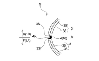
- the direction (shown in FIG. 4) orthogonal to the direction in which the side seal portion 4 extends (the direction indicated by X in FIG. 1; the same direction as the longitudinal direction X of the diaper 1 shown in FIG. 4).
- the outer edge 4a of the side seal portion 4 generated by the division forms a convex arc shape inward of the exterior body 3, and includes the outer edge 4a.
- the fusion part 40 between the four sheets 35 and 36 constituting the exterior body 3 is formed inside the exterior body 3 more than that, and the fusion part 40 is formed in the thickness direction of the exterior body 3 (
- the central portion in the vertical direction in FIG. 7C is wider than both end portions (upper end portion and lower end portion). That is, the width of the fused part 40 gradually increases toward the center in the thickness direction in the cross-sectional view along the lateral direction Y (direction perpendicular to the laser beam dividing direction) of the diaper 1. It is formed in a so-called crescent shape or half-moon shape (the fused portion 40 shown in FIG. 7C is a crescent shape).
- the side seal portion 4 is harder and softer than other parts of the diaper 1 due to the presence of the fused portion 40 formed by melting and solidifying the sheet forming material, and causes the feeling of wearing the diaper 1 to be reduced.
- the fusion part 40 is formed in a crescent shape or a half moon shape in a cross-sectional view in the width direction of the diaper 1 as described above, the fusion part in the conventional side seal part (for example, in Patent Document 1) Compared to the case where it is formed in a rectangular shape in the same sectional view as shown in FIG. 1 (part indicated by reference numeral 10), the corner 3S of the side edge portion of the exterior body 3 constituting the side seal portion 4 is formed.
- the wearing feeling of the diaper is improved as compared with the conventional product.
- the central portion in the thickness direction of the side edge of the exterior body 3 (the corner 3S on the one surface side of the exterior body 3 and the 3S on the other surface side, which is a part that greatly affects the fusion strength of the side seal portion 4) Since a sufficient amount of the fused portion 40 exists in the portion sandwiched between the side seal portion 4 and the side seal portion 4, the side seal portion 4 has a practically sufficient fusion strength. Inconveniences such as tearing are unlikely to occur.
- the outer edge 4a of the side seal portion 4 has a convex arc shape toward the inside of the exterior body 3, so that the waist opening 8 is widened when the diaper 1 is worn as shown in FIG.
- the corner 3S of the side edge of the exterior body 3 on the abdominal side 1A side and the corner 3S of the side edge of the exterior body 3 on the back side 1B side approach each other, and between the corners 3S and 3S. Therefore, the fusion portion 40 positioned between the corner portions 3S and 3S is moved by the both corner portions 3S and 3S located on the outer side of the diaper 1 with respect to the fusion portion 40 and close to each other. It is difficult to touch and is difficult to visually recognize from the outside, whereby not only the feeling of wearing the diaper 1 but also the appearance is improved.
- the diaper continuum 10 [scheduled part 10C (scheduled part for forming the side seal portion 4)] made of a nonwoven fabric is a metal material during and immediately after irradiation of the laser beam 30 on the parted part 10C of the diaper continuous body 10 This is probably because the support member 21 and the pressing member 24 are interposed between the support member 21 and the pressing member 24.
- the metal material that is the main forming material of the support member 21 and the pressing member 24 that sandwich the diaper continuous body 10 (the outer layer sheet 35 and the inner layer sheet 36) from above and below is the nonwoven fabric that is the main forming material of the sheets 35 and 36. Since the heat conductivity is higher than that of the laser beam 30, the heat generated in the sheets 35 and 36 by the irradiation of the laser beam 30 is easily absorbed by the support member 21 or the pressing member 24 in contact with the sheets 35 and 36.
- the corner portion 3S of the side edge portion of the exterior body 3 constituting the side seal portion 4 formed by dividing the diaper continuous body 10 by irradiation with light 30 has a higher thermal conductivity than the corner portion 3S.
- the heat generated in the corner portion 3S is quickly absorbed by both the members 21 and 24.
- the corner portion 3S Hardly become a hot extent that made, therefore, the proportion of fused portion 40 is very small site.
- the central portion in the thickness direction of the side edge portion of the exterior body 3 (the portion sandwiched between the corner 3S on the one surface side of the exterior body 3 and the 3S on the other surface side) has both members 21 with high thermal conductivity. 24, the heat generated in the central portion by the irradiation of the laser beam 30 stays in the central portion and melts the central portion. As a result, many fusion portions 40 are unevenly distributed in the central portion. become.
- the support member 21 and the pressing member 24 are made of iron
- At least a part of the plurality of sheets (particularly the outer layer sheet 35 forming the outer surface of the diaper 1) made of a metal material such as aluminum, stainless steel, copper, or ceramics and constituting the outer package 3 is a resin.
- the material is included, and specifically, for example, it is preferably made of a nonwoven fabric.
- the resin material is contained in all the sheets of the plurality of sheets 35.
- a nonwoven fabric what is normally used in the said technical field can be especially used without a restriction
- the wavelength of the laser beam irradiated to the diaper continuous body 10 is absorbed by the sheets (outer layer sheet 35 and inner layer sheet 36) constituting the outer package 3 and generates heat.
- the laser beam is used.
- the “sheet constituting the exterior body” is not limited to the sheet (for example, the outer layer sheet 35 in the above-described embodiment) constituting one surface of the exterior body (the contact surface with the support member 21). Any sheet may be used as long as the sheet is configured.
- the laser light applied to the exterior body is a wavelength that is absorbed by the sheet and generates heat for the individual sheets constituting the exterior body depends on the material of the sheet and the wavelength of the laser light to be used. It depends on the relationship.
- the laser beam may be CO 2 laser, YAG It is preferable to use a laser, an LD laser (semiconductor laser), a YVO4 laser, a fiber laser, or the like.
- seat which comprises an exterior body contains polyethylene, a polyethylene terephthalate, a polypropylene etc. as a synthetic resin, as a wavelength which can be absorbed by this sheet
- the spot diameter of laser light, laser output, and the like can be appropriately selected in consideration of the material and thickness of the sheet constituting the exterior body.
- the diaper 1 which comprises is excellent in the softness
- the side seal portion 4 is more outward than the peripheral portion of the side seal portion 4 at least on the outer surface and inner surface of the diaper 1 when worn. Since the state of the outer surface and the inner surface of the diaper 1 does not substantially change across the side seal portion 4, it is difficult to visually recognize the side seal portion 4 from the outside, and the visibility of the side seal portion 4 is visually recognized. Low.
- the diaper 1 is provided with means for improving the side seal part visibility.
- the side seal portion visibility improving means is preferably located in the vicinity of the side seal portion 4 and at the opening end of the waist opening 8 or in the vicinity thereof, as in the first, second and third embodiments described later. ing.
- the side seal portion visibility improving means is the above-described method for manufacturing a pants-type disposable diaper having a main body fixing step, a polymerization pressurizing step and a side seal portion forming step, after the main body fixing step is completed. It is given to the exterior body 3 before the end of the part forming step.
- the side seal part visibility improving means according to the present invention, the pants-type disposable diaper according to the present invention and the method for manufacturing the same will be described with reference to the drawings based on preferred embodiments thereof.
- components different from the [Basic Technology] will be mainly described, and the same components will be denoted by the same reference numerals, and description thereof will be omitted. For the components that are not particularly described, the description of [Basic Technology] is appropriately applied.
- FIG. 9 shows a joint 51 and a protrusion 52 (side seal part visibility improving means) that are the main parts of the first embodiment of the pant-type disposable diaper of the present invention (pants-type disposable diaper 50A) and their vicinity. It is shown.
- the diaper 50A of the first embodiment is a diaper 1 except that the diaper 1 described above is provided with a protruding portion 52 as a side seal portion visibility improving means and a joint portion 51 necessary to form the protruding portion 52. It is configured in the same way.
- the projecting portion 52 is located at a portion of each of the pair of side seal portions 4 and 4 that forms the opening end portion of the waist opening portion 8, and is formed at a portion surrounded by a dotted circle in the diaper 1 shown in FIG. ing.
- the diaper 50A of the first embodiment will be further described.
- the front body F in the vicinity of the side seal portion 4 and at the opening end 81 of the waist opening 8 or in the vicinity thereof.
- a protruding portion 52 is formed so as to protrude outward from the peripheral portion (see FIG. 9B), and this protruding portion 52 functions as a side seal portion visibility improving means. That is, in the diaper 50 ⁇ / b> A, the visibility of the side seal portion 4 is improved by the presence of the protruding portion 52.
- the joint portions 51 are formed symmetrically one by one on both sides (the front body F side and the back body R side) with the side seal portion 4 interposed therebetween.
- the joining portion 51 uses the same laser light before and after the irradiation of the laser light for dividing the formation planned site of the side seal portion 4 of the exterior body 3 in the pressurized state in the side seal portion forming step.
- the outer body 3 is formed on the outer body 3 and has a predetermined planar view shape such as a circular shape in the pressurized state of the outer body 3 (diaper continuous body 10) when the laser beam is irradiated.
- 50A (the exterior body 3 in the front body F and the exterior body 3 in each of the back body R) includes a through-hole penetrating in the thickness direction.
- the joint portion 51 In the natural state of the diaper 1 or in a normal use state, the joint portion 51 is in a state that is difficult to visually recognize due to shrinkage of the portion where the joint portion 51 is formed (in FIG. 9A). Although the joint portion 51 is illustrated from the viewpoint of ease of explanation, it is not always visually visible in this manner.
- the joint portion 51 is mainly formed to form the protruding portion 52, and the joint portion 51 itself may not function as the side seal portion visibility improving means, and the shape of the joint portion 51 Alternatively, the protruding portion 52 may be made more conspicuous by adjusting the size appropriately so that the joint portion 51 can be visually recognized, and the visibility of the side seal portion 4 can be improved.
- the division of the exterior body 3 and the formation of the joint portion 51 are absorbed by the sheets (the outer layer sheet 35 and the inner layer sheet 36) constituting the exterior body 3, and the sheet is heated. This is performed by irradiating the exterior body 3 with a laser beam having a wavelength. More specifically, as shown in FIG. 6 (a), a bonding portion through which the laser beam 30 can pass is formed at a predetermined position (in the vicinity of the slit-shaped opening 27) of the support member 21 in the laser bonding apparatus 20.
- the light transmitting portion 27A is previously drilled, and the laser beam 30 is irradiated from the support member 21 side through the slit-shaped opening 27 to the pressurized exterior body 3 (diaper continuous body 10). Before or after irradiation, the laser beam 30 is irradiated from the support member 21 side through the bonding portion forming light transmitting portion 27A. Thereby, the forming materials (fibers and the like) of the sheets 35 and 36 existing in the portion corresponding to the light transmitting portion 27 ⁇ / b> A in the exterior body 3 are melted or vaporized by the direct heat of the laser light 30 and disappear.
- the forming material of the sheets 35 and 36 When the forming material of the sheets 35 and 36 is melted without disappearing due to heat generated by the direct irradiation of the laser beam 30, the melted portion becomes the joint portion 51, and the front body F is formed at the joint portion 51 under the pressurized state.
- the exterior body 3 and the exterior body 3 in the back body R are joined.
- the disappeared portions of the exterior body 3 in the front body F and the exterior body 3 in the back body R are in the thickness direction.
- the forming material existing at the opening edge of the through hole is melted by being indirectly heated by the laser beam 30 and the melted portion (opening edge of the through hole) is joined.
- the exterior body 3 in the front body F and the exterior body 3 in the back body R are joined at the joint 51 under the pressurized state.
- the plan view shape of the light transmitting portion 27A is not limited to a circular shape as shown in FIG. 6, and can be set to various shapes such as a rectangular shape.
- the joint 51 is formed in the diaper 50A in the vicinity of the side seal part 4 and in the opening end 81 of the waist opening 8 or in the vicinity thereof, and the exterior body 3 and the back body in the front body F at the joint 51.
- the portion of the exterior body 3 (outer layer sheet 35, inner layer sheet 36) located outside the joint portion 51 (side seal portion 4 side) is when the diaper 1 is worn.
- the protrusion 52 is not along the wearer's body, and thus can be visually recognized.
- the diaper 50A in the worn state is worn by the wearer due to the presence of the protruding portion 52 located in the vicinity thereof.
- the side seal part 4 can be quickly confirmed, and thereafter the diaper 50A can be torn into the front body F and the back body R at the side seal part 4 as usual. The later diaper can be quickly removed from the body.
- the separation distance between the joint portion 51 and the side seal portion 4 is preferably 2 mm or more, more preferably 3 mm or more, and preferably It is 20 mm or less, More preferably, it is 15 mm or less, More specifically, Preferably it is 2 mm or more and 20 mm or less, More preferably, it is 3 mm or more and 15 mm or less. Further, from the same viewpoint, the separation distance between the joint portion 51 and the edge 82 of the opening end 81 of the waist opening 8 positioned immediately above is preferably 1 mm or more, more preferably 3 mm or more, and preferably 20 mm.
- the “separation distance” is measured for the diaper in the expanded and extended state, and the “expanded and extended state” is as described above.
- the outer body is divided and the joint is formed in the side seal portion forming step by melting the outer body using a heat source, and when the diaper is worn by forming the joint. It is only necessary to allow the protrusions to be formed in the case, and the melting of the exterior body using the heat source is not limited to the irradiation of the laser beam to the exterior body as described above. It can also be carried out by thermocompression bonding of the exterior body using a heat roll device or the like, or applying ultrasonic vibration to the exterior body using a known ultrasonic vibration device or the like.
- FIG. 10 shows a second embodiment of the pant-type disposable diaper of the present invention (pants-type disposable diaper 50B).
- the diaper 50B of the second embodiment is configured in the same manner as the diaper 1 except that the diaper 1 described above is provided with a step 53 as a side seal portion visibility improving means.
- the diaper 50B of the second embodiment will be further described.
- the edge 82F and the back body of the exterior body 3 in the front body F that form the opening end of the waist opening 8 are formed.
- the edge 82R of the exterior body 3 in R is not displaced in the same position in the vertical direction of the diaper 1 (vertical direction in FIG. 10), and both end edges 82F due to the deviation are located above the side seal portion 4.
- the visibility of the side seal portion 4 is improved due to the presence of the step 53.
- the end edge 82R of the back body R is positioned above the end edge 82F of the front body F.
- the end edge 82F of the front body F is the back body R of the back body R. It may be located above the end edge 82R.
- the side seal portion visibility improving means (step 53) is provided before the side seal portion forming step. ).
- the front body side and the back body side of the exterior body 3 are overlapped in the polymerization pressurization step, that is, as shown in FIG. 11A or FIG. 11 (c) by intentionally shifting the two end edges 82F and 82R along the longitudinal direction of the outer package 3 (left and right direction in FIG. 11) without matching each other when folded in the width direction.
- the step 53 is formed.
- This shift amount corresponds to the height t of the step 53 (see FIG. 10).
- the following method a shown in FIG. 11A and FIG. The following method b shown is mentioned, and any of them may be used.
- Method a When the length in the vertical direction X is equal between the front body F and the back body R with respect to the virtual center line CL that bisects the diaper in the vertical direction X, the virtual center line CL is not folded. In addition, another straight line parallel to the virtual center line CL is used as a folding line Q (see FIG. 11A).
- FIG. 11 (a) from the viewpoint of positioning the end edge 82R of the back body R above the end edge 82F of the front body F as shown in FIG. Is also shifted to the front body F (ventral side 1A) side. That is, in the embodiment shown in FIG.
- Method b A method in which the length in the longitudinal direction X is different between the ventral portion 1A and the dorsal portion 1B, and the virtual center line CL ′ that bisects the crotch portion 1C in the longitudinal direction X is a folding line (FIG. 11 (b)). That is, in the embodiment shown in FIG. 11 (b), the intentional displacement of the two end edges 82F and 82R along the longitudinal direction of the strip-shaped exterior body 3 (diaper continuous body 10) is the same as that of the ventral portion 1A in the diaper 50B.
- the length of the longitudinal direction X is different from that of the dorsal side 1B, and the belt-shaped exterior body 3 is folded using a virtual center line CL ′ that bisects the crotch part 1C of the diaper 50B in the vertical direction X as a folding line. This is done by folding along a curved line (virtual center line CL ′).
- a virtual center line CL ′ that bisects the crotch part 1C of the diaper 50B in the vertical direction X as a folding line.
- the length in the vertical direction X is shortened.
- the virtual center line CL ′ that bisects the crotch part 1 ⁇ / b> C in the vertical direction X coincides with the virtual center line that bisects the diaper 1 in the vertical direction X.
- the height of the step 53 is preferably 2 mm or more, more preferably 3 mm or more, and preferably 20 mm or less, from the viewpoint of the balance between the improvement of the visibility of the side seal part 4 and the shape maintenance as the diaper 1. More preferably, it is 15 mm or less, More specifically, Preferably it is 2 mm or more and 20 mm or less, More preferably, it is 3 mm or more and 15 mm or less.
- the “height of the step” here is measured for a diaper in a natural state.
- FIG. 12 shows a mark 54 (side seal portion visibility improving means) which is a main part of the third embodiment of the pant-type disposable diaper of the present invention (pants-type disposable diaper 50C) and the vicinity thereof.
- the diaper 50C of the third embodiment is configured in the same manner as the diaper 1 except that the diaper 1 described above is provided with a mark 54 as a side seal portion visibility improving means.
- the diaper 50C of the third embodiment will be further described.
- the outer surface (non-skin contact surface) of the exterior body 3 in the front body F (abdominal side portion 1A) and a side seal are provided.
- a mark 54 that can be visually recognized is formed in the vicinity of the portion 4 or on the outer surface (non-skin contact surface) of the exterior body 3 in the back body R (back side portion 1B) and in the vicinity of the side seal portion 4.
- the mark 54 functions as a side seal portion visibility improving means. That is, in the diaper 50 ⁇ / b> C, the visibility of the side seal portion 4 is improved due to the presence of the mark 54.
- the mark 54 is located on both sides (the front body F side and the back body R) with the side seal portion 4 sandwiched between the side seal portion 4 and the open end 81 of the waist opening 8 or the vicinity thereof. Are formed symmetrically one by one on the side) and have a heart shape in plan view.
- the distance between the mark 54 and the side seal portion 4 is preferably 1 mm or more, more preferably 5 mm or more, and preferably 30 mm.
- it is more preferably 25 mm or less, more specifically, preferably 1 mm or more and 30 mm or less, more preferably 5 mm or more and 25 mm or less.
- the distance between the mark 54 and the edge 82 of the opening end 81 of the waist opening 8 positioned immediately above is preferably 1 mm or more, more preferably 5 mm or more, and preferably 60 mm or less. More preferably, it is 50 mm or less, more specifically, preferably 1 mm or more and 60 mm or less, more preferably 5 mm or more and 50 mm or less.
- the “separation distance” is measured for the diaper in the expanded and extended state, and the “expanded and extended state” is as described above.
- the side seal portion visibility improving means is provided before the side seal portion forming step. ).
- the mark 54 is formed by embossing or printing.
- the embossing method and the printing method are not particularly limited, and known methods can be selected as appropriate.
- the composite elastic member 3A shown in FIG. 13 is used as the exterior body 3, and as shown in FIG. 14, the mark 54 is formed in the embossing used in the manufacture of the composite elastic member 3A.
- the composite elastic member 3A has the following configurations 1 to 3.
- As the composite stretchable member 3A for example, a composite stretchable member described in Japanese Patent Application Laid-Open No. 2009-118986 according to the previous application of the present applicant can be applied.
- the composite elastic member 3A having the following configurations 1 to 3 can be used without limitation as the exterior body 3 of the first embodiment and the second embodiment.
- Configuration 1 The outer layer sheet 35 and the inner layer sheet 36 are joined to each other by a plurality of intermittent joint portions 37 in the stretching direction (lateral direction Y) of the composite stretchable member 3A and the direction orthogonal to the stretching direction (vertical direction X).
- Configuration 2 Each of the plurality of elastic members 5 and 6 is arranged so as not to pass through the joint portion 37 and excludes both end portions in the length direction of the elastic members 5 and 6 (in the vicinity of the side seal portion 4 and the like). In other words, the outer layer sheet 35 and the inner layer sheet 36 are not fixed.
- Configuration 3 Each of the outer layer sheet 35 and the inner layer sheet 36 forms a plurality of ridges 38 that continuously extend over the plurality of elastic members 5 and 6 in the natural state of the composite stretchable member 3A.
- FIG. 14 shows a process of forming the mark 54 in manufacturing the composite elastic member 3A.
- This mark forming step is a step downstream of the pair of nip rolls 11 and 11 in the conveying direction and before the arrangement of the absorbent main body 2 in the manufacturing process of the diaper continuous body 10 shown in FIG. To be implemented. More specifically, as shown in FIG. 14, an embossing roll 12 disposed downstream of the pair of nip rolls 11, 11 and an anvil roll 13 that receives the embossing roll 12 is used, and between the rolls 12, 13.
- the strip-shaped exterior body 3 is introduced into the exterior body 3, the joint portion 37 is formed in the exterior body 3, and the mark 54 is formed in the vicinity of a portion 10 C where the side seal portion 4 is to be formed (partition scheduled portion).
- the strip-shaped exterior body 3 is introduced between the rolls 12 and 13 so that the outer layer sheet 35 constituting the exterior body 3 is in contact with the embossing roll 12.
- the peripheral surface of the anvil roll 13 in contact with the belt-shaped outer package 3 (inner layer sheet 36) is smooth, whereas the peripheral surface of the embossing roll 12 in contact with the belt-shaped outer package 3 (outer layer sheet 35) has a composite surface.
- a large number of emboss pins 14 are provided corresponding to the joints 37 of the elastic member 3A, and a mark having a tip portion corresponding to the mark 54 and having the same shape as the planar view shape (heart shape) of the mark 54
- the forming pin 15 is provided, and the joint portion 37 and the mark 54 are formed by pressing the outer package 3 from the outer layer sheet 35 side with the tip portions of the pins 14 and 15.
- Both pins 14 and 15 may be heat embossed spins or ultrasonic embossed spins.
- the elastic members 6 and 7 are finely placed on the portions of the elastic members 6 and 7 that overlap the absorbent main body 2.
- a non-stretchable part in which the expression of stretchability is suppressed, for example, by dividing, can be formed.
- the non-stretchable portions of the elastic members 6 and 7 may be formed simultaneously with the formation of the joint portion 37 and the mark 54 using both the rolls 12 and 13, or after the formation thereof, separate from the both rolls 12 and 13. You may form using the body cutting roll (not shown). In the former case, convex portions, cutter blades, and the like are formed on the peripheral surface of the embossing roll 12 as non-stretchable portion forming means for the elastic members 6 and 7.
- the mark as the side seal portion visibility improving means according to the present invention is not limited to the heart shape as shown in FIG. 12, and the shape in plan view is not particularly limited, and may be a figure, a symbol, a character, a pattern, or these It can comprise from the combination of these.
- a mark 54A made of a symbol (arrow) is used in order to clarify the position of the side seal portion 4 that is torn when the diaper is removed from the wearer's body after use. It can be formed on both sides of the side seal portion 4.
- a plurality of marks according to the present invention may be formed along the entire length of the side seal portion 4 like a mark 54A made up of symbols shown in FIG.
- FIG. 15C shows a mark 54B made of characters
- FIG. 15D shows a mark 54A made of a symbol (arrow) and the characters. A combination with a mark 54B is shown.
- the sheet laminated body may be one in which two sheets, three sheets, or five or more sheets are stacked in addition to those in which four sheets are stacked as shown in FIG.
- the laser-type bonding apparatus 20 is provided with a mechanism for controlling the tension of the diaper continuous body 10. Also good.
- the laser bonding apparatus 20 may be provided with a means for exhausting the gas or a means for blowing air to the opening 27. Further, the laser-type bonding apparatus 20 may include a mechanism for removing resin or the like attached to the contact surface of the pressing member 24 with the diaper continuous body 10.
- the exterior body 3 in the embodiment is not divided into the abdominal part 1 ⁇ / b> A and the dorsal part 1 ⁇ / b> B, but an hourglass extending over the abdominal part 1 ⁇ / b> A, the crotch 1 ⁇ / b> C, and the dorsal part 1 ⁇ / b> B.
- the exterior body in the present invention is not limited to such a continuous shape, and, for example, an abdominal sheet member disposed on the abdomen side (front side) of the wearer It is divided
- seat member distribute
- the polymerization pressurizing step includes a front body side (a belt-like stomach side sheet member) of the belt-like exterior body to which the absorbent main body is fixed.
- the rear body side (band-like back side sheet member) is overlapped, and the site where the side seal portion is to be formed in the stacked exterior body (both sheet members) is brought into a pressurized state.
- Both side portions along the conveying direction of each inner layer sheet 36 are folded back so as to cover both ends in the longitudinal direction of the absorbent main body 2, but as the belt-like outer layer sheet 35, the width direction (longitudinal direction) is longer than the belt-like inner layer sheet 36.
- the parting plan part 10C of the diaper continuous body 10 is a six-layer structure part in which the opening end part of the waist opening part 8 and its vicinity are overlapped with six sheets, and the other part is four sheets. Becomes a four-layer structure part.
- seat 36 do not need to be folded.
- side seal portion visibility improving means of the first to third embodiments may be combined and provided in a pants-type disposable diaper. All the parts of only one embodiment described above can be used as appropriate.
- a pants-type disposable diaper in which a pair of side seal parts, a waist opening part and a pair of leg opening parts are formed by joining right and left side edges of the exterior body in The side seal portion is provided with a side seal portion visibility improving means in the vicinity of the side seal portion, which has low visibility when worn on the diaper and can enhance the visibility of the side seal portion.
- Pants-type disposable diaper in which a pair of side seal parts, a waist opening part and a pair of leg opening parts are formed by joining right and left side edges of the exterior body in The side seal portion is provided with a side seal portion visibility improving means in the vicinity of the side seal portion, which has low visibility when worn on the diaper and can enhance the visibility of the side seal portion.
- the said side seal part is the underpants type disposable diaper as described in said ⁇ 1> with low visibility by visual observation in the natural state of the said diaper.
- the said side seal part visibility improvement means is the underpants type disposable diaper as described in said ⁇ 1> or ⁇ 2> located in the opening edge part of the said waist opening part, or its vicinity.
- ⁇ 4> In the vicinity of the side seal portion and at the opening end of the waist opening or in the vicinity thereof, a joining portion for joining the exterior body in the front body and the exterior body in the back body in the thickness direction is formed.
- the portion of the side seal portion that forms the opening end of the waist opening protrudes outward from the peripheral portion when the diaper is worn to form a protrusion, and the protrusion is the side.
- the separation distance between the joint portion and the side seal portion is preferably 2 mm or more, more preferably 3 mm or more, and preferably 20 mm or less, more preferably 15 mm or less, more specifically preferably 2 mm or more and 20 mm or less. More preferably, it is 3 mm or more and 15 mm or less.
- the separation distance between the joint and the edge of the opening end of the waist opening is preferably 1 mm or more, more preferably 3 mm or more, and preferably 20 mm or less, more preferably 15 mm or less, more specifically.
- the pants-type disposable diaper according to ⁇ 4> preferably 1 mm or more and 20 mm or less, more preferably 3 mm or more and 15 mm or less.
- ⁇ 6> The edge of the exterior body in the front body and the edge of the exterior body in the back body forming the opening end of the waist opening are displaced in the vertical direction of the diaper, and the side seal portion
- Disposable diapers ⁇ 7> The pants-type disposable diaper according to ⁇ 6>, wherein an edge of the back body is positioned above an edge of the front body.
- ⁇ 8> The underpants-type disposable diaper according to ⁇ 6>, wherein an edge of the front body is positioned above an edge of the back body.
- the step is preferably 2 mm or more, more preferably 3 mm or more, and preferably 20 mm or less, more preferably 15 mm or less, more specifically, preferably 2 mm or more and 20 mm or less, more preferably 3 mm or more and 15 mm or less.
- the pants-type disposable diaper according to any one of ⁇ 6> to ⁇ 8>.
- ⁇ 10> On the outer surface of the outer body in the front body and in the vicinity of the side seal portion, or on the outer surface of the outer body in the rear body and in the vicinity of the side seal portion, a visually recognizable mark is formed,
- the mark is formed symmetrically on each of both sides (a front body side and a back body side) across the side seal portion.
- the distance between the mark and the side seal portion is preferably 1 mm or more, more preferably 5 mm or more, and preferably 30 mm or less, more preferably 25 mm or less, more specifically preferably 1 mm or more and 30 mm or less, More preferably, the pants-type disposable diaper according to the above ⁇ 10> or ⁇ 11>, which is 5 mm or more and 25 mm or less.
- the separation distance between the mark and the edge of the opening end of the waist opening located immediately above is preferably 1 mm or more, more preferably 5 mm or more, and preferably 60 mm or less, more preferably 50 mm or less, more specifically.
- the pants-type disposable diaper according to any one of the above ⁇ 10> to ⁇ 12> which is preferably 1 mm to 60 mm, more preferably 5 mm to 50 mm.
- ⁇ 14> The pants-type disposable diaper according to any one of ⁇ 10> to ⁇ 13>, wherein the mark is a figure, a symbol, a character, a design, or a combination thereof.
- ⁇ 15> The pants-type disposable diaper according to any one of ⁇ 10> to ⁇ 14>, wherein a plurality of the marks are formed along the entire length of the side seal portion.
- the outer edges of the side seal portions form a convex arc shape toward the inside of the exterior body, and the plurality of sheets constituting the exterior body are included inside the exterior body and including the outer edge.
- the fusion part has a width that gradually increases toward a central part in a thickness direction in a cross-sectional view along the lateral direction of the diaper.
- a corner of the side edge of the exterior body on the ventral side and a corner of the side edge of the exterior body on the back side are The distance between the two corners is reduced, and the fused portion located between the two corners is touched by the two corners located closer to each other on the outer side of the diaper than the fused portion.
- the exterior body includes an outer layer sheet that forms an outer surface of the diaper, an inner layer sheet that is disposed on an inner surface side of the outer layer sheet and forms an inner surface of the diaper, and a plurality of thread-like or belt-like shapes fixed between the two sheets.
- the pants-type disposable diaper according to any one of the above items ⁇ 1> to ⁇ 19>, comprising an elastic member.
- the exterior body includes a heat-fusible synthetic resin of polyethylene, polyethylene terephthalate, and polypropylene as a resin material, and is formed of a nonwoven fabric, a film, or a laminate sheet of a nonwoven fabric and a film.
- the pants-type disposable diaper according to any one of ⁇ 1> to ⁇ 20>, which is a nonwoven fabric, a spunlace nonwoven fabric, a spunbond nonwoven fabric, or a meltblown nonwoven fabric.
- a composite elastic member is used as the exterior body, and the composite elastic member is an outer layer sheet that forms the outer surface of the diaper, and an inner layer sheet that is disposed on the inner surface side of the outer layer sheet and forms the inner surface of the diaper.
- Configuration 1 The outer layer sheet and the inner layer sheet are joined to each other by a plurality of intermittent joining portions in the stretching direction of the composite stretchable member and the direction orthogonal thereto.
- Configuration 2 Each of the plurality of elastic members is arranged so as not to pass through the joint portion, and is fixed to the outer layer sheet and the inner layer sheet in a portion excluding both end portions in the length direction of the elastic member. It has not been.
- Configuration 3 Each of the outer layer sheet and the inner layer sheet forms a plurality of ridges that continuously extend over the plurality of elastic members in the natural state of the composite stretchable member.
- the exterior body is not divided into an abdominal part and a dorsal part, but has a continuous shape such as an hourglass extending over the abdominal part, the crotch part, and the dorsal part ⁇ 1> to ⁇
- the said exterior body is divided
- the method for producing a pants-type disposable diaper according to any one of the above items ⁇ 1> to ⁇ 24>, A main body fixing step of fixing the absorbent main body to the belt-shaped exterior body; A polymerization pressurizing step in which the front body side and the back body side of the strip-shaped exterior body to which the absorbent main body is fixed are overlapped, and the formation planned site of the side seal portion in the exterior body is superimposed.
- the side seal portion is formed by fusing the cut edge portions of the plurality of exterior bodies in the pressurized state generated by the division at the same time as the formation planned portion of the side seal portion in the pressurized state is divided.
- forming a side seal part forming step The manufacturing method of the underpants type disposable diaper which provides the said side seal part visibility improvement means to the said exterior body after completion
- the method for producing a pants-type disposable diaper according to the above ⁇ 29> which is formed by folding another belt-like exterior body at the folding line when another straight line parallel to the virtual center line CL is a folding line when equal .
- Intentional shifting of both end edges along the longitudinal direction of the exterior body is such that, in the diaper, the length of the abdomen and the back are different in the longitudinal direction, and the crotch part of the diaper is placed in the longitudinal direction.
- the method for producing a pants-type disposable diaper according to the above ⁇ 29> wherein the imaginary center line CL ′ that is bisected is folded as a folding line, and the belt-shaped exterior body is folded at the folding line (virtual center line CL ′).
- ⁇ 32> In producing the pants-type disposable diaper according to ⁇ 10> above, ⁇ 25> to ⁇ 31>, wherein the mark is formed by embossing or printing at a predetermined position of the exterior body before the front body side and the back body side of the exterior body are overlapped in the polymerization pressure step.
- ⁇ 33> A belt-like shape in which an embossing roll and an anvil roll receiving the embossing roll are disposed downstream of the pair of nip rolls used to form the exterior body, and the pair of nip rolls are passed between both rolls.
- a diaper continuous body in which the precursor of the pants-type disposable diaper in which the side seal portion is not formed is continuous in one direction is manufactured, and in the side seal portion forming step, the diaper continuous body Simultaneously cutting (severing) the (band-shaped outer package) by laser light irradiation, and simultaneously fusing the cut edges of a plurality of outer packages in a pressurized state caused by the cutting.
- the side seal portion forming step is performed using a laser type bonding device, the laser type bonding device includes a support member having a light passage portion through which laser light can pass, and a pressing member, While continuously transporting the diaper continuous body, one surface thereof is brought into contact with the support member having the light passage portion, and the diaper continuous body brought into a pressurized state by the support member and the pressing member.
- the diaper continuous body is divided, and at the same time, a plurality of sheets in a pressurized state generated by the division are cut.
- the manufacturing method of the underpants type disposable diaper as described in said ⁇ 34> which fuses an edge part and forms the said side seal part.
- the support member has a cylindrical shape, and has a slit-like opening that penetrates the support member in the thickness direction as the light passage portion, and the openings are spaced at a predetermined interval in the circumferential direction of the cylindrical support member.
- the manufacturing method of the underpants type disposable diaper as described in said ⁇ 35> currently formed in multiple numbers.
- the laser-type bonding apparatus includes a belt-type pressure device including an endless pressure belt, and the pressing member is the pressure belt.
- ⁇ 38> The underpants type according to any one of ⁇ 34> to ⁇ 37>, wherein the laser beam is a laser beam having a wavelength that is absorbed by a sheet (outer layer sheet and inner layer sheet) constituting the outer package and generates heat.
- a manufacturing method for disposable diapers. ⁇ 39> In the step of forming the side seal portion, the joint portion is subjected to the same laser beam before and after the irradiation with the laser beam for dividing the formation site of the side seal portion of the exterior body in a pressurized state.
- a predetermined portion of the support member in the laser type bonding apparatus in the vicinity of a slit-shaped opening that penetrates the support member in the thickness direction as the light passage portion.
- Laser light is radiated from the support member side through the joint forming light transmitting portion, so that, in the pressurized state, the front body is formed at a portion corresponding to the joint forming light transmitting portion of the exterior body.
- a pants-type disposable diaper with high visibility of the side seal portion is provided.
Abstract
Description
図1には、本発明のパンツ型使い捨ておむつの製造方法に適用可能な、レーザー式接合装置を用いたパンツ型使い捨ておむつの製造方法の概略が示されている。このレーザー式接合装置を用いた製造方法の製造目的物であるおむつ1は、図2~図4に示すように、吸収性本体2と、該吸収性本体2の非肌当接面側に配されて該吸収性本体2を固定している外装体3とを備え、且つ前身頃F(腹側部1A)における外装体3の縦方向Xに沿う左右両側縁部A1,A1と後身頃R(背側部1B)における外装体3の縦方向Xに沿う左右両側縁部B1,B1とが接合されて一対のサイドシール部4,4、ウエスト開口部8及び一対のレッグ開口部9,9が形成されているパンツ型使い捨ておむつである。サイドシール部4は、複数枚の外装体3の縁部が重なった状態で融着して形成されている。サイドシール部は、その幅が5mm以下であり、または3mm以下であり、あるいは2mm以下に形成されている。
前述した、レーザー式接合装置を用いた製造方法の製造目的物であるおむつ1、即ち、外装体3の分断と溶着とが同時に実施される工程を経て得られた一対のサイドシール部4,4を具備するおむつ1は、サイドシール部4の柔軟性、肌触りに優れ、着用感が良好である。その一方、図2及び図8の記載等からもわかるように、少なくとも着用時においてサイドシール部4が、おむつ1の外面及び内面の何れにおいても、該サイドシール部4の周辺部よりも外方に突出しておらず、おむつ1の外面及び内面の状態がサイドシール部4を跨いで実質的に変化しないので、サイドシール部4を外部から視認し難く、サイドシール部4の目視による視認性が低い。
・構成2:複数本の弾性部材5,6それぞれは、接合部37を通らないように配されると共に、弾性部材5,6の長さ方向の両端部(サイドシール部4付近等)を除いた部分において外層シート35及び内層シート36に固定されていない。
・構成3:外層シート35及び内層シート36それぞれは、複合伸縮部材3Aの自然状態において各々複数本の弾性部材5,6に亘って連続して延びる複数本の襞38を形成している。
吸収性本体と、該吸収性本体の非肌当接面側に配されて該吸収性本体を固定している外装体とを備え、且つ前身頃における該外装体の左右両側縁部と後身頃における該外装体の左右両側縁部とが接合されて一対のサイドシール部、ウエスト開口部及び一対のレッグ開口部が形成されているパンツ型使い捨ておむつであって、
前記サイドシール部は、前記おむつの着用時において目視による視認性が低く、該サイドシール部の目視による視認性を高め得るサイドシール部視認性向上手段を該サイドシール部の近傍に具備しているパンツ型使い捨ておむつ。
前記サイドシール部は、前記おむつの自然状態において目視による視認性が低い前記<1>に記載のパンツ型使い捨ておむつ。
<3>
前記サイドシール部視認性向上手段は、前記ウエスト開口部の開口端部又はその近傍に位置している前記<1>又は<2>に記載のパンツ型使い捨ておむつ。
前記サイドシール部の近傍で且つ前記ウエスト開口部の開口端部又はその近傍に、前記前身頃における前記外装体及び前記後身頃における該外装体を厚み方向に接合する接合部が形成されていると共に、該サイドシール部における該ウエスト開口部の開口端部を形成する部分が、前記おむつの着用時においてその周辺部よりも外方に突出して突出部を形成しており、該突出部が前記サイドシール部視認性向上手段として機能する前記<1>~<3>のいずれか1に記載のパンツ型使い捨ておむつ。
<5>
前記接合部と前記サイドシール部との離間距離は、好ましくは2mm以上、更に好ましくは3mm以上、そして、好ましくは20mm以下、更に好ましくは15mm以下、より具体的には、好ましくは2mm以上20mm以下、更に好ましくは3mm以上15mm以下であり、
前記接合部と前記ウエスト開口部の開口端部の端縁との離間距離は、好ましくは1mm以上、更に好ましくは3mm以上、そして、好ましくは20mm以下、更に好ましくは15mm以下、より具体的には、好ましくは1mm以上20mm以下、更に好ましくは3mm以上15mm以下である前記<4>に記載のパンツ型使い捨ておむつ。
前記ウエスト開口部の開口端部を形成する、前記前身頃における前記外装体の端縁と前記後身頃における該外装体の端縁とは、前記おむつの上下方向においてズレており、前記サイドシール部の上方に、そのズレに起因する両端縁間の段差が生じており、該段差が前記サイドシール部視認性向上手段として機能する前記<1>~<5>のいずれか1に記載のパンツ型使い捨ておむつ。
<7>
前記後身頃の端縁が前記前身頃の端縁よりも上方に位置している前記<6>に記載のパンツ型使い捨ておむつ。
<8>
前記前身頃の端縁が前記後身頃の端縁よりも上方に位置している前記<6>に記載のパンツ型使い捨ておむつ。
<9>
前記段差は、好ましくは2mm以上、更に好ましくは3mm以上、そして、好ましくは20mm以下、更に好ましくは15mm以下、より具体的には、好ましくは2mm以上20mm以下、更に好ましくは3mm以上15mm以下である前記<6>~<8>のいずれか1に記載のパンツ型使い捨ておむつ。
前記前身頃における前記外装体の外面で且つ前記サイドシール部の近傍、又は前記後身頃における該外装体の外面で且つ該サイドシール部の近傍に、目視により認識可能なマークが形成されており、該マークが前記サイドシール部視認性向上手段として機能する前記<1>~<9>のいずれか1に記載のパンツ型使い捨ておむつ。
<11>
前記マークは、前記サイドシール部を挟んで両側(前身頃側及び後身頃側)にそれぞれ1つずつ対称的に形成されている前記<10>に記載のパンツ型使い捨ておむつ。
<12>
前記マークと前記サイドシール部との離間距離は、好ましくは1mm以上、更に好ましくは5mm以上、そして、好ましくは30mm以下、更に好ましくは25mm以下、より具体的には、好ましくは1mm以上30mm以下、更に好ましくは5mm以上25mm以下である前記<10>又は<11>に記載のパンツ型使い捨ておむつ。
<13>
前記マークと直上に位置する前記ウエスト開口部の開口端部の端縁との離間距離は、好ましくは1mm以上、更に好ましくは5mm以上、そして、好ましくは60mm以下、更に好ましくは50mm以下、より具体的には、好ましくは1mm以上60mm以下、更に好ましくは5mm以上50mm以下である前記<10>~<12>のいずれか1に記載のパンツ型使い捨ておむつ。
<14>
前記マークは、図形、記号、文字、絵柄、あるいはこれらの組み合わせである前記<10>~<13>のいずれか1に記載のパンツ型使い捨ておむつ。
<15>
前記マークは、前記サイドシール部の全長に沿って複数形成されている前記<10>~<14>のいずれか1に記載のパンツ型使い捨ておむつ。
前記サイドシール部の外縁が、前記外装体の内方に向かって凸の弧状をなし、且つ該外縁を含んでそれよりも該外装体の内方に、該外装体を構成する複数のシートどうしの融着部が形成されている前記<1>~<14>のいずれか1に記載のパンツ型使い捨ておむつ。
<17>
前記融着部は、前記おむつの横方向に沿う断面視において、厚み方向において中央部に向けて該融着部の幅が徐々に広くなっている前記<16>に記載のパンツ型使い捨ておむつ。
<18>
前記融着部は、前記おむつの横方向に沿う断面視において、三日月状又は半月状に形成されている前記<16>又は<17>に記載のパンツ型使い捨ておむつ。
<19>
前記おむつの着用時に前記ウエスト開口部が拡げられた状態においては、腹側部側の前記外装体の側縁部の角部と背側部側の前記外装体の側縁部の角部とが接近し、両角部間の離間距離が縮まり、両角部間に位置する前記融着部は、該融着部よりも前記おむつの外方側に位置する、互いに近接した両角部によって、手で触れ難く且つ外部から視認し難い状態となっている前記<16>~<18>のいずれか1に記載のパンツ型使い捨ておむつ。
<20>
前記外装体は、前記おむつの外面を形成する外層シートと、該外層シートの内面側に配され、おむつの内面を形成する内層シートと、両シート間に固定された複数本の糸状又は帯状の弾性部材とを含んで構成されている前記<1>~<19>のいずれか1に記載のパンツ型使い捨ておむつ。
<21>
前記外装体は、樹脂材としてポリエチレン、ポリエチレンテレフタレート、ポリプロピレンの熱融着性の合成樹脂を含み、且つ不織布、フィルム又は不織布とフィルムとのラミネートシートからなり、該不織布は、エアースルー不織布、ヒートロール不織布、スパンレース不織布、スパンボンド不織布又はメルトブローン不織布である前記<1>~<20>のいずれか1に記載のパンツ型使い捨ておむつ。
<22>
前記外装体として、複合伸縮部材を用いており、該複合伸縮部材は、前記おむつの外面を形成する外層シートと、該外層シートの内面側に配され、おむつの内面を形成する内層シートと、両シート間に固定された複数本の糸状又は帯状の弾性部材とを含んで構成され且つ下記構成1~構成3を具備している前記<1>~<21>のいずれか1に記載のパンツ型使い捨ておむつ。
・構成1:前記外層シート及び前記内層シートは、前記複合伸縮部材の伸縮方向及びそれに直交する方向において間欠的な複数の接合部により互いに接合されている。
・構成2:複数本の前記弾性部材それぞれは、前記接合部を通らないように配されると共に、該弾性部材の長さ方向の両端部を除いた部分において前記外層シート及び前記内層シートに固定されていない。
・構成3:前記外層シート及び前記内層シートそれぞれは、前記複合伸縮部材の自然状態において各々複数本の前記弾性部材に亘って連続して延びる複数本の襞を形成している。
<23>
前記外装体は、腹側部と背側部とで分割されておらず、腹側部、股下部及び背側部に亘る砂時計状等の連続した形状を有している前記<1>~<22>のいずれか1に記載のパンツ型使い捨ておむつ。
<24>
前記外装体は、着用者の腹側(前側)に配される腹側シート部材と、着用者の背側(後側)に配される背側シート部材とに分割されており、前記吸収性本体がこれら両シート部材に架け渡して固定されている前記<1>~<23>のいずれか1に記載のパンツ型使い捨ておむつ。
前記<1>~<24>のいずれか1に記載のパンツ型使い捨ておむつの製造方法であって、
帯状の前記外装体に前記吸収性本体を固定する本体固定工程と、
前記吸収性本体が固定された帯状の前記外装体の前身頃側と後身頃側とを重ね合わせ、重ね合わされた該外装体におけるサイドシール部の形成予定部位を加圧状態にする重合加圧工程と、
加圧状態にある前記サイドシール部の形成予定部位を分断するのと同時に、その分断によって生じた加圧状態にある複数枚の前記外装体の切断縁部どうしを融着させて前記サイドシール部を形成するサイドシール部形成工程と、を有し、
前記本体固定工程の終了後から前記サイドシール部形成工程の終了前までに、前記外装体に前記サイドシール部視認性向上手段を付与する、パンツ型使い捨ておむつの製造方法。
前記サイドシール部形成工程における前記外装体の分断を、熱源を用いて該外装体を溶融することにより実施する前記<25>に記載のパンツ型使い捨ておむつの製造方法。
<27>
前記熱源を用いた前記外装体の溶融は、該外装体へのレーザー光の照射、該外装体の加熱圧着、又は該外装体への超音波振動の付与により実施される前記<26>に記載のパンツ型使い捨ておむつの製造方法。
<28>
前記<4>記載のパンツ型使い捨ておむつを製造する場合において、
前記サイドシール部形成工程における前記外装体の分断及び前記接合部の形成を、熱源を用いて該外装体を溶融することにより実施し、該接合部の形成により前記おむつの着用時における前記突出部の形成を可能にする前記<25>~<27>のいずれか1に記載のパンツ型使い捨ておむつの製造方法。
前記<6>記載のパンツ型使い捨ておむつを製造する場合において、
前記重合加圧工程において前記外装体の前身頃側と後身頃側とを重ね合わせるときに、該外装体の長手方向に沿う両端縁どうしを一致させずに意図的にずらす前記<25>~<28>のいずれか1に記載のパンツ型使い捨ておむつの製造方法。
<30>
前記外装体の長手方向に沿う両端縁どうしの意図的なずらしは、前記おむつを縦方向に二分する仮想中心線CLを境にして、前記前身頃と前記後身頃とで縦方向の長さが等しい場合に、該仮想中心線CLと平行な別の直線を折曲線として、帯状の該外装体を該折曲線にて折り畳むことによってなされる前記<29>に記載のパンツ型使い捨ておむつの製造方法。
<31>
前記外装体の長手方向に沿う両端縁どうしの意図的なずらしは、前記おむつにおいて腹側部と背側部とで縦方向の長さを異ならせておき、該おむつの股下部を該縦方向に二分する仮想中心線CL’を折曲線として、帯状の該外装体を該折曲線(仮想中心線CL’)にて折り畳むことによってなされる前記<29>に記載のパンツ型使い捨ておむつの製造方法。
前記<10>記載のパンツ型使い捨ておむつを製造する場合において、
前記重合加圧工程において前記外装体の前身頃側と後身頃側とを重ね合わせる前に、該外装体の所定箇所にエンボス加工又は印刷により前記マークを形成する前記<25>~<31>のいずれか1に記載のパンツ型使い捨ておむつの製造方法。
<33>
前記外装体を形成するのに用いられる一対のニップロールよりも搬送方向の下流側に配置された、エンボスロールとこれを受けるアンビルロールとを用い、両ロール間に、一対の該ニップロールを通過した帯状の外装体を導入し、該外装体に、該外装体を構成するシート(外層シート及び内層シート)どうしの接合部を形成すると共に、その前記サイドシール部の形成予定部分(分断予定部分)の近傍に、前記マークを形成する前記<32>に記載のパンツ型使い捨ておむつの製造方法。
前記重合加圧工程において、前記サイドシール部が形成されていない前記パンツ型使い捨ておむつの前駆体が一方向に連なってなるおむつ連続体を製造し、前記サイドシール部形成工程において、該おむつ連続体(帯状の前記外装体)を、レーザー光の照射により、個々に分断(溶断)するのと同時に、その分断によって生じた加圧状態にある複数枚の外装体の切断縁部どうしを融着して、一対の前記サイドシール部を有する前記外装体を具備するパンツ型使い捨ておむつを連続的に製造する前記<25>~<33>のいずれか1に記載のパンツ型使い捨ておむつの製造方法。
<35>
前記サイドシール部形成工程をレーザー式接合装置を用いて行い、該レーザー式接合装置は、レーザー光が通過可能な光通過部を有する支持部材と、押さえ部材とを備えており、
前記おむつ連続体を連続搬送しつつ、その一方の面を、前記光通過部を有する前記支持部材に当接させ、該支持部材と前記押さえ部材とによって加圧状態となった該おむつ連続体に対して、該支持部材側から該光通過部を介してレーザー光を照射することにより、該おむつ連続体を分断するのと同時に、その分断によって生じた加圧状態にある複数枚のシートの切断縁部どうしを融着させて、前記サイドシール部を形成する前記<34>に記載のパンツ型使い捨ておむつの製造方法。
<36>
前記支持部材は円筒状をなし、前記光通過部として該支持部材を厚み方向に貫通するスリット状の開口部を有し、該開口部は円筒状の該支持部材の周方向に所定間隔を置いて複数形成されている前記<35>に記載のパンツ型使い捨ておむつの製造方法。
<37>
前記レーザー式接合装置は、無端状の加圧ベルトを備えたベルト式加圧装置を備え、前記押さえ部材は、該加圧ベルトである前記<35>又は<36>に記載のパンツ型使い捨ておむつの製造方法。
<38>
前記レーザー光として、前記外装体を構成するシート(外層シート及び内層シート)に吸収され該シートを発熱させる波長のレーザー光を用いる前記<34>~<37>のいずれか1に記載のパンツ型使い捨ておむつの製造方法。
<39>
前記接合部は、前記サイドシール部形成工程において、加圧状態にある前記外装体の前記サイドシール部の形成予定部位を分断するためのレーザー光の照射に前後して、同じレーザー光を用いて該外装体に形成される前記<28>及び前記<34>~<38>のいずれか1に記載のパンツ型使い捨ておむつの製造方法。
<40>
前記レーザー式接合装置における前記支持部材の所定箇所(前記光通過部として該支持部材を厚み方向に貫通するスリット状の開口部の近傍)に、レーザー光が通過可能な接合部形成用光透過部を予め穿設しておき、前記加圧状態の前記外装体(おむつ連続体)に対し、該支持部材側からスリット状の該開口部を介してレーザー光を照射する前又は照射した後に、該支持部材側から該接合部形成用光透過部を介してレーザー光を照射し、それによって前記加圧状態下において、該外装体の該接合部形成用光透過部に対応する部分にて前記前身頃における該外装体と前記後身頃における該外装体とを接合する前記<25>~<39>のいずれか1に記載のパンツ型使い捨ておむつの製造方法。
Claims (17)
- 吸収性本体と、該吸収性本体の非肌当接面側に配されて該吸収性本体を固定している外装体とを備え、且つ前身頃における該外装体の左右両側縁部と後身頃における該外装体の左右両側縁部とが接合されて一対のサイドシール部、ウエスト開口部及び一対のレッグ開口部が形成されているパンツ型使い捨ておむつであって、
前記サイドシール部は、前記おむつの着用時において目視による視認性が低く、該サイドシール部の目視による視認性を高め得るサイドシール部視認性向上手段を該サイドシール部の近傍に具備しているパンツ型使い捨ておむつ。 - 前記サイドシール部は、前記おむつの自然状態において目視による視認性が低い請求項1に記載のパンツ型使い捨ておむつ。
- 前記サイドシール部は、前記おむつの着用時において該サイドシール部の周辺部よりもおむつ外方に突出していない請求項1又は2に記載のパンツ型使い捨ておむつ。
- 前記サイドシール部は、前記前身頃用の帯状の前記外装体と前記後見頃用の帯状の前記外装体との積層体にレーザー光を照射して該積層体を分断することによって形成された、両外装体の切断縁部である請求項1~3の何れか一項に記載のパンツ型使い捨ておむつ。
- 前記サイドシール部視認性向上手段は、前記ウエスト開口部の開口端部又はその近傍に位置している請求項1~4の何れか一項に記載のパンツ型使い捨ておむつ。
- 前記サイドシール部の近傍で且つ前記ウエスト開口部の開口端部又はその近傍に、前記前身頃における前記外装体及び前記後身頃における該外装体を厚み方向に接合する接合部が形成されていると共に、該サイドシール部における該ウエスト開口部の開口端部を形成する部分が、前記おむつの着用時においてその周辺部よりも外方に突出して突出部を形成しており、該突出部が前記サイドシール部視認性向上手段として機能する請求項1~5の何れか一項に記載のパンツ型使い捨ておむつ。
- 前記ウエスト開口部の開口端部を形成する、前記前身頃における前記外装体の端縁と前記後身頃における該外装体の端縁とは、前記おむつの上下方向においてズレており、前記サイドシール部の上方に、そのズレに起因する両端縁間の段差が生じており、該段差が前記サイドシール部視認性向上手段として機能する請求項1~6の何れか一項に記載のパンツ型使い捨ておむつ。
- 前記前身頃における前記外装体の外面で且つ前記サイドシール部の近傍、又は前記後身頃における該外装体の外面で且つ該サイドシール部の近傍に、目視により認識可能なマークが形成されており、該マークが前記サイドシール部視認性向上手段として機能する請求項1~7の何れか一項に記載のパンツ型使い捨ておむつ。
- 前記サイドシール部の外縁が、前記外装体の内方に向かって凸の弧状をなし、且つ該外縁を含んでそれよりも該外装体の内方に、該外装体を構成する複数のシートどうしの融着部が形成されている請求項1~8の何れか一項に記載のパンツ型使い捨ておむつ。
- 前記融着部は、前記おむつの横方向に沿う断面視において、厚み方向において中央部に向けて該融着部の幅が徐々に広くなっている請求項9に記載のパンツ型使い捨ておむつ。
- 前記おむつの着用時に前記ウエスト開口部が拡げられた状態においては、腹側部側の前記外装体の側縁部の角部と背側部側の前記外装体の側縁部の角部とが接近し、両角部間の離間距離が縮まり、両角部間に位置する前記融着部は、該融着部よりも前記おむつの外方側に位置する、互いに近接した両角部によって、手で触れ難く且つ外部から視認し難い状態となっている請求項9又は10に記載のパンツ型使い捨ておむつ。
- 請求項1~11の何れか一項に記載のパンツ型使い捨ておむつの製造方法であって、
帯状の前記外装体に前記吸収性本体を固定する本体固定工程と、
前記吸収性本体が固定された帯状の前記外装体の前身頃側と後身頃側とを重ね合わせ、重ね合わされた該外装体におけるサイドシール部の形成予定部位を加圧状態にする重合加圧工程と、
加圧状態にある前記サイドシール部の形成予定部位を分断するのと同時に、その分断によって生じた加圧状態にある複数枚の前記外装体の切断縁部どうしを融着させて前記サイドシール部を形成するサイドシール部形成工程と、を有し、
前記本体固定工程の終了後から前記サイドシール部形成工程の終了前までに、前記外装体に前記サイドシール部視認性向上手段を付与する、パンツ型使い捨ておむつの製造方法。 - 前記サイドシール部形成工程における前記外装体の分断を、熱源を用いて該外装体を溶融することにより実施する請求項12記載のパンツ型使い捨ておむつの製造方法。
- 前記熱源を用いた前記外装体の溶融は、該外装体へのレーザー光の照射、該外装体の加熱圧着、又は該外装体への超音波振動の付与により実施される請求項13記載のパンツ型使い捨ておむつの製造方法。
- 請求項6記載のパンツ型使い捨ておむつを製造する場合において、
前記サイドシール部形成工程における前記外装体の分断及び前記接合部の形成を、熱源を用いて該外装体を溶融することにより実施し、該接合部の形成により前記おむつの着用時における前記突出部の形成を可能にする請求項12~14の何れか一項に記載のパンツ型使い捨ておむつの製造方法。 - 請求項7記載のパンツ型使い捨ておむつを製造する場合において、
前記重合加圧工程において前記外装体の前身頃側と後身頃側とを重ね合わせるときに、該外装体の長手方向に沿う両端縁どうしを一致させずに意図的にずらす請求項12~14の何れか一項に記載のパンツ型使い捨ておむつの製造方法。 - 請求項8記載のパンツ型使い捨ておむつを製造する場合において、
前記重合加圧工程において前記外装体の前身頃側と後身頃側とを重ね合わせる前に、該外装体の所定箇所にエンボス加工又は印刷により前記マークを形成する請求項12~14の何れか一項に記載のパンツ型使い捨ておむつの製造方法。
Priority Applications (2)
| Application Number | Priority Date | Filing Date | Title |
|---|---|---|---|
| TR2015/07947T TR201507947T1 (tr) | 2012-12-27 | 2013-12-18 | Külot tipi tek kullanımlık bebek bezi |
| CN201380068555.3A CN104884015B (zh) | 2012-12-27 | 2013-12-18 | 短裤型一次性尿布和其制造方法 |
Applications Claiming Priority (2)
| Application Number | Priority Date | Filing Date | Title |
|---|---|---|---|
| JP2012-284061 | 2012-12-27 | ||
| JP2012284061A JP5750431B2 (ja) | 2012-12-27 | 2012-12-27 | パンツ型使い捨ておむつ及びその製造方法 |
Publications (1)
| Publication Number | Publication Date |
|---|---|
| WO2014103818A1 true WO2014103818A1 (ja) | 2014-07-03 |
Family
ID=51020905
Family Applications (1)
| Application Number | Title | Priority Date | Filing Date |
|---|---|---|---|
| PCT/JP2013/083839 WO2014103818A1 (ja) | 2012-12-27 | 2013-12-18 | パンツ型使い捨ておむつ及びその製造方法 |
Country Status (4)
| Country | Link |
|---|---|
| JP (1) | JP5750431B2 (ja) |
| CN (1) | CN104884015B (ja) |
| TR (1) | TR201507947T1 (ja) |
| WO (1) | WO2014103818A1 (ja) |
Cited By (9)
| Publication number | Priority date | Publication date | Assignee | Title |
|---|---|---|---|---|
| WO2014208637A1 (ja) * | 2013-06-28 | 2014-12-31 | 花王株式会社 | パンツ型着用物品及びその製造方法 |
| WO2015064486A1 (ja) * | 2013-11-01 | 2015-05-07 | 花王株式会社 | パンツ型着用物品及びその製造方法 |
| EP2813347A4 (en) * | 2012-05-16 | 2015-12-02 | Kao Corp | PROCESS FOR PRODUCING MELT SHEETS |
| JP2016209277A (ja) * | 2015-05-08 | 2016-12-15 | 株式会社瑞光 | 使い捨て着用物品 |
| CN108078023A (zh) * | 2018-02-11 | 2018-05-29 | 广州市兴世机械制造有限公司 | 一次性防溢乳胸衣的制造方法及设备 |
| CN108338425A (zh) * | 2018-02-11 | 2018-07-31 | 广州市兴世机械制造有限公司 | 一次性胸衣的制造方法及设备 |
| EP3342385A4 (en) * | 2015-09-30 | 2019-04-17 | Daio Paper Corporation | BREEZE DISPOSABLE WINDLE |
| US10709617B2 (en) | 2013-06-28 | 2020-07-14 | Kao Corporation | Absorbent article with fusion bonded side seams |
| US10806635B2 (en) | 2016-03-15 | 2020-10-20 | The Procter & Gamble Company | Methods and apparatuses for separating and positioning discrete articles |
Families Citing this family (3)
| Publication number | Priority date | Publication date | Assignee | Title |
|---|---|---|---|---|
| JP6420635B2 (ja) * | 2014-11-18 | 2018-11-07 | 花王株式会社 | シート融着体の製造装置及び製造方法 |
| JP6583854B2 (ja) * | 2015-09-29 | 2019-10-02 | 大王製紙株式会社 | パンツタイプ使い捨ておむつ |
| JP6560089B2 (ja) * | 2015-10-01 | 2019-08-14 | 花王株式会社 | パンツ型使い捨ておむつ |
Citations (3)
| Publication number | Priority date | Publication date | Assignee | Title |
|---|---|---|---|---|
| JPH0856988A (ja) * | 1994-08-26 | 1996-03-05 | Toyo Eizai Kk | 使い捨てパンツの製造方法 |
| JP2009501603A (ja) * | 2005-08-05 | 2009-01-22 | ザ プロクター アンド ギャンブル カンパニー | 多機能サイドパネルを備える吸収性物品 |
| JP2010188629A (ja) * | 2009-02-18 | 2010-09-02 | Kao Corp | シート融着体の製造方法及びレーザー式接合装置 |
Family Cites Families (4)
| Publication number | Priority date | Publication date | Assignee | Title |
|---|---|---|---|---|
| US5236430A (en) * | 1991-11-21 | 1993-08-17 | The Procter & Gamble Company | Disposable training pant having fusion-slit side seams |
| JP2531924B2 (ja) * | 1993-05-26 | 1996-09-04 | トーヨー衛材株式会社 | 使い捨てパンツ |
| JP4772973B2 (ja) * | 2001-02-19 | 2011-09-14 | 株式会社リブドゥコーポレーション | 使い捨てパンツ |
| US20120021186A1 (en) * | 2010-06-07 | 2012-01-26 | Uwe Schneider | Seam structure and method for making a seam |
-
2012
- 2012-12-27 JP JP2012284061A patent/JP5750431B2/ja active Active
-
2013
- 2013-12-18 CN CN201380068555.3A patent/CN104884015B/zh active Active
- 2013-12-18 WO PCT/JP2013/083839 patent/WO2014103818A1/ja active Application Filing
- 2013-12-18 TR TR2015/07947T patent/TR201507947T1/tr unknown
Patent Citations (3)
| Publication number | Priority date | Publication date | Assignee | Title |
|---|---|---|---|---|
| JPH0856988A (ja) * | 1994-08-26 | 1996-03-05 | Toyo Eizai Kk | 使い捨てパンツの製造方法 |
| JP2009501603A (ja) * | 2005-08-05 | 2009-01-22 | ザ プロクター アンド ギャンブル カンパニー | 多機能サイドパネルを備える吸収性物品 |
| JP2010188629A (ja) * | 2009-02-18 | 2010-09-02 | Kao Corp | シート融着体の製造方法及びレーザー式接合装置 |
Cited By (15)
| Publication number | Priority date | Publication date | Assignee | Title |
|---|---|---|---|---|
| US9642751B2 (en) | 2012-05-16 | 2017-05-09 | Kao Corporation | Method for manufacturing fused sheets |
| EP2813347A4 (en) * | 2012-05-16 | 2015-12-02 | Kao Corp | PROCESS FOR PRODUCING MELT SHEETS |
| JP2015027426A (ja) * | 2013-06-28 | 2015-02-12 | 花王株式会社 | パンツ型着用物品及びその製造方法 |
| US10709617B2 (en) | 2013-06-28 | 2020-07-14 | Kao Corporation | Absorbent article with fusion bonded side seams |
| WO2014208637A1 (ja) * | 2013-06-28 | 2014-12-31 | 花王株式会社 | パンツ型着用物品及びその製造方法 |
| US9808379B2 (en) | 2013-11-01 | 2017-11-07 | Kao Corporation | Pants-type wearing article and production method for same |
| WO2015064486A1 (ja) * | 2013-11-01 | 2015-05-07 | 花王株式会社 | パンツ型着用物品及びその製造方法 |
| JP2016209277A (ja) * | 2015-05-08 | 2016-12-15 | 株式会社瑞光 | 使い捨て着用物品 |
| EP3342385A4 (en) * | 2015-09-30 | 2019-04-17 | Daio Paper Corporation | BREEZE DISPOSABLE WINDLE |
| US10893986B2 (en) | 2015-09-30 | 2021-01-19 | Daio Paper Corporation | Underpants-type disposable diaper with reduced lateral side seal tearing |
| US10806635B2 (en) | 2016-03-15 | 2020-10-20 | The Procter & Gamble Company | Methods and apparatuses for separating and positioning discrete articles |
| CN108078023A (zh) * | 2018-02-11 | 2018-05-29 | 广州市兴世机械制造有限公司 | 一次性防溢乳胸衣的制造方法及设备 |
| CN108338425A (zh) * | 2018-02-11 | 2018-07-31 | 广州市兴世机械制造有限公司 | 一次性胸衣的制造方法及设备 |
| CN108338425B (zh) * | 2018-02-11 | 2023-09-01 | 广州市兴世机械制造有限公司 | 一次性胸衣的制造方法及设备 |
| CN108078023B (zh) * | 2018-02-11 | 2023-09-01 | 广州市兴世机械制造有限公司 | 一次性防溢乳胸衣的制造方法及设备 |
Also Published As
| Publication number | Publication date |
|---|---|
| TR201507947T1 (tr) | 2016-07-21 |
| CN104884015A (zh) | 2015-09-02 |
| JP5750431B2 (ja) | 2015-07-22 |
| CN104884015B (zh) | 2018-10-23 |
| JP2014124398A (ja) | 2014-07-07 |
Similar Documents
| Publication | Publication Date | Title |
|---|---|---|
| JP5750431B2 (ja) | パンツ型使い捨ておむつ及びその製造方法 | |
| JP6161029B2 (ja) | パンツ型着用物品及びその製造方法 | |
| JP5687732B2 (ja) | シート融着体の製造装置及びシート融着体の製造方法 | |
| JP5766252B2 (ja) | パンツ型着用物品及びその製造方法 | |
| JP6271170B2 (ja) | パンツ型着用物品及びその製造方法 | |
| JP6140582B2 (ja) | パンツ型吸収性物品 | |
| JP5822278B2 (ja) | 使い捨ておむつ | |
| JP5731617B2 (ja) | シート融着体の製造方法及びシート接合装置 | |
| JP5705347B2 (ja) | パンツ型着用物品及びその製造方法 | |
| JP6180026B2 (ja) | パンツ型吸収性物品 | |
| JP6271171B2 (ja) | パンツ型着用物品及びその製造方法 | |
| JP6247900B2 (ja) | シート融着体の製造装置 | |
| JP6108618B2 (ja) | パンツ型着用物品及びその製造方法 | |
| JP6195302B2 (ja) | パンツ型吸収性物品 | |
| JP6159596B2 (ja) | パンツ型着用物品 | |
| JP6189109B2 (ja) | パンツ型着用物品 | |
| JP6189110B2 (ja) | パンツ型着用物品 | |
| JP6095003B2 (ja) | シート融着体の製造装置及び製造方法 | |
| JP2015008946A (ja) | パンツ型着用物品及びその製造方法 | |
| JP6382081B2 (ja) | シート融着体の製造装置及び製造方法 |
Legal Events
| Date | Code | Title | Description |
|---|---|---|---|
| 121 | Ep: the epo has been informed by wipo that ep was designated in this application |
Ref document number: 13867155 Country of ref document: EP Kind code of ref document: A1 |
|
| WWE | Wipo information: entry into national phase |
Ref document number: 2015/07947 Country of ref document: TR |
|
| NENP | Non-entry into the national phase |
Ref country code: DE |
|
| WWE | Wipo information: entry into national phase |
Ref document number: IDP00201504076 Country of ref document: ID |
|
| 122 | Ep: pct application non-entry in european phase |
Ref document number: 13867155 Country of ref document: EP Kind code of ref document: A1 |