WO2014103246A1 - Hdd用ガラス基板の製造方法 - Google Patents
Hdd用ガラス基板の製造方法 Download PDFInfo
- Publication number
- WO2014103246A1 WO2014103246A1 PCT/JP2013/007420 JP2013007420W WO2014103246A1 WO 2014103246 A1 WO2014103246 A1 WO 2014103246A1 JP 2013007420 W JP2013007420 W JP 2013007420W WO 2014103246 A1 WO2014103246 A1 WO 2014103246A1
- Authority
- WO
- WIPO (PCT)
- Prior art keywords
- glass substrate
- solution
- immersion
- cleaning
- dipping
- Prior art date
- Legal status (The legal status is an assumption and is not a legal conclusion. Google has not performed a legal analysis and makes no representation as to the accuracy of the status listed.)
- Ceased
Links
Images

Classifications
-
- G—PHYSICS
- G11—INFORMATION STORAGE
- G11B—INFORMATION STORAGE BASED ON RELATIVE MOVEMENT BETWEEN RECORD CARRIER AND TRANSDUCER
- G11B5/00—Recording by magnetisation or demagnetisation of a record carrier; Reproducing by magnetic means; Record carriers therefor
- G11B5/84—Processes or apparatus specially adapted for manufacturing record carriers
- G11B5/8404—Processes or apparatus specially adapted for manufacturing record carriers manufacturing base layers
Definitions
- the present invention relates to a method for manufacturing a glass substrate for HDD having a recording density of 630 Gb / square inch or more.
- the quality level required for the information recording medium (media) used is increasing.
- information recording media are required to have high smoothness as one of quality levels.
- the flying height has been set as small as several nm. For this reason, if a slight amount of abrasive or foreign matter remains on the surface of the medium, a head crash occurs in which the read head collides, which causes a read error. Therefore, the glass substrate for HDD used for media (hereinafter sometimes simply referred to as a glass substrate) is required to be more clean than before.
- Patent Document 1 a method for improving cleanliness, for example, a method has been proposed in which a glass substrate after a polishing process is brought into contact with a liquid to easily remove deposits, and then the glass substrate is scrubbed.
- a glass substrate is once sealed and transported after being manufactured, and then taken out to form a magnetic thin film (magnetic film, magnetic layer) on the surface.
- the glass substrate is washed with a detergent having a relatively high detergency such as an alkaline solution in order to more reliably prevent a slight amount of foreign matter (particles) from adhering and to make the surface uniform ( Patent Document 2).
- a detergent having a relatively high detergency such as an alkaline solution in order to more reliably prevent a slight amount of foreign matter (particles) from adhering and to make the surface uniform.
- Patent Document 2 The variation in the S / N ratio of the magnetic signal described above varies non-uniformly in the minute range of the surface of the glass substrate after manufacturing the glass substrate, during packaging, during transportation, and the like. It was found that this occurs when the stable state is impaired (the surface roughness Ra changes). From this, it became clear that even if the glass substrate was inspected after manufacturing, the factor could not be determined.
- the present invention has been made in view of such conventional problems, and can achieve both alkali cleaning resistance and surface cleanliness before magnetic film formation, and both change in surface roughness Ra and decrease in SN ratio. It aims at providing the manufacturing method of the glass substrate for HDD which can prevent this.
- the present inventor forms a magnetic film by immersing a glass substrate in a solution containing a dispersant and adjusted to a predetermined pH for a certain period of time between the ultrasonic cleaning step and the scrub cleaning step.
- the present invention was completed by paying attention to the fact that the previous alkali cleaning resistance (decrease in the SN ratio) and surface cleanliness can be compatible.
- the surface roughness Ra (measurement range: 1 ⁇ m square) measured by AFM is 2.0 ⁇ m or less with a polishing liquid containing colloidal silica and having a pH of 4 or less.
- An HDD glass substrate having a recording density of 630 Gb / square inch or more comprising an immersion step of immersing in a solution of 5 to 8.5 for 5 minutes or more, and a scrub cleaning step of scrubbing the glass substrate after the immersion step. It is a manufacturing method.
- FIG. 1 is a flowchart of each step in the method for producing a glass substrate according to one embodiment of the present invention.
- FIG. 1 is a flowchart of each step in the glass substrate manufacturing method of the present embodiment.
- the manufacturing method of the glass substrate of the present embodiment includes a second polishing step (precision polishing step), an ultrasonic cleaning step, an immersion step, and a scrub cleaning step, and other steps are not particularly limited.
- the second polishing step precision polishing step
- the ultrasonic cleaning step the ultrasonic cleaning step
- the dipping step the scrub cleaning step
- the precision polishing step is a step performed on the glass substrate after the first polishing step (rough polishing step) and the chemical strengthening step described later, and both surfaces of the glass substrate are made more precise by using an abrasive (colloidal silica).
- abrasive colloidal silica
- the glass substrate is a polishing liquid (abrasive slurry) containing colloidal silica and having a pH of 4 or less, and has a surface roughness Ra (measurement range: 1 ⁇ m square) measured by AFM (atomic force microscope) of 2.0 mm. Polished until:
- a double-side polishing apparatus for example, 16B type manufactured by Hamai Sangyo Co., Ltd.
- a soft pad having a lower hardness than the polishing pad used in the rough polishing process can be used.
- foamed urethane or suede can be used.
- an abrasive slurry having a finer grain size and less variation can be used in order to make the surface of the glass substrate smoother.
- a colloidal silica having an average particle diameter of 20 to 80 nm dispersed in a solvent to form a slurry can be used.
- the solvent is not particularly limited, and water can be used.
- a surfactant or a dispersant can be added to these solvents.
- the mixing ratio of the solvent and colloidal silica can be about 1: 9 to 3: 7.
- the load applied to the glass substrate during polishing is not particularly limited, and can be, for example, 4 to 12 kPa.
- the polishing amount of the glass substrate in the precision polishing step is preferably about 2 to 5 ⁇ m.
- the obtained glass substrate can remove fine defects such as minute roughness and undulation generated on the surface of the glass substrate, or minute processing marks generated in the past process. Is done.
- the surface roughness Ra of the surface of the glass substrate can be reduced to 2.0 mm or less.
- the surface roughness Ra can be measured using, for example, AFM (Dimension V manufactured by Veeco Instruments). Specifically, the surface roughness Ra can be calculated by measuring an average surface roughness of 1 ⁇ m square (1 ⁇ m ⁇ 1 ⁇ m) at a position of 21 mm in the radial direction from the center of the glass substrate by AFM.
- An ultrasonic cleaning process is performed on the glass substrate after the precision polishing process.
- the ultrasonic cleaning process is a process of cleaning the glass substrate using high frequency. Foreign substances such as colloidal silica adhering to the surface of the glass substrate are removed by high frequency cleaning.
- the glass substrate is placed in a cleaning tank equipped with a high frequency generator while being held by a holder, for example, and irradiated with high frequency.
- the frequency of the high frequency can be set to 430 to 2000 kHz, for example.
- the high frequency irradiation time is not particularly limited, and can be, for example, 1 to 7 minutes.
- the solvent include hydrogen water, water, ozone water and dilute hydrofluoric acid aqueous solution, sulfuric acid and organic acid, alkaline aqueous solution, neutral aqueous solution, surfactant, chelating agent, distilled water (pure water), isopropyl alcohol (IPA), etc. Can be used.
- An immersion process is performed on the glass substrate after the ultrasonic cleaning process.
- the glass substrate immediately after the ultrasonic cleaning process is activated by lightly etching the surface to form a new surface.
- the dipping step is a step of stabilizing the surface of such a glass substrate by dipping it in a solution having a pH of 6.5 to 8.5 containing a dispersant for 5 minutes or more.
- the glass substrate having a stabilized surface is given resistance to alkali cleaning performed before the formation of the magnetic film by performing a scrub cleaning process described later.
- colloidal silica may aggregate. Since the solution used in the dipping process of the present embodiment contains a dispersant, even if the pH is 6.5 to 8.5, aggregation of colloidal silica is suppressed, and the surface of the glass substrate is prevented. Adhesion can be prevented. Such colloidal silica is satisfactorily removed in a scrub cleaning step and a final cleaning step described later.
- the type of the dispersant is not particularly limited.
- the concentration of the dispersant can be appropriately adjusted according to the type of the dispersant used. For example, when using Sun Spear, Plysurf, Pitzkor, Neogen or the like as the dispersant, the concentration of the dispersant can be adjusted to 0.1 to 10% by weight.
- the pH of the solution is preferably 7.0 to 8.0.
- the pH of the solution is within this range, colloidal silica aggregation is further suppressed, and the surface of the glass substrate is further stabilized.
- the pH of the solution is controlled to 6.5 to 8.5 during the immersion of the glass substrate.
- the method for controlling the pH of the solution to 6.5 to 8.5 is not particularly limited. For example, when the pH of the solution is below 6.5, the pH is adjusted to 6.5 to 8. by adding a regulator. 5 can be adjusted. By adjusting the pH to 6.5 to 8.5 by adding a conditioner, the surface state of the glass substrate is easily stabilized.
- the adjusting agent is not particularly limited, and examples thereof include alkaline adjusting agents such as sodium hydroxide and potassium hydroxide.
- the immersion time may be 5 minutes or more, preferably 5 to 120 minutes.
- the SN ratio of the information recording medium produced after alkali cleaning of the resulting glass substrate is shorter than when the glass substrate is immersed for more than 120 minutes. Can be prevented.
- a scrub cleaning process is performed on the glass substrate after the dipping process.
- the scrub cleaning step is a step of cleaning the glass substrate using a scrub cleaning device.
- Examples of the scrub cleaning performed in the scrub cleaning step include roll scrub cleaning and cup scrub cleaning. By performing these scrub cleaning steps, defects attached to the glass substrate are removed. Moreover, the tolerance with respect to the alkali washing
- Roll scrub cleaning is performed using a roll scrub cleaning device.
- the roll scrub cleaning apparatus includes rollers arranged in parallel to each other, and a sponge brush is wound around each roller.
- a glass substrate is inserted
- Cup scrub cleaning is performed using a cup scrub cleaning device.
- the cup scrub cleaning device has a rotating shaft and has a plurality of columnar sponge brushes arranged radially from the rotating shaft.
- the glass substrate is sandwiched between sponge brushes adjacent in the axial direction. For example, the surface is cleaned by rotating the sponge brush while supplying detergent from above.
- the final cleaning process is performed on the glass substrate after the scrub cleaning process.
- the first preliminary immersion process is a process that is preferably performed on the glass substrate after the precision polishing process.
- the glass substrate is polished with a slurry of pH 4 or less containing colloidal silica, so that alkali components are eluted from the surface of the glass substrate. Moreover, the surface of the glass substrate immediately after the precision polishing step is activated, and the bond (glass skeleton) between the materials constituting the glass substrate is stretched and easily broken.
- the first pre-immersion step is a step of stabilizing the surface of the activated glass substrate by immersing such a glass substrate in a solution having a pH of 6.5 to 8.5 containing a dispersant for 5 minutes or more. It is.
- the solution used in the first pre-immersion step contains a dispersant.
- the dispersant is added for the purpose of preventing the colloidal silica used in the precision polishing step from agglomerating at pH 6.5 to 8.5 and adhering to the surface of the glass substrate.
- the type and concentration of the dispersing agent are not particularly limited, and for example, the dispersing agent exemplified in the above-described dipping step can be used at the exemplified concentration.
- the pH of the solution is preferably 7.0 to 8.0.
- the pH of the solution is within this range, the aggregation of the colloidal silica used in the precision polishing step is further suppressed, and the surface of the glass substrate is further stabilized.
- the immersion time may be 5 minutes or more, preferably 5 minutes or more and 120 minutes or less.
- the above-described ultrasonic cleaning process is performed on the glass substrate after the first preliminary immersion process.
- the second preliminary dipping step is a step that is preferably performed on the glass substrate after the scrub cleaning step.
- the glass substrate is washed in an acidic detergent having a pH of 4 or less using a sponge brush, so that alkali components are eluted at an accelerated rate from the surface of the glass substrate.
- the second pre-immersion step is a step of stabilizing the surface of the activated glass substrate by immersing such a glass substrate in a solution of pH 6.5 to 8.5 containing a dispersant for 5 minutes or more. It is.
- the solution used in the second pre-immersion step contains a dispersant.
- the dispersant is added for the purpose of preventing colloidal silica from aggregating at pH 6.5 to 8.5 and adhering to the surface of the glass substrate.
- the type and concentration of the dispersing agent are not particularly limited, and for example, the dispersing agent exemplified in the above-described dipping step can be used at the exemplified concentration.
- the pH of the solution is preferably 7.0 to 8.0.
- the pH of the solution is within this range, colloidal silica aggregation is further suppressed, and the surface of the glass substrate is further stabilized.
- the immersion time may be 5 minutes or more, preferably 5 minutes or more and 120 minutes or less.
- the final cleaning step described above is performed on the glass substrate after the second preliminary immersion step.
- the manufacturing method of the glass substrate of this embodiment may have the above-described steps (however, the preliminary immersion step (the first preliminary immersion step and the second preliminary immersion step) are preferably performed).
- Other processes are not particularly limited. For this reason, the other steps described below are examples, and the design can be changed as appropriate.
- the melting step is a step of melting the glass material.
- the glass material is not particularly limited.
- the method of melting glass in the melting step is not particularly limited, and a method of melting a glass material at a high temperature at a known temperature and time can be usually performed.
- the forming step is a step of obtaining a glass substrate (blanks) from the molten glass material.
- the method for obtaining blanks in the molding process is not particularly limited.
- a molten glass material is poured into a lower mold and press-molded with an upper mold to obtain a disk-shaped glass substrate (blanks), for example, a downdraw method.
- a method of cutting a sheet glass formed by a float method or the like with a grinding wheel can be performed.
- this molding step foreign matter and bubbles are mixed in or near the surface of the blanks, and defects are generated.
- the size of the blanks is not particularly limited, and for example, blanks having various outer diameters of 2.5 inches, 1.8 inches, 1 inch, 0.8 inches, and the like can be produced. It does not specifically limit about the thickness of a glass substrate, For example, blanks of various thickness, such as 2 mm, 1 mm, 0.8 mm, 0.63 mm, can be produced.
- the produced blanks can be alternately laminated with heat-setter setters and passed through a high-temperature electric furnace to promote reduction of warpage and glass crystallization.
- the first grinding step is a step of preliminarily adjusting the parallelism, flatness and thickness of the glass substrate by grinding the main surface of the blank.
- the lapping process in the first grinding step can be performed using alumina-based loose abrasive grains by a double-sided lapping apparatus using a planetary gear mechanism. Specifically, in the lapping process, a lapping platen is pressed from above and below on both main surfaces of the blanks, and a grinding liquid containing free abrasive grains is supplied onto the main surface of the plate glass, and these are moved relatively. Can be done. By this lapping process, a glass substrate having a flat main surface is obtained.
- the coring step is a step of opening a circular hole (center hole) in the center of the glass substrate.
- the center hole is opened using, for example, a cylindrical diamond drill.
- An annular glass substrate is obtained by the coring process.
- the second grinding step is a step of grinding the main surface of the glass substrate to remove large scratches and improve the flatness.
- the main surface of the glass substrate can be lapped with a lapping machine (manufactured by Hamai Sangyo Co., Ltd.).
- the wrapping conditions are not particularly limited. For example, a # 1500 mesh diamond pellet is used, the load is 70 g / cm 2 , the upper surface plate rotation speed is 30 rpm, and the lower surface plate rotation speed is 10 rpm.
- the glass substrate after the second grinding step is almost free from defects such as large waviness, chipping and cracking.
- the grinding liquid or glass powder remains on the surface of the glass substrate after the second grinding step. Therefore, it is preferable to provide a cleaning process.
- various cleaning methods can be performed.
- the glass substrate may be subjected only to alkali cleaning, may be subjected to acid cleaning after acid cleaning, or may be only subjected to acid cleaning.
- the inner / outer polishing step is a step in which the inner peripheral end surface and the outer peripheral end surface of the glass substrate are ground and then polished. Grinding can be performed using a drum-shaped grinding wheel using diamond or the like.
- the inner peripheral surface of the glass substrate can be polished by an inner peripheral end surface polishing machine, and the outer peripheral surface of the glass substrate can be polished by an outer peripheral end surface polishing machine.
- the rough polishing step is a step of polishing both the main surfaces of the glass substrate so that the surface roughness finally required in the above-described precision polishing step can be efficiently obtained.
- a double-side polishing apparatus is used.
- the polishing pad to be used is preferably a hard pad since the shape change of the polishing surface increases when the hardness of the polishing pad is reduced by the heat generated by polishing.
- urethane foam is preferable.
- cerium oxide having an average primary particle size of 0.6 to 2.5 ⁇ m can be used, and cerium oxide dispersed in a solvent to form a slurry (abrasive slurry) can be used.
- the solvent is not particularly limited, and water can be used.
- a surfactant or a dispersant can be added to the solvent.
- the mixing ratio of the solvent and cerium oxide is about 1: 9 to 3: 7.
- the addition amount of the abrasive slurry is not particularly limited, and is, for example, 1000 to 9000 mL / min.
- the polishing amount of the glass substrate in the rough polishing step can be, for example, about 25 to 40 ⁇ m.
- the polishing amount of the glass substrate is less than 25 ⁇ m, scratches and defects tend not to be sufficiently removed.
- the polishing amount of the glass substrate exceeds 40 ⁇ m, the glass substrate is polished more than necessary, and the production efficiency tends to decrease.
- the glass substrate after the rough polishing step is preferably washed with a neutral detergent, pure water, IPA or the like.
- the chemical strengthening step is a step of immersing the glass substrate in a strengthening treatment solution to improve the impact resistance, vibration resistance, heat resistance, and the like of the glass substrate.
- Examples of the strengthening treatment solution used for chemical strengthening include a mixed solution of potassium nitrate (60%) and sodium nitrate (40%).
- Chemical strengthening can be performed by heating the strengthening treatment liquid to 300 to 400 ° C., preheating the glass substrate to 200 to 300 ° C., and immersing in the strengthening treatment liquid for 3 to 4 hours. In this immersion, it is preferable that the glass substrates are housed in a holder that holds the end faces of the plurality of glass substrates so that both main surfaces of the glass substrates are chemically strengthened.
- a standby step for waiting the glass substrate in the atmosphere or a water immersion step is performed to remove the strengthening treatment liquid adhering to the surface of the glass substrate and to homogenize the surface of the glass substrate.
- the glass substrate has a uniform chemical strengthening layer, a uniform compressive strain, hardly deforms, has good flatness, and good mechanical strength.
- the waiting time and the water temperature in the water immersing step are not particularly limited. For example, it may be kept in the air for 1 to 60 seconds and immersed in water at about 35 to 100 ° C., and may be determined appropriately in consideration of production efficiency.
- the manufacturing method of the glass substrate of this embodiment includes an immersion process. Therefore, the surface of the glass substrate activated by the ultrasonic cleaning process is stabilized by being immersed in a solution having a pH of 6.5 to 8.5 in the immersion process. As a result, the glass substrate is given resistance to alkali cleaning performed before the magnetic film is formed. Further, since the solution used in the dipping process contains a dispersant, the colloidal silica used in the precision polishing process can be prevented from aggregating and adhering to the surface of the glass substrate. As a result, according to the method for manufacturing the glass substrate of the present embodiment, both alkali cleaning resistance before surface formation of the magnetic film and surface cleanliness can be achieved, and both changes in the surface roughness Ra and a decrease in the SN ratio are prevented. be able to.
- the manufacturing method of the glass substrate of this embodiment is further equipped with the 1st preliminary
- the activated glass substrate It is possible to further prevent the SN ratio of the information recording medium produced after the surface is stabilized and the resulting glass substrate is washed with an alkali.
- the final cleaning step is a step of cleaning and cleaning the glass substrate. It does not specifically limit as a washing
- the cleaned glass substrate is subjected to ultrasonic cleaning and drying processes as necessary.
- the drying step is a step of drying the surface of the glass substrate after removing the cleaning liquid remaining on the surface of the glass substrate with isopropyl alcohol (IPA) or the like.
- IPA isopropyl alcohol
- the glass substrate after scrub cleaning is subjected to a water rinse cleaning process for 2 minutes, the residue of the cleaning solution is removed, and the IPA cleaning process is performed for 2 minutes, and the water remaining on the surface of the glass substrate is removed by IPA.
- IPA isopropyl alcohol
- the drying process of the glass substrate is not particularly limited, and for example, a known drying method such as spin drying or air knife drying can be employed.
- the inspection step is a step of inspecting the glass substrate after the final cleaning step for the presence or absence of scratches, cracks, foreign matters, etc. using visual observation or an optical surface analyzer (for example, OSA6100 manufactured by KLA-TENCOL).
- the glass substrate after the inspection process is stored in a dedicated storage cassette in a clean environment so that foreign matter or the like does not adhere to the surface, and is shipped after vacuum packing.
- a magnetic thin film (magnetic film) is formed on the glass substrate shipped after the inspection process, and is used as an information recording medium.
- the glass substrate Before the magnetic film forming process for forming a magnetic film, the glass substrate has a non-uniform surface condition due to differences in packing, transporting, and unloading conditions, and slight foreign matter (particles) is attached.
- the surface is washed with a detergent having a relatively high detergency such as an alkaline solution and, in some cases, slightly dissolving the surface.
- the alkaline solution include a pH 11 NaOH solution.
- the glass substrate produced by the method for producing a glass substrate according to the present embodiment is provided with alkali washing resistance before the formation of the magnetic film, and is thus washed with such a detergent.
- the stable state of the surface of the glass substrate is not easily impaired.
- the magnetic film is formed as an information recording medium and used in the HDD, both the change in the surface roughness Ra and the decrease in the SN ratio can be prevented.
- a magnetic film formation process is a process of forming a magnetic film on a glass substrate using a vapor deposition apparatus.
- the method for forming the magnetic film is not particularly limited, and a conventionally known method can be employed.
- a method of forming a thermosetting resin in which magnetic particles are dispersed by spin coating on a substrate, or a method of forming by sputtering or electroless plating can be employed.
- the film thickness by spin coating is about 0.3 to 1.2 ⁇ m
- the film thickness by sputtering is about 0.04 to 0.08 ⁇ m
- the film thickness by electroless plating is 0.05 to 0.1 ⁇ m. Degree.
- the glass substrate is held at about 100 to 500 ° C. depending on the type of the magnetic film.
- the magnetic material used for the magnetic film is not particularly limited, and a conventionally known magnetic material can be used.
- a Co-based alloy based on Co having high crystal anisotropy and Ni or Cr added for the purpose of adjusting the residual magnetic flux density is used.
- an alloy composed of a transition metal element and a noble metal element such as a Co—Pt alloy, and an atom of the transition metal element (Co) and the noble metal element (Pt). Alloys with almost the same content, or Co—Ni in which the atomic content of the transition metal element (Co) and the noble metal element (Pt) is almost equal and the atomic content of Ni is 0.1% or more and 50% or less -Pt alloy, Co-Ni-Pt alloy, Co-Cr-Pt alloy, Fe-Pt alloy and Cu oxidation with the same atomic content of transition metal elements (Co and Ni) and noble metal element (Pt) It is preferable to form a thin film containing a product. In this case, a soft magnetic layer (a material having a small coercive force, a Co-based amorphous material, etc.) is preferably laminated below the thin film.
- a soft magnetic layer a material having a small coercive force, a Co-based amorphous material, etc
- a lubricant may be coated on the surface of the magnetic film.
- the magnetic film may be provided with an underlayer or a protective layer.
- the underlayer and the protective layer are selected according to the type of the magnetic film.
- both alkali washing resistance before magnetic film formation and surface cleanliness can be made compatible, and both the change of surface roughness Ra and the fall of SN ratio are prevented.
- the manufacturing method of the glass substrate for HDD which can be provided can be provided.
- the manufacturing method of the glass substrate of this embodiment can change a design, such as omitting a rough polishing process and performing a chemical strengthening process after a precision polishing process as needed.
- a step of chemically strengthening the outer peripheral end surface and the inner peripheral end surface other than the main surface of the glass substrate may be performed, or as an edge mitigation process for scratches generated on the glass substrate.
- a step of subjecting the glass substrate to a hydrogen fluoride immersion treatment may be performed.
- the manufacturing method of the glass substrate for HDD according to one aspect of the present invention is a polishing solution containing colloidal silica and having a pH of 4 or less, until the surface roughness Ra (measurement range: 1 ⁇ m square) measured by AFM is 2.0 mm or less.
- the method for producing a glass substrate of the present invention since the surface activated by the ultrasonic cleaning process is stabilized by being immersed in a solution having a predetermined pH by the immersion process, before the magnetic film is formed. The resistance to the alkaline cleaning performed is provided. Moreover, since the dispersing agent is contained in the solution used in the dipping process, the colloidal silica (abrasive) used in the precision polishing process can be prevented from aggregating and adhering to the surface of the glass substrate. As a result, according to the method for producing a glass substrate of the present invention, it is possible to achieve both alkali cleaning resistance before surface formation of the magnetic film and surface cleanliness, and to prevent both changes in the surface roughness Ra and a decrease in the SN ratio. it can.
- the present invention further includes a pre-immersion step of immersing the glass substrate in a pH 6.5 to 8.5 solution containing a dispersant for 5 minutes or more after the precision polishing step, and the ultrasonic cleaning step after the pre-immersion step. Preferably it is done.
- the surface of the glass substrate is further stabilized. Therefore, the information recording medium produced after alkali-cleaning a glass substrate is more difficult to reduce the SN ratio.
- the present invention preferably further includes a preliminary dipping step of dipping the glass substrate in a solution having a pH of 6.5 to 8.5 containing a dispersant for 5 minutes or more after the scrub cleaning step.
- the surface of the glass substrate is further stabilized by performing a preliminary dipping process after the scrub cleaning process. Therefore, the information recording medium produced after alkali-cleaning a glass substrate is more difficult to reduce the SN ratio.
- the pH of the solution is 7 to 8.5
- the dispersant is polyvinyl alcohol, modified polyvinyl alcohol, polyvinyl pyrrolidone, (meth) acrylic acid (co) polymer, poly (meth) acrylamide (copolymer).
- It preferably contains one or more compounds selected from the group consisting of polymers, ethylene glycol, phosphoric acid surfactants, sulfonic acid surfactants, carboxylic acid surfactants and nonionic surfactants.
- the pH of the solution when the pH of the solution is lower than 6.5 in the dipping step, the pH is preferably adjusted to 6.5 to 8.5 by adding a regulator. By adding a regulator, the pH of the solution can be maintained at 6.5 to 8.5.
- the pH of the solution in the dipping step is preferably 7.0 to 8.0.
- the pH of the solution is within the above range, the alkali cleaning resistance before the magnetic film formation and the surface cleanliness are better compatible, and both the change in the surface roughness Ra and the decrease in the SN ratio can be further prevented. .
- the immersion time in the solution in the immersion step is preferably 120 minutes or less.
- the SN ratio of the information recording medium produced after alkali cleaning of the resulting glass substrate is shorter than when the glass substrate is immersed for more than 120 minutes. Can be prevented.
- the manufacturing method of the glass substrate of this invention is explained in full detail by an Example.
- the manufacturing method of the glass substrate of this invention is not limited to the Example shown below at all.
- a glass substrate was prepared by the following method.
- ⁇ Melting process> As a glass material, 60 to 65 mol% SiO 2 , 8 to 12 mol% Al 2 O 3 , 5 to 12 mol% Na 2 O, 0 to 3 mol% K 2 O, 6 to 10 mol% A glass material containing MgO and 0 to 5 mol% of CaO was used, and this glass material was melted.
- molten glass material was press-molded to produce disc-shaped blanks having an outer diameter of 67 mm.
- the thickness of the blanks was 1.0 mm.
- ⁇ Chemical strengthening process> A strengthening salt in which sodium nitrate and potassium nitrate were mixed at a ratio of 3: 7 was melted at 300 ° C., and the glass substrate was immersed for 30 minutes. Thereby, the lithium ion and sodium ion of the inner peripheral end surface and outer peripheral end surface of a glass substrate were each substituted by the sodium ion and potassium ion in a chemical strengthening solution, and the glass substrate was strengthened.
- the glass substrate was housed in a cleaning tank equipped with a high frequency generator, and cleaned by irradiation with high frequency for 3 minutes.
- the frequency of the high frequency was 950 kHz.
- the glass substrate was immersed for 10 minutes in a solution (pH 6.5) containing a carboxylic acid-based dispersant (Sunspear Sanyo Chemical Co., Ltd.) having a concentration of 0.1% by weight as the dispersant.
- a carboxylic acid-based dispersant (Sunspear Sanyo Chemical Co., Ltd.) having a concentration of 0.1% by weight as the dispersant.
- ⁇ Scrub cleaning process> The glass substrate was scrubbed using a cup scrubbing apparatus.
- a cleaning liquid a liquid obtained by diluting KOH and NaOH mixed at a mass ratio of 1: 1 with ultrapure water (DI water) and adding a nonionic surfactant to enhance the cleaning performance is obtained. Using.
- DI water ultrapure water
- the cleaning liquid was supplied by spraying.
- the glass substrate was manufactured per 100 batches, and the influence of variation was eliminated by evaluating within the same batch.
- Example 2 A glass substrate was produced in the same manner as in Example 1 except that the pH of the solution was 7.0 in the dipping process.
- Example 3 A glass substrate was produced in the same manner as in Example 1 except that the pH of the solution was 8.5 in the dipping process.
- Example 1 A glass substrate was produced in the same manner as in Example 1 except that the pH of the solution was set to 9.0 in the dipping process.
- Example 2 A glass substrate was produced in the same manner as in Example 1 except that the pH of the solution was 6.0 in the dipping process.
- Example 3 A glass substrate was produced by the same method as in Example 1 except that the pH of the solution was 10.5 in the dipping process.
- Example 5 A glass substrate was produced in the same manner as in Example 2 except that in the dipping step, the glass substrate was dipped in a solution containing no dispersant.
- Example 6 A glass substrate was prepared in the same manner as in Example 3 except that in the dipping process, the sample was dipped in a solution containing no dispersant.
- a first pre-immersion step is performed in which the sample is immersed for 10 minutes in a solution (pH 7) containing a carboxylic acid-based dispersant (Sunspear Sanyo Chemical Co., Ltd.) having a concentration of 0.1% by weight.
- a washing step was performed.
- an immersion step was performed in which the sample was immersed for 10 minutes in a solution (pH 6.5) containing a carboxylic acid-based dispersant (Sunspear Sanyo Chemical Co., Ltd.) having a concentration of 0.1% by weight.
- a glass substrate was produced in the same manner as in Example 1 except for these.
- Example 5 A glass substrate was produced in the same manner as in Example 4 except that the pH of the solution was 7 in the dipping process.
- Example 6 A glass substrate was produced in the same manner as in Example 4 except that the pH of the solution was 8.5 in the dipping process.
- Example 7 After the ultrasonic cleaning step, an immersion step is performed in which the sample is immersed for 10 minutes in a solution (pH 6.5) containing a carboxylic acid-based dispersant (Sunspear Sanyo Kasei Co., Ltd.) having a concentration of 0.1% by weight. The process was performed. Thereafter, a scrub cleaning step is performed, and after the scrub cleaning step, a second dipping is performed for 10 minutes in a solution (pH 7) containing a carboxylic acid-based dispersant having a concentration of 0.1% by weight (manufactured by Sanspear Sanyo Chemical Co., Ltd.). A preliminary dipping process was performed. A glass substrate was produced in the same manner as in Example 1 except for these.
- Example 8 A glass substrate was produced in the same manner as in Example 7 except that the pH of the solution was 7.0 in the dipping process.
- Example 9 A glass substrate was produced in the same manner as in Example 7 except that the pH of the solution was 8.5 in the dipping process.
- a first pre-immersion step is performed in which the solution is immersed in a solution (pH 7) containing a carboxylic acid-based dispersant having a concentration of 0.1% by weight (manufactured by Sanspear Sanyo Chemical Co., Ltd.) for 30 minutes, and then subjected to ultrasonic A washing step was performed.
- an immersion step is performed in which the sample is immersed for 30 minutes in a solution (pH 7) containing a carboxylic acid-based dispersant (Sunspear Sanyo Chemical Co., Ltd.) having a concentration of 0.1% by weight, followed by scrub cleaning. The process was performed.
- a second pre-immersion step was performed in which the solution was immersed in a solution (pH 7) containing a carboxylic acid-based dispersant (Sunspear Sanyo Chemical Co., Ltd.) having a concentration of 0.1% by weight for 30 minutes. .
- a glass substrate was produced in the same manner as in Example 1 except for these.
- Example 11 In the dipping process, a glass substrate was produced in the same manner as in Example 1 except that the dipping time of the glass substrate in the solution was changed to 5 minutes.
- Example 12 In the dipping process, a glass substrate was produced in the same manner as in Example 1, except that the dipping time of the glass substrate in the solution was changed to 60 minutes.
- Example 13 In the dipping process, a glass substrate was produced by the same method as in Example 1 except that the dipping time of the glass substrate in the solution was changed to 120 minutes.
- Example 14 In the dipping process, a glass substrate was produced in the same manner as in Example 1, except that the dipping time of the glass substrate in the solution was changed to 150 minutes.
- Example 15 Example 1 except that in the dipping step, the dispersant was changed to a solution (pH 6.5) containing a phosphoric acid surfactant (Price Surf Daiichi Kogyo Seiyaku Co., Ltd.) having a concentration of 0.2% by weight.
- a phosphoric acid surfactant Price Surf Daiichi Kogyo Seiyaku Co., Ltd.
- Example 16 A glass substrate was produced in the same manner as in Example 15 except that the pH of the solution was 7.0 in the dipping process.
- Example 17 A glass substrate was produced in the same manner as in Example 15 except that the pH of the solution was 8.5 in the dipping process.
- Example 9 A glass substrate was produced in the same manner as in Example 15 except that the pH of the solution was changed to 6.0 in the dipping process.
- Example 18 In the dipping step, the same procedure as in Example 1 was performed except that the dispersant was changed to a solution (pH 6.5) containing a nonionic surfactant having a concentration of 0.2% by weight (manufactured by Pitscol Daiichi Kogyo Seiyaku Co., Ltd.). A glass substrate was prepared by the method described above.
- Example 19 A glass substrate was produced in the same manner as in Example 18 except that the pH of the solution was 7.0 in the dipping process.
- Example 20 A glass substrate was produced in the same manner as in Example 18 except that the pH of the solution was 8.5 in the dipping process.
- Example 11 A glass substrate was produced in the same manner as in Example 18 except that the pH of the solution was set to 9.0 in the dipping process.
- Example 12 A glass substrate was produced in the same manner as in Example 18 except that the pH of the solution was changed to 6.0 in the dipping process.
- Example 21 The same as in Example 1 except that in the dipping process, the dispersant was changed to a solution (pH 6.5) containing a sulfonic acid-based surfactant (Neogen Daiichi Kogyo Seiyaku Co., Ltd.) having a concentration of 0.2% by weight.
- a glass substrate was prepared by the method described above.
- Example 22 A glass substrate was produced in the same manner as in Example 21 except that the pH of the solution was 7.0 in the dipping process.
- Example 23 A glass substrate was produced in the same manner as in Example 21 except that the pH of the solution was 8.5 in the dipping process.
- Example 15 A glass substrate was produced in the same manner as in Example 21 except that the pH of the solution was changed to 6.0 in the dipping process.
- the evaluation criteria are shown below.
- the glass substrates produced by the production methods of Examples 1 to 3 soaked in solutions having a pH of 6.5 to 8.5 in the dipping process were compared with Comparative Examples 1 to 3 having a pH outside this range.
- the amount of change in the surface roughness Ra was small.
- the magnetic recording media produced using the glass substrates produced by the production methods of Examples 1 to 3 were good with a difference in SN ratio in the range of -0.17 to -0.11 db.
- the glass substrates produced by the production methods of Examples 1 to 3 using a solution containing a dispersing agent in the dipping process were produced in Comparative Examples 4 to 6 using a solution not containing a dispersing agent.
- the number of defects was about the same, but the number of agglomerated colloidal silica was small and good.
- the glass substrate produced by the production method of Example 2 pH 7.0 in which the pH of the solution was 7.0 to 8.0 was particularly good because the number of aggregated colloidal silica was small.
- the glass substrates produced by the production methods of Examples 4 to 6 further including the first preliminary immersion step were produced by the production methods of Examples 1 to 3 not including the first preliminary immersion step.
- the amount of change in the surface roughness Ra when immersed in a solution having the same pH was further reduced.
- the magnetic recording medium produced using the glass substrate produced by the production method of Examples 4 to 6 is compared with the magnetic recording medium produced using the glass substrate produced by the production method of Examples 1 to 3.
- the difference in the SN ratio was -0.02 to 0.03 db, which was even better.
- the glass substrates produced by the production methods of Examples 7 to 9 further including the second preliminary immersion step were produced by the production methods of Examples 1 to 3 not including the second preliminary immersion step.
- the amount of change in surface roughness Ra when immersed in a solution having the same pH as that of the produced glass substrate was further reduced.
- the magnetic recording medium manufactured using the glass substrate manufactured by the manufacturing method of Examples 7-9 is compared with the magnetic recording medium manufactured using the glass substrate manufactured by the manufacturing method of Examples 1-3.
- the difference in SN ratio when immersed in a solution having the same pH was 0.01 to 0.04 db, which was even better.
- the glass substrate produced by the manufacturing method of Example 10 further including the first preliminary immersion step and the second preliminary immersion step, and the immersion time was 30 minutes
- Comparison with glass substrates produced by the production methods of Example 2, Example 5, and Example 8 that do not include at least one of the process and the second preliminary immersion process see Table 1, Table 2, and Table 3, respectively
- the amount of change in the surface roughness Ra was further reduced.
- the magnetic recording medium produced using the glass substrate produced by the manufacturing method of Example 10 is compared with the magnetic recording medium produced using the glass substrate produced by the manufacturing method of Examples 2, 5, and 8, The difference in the S / N ratio was 0.06 db, which was even better.
- the glass substrates produced by the production methods of Examples 11 to 14 in which the immersion time in the immersion process is 5 minutes or longer are compared with the immersion time of less than 5 minutes (3 minutes)
- the amount of change in the surface roughness Ra was small.
- the magnetic recording media produced using the glass substrates produced by the production methods of Examples 11 to 14 were good with a difference in SN ratio in the range of -0.21 to -0.11 db.
- the glass substrates produced by the production methods of Examples 11 to 13 where the immersion time was 5 to 120 minutes were particularly good with a difference in SN ratio in the range of ⁇ 0.18 to ⁇ 0.11 db. .
- the glass substrates produced by the production methods of Examples 15 to 17 immersed in a solution of pH 6.5 to 8.5 containing a phosphoric acid surfactant in the dipping step had a pH of this value.
- the amount of change in the surface roughness Ra was small.
- the magnetic recording media produced using the glass substrates produced by the production methods of Examples 15 to 17 were good with a difference in SN ratio in the range of ⁇ 0.19 to ⁇ 0.13 db.
- the glass substrate produced by the production method of Examples 18 to 20 immersed in a solution of pH 6.5 to 8.5 containing a nonionic surfactant in the dipping step has a pH in this range.
- the amount of change in the surface roughness Ra was small.
- the magnetic recording media produced using the glass substrates produced by the production methods of Examples 18 to 20 were good with a difference in SN ratio in the range of ⁇ 0.18 to ⁇ 0.12 db.
- the glass substrates produced by the production methods of Examples 21 to 23 soaked in a solution of pH 6.5 to 8.5 containing a sulfonic acid surfactant in the dipping step had a pH of this value.
- the amount of change in the surface roughness Ra was small.
- the magnetic recording media produced using the glass substrates produced by the production methods of Examples 21 to 23 were good with a difference in SN ratio in the range of -0.17 to -0.13 db.
- the present invention can be widely used in technical fields such as a manufacturing method of a glass substrate for HDD having a recording density of 630 Gb / square inch or more.
Landscapes
- Engineering & Computer Science (AREA)
- Manufacturing & Machinery (AREA)
- Manufacturing Of Magnetic Record Carriers (AREA)
- Magnetic Record Carriers (AREA)
Abstract
本発明のHDD用ガラス基板の製造方法は、ガラス基板を、コロイダルシリカを含むpH4以下の研磨液で、表面粗さRaが2.0Å以下になるまで研磨する精密研磨工程と、高周波を用いて洗浄する超音波洗浄工程と、分散剤を含むpH6.5~8.5の溶液に5分以上浸漬させる浸漬工程と、スクラブ洗浄するスクラブ洗浄工程とを含む、記録密度が630Gb/平方インチ以上であるHDD用ガラス基板の製造方法である。
Description
本発明は、記録密度が630Gb/平方インチ以上であるHDD用ガラス基板の製造方法に関する。
近年、情報記録媒体を搭載した情報記録装置(たとえばハードディスクドライブ HDD)の記憶容量の向上に伴い、使用される情報記録媒体(メディア)に求められる品質水準が高まっている。記憶容量を大きくするためには記録密度を向上させる必要があり、そのために、読み取りヘッドのフライングハイトを小さくする必要がある。そのため、情報記録媒体には、品質水準の一つとして高い平滑性が求められる。近年ではフライングハイトは数nmまで小さく設定されている。そのため、メディアの表面に研磨剤や異物がわずかに残存すると、読み取りヘッドが衝突するヘッドクラッシュが発生し、読み取りエラーの一因となる。したがって、メディアに使用されるHDD用ガラス基板(以下、単にガラス基板という場合がある)には、従来よりも厳密な清浄性が求められている。
清浄性を向上させる方法として、たとえば、研磨工程後のガラス基板を液体と接触させて付着物を除去しやすくし、その後にガラス基板をスクラブ洗浄する等の方法が提案されている(特許文献1参照)。
しかし、次世代の面記録密度が630Gb/平方インチ対応のガラス基板において、平滑性、清浄性に問題がないにもかかわらず、ガラス基板に磁性膜(磁気薄膜)を形成した後に、読取精度を低下させてしまうという問題が発生した。この問題を精査した結果、磁性層(磁気薄膜)を設けたガラス基板の電磁変換特性(シグナルノイズ比、SN比)にバラつきが発生し、このSN比のバラつきがリード/ライトエラーの発生要因となって、読取精度を低下させていることがわかった。さらに、このような磁気信号のSN比のバラつきの要因について、精査し検討を進めた結果、以下のことが判明した。
すなわち、一般的に、ガラス基板は、製造後一旦密封梱包されて搬送され、その後、取りだされて表面に磁気薄膜(磁性膜、磁性層)が形成される。その際、わずかな異物(パーティクル)が付着することをより確実に防ぎ、表面を均一化するために、ガラス基板は、アルカリ溶液のような比較的洗浄性が高い洗剤を用いて洗浄される(特許文献2)。上記した磁気信号のSN比のバラつきは、ガラス基板の製造後、梱包時や搬送時等にガラス基板の表面の微小な範囲で不均一に変化し、磁性膜形成前の洗浄において、ガラス表面の安定状態が損なわれる(表面粗さRaが変化する)ことにより発生することがわかった。このことから、ガラス基板の製造後に検査しても要因が判明し得なかったことが明らかになった。
本発明は、このような従来の問題に鑑みてなされたものであり、磁性膜形成前のアルカリ洗浄耐性と表面の清浄性を両立でき、表面粗さRaの変化とSN比の低下との両方を防ぐことができるHDD用ガラス基板の製造方法を提供することを目的とする。
本発明者は、上記課題に鑑み、超音波洗浄工程とスクラブ洗浄工程との間において、分散剤を含み、所定のpHに調整された溶液に一定時間ガラス基板を浸漬させることにより、磁性膜形成前のアルカリ洗浄耐性(SN比の低下)と表面の清浄性を両立できる点に着目し、本発明を完成させた。
すなわち、本発明の一局面によるHDD用ガラス基板の製造方法は、コロイダルシリカを含むpH4以下の研磨液で、AFMで測定した表面粗さRa(測定範囲:1μm四方)が2.0Å以下になるまでガラス基板を研磨する精密研磨工程と、前記精密研磨工程後のガラス基板を、高周波を用いて洗浄する超音波洗浄工程と、前記超音波洗浄工程後のガラス基板を、分散剤を含むpH6.5~8.5の溶液に5分以上浸漬させる浸漬工程と、前記浸漬工程後のガラス基板をスクラブ洗浄するスクラブ洗浄工程とを含む、記録密度が630Gb/平方インチ以上であるHDD用ガラス基板の製造方法である。
本発明の目的、特徴および利点は、以下の詳細な説明と添付図面とによって、より明白となる。
以下、本発明のガラス基板の製造方法の実施形態について詳細に説明する。図1は、本実施形態のガラス基板の製造方法における各工程のフローチャートである。本実施形態のガラス基板の製造方法は、第二研磨工程(精密研磨工程)、超音波洗浄工程、浸漬工程およびスクラブ洗浄工程を備え、これら以外の工程は特に限定されない。まず、これら第二研磨工程(精密研磨工程)、超音波洗浄工程、浸漬工程およびスクラブ洗浄工程を詳述する。
<第二研磨工程(精密研磨工程)>
精密研磨工程は、後述する第一研磨工程(粗研磨工程)や化学強化工程後のガラス基板に対して行う工程であり、研磨剤(コロイダルシリカ)を用いてガラス基板の両表面をさらに精密に研磨加工することにより、表面の微小な欠陥等を解消するとともに、反りを解消して所望の平坦度に仕上げる工程である。本実施形態では、ガラス基板は、コロイダルシリカを含むpH4以下の研磨液(研磨剤スラリー)で、AFM(原子間力顕微鏡)で測定した表面粗さRa(測定範囲:1μm四方)が2.0Å以下になるまで研磨される。
精密研磨工程は、後述する第一研磨工程(粗研磨工程)や化学強化工程後のガラス基板に対して行う工程であり、研磨剤(コロイダルシリカ)を用いてガラス基板の両表面をさらに精密に研磨加工することにより、表面の微小な欠陥等を解消するとともに、反りを解消して所望の平坦度に仕上げる工程である。本実施形態では、ガラス基板は、コロイダルシリカを含むpH4以下の研磨液(研磨剤スラリー)で、AFM(原子間力顕微鏡)で測定した表面粗さRa(測定範囲:1μm四方)が2.0Å以下になるまで研磨される。
精密研磨工程では、後述する粗研磨工程と同様に、両面研磨装置(たとえば浜井産業(株)製、16Bタイプ)が使用される。両面研磨装置の定盤に取り付けられる研磨パッドは、粗研磨工程で使用する研磨パッドよりも低硬度の軟質パッドを使用することができ、たとえば発泡ウレタンやスウェードを使用することができる。
研磨剤を含む研磨剤スラリーとしては、ガラス基板の表面をより滑らかにするために、砥粒の粒径がより細かくバラツキが少ない研磨剤スラリーを用いることができる。具体的には、たとえば、平均粒径が20~80nmのコロイダルシリカを溶媒に分散させてスラリー状にしたものを用いることができる。溶媒としては特に限定されず、水を使用することができる。また、これら溶媒には、界面活性材や分散剤を添加することができる。溶媒とコロイダルシリカとの混合比率は、1:9~3:7程度とすることができる。
研磨時にガラス基板に加える荷重としては特に限定されず、たとえば4~12kPaとすることができる。
精密研磨工程におけるガラス基板の研磨量は2~5μm程度とすることが好ましい。研磨量をこのような範囲とすることにより、得られるガラス基板は、ガラス基板の表面に発生した微小な荒れやうねり、あるいはこれまでの工程で発生した微小な加工痕といった微小欠陥が良好に除去される。
精密研磨工程の研磨条件を適宜調整することにより、ガラス基板の表面の表面粗さRaを2.0Å以下にまで小さくすることができる。なお、表面粗さRaは、たとえばAFM(Veeco Instruments社製のDimension V)を用いて測定することができる。具体的には、表面粗さRaは、AFMによりガラス基板の中心から半径方向に21mmの位置における1μm四方(1μm×1μm)の平均表面粗さを測定することにより算出することができる。
精密研磨工程後のガラス基板に対しては、超音波洗浄工程が行われる。
<超音波洗浄工程>
超音波洗浄工程は、高周波を用いてガラス基板を洗浄する工程である。ガラス基板は、高周波洗浄により表面に付着したコロイダルシリカ等の異物が除去される。
超音波洗浄工程は、高周波を用いてガラス基板を洗浄する工程である。ガラス基板は、高周波洗浄により表面に付着したコロイダルシリカ等の異物が除去される。
ガラス基板は、たとえばホルダに保持された状態で、高周波発生器を備えた洗浄槽に入れられ、高周波が照射される。高周波の周波数は、たとえば430~2000kHzとすることができる。高周波の照射時間としては特に限定されず、たとえば、1~7分とすることができる。高周波洗浄に際して、同時に溶媒による洗浄を行うことが好ましい。溶媒としては、水素水、水、オゾン水と希フッ酸水溶液、硫酸や有機酸、アルカリ性水溶液、中性水溶液、界面活性剤、キレート剤、蒸留水(純水)、イソプロピルアルコール(IPA)等を使用することができる。
超音波洗浄工程後のガラス基板に対しては、浸漬工程が行われる。
<浸漬工程>
超音波洗浄工程直後のガラス基板は、表面が軽くエッチングされて新しい面ができており、活性化されている。浸漬工程は、このようなガラス基板の表面を、分散剤を含むpH6.5~8.5の溶液に5分以上浸漬させることにより安定化させる工程である。表面が安定化されたガラス基板は、後述するスクラブ洗浄工程が行われることにより、磁性膜形成前に行われるアルカリ洗浄に対する耐性が付与される。
超音波洗浄工程直後のガラス基板は、表面が軽くエッチングされて新しい面ができており、活性化されている。浸漬工程は、このようなガラス基板の表面を、分散剤を含むpH6.5~8.5の溶液に5分以上浸漬させることにより安定化させる工程である。表面が安定化されたガラス基板は、後述するスクラブ洗浄工程が行われることにより、磁性膜形成前に行われるアルカリ洗浄に対する耐性が付与される。
ここで、一般に、浸漬させる溶液のpHが6.5~8.5である場合、コロイダルシリカが凝集する可能性がある。本実施形態の浸漬工程で使用する溶液には、分散剤が含まれているため、pHが6.5~8.5であっても、コロイダルシリカの凝集が抑制され、ガラス基板の表面への付着を防ぐことができる。なお、このようなコロイダルシリカは、後述するスクラブ洗浄工程や最終洗浄工程において良好に除去される。
分散剤の種類は特に限定されず、たとえば、ポリビニルアルコール、変性ポリビニルアルコール、ポリビニルピロリドン、(メタ)アクリル酸(共)重合体、ポリ(メタ)アクリルアミド(共)重合体、エチレングリコール、ポリエチレングリコール、ポリプロピレングリコールなどの水溶性高分子、プライサーフ(第一工業製薬(株)製)などのリン酸系(たとえばリン酸エステル系)界面活性剤、ネオゲン(第一工業製薬(株)製)やネオスパール(住化エンビロサイエンス(株)製)などのスルホン酸系界面活性剤、サンスパール(三洋化成(株)製)などのカルボン酸系界面活性剤および、ピッツコール(第一工業製薬(株)製)、ディスコール(第一工業製薬(株)製)などの非イオン界面活性剤からなる群から選択される1または複数の化合物が挙げられる。これらの分散剤によれば、いずれかを用いてもコロイダルシリカの凝集が抑制され、ガラス基板の表面への付着を防ぐことができる。
分散剤の濃度は、使用する分散剤の種類に応じて適宜調整することができる。たとえば、分散剤としてサンスパール、プライサーフ、ピッツコール、ネオゲン等を使用する場合には、分散剤の濃度は、0.1~10重量%に調整することができる。
溶液のpHは、7.0~8.0であることが好ましい。溶液のpHがこの範囲である場合、コロイダルシリカの凝集がより抑制され、かつ、ガラス基板の表面がより安定化される。
また、溶液のpHは、ガラス基板の浸漬中において6.5~8.5に管理されることが好ましい。溶液のpHを6.5~8.5に管理する方法としては特に限定されず、たとえば、溶液のpHが6.5を下回る場合に調整剤を添加することによりpHを6.5~8.5に調整することができる。調整剤を添加してpHを6.5~8.5に調整することにより、ガラス基板の表面状態が安定化されやすい。
調整剤としては特に限定されず、たとえば水酸化ナトリウムや水酸化カリウムなどのアルカリ性の調整剤が挙げられる。
浸漬時間は5分以上であればよく、好ましくは5~120分である。溶液への浸漬時間を120分以下とすることにより、120分を超えてガラス基板を浸漬する場合よりも短時間で、得られるガラス基板をアルカリ洗浄した後に作製した情報記録媒体のSN比の低下を防ぐことができる。
浸漬工程後のガラス基板に対しては、スクラブ洗浄工程が行われる。
<スクラブ洗浄工程>
スクラブ洗浄工程は、スクラブ洗浄装置を用いてガラス基板を洗浄する工程である。
スクラブ洗浄工程は、スクラブ洗浄装置を用いてガラス基板を洗浄する工程である。
スクラブ洗浄工程において実施されるスクラブ洗浄としては、たとえばロールスクラブ洗浄やカップスクラブ洗浄が挙げられる。これらスクラブ洗浄工程を行うことにより、ガラス基板に付着している欠陥が除去される。また、浸漬工程により表面が安定化されたガラス基板に、磁性膜形成前に行われるアルカリ洗浄に対する耐性が付与される。
ロールスクラブ洗浄は、ロールスクラブ洗浄装置を用いて行われる。ロールスクラブ洗浄装置は、相互に平行に配置されたローラを備え、それぞれのローラにはスポンジブラシが巻き付けられている。ガラス基板は、それぞれのローラの間に挟みこまれ、たとえば上方から洗剤が供給されつつローラが回転されることにより表面が洗浄される。
カップスクラブ洗浄は、カップスクラブ洗浄装置を用いて行われる。カップスクラブ洗浄装置は、回転軸を備え、該回転軸から放射状に配置された柱状の複数のスポンジブラシを有する。ガラス基板は、軸方向に隣接するスポンジブラシの間に挟みこまれ、たとえば上方から洗剤が供給されつつスポンジブラシが回転されることにより表面が洗浄される。
スクラブ洗浄工程後のガラス基板に対しては、最終洗浄工程が行われる。
次に、本実施形態のガラス基板の製造方法において好ましく実施される工程について説明する。
<予備浸漬工程(第一の予備浸漬工程)>
第一の予備浸漬工程は、精密研磨工程後のガラス基板に対して好ましく実施される工程である。
第一の予備浸漬工程は、精密研磨工程後のガラス基板に対して好ましく実施される工程である。
上記した精密研磨工程において、ガラス基板は、コロイダルシリカを含むpH4以下の研磨剤スラリーにより表面が研磨されるため、ガラス基板の表面からアルカリ成分が溶出する。また、精密研磨工程直後のガラス基板は、表面が活性化されており、ガラス基板を構成する材料間の結合(ガラス骨格)が伸びて切れやすい状態となっている。第一の予備浸漬工程は、このようなガラス基板を、分散剤を含むpH6.5~8.5の溶液に5分以上浸漬させることにより、活性化されたガラス基板の表面を安定化する工程である。
第一の予備浸漬工程において使用される溶液には、分散剤が含まれている。分散剤は、精密研磨工程で使用したコロイダルシリカがpH6.5~8.5において凝集し、ガラス基板の表面に付着することを防ぐ目的で添加される。
分散剤の種類や濃度は特に限定されず、たとえば上記した浸漬工程で例示する分散剤を、例示の濃度で使用することができる。
溶液のpHは、7.0~8.0であることが好ましい。溶液のpHがこの範囲である場合、精密研磨工程で使用されたコロイダルシリカの凝集がより抑制され、かつ、ガラス基板の表面がより安定化される。
浸漬時間は5分以上であればよく、好ましくは5分以上120分以下である。
第一の予備浸漬工程後のガラス基板に対しては、上記した超音波洗浄工程が行われる。
<予備浸漬工程(第二の予備浸漬工程)>
第二の予備浸漬工程は、スクラブ洗浄工程後のガラス基板に対して好ましく実施される工程である。
第二の予備浸漬工程は、スクラブ洗浄工程後のガラス基板に対して好ましく実施される工程である。
上記した精密研磨工程において、ガラス基板はスポンジブラシを用いてpH4以下の酸性洗剤中で洗浄されるため、ガラス基板の表面から加速的にアルカリ成分が溶出する。第二の予備浸漬工程は、このようなガラス基板を、分散剤を含むpH6.5~8.5の溶液に5分以上浸漬させることにより、活性化されたガラス基板の表面を安定化する工程である。
第二の予備浸漬工程において使用される溶液には、分散剤が含まれている。分散剤は、コロイダルシリカがpH6.5~8.5において凝集し、ガラス基板の表面に付着することを防ぐ目的で添加される。
分散剤の種類や濃度は特に限定されず、たとえば上記した浸漬工程で例示する分散剤を、例示の濃度で使用することができる。
溶液のpHは、7.0~8.0であることが好ましい。溶液のpHがこの範囲である場合、コロイダルシリカの凝集がより抑制され、かつ、ガラス基板の表面がより安定化される。
浸漬時間は5分以上であればよく、好ましくは5分以上120分以下である。
第二の予備浸漬工程後のガラス基板に対しては、上記した最終洗浄工程が行われる。
次に、本実施形態が採用し得るその他の工程について説明する。なお、本実施形態のガラス基板の製造方法は、上記した工程(ただし予備浸漬工程(第一の予備浸漬工程および第二の予備浸漬工程)は好ましく実施される工程である)を有していればよく、その他の工程については特に限定されない。そのため、以下に説明するその他の工程は、例示であり、適宜設計変更を行うことができる。
<溶融工程>
溶融工程は、ガラス素材を溶融する工程である。
溶融工程は、ガラス素材を溶融する工程である。
ガラス素材としては特に限定されず、たとえば、ソーダライムガラス、アルミノシリケートガラス、ボロシリケートガラス、Li2O-SiO2系ガラス、Li2O-Al2O3-SiO2系ガラス、R’O-Al2O3-SiO2系ガラス(R’=Mg、Ca、Sr、Ba)等を使用することができる。
溶融工程においてガラスを溶融する方法としては特に限定されず、通常はガラス素材を公知の温度、時間にて高温で溶融する方法を行うことができる。
<成形工程>
成形工程は、溶融したガラス素材からガラス基板(ブランクス)を得る工程である。
成形工程は、溶融したガラス素材からガラス基板(ブランクス)を得る工程である。
成形工程においてブランクスを得る方法としては特に限定されず、たとえば溶融したガラス素材を下型に流し込み、上型によってプレス成型して円板状のガラス基板(ブランクス)を得る方法や、たとえばダウンドロー法やフロート法等で形成したシートガラスを研削砥石で切り出す方法を行うことができる。この成形工程において、ブランクスの表面近傍には、異物や気泡が混入し、あるいはキズがついて、欠陥が発生することとなる。
ブランクスの大きさとしては特に限定されず、たとえば、外径が2.5インチ、1.8インチ、1インチ、0.8インチ等の種々の大きさのブランクスを作製することができる。ガラス基板の厚みについては特に限定されず、たとえば、2mm、1mm、0.8mm、0.63mm等の種々の厚みのブランクスを作製することができる。
作製されたブランクスは、耐熱部材のセッターと交互に積層し、高温の電気炉を通過させることにより、反りの低減やガラスの結晶化を促進させることができる。
<第一研削工程>
第一研削工程は、ブランクスの主表面を研削加工してガラス基板の平行度、平坦度および厚みを予備調整する工程である。第一研削工程におけるラッピング加工は、遊星歯車機構を利用した両面ラッピング装置により、アルミナ系遊離砥粒を用いて行うことができる。具体的には、ラッピング加工は、ブランクスの両主表面に上下からラップ定盤を押圧し、遊離砥粒を含む研削液を板状ガラスの主表面上に供給し、これらを相対的に移動させることにより行うことができる。このラッピング加工により、平坦な主表面を有するガラス基板が得られる。
第一研削工程は、ブランクスの主表面を研削加工してガラス基板の平行度、平坦度および厚みを予備調整する工程である。第一研削工程におけるラッピング加工は、遊星歯車機構を利用した両面ラッピング装置により、アルミナ系遊離砥粒を用いて行うことができる。具体的には、ラッピング加工は、ブランクスの両主表面に上下からラップ定盤を押圧し、遊離砥粒を含む研削液を板状ガラスの主表面上に供給し、これらを相対的に移動させることにより行うことができる。このラッピング加工により、平坦な主表面を有するガラス基板が得られる。
<コアリング工程>
コアリング工程は、ガラス基板の中心部に円形の孔(中心孔)を開ける工程である。中心孔は、たとえば円筒状のダイヤモンドドリルを用いて開けられる。コアリング工程により、円環状のガラス基板が得られる。
コアリング工程は、ガラス基板の中心部に円形の孔(中心孔)を開ける工程である。中心孔は、たとえば円筒状のダイヤモンドドリルを用いて開けられる。コアリング工程により、円環状のガラス基板が得られる。
<第二研削工程>
第二研削工程は、ガラス基板の主表面を研削し、大きな傷を除去するとともに、平坦度を向上させる工程である。第二研削工程では、ガラス基板の主表面をラッピング機(浜井産業(株)製)でラッピング加工することができる。ラッピング条件としては特に限定されないが、たとえば、#1500メッシュのダイヤモンドペレットを用い、荷重70g/cm2とし、上定盤の回転数30rpm、下定盤の回転数10rpmとすることができる。第二研削工程後のガラス基板は、大きなうねり、欠け、ひび等の欠陥がほぼ除去される。
第二研削工程は、ガラス基板の主表面を研削し、大きな傷を除去するとともに、平坦度を向上させる工程である。第二研削工程では、ガラス基板の主表面をラッピング機(浜井産業(株)製)でラッピング加工することができる。ラッピング条件としては特に限定されないが、たとえば、#1500メッシュのダイヤモンドペレットを用い、荷重70g/cm2とし、上定盤の回転数30rpm、下定盤の回転数10rpmとすることができる。第二研削工程後のガラス基板は、大きなうねり、欠け、ひび等の欠陥がほぼ除去される。
なお、第二研削工程後のガラス基板の表面には研削液やガラス粉が残存している可能性がある。そのため、洗浄工程を設けることが好ましい。洗浄工程においては、種々の洗浄方法を行うことができる。たとえば、ガラス基板に対して、アルカリ洗浄のみを行ってもよく、また、酸洗浄を行った後にアルカリ洗浄を行ってもよく、また、酸洗浄のみを行ってもよい。
<内外研磨工程>
内外研磨工程は、ガラス基板の内周端面および外周端面を研削加工し、その後、研磨する工程である。研削加工は、ダイヤモンド等を用いた鼓状の研削砥石を用いて行うことができる。また、ガラス基板の内周面は、内周端面研磨機により研磨することができ、ガラス基板の外周面は、外周端面研磨機により外周端面を研磨することができる。
内外研磨工程は、ガラス基板の内周端面および外周端面を研削加工し、その後、研磨する工程である。研削加工は、ダイヤモンド等を用いた鼓状の研削砥石を用いて行うことができる。また、ガラス基板の内周面は、内周端面研磨機により研磨することができ、ガラス基板の外周面は、外周端面研磨機により外周端面を研磨することができる。
<第一研磨工程(粗研磨工程)>
粗研磨工程は、上記した精密研磨工程において最終的に必要とされる面粗さが効率よく得られるように、ガラス基板の両主表面を研磨加工する工程である。粗研磨工程では、両面研磨装置が用いられる。
粗研磨工程は、上記した精密研磨工程において最終的に必要とされる面粗さが効率よく得られるように、ガラス基板の両主表面を研磨加工する工程である。粗研磨工程では、両面研磨装置が用いられる。
使用する研磨パッドは、研磨パッドの硬度が研磨による発熱により低下すると研磨面の形状変化が大きくなるため、硬質パッドであることが好ましく、たとえば発泡ウレタンが好ましい。
研磨液は、たとえば、平均一次粒子径が0.6~2.5μmの酸化セリウムを使用し、酸化セリウムを溶媒に分散させてスラリー状にしたもの(研磨剤スラリー)を使用することができる。溶媒としては特に限定されず、水を使用することができる。また、溶媒には、界面活性剤や分散剤を添加することができる。溶媒と酸化セリウムとの混合比率は、1:9~3:7程度である。
研磨剤スラリーの添加量としては特に限定されず、たとえば、1000~9000mL/分である。
粗研磨工程におけるガラス基板の研磨量は、たとえば25~40μm程度とすることができる。ガラス基板の研磨量が25μm未満の場合には、キズや欠陥が充分に除去されない傾向がある。一方、ガラス基板の研磨量が40μmを超える場合には、ガラス基板は、必要以上に研磨されることになり、製造効率が低下する傾向がある。
粗研磨工程を終えたガラス基板は、中性洗剤、純水、IPA等で洗浄することが好ましい。
<化学強化工程>
化学強化工程は、ガラス基板を強化処理液に浸漬し、ガラス基板の耐衝撃性、耐振動性および耐熱性等を向上させる工程である。
化学強化工程は、ガラス基板を強化処理液に浸漬し、ガラス基板の耐衝撃性、耐振動性および耐熱性等を向上させる工程である。
化学強化に用いる強化処理液としては、たとえば、硝酸カリウム(60%)と硝酸ナトリウム(40%)との混合溶液などを挙げることができる。化学強化においては、強化処理液を300℃~400℃に加熱し、ガラス基板を200~300℃に予熱し、強化処理液中に3~4時間浸漬することによって行うことができる。この浸漬の際に、ガラス基板の両主表面全体が化学強化されるように、複数のガラス基板の端面を保持するホルダにガラス基板を収納した状態で行うことが好ましい。
なお、化学強化工程後に、ガラス基板を大気中に待機させる待機工程や、水浸漬工程を行い、ガラス基板の表面に付着した強化処理液を除去するとともに、ガラス基板の表面を均質化することが好ましい。このような工程を行うことにより、ガラス基板は、化学強化層が均質に形成され圧縮歪が均質となり変形が生じ難く平坦度が良好で、機械的強度も良好となる。待機時間や水浸漬工程の水温は特に限定されず、たとえば大気中に1~60秒待機させ、35~100℃程度の水に浸漬させるとよく、製造効率を考慮して適宜決めればよい。
<第二研磨工程(精密研磨工程)、予備浸漬工程(第一の予備浸漬工程)、超音波洗浄工程、浸漬工程、スクラブ洗浄工程および予備浸漬工程(第二の予備浸漬工程)>
第二研磨工程(精密研磨工程)、予備浸漬工程(第一の予備浸漬工程)、超音波洗浄工程、浸漬工程、スクラブ洗浄工程および予備浸漬工程(第二の予備浸漬工程)は、上記したとおりである。
第二研磨工程(精密研磨工程)、予備浸漬工程(第一の予備浸漬工程)、超音波洗浄工程、浸漬工程、スクラブ洗浄工程および予備浸漬工程(第二の予備浸漬工程)は、上記したとおりである。
本実施形態のガラス基板の製造方法は、浸漬工程を備える。そのため、超音波洗浄工程により活性化されたガラス基板の表面は、浸漬工程においてpH6.5~8.5の溶液に浸漬されることにより安定化される。その結果、ガラス基板には、磁性膜形成前に行われるアルカリ洗浄に対する耐性が付与される。また、浸漬工程で使用する溶液には分散剤が含まれているため、精密研磨工程で使用されたコロイダルシリカが凝集してガラス基板の表面に付着することを防ぐことができる。その結果、本実施形態のガラス基板の製造方法によれば、磁性膜形成前のアルカリ洗浄耐性と表面の清浄性とを両立でき、表面粗さRaの変化とSN比の低下との両方を防ぐことができる。
また、本実施形態のガラス基板の製造方法は、精密研磨工程後の第一の予備浸漬工程や、スクラブ洗浄工程後の第二の予備浸漬工程をさらに備えることにより、活性化されたガラス基板の表面を安定化して、得られるガラス基板をアルカリ洗浄した後に作製した情報記録媒体のSN比の低下をよりいっそう防ぐことができる。
<最終洗浄工程>
最終洗浄工程は、ガラス基板を洗浄し、清浄にする工程である。洗浄方法としては特に限定されず、ガラス基板の表面を清浄にすることができる洗浄方法であればよい。
最終洗浄工程は、ガラス基板を洗浄し、清浄にする工程である。洗浄方法としては特に限定されず、ガラス基板の表面を清浄にすることができる洗浄方法であればよい。
洗浄されたガラス基板は、必要に応じて超音波による洗浄および乾燥工程を行う。乾燥工程は、ガラス基板の表面に残る洗浄液をイソプロピルアルコール(IPA)等により除去した後、ガラス基板の表面を乾燥させる工程である。たとえば、最終洗浄工程は、スクラブ洗浄後のガラス基板に水リンス洗浄工程を2分間行ない、洗浄液の残渣を除去する工程、IPA洗浄工程を2分間行い、ガラス基板の表面に残る水をIPAにより除去する工程および、IPA蒸気乾燥工程を2分間行い、ガラス基板の表面に付着している液状のIPAをIPA蒸気により除去しつつ乾燥させる工程を行うことができる。ガラス基板の乾燥工程としては特に限定されず、たとえばスピン乾燥、エアーナイフ乾燥などの、ガラス基板の乾燥方法として公知の乾燥方法を採用することができる。
<検査工程>
検査工程は、最終洗浄工程後のガラス基板の、キズ、割れ、異物の付着等の有無を、目視や光学表面アナライザ(たとえば、KLA-TENCOL社製のOSA6100)を用いて検査する工程である。検査工程後のガラス基板は、異物等が表面に付着しないように、清浄な環境中で専用収納カセットに収納され、真空パック後に出荷される。
検査工程は、最終洗浄工程後のガラス基板の、キズ、割れ、異物の付着等の有無を、目視や光学表面アナライザ(たとえば、KLA-TENCOL社製のOSA6100)を用いて検査する工程である。検査工程後のガラス基板は、異物等が表面に付着しないように、清浄な環境中で専用収納カセットに収納され、真空パック後に出荷される。
なお、検査工程後に出荷されたガラス基板には、磁気薄膜(磁性膜)が形成され、情報記録媒体とされる。ガラス基板は、磁性膜を形成する磁性膜形成工程の前に、梱包時、搬送時、取り出し時の条件の違いによりガラス基板の表面状態が不均一化されたり、わずかな異物(パーティクル)が付着することを防いで、表面状態を均一化するために、アルカリ溶液のような比較的洗浄性が高く、場合によっては表面を若干溶解させるような洗剤を用いて洗浄される。アルカリ溶液としては、たとえばpH11のNaOH溶液等が挙げられる。
本実施形態のガラス基板の製造方法により製造されたガラス基板は、上記のとおり、磁性膜形成前のアルカリ洗浄耐性が付与されているため、このような洗剤を用いて洗浄された場合であっても、ガラス基板の表面の安定状態が損なわれにくい。その結果、磁性膜を形成して情報記録媒体とし、HDDに使用した際に、表面粗さRaの変化とSN比の低下との両方を防ぐことができる。
なお、磁性膜形成工程としては、たとえば以下の工程が挙げられる。
<磁性膜形成工程>
磁性膜形成工程は、蒸着装置を用いてガラス基板に磁性膜を形成する工程である。磁性膜の形成方法としては特に限定されず、従来公知の方法を採用することができる。たとえば、磁性粒子を分散させた熱硬化性樹脂を基板上にスピンコートして形成する方法や、スパッタリング、無電解めっきにより形成する方法を採用することができる。スピンコート法での膜厚は約0.3~1.2μm程度、スパッタリング法での膜厚は0.04~0.08μm程度、無電解めっき法での膜厚は0.05~0.1μm程度である。これらの形成方法により磁性膜を成膜する場合、磁性膜の種類によっては、ガラス基板は、100~500℃程度に保持される。
磁性膜形成工程は、蒸着装置を用いてガラス基板に磁性膜を形成する工程である。磁性膜の形成方法としては特に限定されず、従来公知の方法を採用することができる。たとえば、磁性粒子を分散させた熱硬化性樹脂を基板上にスピンコートして形成する方法や、スパッタリング、無電解めっきにより形成する方法を採用することができる。スピンコート法での膜厚は約0.3~1.2μm程度、スパッタリング法での膜厚は0.04~0.08μm程度、無電解めっき法での膜厚は0.05~0.1μm程度である。これらの形成方法により磁性膜を成膜する場合、磁性膜の種類によっては、ガラス基板は、100~500℃程度に保持される。
磁性膜に用いる磁性材料としては特に限定されず、従来公知の磁性材料を用いることができる。たとえば、高い保磁力を得るために、結晶異方性の高いCoを基本とし、残留磁束密度を調整する目的でNiやCrを加えたCo系合金などが用いられる。
また、記録用のメディアを作製する場合には、Co-Pt合金のように、遷移金属元素と貴金属元素とからなる合金であって、遷移金属元素(Co)と貴金属元素(Pt)との原子含有量がほぼ等しい合金や、遷移金属元素(Co)と貴金属元素(Pt)との原子含有量がほぼ等しく、かつ、Niの原子含有量が0.1%以上50%以下であるCo-Ni-Pt合金や、遷移金属元素(Co及びNi)と貴金属元素(Pt)との原子含有量がほぼ等しいCo-Ni-Pt合金や、Co-Cr-Pt合金や、Fe-Pt合金とCu酸化物とを含有した薄膜を形成することが好ましい。この場合、薄膜の下部には、ソフト磁性層(保磁力の小さな材料、Co系アモルファスなど)を積層することが好ましい。
また、磁気ヘッドの滑りをよくするために、磁性膜の表面に潤滑剤をコーティングしてもよい。
さらに必要に応じて、磁性膜には、下地層や保護層を設けてもよい。下地層および保護層は、磁性膜の種類に応じて選択される。
以上、本実施形態のガラス基板の製造方法によれば、磁性膜形成前のアルカリ洗浄耐性と表面の清浄性とを両立でき、表面粗さRaの変化とSN比の低下との両方を防ぐことができるHDD用ガラス基板の製造方法を提供することができる。
なお、本実施形態のガラス基板の製造方法は、必要に応じて、粗研磨工程を省略したり、化学強化工程を精密研磨工程の後に行ったりなどの設計変更が可能である。
さらに、本実施形態では、落下強度対策として、ガラス基板の主表面以外の外周端面や内周端面に化学強化処理を行う工程を行ってもよいし、ガラス基板に生じた傷のエッジ緩和処理として、ガラス基板をフッ化水素浸漬処理に供する工程を行ってもよい。
上記HDD用ガラス基板の製造方法の技術的特徴を下記にまとめる。
本発明の一局面によるHDD用ガラス基板の製造方法は、コロイダルシリカを含むpH4以下の研磨液で、AFMで測定した表面粗さRa(測定範囲:1μm四方)が2.0Å以下になるまでガラス基板を研磨する精密研磨工程と、前記精密研磨工程後のガラス基板を、高周波を用いて洗浄する超音波洗浄工程と、前記超音波洗浄工程後のガラス基板を、分散剤を含むpH6.5~8.5の溶液に5分以上浸漬させる浸漬工程と、前記浸漬工程後のガラス基板をスクラブ洗浄するスクラブ洗浄工程とを含む、記録密度が630Gb/平方インチ以上であるHDD用ガラス基板の製造方法である。
本発明のガラス基板の製造方法では、ガラス基板は、超音波洗浄工程により活性化された表面が、浸漬工程により所定のpHの溶液に浸漬されることにより安定化されるため、磁性膜形成前に行われるアルカリ洗浄に対する耐性が付与される。また、浸漬工程で使用する溶液には分散剤が含まれているため、精密研磨工程で使用されたコロイダルシリカ(研磨剤)が凝集してガラス基板の表面に付着することを防ぐことができる。その結果、本発明のガラス基板の製造方法によれば、磁性膜形成前のアルカリ洗浄耐性と表面の清浄性を両立でき、表面粗さRaの変化とSN比の低下との両方を防ぐことができる。
本発明は、前記精密研磨工程後に、分散剤を含むpH6.5~8.5の溶液にガラス基板を5分以上浸漬させる予備浸漬工程をさらに含み、前記予備浸漬工程後に前記超音波洗浄工程を行うことが好ましい。
精密研磨工程後に予備浸漬工程を行うことにより、ガラス基板の表面は、よりいっそう安定化される。そのため、ガラス基板をアルカリ洗浄した後に作製した情報記録媒体は、SN比がより低下しにくい。
本発明は、前記スクラブ洗浄工程後に、分散剤を含むpH6.5~8.5の溶液にガラス基板を5分以上浸漬させる予備浸漬工程をさらに含むことが好ましい。
スクラブ洗浄工程後に予備浸漬工程を行うことにより、ガラス基板の表面は、よりいっそう安定化される。そのため、ガラス基板をアルカリ洗浄した後に作製した情報記録媒体は、SN比がより低下しにくい。
上記構成において、前記溶液のpHが7~8.5であり、前記分散剤は、ポリビニルアルコール、変性ポリビニルアルコール、ポリビニルピロリドン、(メタ)アクリル酸(共)重合体、ポリ(メタ)アクリルアミド(共)重合体、エチレングリコール、リン酸系界面活性剤、スルホン酸系界面活性剤、カルボン酸系界面活性剤および非イオン界面活性剤からなる群から選択される1または複数の化合物を含むことが好ましい。
これらの分散剤を用いて、溶液のpHを上記範囲内とすることにより、精密研磨工程で使用されたコロイダルシリカの凝集がよりいっそう抑制され、かつ、ガラス基板の表面が安定化される。
本発明は、前記浸漬工程において、溶液のpHが6.5を下回る場合、調整剤を添加することによりpHを6.5~8.5に調整することが好ましい。調整剤を添加することにより、溶液のpHを6.5~8.5に保つことができる。
上記構成において、前記浸漬工程における溶液のpHが7.0~8.0であることが好ましい。溶液のpHが上記範囲内の場合、磁性膜形成前のアルカリ洗浄耐性と表面の清浄性が、よりよく両立され、表面粗さRaの変化とSN比の低下との両方をさらに防ぐことができる。
上記構成において、前記浸漬工程における溶液への浸漬時間が120分以下であることが好ましい。溶液への浸漬時間を120分以下とすることにより、120分を超えてガラス基板を浸漬する場合よりも短時間で、得られるガラス基板をアルカリ洗浄した後に作製した情報記録媒体のSN比の低下を防ぐことができる。
以下、本発明のガラス基板の製造方法を実施例により詳述する。なお、本発明のガラス基板の製造方法は、以下に示す実施例になんら限定されるものではない。
<実施例1>
以下の方法によりガラス基板を作製した。
以下の方法によりガラス基板を作製した。
<溶融工程>
ガラス素材として、60~65モル%のSiO2、8~12モル%のAl2O3、5~12モル%のNa2O、0~3モル%のK2O、6~10モル%のMgO、0~5モル%のCaOを含むガラス材料を用い、このガラス材料を溶融させた。
ガラス素材として、60~65モル%のSiO2、8~12モル%のAl2O3、5~12モル%のNa2O、0~3モル%のK2O、6~10モル%のMgO、0~5モル%のCaOを含むガラス材料を用い、このガラス材料を溶融させた。
<成形工程>
溶融したガラス素材をプレス成形して、外径が67mmの円板状のブランクスを作製した。ブランクスの厚みは1.0mmとした。
溶融したガラス素材をプレス成形して、外径が67mmの円板状のブランクスを作製した。ブランクスの厚みは1.0mmとした。
<第一研削工程>
ブランクスの両表面を、両面研削機(浜井産業(株)製、16Bタイプ)を用いて研削加工した。研削条件として、粒度#600のアルミナ粉末を使用し、荷重は50g/cm2、上定盤回転数を30rpm、下定盤回転数を20rpmとした。
ブランクスの両表面を、両面研削機(浜井産業(株)製、16Bタイプ)を用いて研削加工した。研削条件として、粒度#600のアルミナ粉末を使用し、荷重は50g/cm2、上定盤回転数を30rpm、下定盤回転数を20rpmとした。
<コアリング工程>
次いで、円筒状のダイヤモンド砥石を備えたコアドリルを用いてブランクスの中心部に直径が約19.6mmの円形の中心孔を開けた。
次いで、円筒状のダイヤモンド砥石を備えたコアドリルを用いてブランクスの中心部に直径が約19.6mmの円形の中心孔を開けた。
<第二研削工程>
ブランクスの両表面を、両面研削機(浜井産業(株)製、16Bタイプ)を用いて再び研削加工した。研削条件として、ダイヤモンドペレットは#1700メッシュのものを用い、加重は70g/cm2とし、上定盤の回転数は20rpmとし、下定盤の回転数は30rpmとした。
ブランクスの両表面を、両面研削機(浜井産業(株)製、16Bタイプ)を用いて再び研削加工した。研削条件として、ダイヤモンドペレットは#1700メッシュのものを用い、加重は70g/cm2とし、上定盤の回転数は20rpmとし、下定盤の回転数は30rpmとした。
<内外研磨工程>
鼓状のダイヤモンド砥石を用いて、ブランクスの外周端面および内周端面を、外径65mm、内径20mmに内・外径加工した。次に、ブランクスを100枚重ね、この状態で、ブランクスの外周端面および内周端面を、端面研磨機((株)舘野機械製作所製、TKV-1)を用いて研磨加工した。研磨機のブラシ毛として、直径が0.2mmのナイロン繊維を用いた。研磨液は、平均一次粒子径が3μmの酸化セリウムを砥粒(研磨液成分)として含有するスラリーを用いた。
鼓状のダイヤモンド砥石を用いて、ブランクスの外周端面および内周端面を、外径65mm、内径20mmに内・外径加工した。次に、ブランクスを100枚重ね、この状態で、ブランクスの外周端面および内周端面を、端面研磨機((株)舘野機械製作所製、TKV-1)を用いて研磨加工した。研磨機のブラシ毛として、直径が0.2mmのナイロン繊維を用いた。研磨液は、平均一次粒子径が3μmの酸化セリウムを砥粒(研磨液成分)として含有するスラリーを用いた。
<第一研磨工程(粗研磨工程)>
ガラス基板の両表面を、両面研磨機(浜井産業(株)製、16Bタイプ)を用いて粗研磨加工した。研磨パッドには発泡ウレタンパッドを、砥粒には平均一次粒子径1μmの酸化セリウム砥粒を用い、水と酸化セリウムとの混合比率は、80:20とした。さらに硫酸を含有する調整液でpHを調整した。また、加重は100g/cm2とした。研磨剤スラリーの添加量は、8000mL/分とした。
ガラス基板の両表面を、両面研磨機(浜井産業(株)製、16Bタイプ)を用いて粗研磨加工した。研磨パッドには発泡ウレタンパッドを、砥粒には平均一次粒子径1μmの酸化セリウム砥粒を用い、水と酸化セリウムとの混合比率は、80:20とした。さらに硫酸を含有する調整液でpHを調整した。また、加重は100g/cm2とした。研磨剤スラリーの添加量は、8000mL/分とした。
<化学強化工程>
硝酸ナトリウムと硝酸カリウムとを3:7の比率で混合した強化塩を300℃にて溶融し、ガラス基板を30分間浸漬させた。これにより、ガラス基板の内周端面および外周端面のリチウムイオンおよびナトリウムイオンを、化学強化溶液中のナトリウムイオンおよびカリウムイオンにそれぞれ置換させ、ガラス基板を強化した。
硝酸ナトリウムと硝酸カリウムとを3:7の比率で混合した強化塩を300℃にて溶融し、ガラス基板を30分間浸漬させた。これにより、ガラス基板の内周端面および外周端面のリチウムイオンおよびナトリウムイオンを、化学強化溶液中のナトリウムイオンおよびカリウムイオンにそれぞれ置換させ、ガラス基板を強化した。
<第二研磨工程(精密研磨工程)>
ガラス基板の両表面を、両面研磨機(浜井産業(株)製、16Bタイプ)を用いてさらに精密に研磨加工した。研磨剤スラリーは、平均一次粒子径が20nmのコロイダルシリカを砥粒として水に分散させてスラリー状にしたものを用い、水とコロイダルシリカとの混合比率は、80:20とした。さらに硫酸を含有する調整液でpHを3に調整した。また、加重は120g/cm2とした。研磨剤スラリーの添加量は、500mL/分とした。本工程では、ガラス基板を1バッチ(100枚)加工した。AFM(原子間力顕微鏡、型番Dimension V、Veeco Instruments社製)で、研磨後のガラス基板の表面粗さRaを測定したところ、表面粗さRaは1.85Å程度であった。測定範囲は1μm四方とした。
ガラス基板の両表面を、両面研磨機(浜井産業(株)製、16Bタイプ)を用いてさらに精密に研磨加工した。研磨剤スラリーは、平均一次粒子径が20nmのコロイダルシリカを砥粒として水に分散させてスラリー状にしたものを用い、水とコロイダルシリカとの混合比率は、80:20とした。さらに硫酸を含有する調整液でpHを3に調整した。また、加重は120g/cm2とした。研磨剤スラリーの添加量は、500mL/分とした。本工程では、ガラス基板を1バッチ(100枚)加工した。AFM(原子間力顕微鏡、型番Dimension V、Veeco Instruments社製)で、研磨後のガラス基板の表面粗さRaを測定したところ、表面粗さRaは1.85Å程度であった。測定範囲は1μm四方とした。
<超音波洗浄工程>
高周波発生器を備えた洗浄槽にガラス基板を収容し、高周波を3分照射して洗浄した。高周波の周波数は950kHzとした。
高周波発生器を備えた洗浄槽にガラス基板を収容し、高周波を3分照射して洗浄した。高周波の周波数は950kHzとした。
<浸漬工程>
分散剤として濃度0.1重量%のカルボン酸系分散剤(サンスパール 三洋化成(株)製)を含む溶液(pH6.5)にガラス基板を10分間浸漬させた。
分散剤として濃度0.1重量%のカルボン酸系分散剤(サンスパール 三洋化成(株)製)を含む溶液(pH6.5)にガラス基板を10分間浸漬させた。
<スクラブ洗浄工程>
カップスクラブ洗浄装置を用いて、ガラス基板をスクラブ洗浄した。洗浄液として、KOHとNaOHとを質量比で1:1に混合したものを超純水(DI水)で希釈し、洗浄能力を高めるために非イオン界面活性剤を添加して得られた液体を用いた。洗浄液の供給は、スプレー噴霧によって行った。
カップスクラブ洗浄装置を用いて、ガラス基板をスクラブ洗浄した。洗浄液として、KOHとNaOHとを質量比で1:1に混合したものを超純水(DI水)で希釈し、洗浄能力を高めるために非イオン界面活性剤を添加して得られた液体を用いた。洗浄液の供給は、スプレー噴霧によって行った。
<最終洗浄工程>
スクラブ洗浄後、ガラス基板の表面に残る洗浄液を除去するために、水リンス洗浄工程を超音波槽で2分間行い、IPA洗浄工程を超音波槽で2分間行い、最後に、IPA蒸気によりガラス基板の表面を乾燥させた。
スクラブ洗浄後、ガラス基板の表面に残る洗浄液を除去するために、水リンス洗浄工程を超音波槽で2分間行い、IPA洗浄工程を超音波槽で2分間行い、最後に、IPA蒸気によりガラス基板の表面を乾燥させた。
<検査工程>
光学表面アナライザ(KLA-TENCOL社製のOSA7100)を用いてガラス基板の表面を検査した。
光学表面アナライザ(KLA-TENCOL社製のOSA7100)を用いてガラス基板の表面を検査した。
なお、本実施例では、ガラス基板を1バッチ100枚単位で製造し、同一バッチ内で評価を行うことにより、バラツキの影響を排除した。
<実施例2>
浸漬工程において、溶液のpHを7.0にした以外は、実施例1と同様の方法によりガラス基板を作製した。
浸漬工程において、溶液のpHを7.0にした以外は、実施例1と同様の方法によりガラス基板を作製した。
<実施例3>
浸漬工程において、溶液のpHを8.5にした以外は、実施例1と同様の方法によりガラス基板を作製した。
浸漬工程において、溶液のpHを8.5にした以外は、実施例1と同様の方法によりガラス基板を作製した。
<比較例1>
浸漬工程において、溶液のpHを9.0にした以外は、実施例1と同様の方法によりガラス基板を作製した。
浸漬工程において、溶液のpHを9.0にした以外は、実施例1と同様の方法によりガラス基板を作製した。
<比較例2>
浸漬工程において、溶液のpHを6.0にした以外は、実施例1と同様の方法によりガラス基板を作製した。
浸漬工程において、溶液のpHを6.0にした以外は、実施例1と同様の方法によりガラス基板を作製した。
<比較例3>
浸漬工程において、溶液のpHを10.5にした以外は、実施例1と同様の方法によりガラス基板を作製した。
浸漬工程において、溶液のpHを10.5にした以外は、実施例1と同様の方法によりガラス基板を作製した。
<比較例4>
浸漬工程において、分散剤を含まない溶液に浸漬した以外は、実施例1と同様の方法によりガラス基板を作製した。
浸漬工程において、分散剤を含まない溶液に浸漬した以外は、実施例1と同様の方法によりガラス基板を作製した。
<比較例5>
浸漬工程において、分散剤を含まない溶液に浸漬した以外は、実施例2と同様の方法によりガラス基板を作製した。
浸漬工程において、分散剤を含まない溶液に浸漬した以外は、実施例2と同様の方法によりガラス基板を作製した。
<比較例6>
浸漬工程において、分散剤を含まない溶液に浸漬した以外は、実施例3と同様の方法によりガラス基板を作製した。
浸漬工程において、分散剤を含まない溶液に浸漬した以外は、実施例3と同様の方法によりガラス基板を作製した。
<実施例4>
精密研磨工程後に、濃度0.1重量%のカルボン酸系分散剤(サンスパール 三洋化成(株)製)を含む溶液(pH7)に10分間浸漬させる第一の予備浸漬工程を行い、その後超音波洗浄工程を行った。また、超音波洗浄工程の後に、濃度0.1重量%のカルボン酸系分散剤(サンスパール 三洋化成(株)製)を含む溶液(pH6.5)に10分間浸漬させる浸漬工程を行った。これら以外は、実施例1と同様の方法によりガラス基板を作製した。
精密研磨工程後に、濃度0.1重量%のカルボン酸系分散剤(サンスパール 三洋化成(株)製)を含む溶液(pH7)に10分間浸漬させる第一の予備浸漬工程を行い、その後超音波洗浄工程を行った。また、超音波洗浄工程の後に、濃度0.1重量%のカルボン酸系分散剤(サンスパール 三洋化成(株)製)を含む溶液(pH6.5)に10分間浸漬させる浸漬工程を行った。これら以外は、実施例1と同様の方法によりガラス基板を作製した。
<実施例5>
浸漬工程において、溶液のpHを7にした以外は、実施例4と同様の方法によりガラス基板を作製した。
浸漬工程において、溶液のpHを7にした以外は、実施例4と同様の方法によりガラス基板を作製した。
<実施例6>
浸漬工程において、溶液のpHを8.5にした以外は、実施例4と同様の方法によりガラス基板を作製した。
浸漬工程において、溶液のpHを8.5にした以外は、実施例4と同様の方法によりガラス基板を作製した。
<実施例7>
超音波洗浄工程後に、濃度0.1重量%のカルボン酸系分散剤(サンスパール 三洋化成(株)製)を含む溶液(pH6.5)に10分間浸漬させる浸漬工程を行い、その後超音波洗浄工程を行った。その後スクラブ洗浄工程を行い、更にスクラブ洗浄工程の後に、濃度0.1重量%のカルボン酸系分散剤(サンスパール 三洋化成(株)製)を含む溶液(pH7)に10分間浸漬させる第二の予備浸漬工程を行った。これら以外は、実施例1と同様の方法によりガラス基板を作製した。
超音波洗浄工程後に、濃度0.1重量%のカルボン酸系分散剤(サンスパール 三洋化成(株)製)を含む溶液(pH6.5)に10分間浸漬させる浸漬工程を行い、その後超音波洗浄工程を行った。その後スクラブ洗浄工程を行い、更にスクラブ洗浄工程の後に、濃度0.1重量%のカルボン酸系分散剤(サンスパール 三洋化成(株)製)を含む溶液(pH7)に10分間浸漬させる第二の予備浸漬工程を行った。これら以外は、実施例1と同様の方法によりガラス基板を作製した。
<実施例8>
浸漬工程において、溶液のpHを7.0にした以外は、実施例7と同様の方法によりガラス基板を作製した。
浸漬工程において、溶液のpHを7.0にした以外は、実施例7と同様の方法によりガラス基板を作製した。
<実施例9>
浸漬工程において、溶液のpHを8.5にした以外は、実施例7と同様の方法によりガラス基板を作製した。
浸漬工程において、溶液のpHを8.5にした以外は、実施例7と同様の方法によりガラス基板を作製した。
<実施例10>
精密研磨工程後に、濃度0.1重量%のカルボン酸系分散剤(サンスパール 三洋化成(株)製)を含む溶液(pH7)に30分間浸漬させる第一の予備浸漬工程を行い、その後超音波洗浄工程を行った。また、超音波洗浄工程の後に、濃度0.1重量%のカルボン酸系分散剤(サンスパール 三洋化成(株)製)を含む溶液(pH7)に30分間浸漬させる浸漬工程を行い、その後スクラブ洗浄工程を行った。さらに、スクラブ洗浄工程の後に、濃度0.1重量%のカルボン酸系分散剤(サンスパール 三洋化成(株)製)を含む溶液(pH7)に30分間浸漬させる第二の予備浸漬工程を行った。これら以外は、実施例1と同様の方法によりガラス基板を作製した。
精密研磨工程後に、濃度0.1重量%のカルボン酸系分散剤(サンスパール 三洋化成(株)製)を含む溶液(pH7)に30分間浸漬させる第一の予備浸漬工程を行い、その後超音波洗浄工程を行った。また、超音波洗浄工程の後に、濃度0.1重量%のカルボン酸系分散剤(サンスパール 三洋化成(株)製)を含む溶液(pH7)に30分間浸漬させる浸漬工程を行い、その後スクラブ洗浄工程を行った。さらに、スクラブ洗浄工程の後に、濃度0.1重量%のカルボン酸系分散剤(サンスパール 三洋化成(株)製)を含む溶液(pH7)に30分間浸漬させる第二の予備浸漬工程を行った。これら以外は、実施例1と同様の方法によりガラス基板を作製した。
<実施例11>
浸漬工程において、溶液へのガラス基板の浸漬時間を5分に変更した以外は、実施例1と同様の方法によりガラス基板を作製した。
浸漬工程において、溶液へのガラス基板の浸漬時間を5分に変更した以外は、実施例1と同様の方法によりガラス基板を作製した。
<実施例12>
浸漬工程において、溶液へのガラス基板の浸漬時間を60分に変更した以外は、実施例1と同様の方法によりガラス基板を作製した。
浸漬工程において、溶液へのガラス基板の浸漬時間を60分に変更した以外は、実施例1と同様の方法によりガラス基板を作製した。
<実施例13>
浸漬工程において、溶液へのガラス基板の浸漬時間を120分に変更した以外は、実施例1と同様の方法によりガラス基板を作製した。
浸漬工程において、溶液へのガラス基板の浸漬時間を120分に変更した以外は、実施例1と同様の方法によりガラス基板を作製した。
<実施例14>
浸漬工程において、溶液へのガラス基板の浸漬時間を150分に変更した以外は、実施例1と同様の方法によりガラス基板を作製した。
浸漬工程において、溶液へのガラス基板の浸漬時間を150分に変更した以外は、実施例1と同様の方法によりガラス基板を作製した。
<比較例7>
浸漬工程において、溶液へのガラス基板の浸漬時間を3分に変更した以外は、実施例1と同様の方法によりガラス基板を作製した。
浸漬工程において、溶液へのガラス基板の浸漬時間を3分に変更した以外は、実施例1と同様の方法によりガラス基板を作製した。
<実施例15>
浸漬工程において、分散剤を濃度0.2重量%のリン酸系界面活性剤(プライサーフ 第一工業製薬(株)製)を含む溶液(pH6.5)に変更した以外は、実施例1と同様の方法によりガラス基板を作製した。
浸漬工程において、分散剤を濃度0.2重量%のリン酸系界面活性剤(プライサーフ 第一工業製薬(株)製)を含む溶液(pH6.5)に変更した以外は、実施例1と同様の方法によりガラス基板を作製した。
<実施例16>
浸漬工程において、溶液のpHを7.0にした以外は、実施例15と同様の方法によりガラス基板を作製した。
浸漬工程において、溶液のpHを7.0にした以外は、実施例15と同様の方法によりガラス基板を作製した。
<実施例17>
浸漬工程において、溶液のpHを8.5にした以外は、実施例15と同様の方法によりガラス基板を作製した。
浸漬工程において、溶液のpHを8.5にした以外は、実施例15と同様の方法によりガラス基板を作製した。
<比較例8>
浸漬工程において、溶液のpHを9.0にした以外は、実施例15と同様の方法によりガラス基板を作製した。
浸漬工程において、溶液のpHを9.0にした以外は、実施例15と同様の方法によりガラス基板を作製した。
<比較例9>
浸漬工程において、溶液のpHを6.0にした以外は、実施例15と同様の方法によりガラス基板を作製した。
浸漬工程において、溶液のpHを6.0にした以外は、実施例15と同様の方法によりガラス基板を作製した。
<比較例10>
浸漬工程において、溶液のpHを10.5にした以外は、実施例15と同様の方法によりガラス基板を作製した。
浸漬工程において、溶液のpHを10.5にした以外は、実施例15と同様の方法によりガラス基板を作製した。
<実施例18>
浸漬工程において、分散剤を濃度0.2重量%の非イオン界面活性剤(ピッツコール 第一工業製薬(株)製)を含む溶液(pH6.5)に変更した以外は、実施例1と同様の方法によりガラス基板を作製した。
浸漬工程において、分散剤を濃度0.2重量%の非イオン界面活性剤(ピッツコール 第一工業製薬(株)製)を含む溶液(pH6.5)に変更した以外は、実施例1と同様の方法によりガラス基板を作製した。
<実施例19>
浸漬工程において、溶液のpHを7.0にした以外は、実施例18と同様の方法によりガラス基板を作製した。
浸漬工程において、溶液のpHを7.0にした以外は、実施例18と同様の方法によりガラス基板を作製した。
<実施例20>
浸漬工程において、溶液のpHを8.5にした以外は、実施例18と同様の方法によりガラス基板を作製した。
浸漬工程において、溶液のpHを8.5にした以外は、実施例18と同様の方法によりガラス基板を作製した。
<比較例11>
浸漬工程において、溶液のpHを9.0にした以外は、実施例18と同様の方法によりガラス基板を作製した。
浸漬工程において、溶液のpHを9.0にした以外は、実施例18と同様の方法によりガラス基板を作製した。
<比較例12>
浸漬工程において、溶液のpHを6.0にした以外は、実施例18と同様の方法によりガラス基板を作製した。
浸漬工程において、溶液のpHを6.0にした以外は、実施例18と同様の方法によりガラス基板を作製した。
<比較例13>
浸漬工程において、溶液のpHを10.5にした以外は、実施例18と同様の方法によりガラス基板を作製した。
浸漬工程において、溶液のpHを10.5にした以外は、実施例18と同様の方法によりガラス基板を作製した。
<実施例21>
浸漬工程において、分散剤を濃度0.2重量%のスルホン酸系界面活性剤(ネオゲン 第一工業製薬(株)製)を含む溶液(pH6.5)に変更した以外は、実施例1と同様の方法によりガラス基板を作製した。
浸漬工程において、分散剤を濃度0.2重量%のスルホン酸系界面活性剤(ネオゲン 第一工業製薬(株)製)を含む溶液(pH6.5)に変更した以外は、実施例1と同様の方法によりガラス基板を作製した。
<実施例22>
浸漬工程において、溶液のpHを7.0にした以外は、実施例21と同様の方法によりガラス基板を作製した。
浸漬工程において、溶液のpHを7.0にした以外は、実施例21と同様の方法によりガラス基板を作製した。
<実施例23>
浸漬工程において、溶液のpHを8.5にした以外は、実施例21と同様の方法によりガラス基板を作製した。
浸漬工程において、溶液のpHを8.5にした以外は、実施例21と同様の方法によりガラス基板を作製した。
<比較例14>
浸漬工程において、溶液のpHを9.0にした以外は、実施例21と同様の方法によりガラス基板を作製した。
浸漬工程において、溶液のpHを9.0にした以外は、実施例21と同様の方法によりガラス基板を作製した。
<比較例15>
浸漬工程において、溶液のpHを6.0にした以外は、実施例21と同様の方法によりガラス基板を作製した。
浸漬工程において、溶液のpHを6.0にした以外は、実施例21と同様の方法によりガラス基板を作製した。
<比較例16>
浸漬工程において、溶液のpHを10.5にした以外は、実施例21と同様の方法によりガラス基板を作製した。
浸漬工程において、溶液のpHを10.5にした以外は、実施例21と同様の方法によりガラス基板を作製した。
実施例1~23、比較例1~16において作製したガラス基板について、コロイダルシリカの数(実施例1~3および比較例4~6のみ)、表面粗さRaの変化量を測定した。また、これらガラス基板を用いて作製した情報記録媒体について、SN比の差を測定した。結果を表1~9に示す。
(コロイダルシリカの数)
検査工程後のガラス基板に付着するコロイダルシリカを計数した。具体的には、OSA7100(KLA-TENCOL社製)でガラス基板の表面全体の欠陥数を評価し、欠陥の内容をSEM/EDX(走査型電子顕微鏡(型番:S-4800、日立ハイテクノロジーズ(株)製)、エネルギー分散型蛍光X線分析装置(型番:X-MAX80、(株)堀場製作所製))で確認して、ガラス基板の表面に付着したコロイダルシリカを計数した。評価基準を以下に示す。
○:コロイダルシリカの付着数が5以下であった。
×:コロイダルシリカの付着数が6以上であった。
検査工程後のガラス基板に付着するコロイダルシリカを計数した。具体的には、OSA7100(KLA-TENCOL社製)でガラス基板の表面全体の欠陥数を評価し、欠陥の内容をSEM/EDX(走査型電子顕微鏡(型番:S-4800、日立ハイテクノロジーズ(株)製)、エネルギー分散型蛍光X線分析装置(型番:X-MAX80、(株)堀場製作所製))で確認して、ガラス基板の表面に付着したコロイダルシリカを計数した。評価基準を以下に示す。
○:コロイダルシリカの付着数が5以下であった。
×:コロイダルシリカの付着数が6以上であった。
(表面粗さRaの変化量)
作製したガラス基板100枚のうち、10枚を抜き出してAFMにより表面粗さRaを測定した。その後、この10枚のガラス基板を、pH11のNaOH溶液(40℃)に30分浸漬させ(アルカリ処理)、再度AFMで表面粗さRaを測定し、アルカリ処理前後の表面粗さRaの変化量を算出した。
作製したガラス基板100枚のうち、10枚を抜き出してAFMにより表面粗さRaを測定した。その後、この10枚のガラス基板を、pH11のNaOH溶液(40℃)に30分浸漬させ(アルカリ処理)、再度AFMで表面粗さRaを測定し、アルカリ処理前後の表面粗さRaの変化量を算出した。
(SN比の差)
作製したガラス基板100枚のうち、表面荒さRaの変化量を測定する際に使用した10枚を除く残り90枚から20枚を抜き出して、Co-Ptの磁性膜を形成し情報記録媒体を作製した。基準基板(あらかじめSN比が公知であるガラス基板)に対するSN比の差を算出した。算出に際して、スピンスタンドを用いて磁気ヘッドによる記録再生特性を調べた。具体的には、記録周波数を変えて記録密度を変化させて信号を記録し、この信号の再生出力を読み取った。なお、磁気ヘッドとしては、垂直記録用単磁極ヘッド(記録用)、GMRヘッド(再生用)が一体となった垂直記録用マージ型ヘッドを用いた。評価基準を以下に示す。
◎:SN比の差が-0.1db以上であった。
○:SN比の差が-0.20~-0.11dbであった。
△:SN比の差が-0.30~-0.21dbであった。
×:SN比の差が-0.31以下であった。
作製したガラス基板100枚のうち、表面荒さRaの変化量を測定する際に使用した10枚を除く残り90枚から20枚を抜き出して、Co-Ptの磁性膜を形成し情報記録媒体を作製した。基準基板(あらかじめSN比が公知であるガラス基板)に対するSN比の差を算出した。算出に際して、スピンスタンドを用いて磁気ヘッドによる記録再生特性を調べた。具体的には、記録周波数を変えて記録密度を変化させて信号を記録し、この信号の再生出力を読み取った。なお、磁気ヘッドとしては、垂直記録用単磁極ヘッド(記録用)、GMRヘッド(再生用)が一体となった垂直記録用マージ型ヘッドを用いた。評価基準を以下に示す。
◎:SN比の差が-0.1db以上であった。
○:SN比の差が-0.20~-0.11dbであった。
△:SN比の差が-0.30~-0.21dbであった。
×:SN比の差が-0.31以下であった。


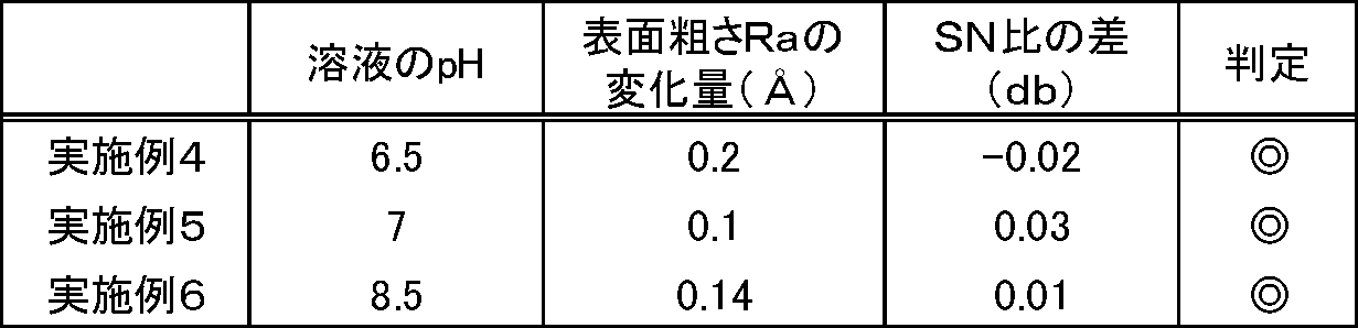


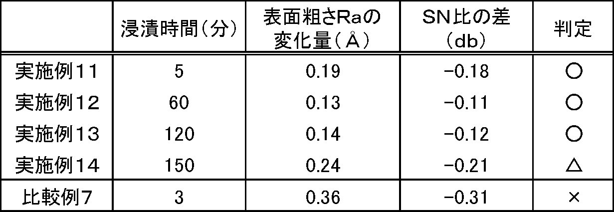

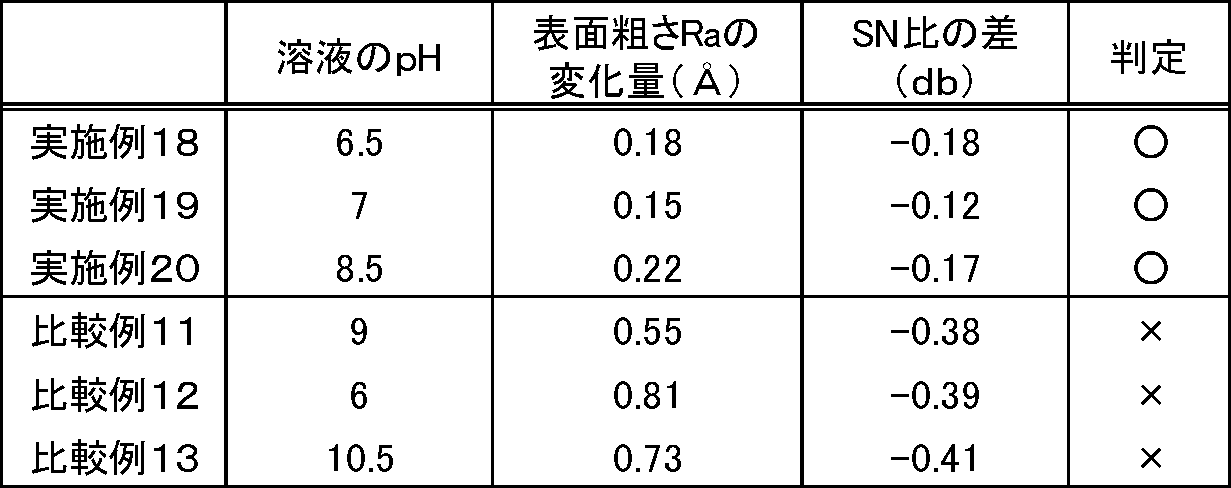

表1に示されるように、浸漬工程においてpH6.5~8.5の溶液に浸漬させた実施例1~3の製造方法により作製したガラス基板は、pHがこの範囲を外れる比較例1~3の製造方法により作製したガラス基板と比べて、表面粗さRaの変化量が小さくなった。また、実施例1~3の製造方法により作製したガラス基板を用いて作製した磁気記録媒体は、SN比の差が-0.17~-0.11dbの範囲であり、良好であった。
表2に示されるように、浸漬工程において分散剤を含む溶液を用いた実施例1~3の製造方法により作製したガラス基板は、分散剤を含まない溶液を用いた比較例4~6の製造方法により作製したガラス基板と比べて、欠陥数は同程度であったが、凝集したコロイダルシリカの数が少なく、良好であった。中でも、溶液のpHを7.0~8.0とした実施例2(pH7.0)の製造方法により作製したガラス基板は、凝集したコロイダルシリカの数が少なく、特に良好であった。
表3に示されるように、第一の予備浸漬工程をさらに含む実施例4~6の製造方法により作製したガラス基板は、第一の予備浸漬工程を含まない実施例1~3の製造方法により作製したガラス基板(表1参照)と比べて、同一pHの溶液に浸漬させた際の表面粗さRaの変化量がさらに小さくなった。また、実施例4~6の製造方法により作製したガラス基板を用いて作製した磁気記録媒体は、実施例1~3の製造方法により作製したガラス基板を用いて作製した磁気記録媒体と比べて、SN比の差が-0.02~0.03dbであり、さらに良好であった。
表4に示されるように、第二の予備浸漬工程をさらに含む実施例7~9の製造方法により作製したガラス基板は、第二の予備浸漬工程を含まない実施例1~3の製造方法により作製したガラス基板(表1参照)と、同一pHの溶液に浸漬させた際の表面粗さRaの変化量がさらに小さくなった。また、実施例7~9の製造方法により作製したガラス基板を用いて作製した磁気記録媒体は、実施例1~3の製造方法により作製したガラス基板を用いて作製した磁気記録媒体と比べて、同一pHの溶液に浸漬させた際のSN比の差が0.01~0.04dbであり、さらに良好であった。
表5に示されるように、第一の予備浸漬工程および第二の予備浸漬工程をさらに含み、浸漬時間を30分とした実施例10の製造方法により作製したガラス基板は、第一の予備浸漬工程および第二の予備浸漬工程の少なくともいずれか一方を含んでいない実施例2、実施例5、実施例8の製造方法により作製したガラス基板(それぞれ表1、表2、表3参照)と比較して、表面粗さRaの変化量がさらに小さくなった。また、実施例10の製造方法により作製したガラス基板を用いて作製した磁気記録媒体は、実施例2、5、8の製造方法により作製したガラス基板を用いて作製した磁気記録媒体と比べて、SN比の差が0.06dbであり、さらに良好であった。
表6に示されるように、浸漬工程における溶液への浸漬時間が5分以上である実施例11~14の製造方法により作製したガラス基板は、浸漬時間が5分未満(3分)である比較例7の製造方法により作製したガラス基板と比べて、表面粗さRaの変化量が小さくなった。また、実施例11~14の製造方法により作製したガラス基板を用いて作製した磁気記録媒体は、SN比の差が-0.21~-0.11dbの範囲であり、良好であった。中でも、浸漬時間が5~120分である実施例11~13の製造方法により作製したガラス基板は、SN比の差が-0.18~-0.11dbの範囲であり、特に良好であった。
表7に示されるように、浸漬工程においてリン酸系界面活性剤を含むpH6.5~8.5の溶液に浸漬させた実施例15~17の製造方法により作製したガラス基板は、pHがこの範囲を外れる比較例8~10の製造方法により作製したガラス基板と比べて、表面粗さRaの変化量が小さくなった。また、実施例15~17の製造方法により作製したガラス基板を用いて作製した磁気記録媒体は、SN比の差が-0.19~-0.13dbの範囲であり、良好であった。
表8に示されるように、浸漬工程において非イオン界面活性剤を含むpH6.5~8.5の溶液に浸漬させた実施例18~20の製造方法により作製したガラス基板は、pHがこの範囲を外れる比較例11~13の製造方法により作製したガラス基板と比べて、表面粗さRaの変化量が小さくなった。また、実施例18~20の製造方法により作製したガラス基板を用いて作製した磁気記録媒体は、SN比の差が-0.18~-0.12dbの範囲であり、良好であった。
表9に示されるように、浸漬工程においてスルホン酸系界面活性剤を含むpH6.5~8.5の溶液に浸漬させた実施例21~23の製造方法により作製したガラス基板は、pHがこの範囲を外れる比較例14~16の製造方法により作製したガラス基板と比べて、表面粗さRaの変化量が小さくなった。また、実施例21~23の製造方法により作製したガラス基板を用いて作製した磁気記録媒体は、SN比の差が-0.17~-0.13dbの範囲であり、良好であった。
本発明は、記録密度が630Gb/平方インチ以上であるHDD用ガラス基板の製造方法等の技術分野において広く利用することができる。
Claims (7)
- コロイダルシリカを含むpH4以下の研磨液で、AFMで測定した表面粗さRa(測定範囲:1μm四方)が2.0Å以下になるまでガラス基板を研磨する精密研磨工程と、
前記精密研磨工程後のガラス基板を、高周波を用いて洗浄する超音波洗浄工程と、
前記超音波洗浄工程後のガラス基板を、分散剤を含むpH6.5~8.5の溶液に5分以上浸漬させる浸漬工程と、
前記浸漬工程後のガラス基板をスクラブ洗浄するスクラブ洗浄工程とを含む、
記録密度が630Gb/平方インチ以上であるHDD用ガラス基板の製造方法。 - 前記精密研磨工程後に、分散剤を含むpH6.5~8.5の溶液にガラス基板を5分以上浸漬させる予備浸漬工程をさらに含み、
前記予備浸漬工程後に前記超音波洗浄工程を行う、請求項1記載のHDD用ガラス基板の製造方法。 - 前記スクラブ洗浄工程後に、分散剤を含むpH6.5~8.5の溶液にガラス基板を5分以上浸漬させる予備浸漬工程をさらに含む、請求項1または2記載のHDD用ガラス基板の製造方法。
- 前記溶液のpHが7~8.5であり、
前記分散剤は、ポリビニルアルコール、変性ポリビニルアルコール、ポリビニルピロリドン、(メタ)アクリル酸(共)重合体、ポリ(メタ)アクリルアミド(共)重合体、エチレングリコール、リン酸系界面活性剤、スルホン酸系界面活性剤、カルボン酸系界面活性剤および非イオン界面活性剤からなる群から選択される1または複数の化合物を含む、請求項1~3のいずれか1項に記載のHDD用ガラス基板の製造方法。 - 前記浸漬工程において、溶液のpHが6.5を下回る場合、調整剤を添加することによりpHを6.5~8.5に調整する、請求項1~4のいずれか1項に記載のHDD用ガラス基板の製造方法。
- 前記浸漬工程における溶液のpHが7.0~8.0である、請求項1~5のいずれか1項に記載のHDD用ガラス基板の製造方法。
- 前記浸漬工程において、溶液への浸漬時間が120分以下である、請求項1~6のいずれか1項に記載のHDD用ガラス基板の製造方法。
Priority Applications (2)
| Application Number | Priority Date | Filing Date | Title |
|---|---|---|---|
| JP2014554122A JP6088545B2 (ja) | 2012-12-27 | 2013-12-17 | Hdd用ガラス基板の製造方法、情報記録媒体の製造方法、及びhdd用ガラス基板 |
| CN201380060277.7A CN104798132B (zh) | 2012-12-27 | 2013-12-17 | Hdd用玻璃基板及其制造方法以及信息记录介质的制造方法 |
Applications Claiming Priority (2)
| Application Number | Priority Date | Filing Date | Title |
|---|---|---|---|
| JP2012284555 | 2012-12-27 | ||
| JP2012-284555 | 2012-12-27 |
Publications (1)
| Publication Number | Publication Date |
|---|---|
| WO2014103246A1 true WO2014103246A1 (ja) | 2014-07-03 |
Family
ID=51020367
Family Applications (1)
| Application Number | Title | Priority Date | Filing Date |
|---|---|---|---|
| PCT/JP2013/007420 Ceased WO2014103246A1 (ja) | 2012-12-27 | 2013-12-17 | Hdd用ガラス基板の製造方法 |
Country Status (3)
| Country | Link |
|---|---|
| JP (1) | JP6088545B2 (ja) |
| CN (1) | CN104798132B (ja) |
| WO (1) | WO2014103246A1 (ja) |
Citations (6)
| Publication number | Priority date | Publication date | Assignee | Title |
|---|---|---|---|---|
| JP2001206737A (ja) * | 1999-11-18 | 2001-07-31 | Nippon Sheet Glass Co Ltd | ガラス基板及びその洗浄方法 |
| JP2003266283A (ja) * | 2002-03-15 | 2003-09-24 | Nippon Sheet Glass Co Ltd | 情報記録媒体用ガラス基板の製造方法 |
| JP2006351081A (ja) * | 2005-06-14 | 2006-12-28 | Fuji Electric Holdings Co Ltd | 磁気ディスク基板の研磨方法 |
| JP2011018398A (ja) * | 2009-07-09 | 2011-01-27 | Asahi Glass Co Ltd | 情報記録媒体用ガラス基板及びその製造方法、磁気記録媒体 |
| JP2011060416A (ja) * | 2006-07-03 | 2011-03-24 | Konica Minolta Opto Inc | 情報記録媒体用ガラス基板の製造方法 |
| WO2012093516A1 (ja) * | 2011-01-07 | 2012-07-12 | 旭硝子株式会社 | 情報記録媒体用ガラス基板、その製造方法および磁気記録媒体 |
-
2013
- 2013-12-17 WO PCT/JP2013/007420 patent/WO2014103246A1/ja not_active Ceased
- 2013-12-17 CN CN201380060277.7A patent/CN104798132B/zh active Active
- 2013-12-17 JP JP2014554122A patent/JP6088545B2/ja active Active
Patent Citations (6)
| Publication number | Priority date | Publication date | Assignee | Title |
|---|---|---|---|---|
| JP2001206737A (ja) * | 1999-11-18 | 2001-07-31 | Nippon Sheet Glass Co Ltd | ガラス基板及びその洗浄方法 |
| JP2003266283A (ja) * | 2002-03-15 | 2003-09-24 | Nippon Sheet Glass Co Ltd | 情報記録媒体用ガラス基板の製造方法 |
| JP2006351081A (ja) * | 2005-06-14 | 2006-12-28 | Fuji Electric Holdings Co Ltd | 磁気ディスク基板の研磨方法 |
| JP2011060416A (ja) * | 2006-07-03 | 2011-03-24 | Konica Minolta Opto Inc | 情報記録媒体用ガラス基板の製造方法 |
| JP2011018398A (ja) * | 2009-07-09 | 2011-01-27 | Asahi Glass Co Ltd | 情報記録媒体用ガラス基板及びその製造方法、磁気記録媒体 |
| WO2012093516A1 (ja) * | 2011-01-07 | 2012-07-12 | 旭硝子株式会社 | 情報記録媒体用ガラス基板、その製造方法および磁気記録媒体 |
Also Published As
| Publication number | Publication date |
|---|---|
| CN104798132A (zh) | 2015-07-22 |
| JPWO2014103246A1 (ja) | 2017-01-12 |
| CN104798132B (zh) | 2019-05-10 |
| JP6088545B2 (ja) | 2017-03-01 |
Similar Documents
| Publication | Publication Date | Title |
|---|---|---|
| JP5386036B2 (ja) | 磁気ディスク用ガラス基板の製造方法 | |
| JP3512702B2 (ja) | 情報記録媒体用ガラス基板の製造方法、及び情報記録媒体の製造方法 | |
| JP5037975B2 (ja) | 磁気ディスク用ガラス基板の製造方法及び磁気ディスクの製造方法 | |
| JP5635078B2 (ja) | 磁気ディスク用ガラス基板の製造方法 | |
| JP2011060416A (ja) | 情報記録媒体用ガラス基板の製造方法 | |
| JP2014188668A (ja) | ガラス基板の製造方法 | |
| JP5636508B2 (ja) | ガラス基板、該ガラス基板を用いた情報記録媒体および当該ガラス基板の製造方法 | |
| JP6088545B2 (ja) | Hdd用ガラス基板の製造方法、情報記録媒体の製造方法、及びhdd用ガラス基板 | |
| JP6081580B2 (ja) | 磁気ディスク用ガラス基板の製造方法及び磁気ディスクの製造方法 | |
| JP5778165B2 (ja) | 情報記録媒体用ガラス基板の製造方法および情報記録媒体の製造方法 | |
| JP6034580B2 (ja) | Hdd用ガラス基板の製造方法 | |
| JP5859757B2 (ja) | Hdd用ガラス基板の製造方法 | |
| JP2014191851A (ja) | 情報記録媒体用ガラス基板の製造方法 | |
| JP5897959B2 (ja) | 情報記録媒体用ガラス基板の製造方法 | |
| JP6131124B2 (ja) | 情報記録媒体用ガラス基板および情報記録媒体 | |
| JP6298408B2 (ja) | 磁気ディスク用ガラス基板の製造方法及び磁気ディスクの製造方法 | |
| JP5886108B2 (ja) | 情報記録媒体用ガラス基板の製造方法 | |
| JP6034636B2 (ja) | 磁気記録媒体用基板の製造方法 | |
| WO2013099082A1 (ja) | Hdd用ガラス基板の製造方法 | |
| JP2014175023A (ja) | 磁気記録媒体用ガラス基板の製造方法 | |
| JP5722618B2 (ja) | 磁気情報記録媒体用ガラス基板の製造方法 | |
| JP6196976B2 (ja) | 情報記録媒体用ガラス基板の製造方法、情報記録媒体の製造方法、および、情報記録媒体用ガラス基板 | |
| CN103946920B (zh) | Hdd用玻璃基板的制造方法、hdd用玻璃基板以及hdd用磁记录介质 | |
| JP5360331B2 (ja) | Hdd用ガラス基板の製造方法 | |
| JP2013016216A (ja) | Hdd用ガラス基板の製造方法、hdd用ガラス基板、及びhdd用磁気記録媒体 |
Legal Events
| Date | Code | Title | Description |
|---|---|---|---|
| 121 | Ep: the epo has been informed by wipo that ep was designated in this application |
Ref document number: 13867665 Country of ref document: EP Kind code of ref document: A1 |
|
| ENP | Entry into the national phase |
Ref document number: 2014554122 Country of ref document: JP Kind code of ref document: A |
|
| NENP | Non-entry into the national phase |
Ref country code: DE |
|
| 122 | Ep: pct application non-entry in european phase |
Ref document number: 13867665 Country of ref document: EP Kind code of ref document: A1 |