WO2014103095A1 - Pince - Google Patents
Pince Download PDFInfo
- Publication number
- WO2014103095A1 WO2014103095A1 PCT/JP2013/004527 JP2013004527W WO2014103095A1 WO 2014103095 A1 WO2014103095 A1 WO 2014103095A1 JP 2013004527 W JP2013004527 W JP 2013004527W WO 2014103095 A1 WO2014103095 A1 WO 2014103095A1
- Authority
- WO
- WIPO (PCT)
- Prior art keywords
- forceps
- portions
- bent
- pair
- clamping
- Prior art date
Links
Images

Classifications
-
- A—HUMAN NECESSITIES
- A61—MEDICAL OR VETERINARY SCIENCE; HYGIENE
- A61B—DIAGNOSIS; SURGERY; IDENTIFICATION
- A61B17/00—Surgical instruments, devices or methods, e.g. tourniquets
- A61B17/28—Surgical forceps
- A61B17/2804—Surgical forceps with two or more pivotal connections
-
- A—HUMAN NECESSITIES
- A61—MEDICAL OR VETERINARY SCIENCE; HYGIENE
- A61B—DIAGNOSIS; SURGERY; IDENTIFICATION
- A61B17/00—Surgical instruments, devices or methods, e.g. tourniquets
- A61B2017/00681—Aspects not otherwise provided for
- A61B2017/00738—Aspects not otherwise provided for part of the tool being offset with respect to a main axis, e.g. for better view for the surgeon
Definitions
- the present invention relates to a forceps, and more particularly, to a forceps used for treating a living tissue during a surgical operation.
- Patent Document 1 describes “a scissor structure that is received in an endoscopic operation in an abdominal cavity or a chest cavity or in an intercostal operation. Eliminates the critical limitations of surgical instruments, provides convenience and safety that is the same as that for surgical operation under direct vision in laparotomy and thoracotomy, and also provides the economics of reducing the burden on patients and medical administration
- object (paragraph number 0004 of Patent Document 1),“ •• when the tip portion is closed, the handle portions intersect each other between the fulcrum and the grip portion.
- “Surgery instrument to perform” (Claim 1 of Patent Document 1).
- Patent Document 2 discloses a forceps that accurately clamps hemorrhoids in a narrow anal canal and suppresses bleeding at the time of suturing. "Surgical forceps characterized by being gently curved" (Claim 1 of Patent Document 2).
- the forceps used in the surgical operation have been developed with various shapes depending on the use situation and the like.
- the burden on the patient and the medical staff is reduced, and convenience and safety are reduced. Further development of the provided forceps is desired.
- a blood vessel running through the body from an incised hole is clamped with forceps to stop bleeding, the forceps tend to stand up from the body surface. It tends to tilt toward the outside, and an extra force is easily applied to the blood vessel. Since a blood vessel is a delicate tissue, if an excessive force is applied, the living tissue is damaged, and the endothelial tissue is easily damaged or a thrombus is easily generated without being cut or destroyed.
- the present invention has been made to solve such a problem, and provides a forceps that does not interfere with surgical operation in a surgical field in surgery, has excellent operability, and does not easily damage a biological tissue such as a blood vessel. For the purpose.
- a pair of forceps members has a clamping part on one side, an operation part on the other side, and a motion transmission part between the clamping part and the operation part, and the motion transmission according to opening and closing of the operation part.
- a forceps that opens and closes the clamping part via a part,
- Each of the operation part and the clamping part has at least one bent part,
- the movement transmitting unit is a forceps that forms a lever mechanism that transmits an opening / closing movement of the operation unit as an opening / closing movement of the clamping unit.
- An angle ⁇ 1 formed by the first plane including the pair of operation units and the second plane including the pair of motion transmission units is 105 to 135 °
- the clamping portion is the forceps according to (1) or (2), which includes two bent portions, (4)
- the bending angle of the second bending portion adjacent to the motion transmitting portion in the clamping portion and the bending angle of the third bending portion adjacent to the second bending portion in the clamping portion are 105 to 135 °, respectively.
- the length of the operation part is 40 to 80 mm
- the length from the tip of the clamping part to the third bent part is 1 to 5 mm
- the length from the third bent part to the second bent part is 0
- the operation portion since the operation portion has at least one bent portion, the portion of the conventional forceps that is standing from the body surface when sandwiching a biological tissue such as a blood vessel in the body is Since they are arranged along the front surface, no excessive force is applied to the living tissue such as blood vessels, so that it is difficult to damage the living tissue, and the forceps do not interfere with the surgical operation in the operative field.
- the said clamping part since the said clamping part has at least 1 bending part, biological tissues, such as a blood vessel, can be clamped in the posture where the clamping part inserted in the body is not unreasonable, and it is hard to damage a biological tissue.
- the movement transmitting unit forms a lever mechanism that transmits the opening / closing movement of the operation unit as the opening / closing movement of the clamping unit, the shape of the movement transmitting unit hardly changes during the opening / closing movement.
- the holding part can be opened and closed in a state where the pair of motion transmission parts are hardly separated from each other, the operability when holding a biological tissue such as a blood vessel in a limited space at the incision site is excellent.
- FIG. 1 is a schematic explanatory view of a forceps showing one embodiment of a forceps according to the present invention.
- FIG. 1A is a schematic top view of a forceps showing an embodiment of the forceps according to the present invention
- FIG. 1B is a schematic side view of the forceps showing an embodiment of the forceps according to the present invention.
- FIG. FIG. 2 is a main part schematic diagram showing the motion transmission part in an enlarged manner.
- FIG. 2 (a) is an enlarged schematic view of the main part of the motion transmitting part when the clamping part is closed
- FIG. 2 (b) shows the motion when the clamping part is open. It is a principal part schematic diagram which expands and shows a transmission part.
- FIG. 1A is a schematic top view of a forceps showing an embodiment of the forceps according to the present invention
- FIG. 1B is a schematic side view of the forceps showing an embodiment of the forceps according to the present invention.
- FIG. 3 is a schematic explanatory view of a forceps showing another embodiment of the forceps according to the present invention.
- FIG. 3A is a schematic top view of a forceps showing an embodiment of the forceps according to the present invention
- FIG. 3B is a schematic side view of the forceps showing an embodiment of the forceps according to the present invention.
- FIG. 1 is a schematic explanatory view of a forceps showing one embodiment of a forceps according to the present invention.
- FIG. 1A is a schematic top view of a forceps showing an embodiment of the forceps according to the present invention
- FIG. 1B is a schematic side view of the forceps showing an embodiment of the forceps according to the present invention.
- the forceps 1 of this embodiment includes a pair of forceps members 2 having one holding portion 3a, 3b, the other operation portion 4a, 4b, and the holding portion 3a, 3b and the operation portion 4a. 4b, movement transmitting portions 5a and 5b are respectively provided, and the holding portions 3a and 3b are opened and closed via the movement transmitting portions 5a and 5b according to the opening and closing of the operation portions 4a and 4b.
- the forceps member 2 can be formed of a material generally used as a material for medical forceps, for example, titanium, a titanium alloy such as Ti6Al4, stainless steel, or the like.
- the operation units 4a and 4b are portions that are opened and closed by a medical worker and open and close the pair of operation units 4a and 4b.
- the operation parts 4a and 4b are ring-shaped ring parts 6a and 6b for inserting fingers, handle parts 7a and 7b extending from the ring parts 6a and 6b, and ring parts 6a and 6b of the handle parts 7a and 7b.
- And ratchet portions 8a and 8b provided on opposite sides of the pair of handle portions 7a and 7b at the end portions on the side.
- the length of the operation parts 4a and 4b is preferably 40 to 80 mm, for example, 60 mm, from the viewpoint of the use part of the forceps and the operability.
- the handle portions 7a and 7b have first bent portions A that are bent to the opposite side to the side where the fingers are inserted in the ring portions 6a and 6b.
- the bending angle at the first bent portion A is from the end of the pair of operation portions 4a and 4b to the first bent portion A when the pair of operation portions 4a and 4b are viewed from the side.
- plane a first plane including a central axis, a pair of motion transmitting portion 5a, a plane including the central axis of 5b as a second plane can be represented by the angle theta 1 between the first and second planes, ⁇ 1 is 120 °.
- the angle ⁇ 1 formed in the forceps 1 of this embodiment is 120 °.
- the ring parts 6a and 6b are placed on the body surface.
- the angle may be any angle as long as it is disposed along the line, and ⁇ 1 is preferably 105 ° to 135 °, and more preferably 115 ° to 125 °.
- the forceps may stand up from the body surface.
- the operation portions 4a and 4b, particularly the ring portion 6a. , 6b is arranged along the body surface, so that excessive force is not applied to the living tissue such as blood vessels, so that it is difficult to damage the living tissue, and the forceps do not interfere with the surgical operation in the operative field.
- one of the handle portions 7a, 7b is integrally formed with one of the motion transmitting portions 5a when the pair of operation portions 4a, 4b are viewed from above. It extends in a straight line.
- the other handle portion 7b is connected to the other motion transmission portion 5b as a separate body and connected at a predetermined angle. Accordingly, the one handle 7a and the other handle 7b are the ends on the side of the motion transmitting portions 5a and 5b so that one handle 7a, the other handle 7b, and the ratchet 8a, 8b form a triangle. It intersects at a predetermined angle at the part.
- the length of the handle portions 7a and 7b is not particularly limited, but is 20 to 60 mm, for example, in consideration of the use site and operability of the forceps.
- the cross-sectional shape of the handle portions 7a and 7b is, for example, a square with R added to the corner, and the dimension is 1.5 to 2.5 mm ⁇ 1 to 2 mm, for example 2.0 mm ⁇ 1.5 mm. It should be noted that all the corners of the outer surface of the forceps 1 are preferably marked with R so as not to damage the living tissue.
- the ratchet portions 8a and 8b are formed so that the opening angles of the holding portions 3a and 3b can be positioned so that the holding portions 3a and 3b do not open and close after holding an object to be held such as a blood vessel.
- the ratchet portions 8a and 8b extend from one operation portion 4a and 4b toward the other operation portion 4b and 4a.
- the pair of ratchet portions 8a and 8b are closed, the pair of ratchet portions 8a and 8b.
- the closed state of the pair of operation parts 4a and 4b does not mean a state in which the pair of operation parts 4a and 4b, particularly the pair of handle parts 7a and 7b are in contact with each other in parallel, but a pair of operations.
- the parts 4a and 4b intersect at a predetermined angle, and even if a force is applied in the direction in which the pair of operation parts 4a and 4b approach each other, the angle does not decrease any more.
- 2 to 10 ridges and valleys are formed on the surface where the pair of ratchet portions 8a and 8b are opposed to each other.
- the ridge formed on one ratchet portion 8a and 8b and the other ratchet portion 8b are formed.
- the clamping portions 3a and 3b can be fixed in an open state at a specific angle depending on the size of the sandwiched object. Yes.
- the operator When releasing this fixed state, the operator inserts a finger into the ring portions 6a and 6b and applies a force of a predetermined level or more in a direction to separate the pair of operation portions 4a and 4b, so that the ratchet portion 8a, By disengaging one peak and the other valley in 8b.
- the movement transmitting parts 5a and 5b form a double lever mechanism that transmits the opening and closing movements of the operation parts 4a and 4b as the opening and closing movements of the clamping parts 3a and 3b. Since the motion transmission units 5a and 5b form a lever mechanism, the shape of the motion transmission units 5a and 5b hardly changes during opening and closing movements. In other words, the pair of motion transmission units 5a and 5b are almost identical to each other.
- the clamping portions 3a and 3b can be opened and closed without being separated. In order to reduce the burden on the patient, the length of the incision site is usually kept to a minimum.
- the conventional forceps that is the same mechanism as the scissors, that is, a forceps member is overlapped with a hinge as a pivot, and is opened and closed.
- the pair of forceps members are opened and closed in a fan shape around the hinge, so that a space corresponding to the opening and closing width is required.
- the handle extending from the hinge to the rear end side becomes longer, so the opening / closing width is increased accordingly, to other forceps and incision sites. The operability is likely to deteriorate due to contact with the surface.
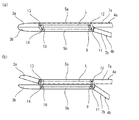
- FIG. 2 is an enlarged schematic view of the main part showing the motion transmission part
- FIG. 2 (a) shows the motion transmission part when the clamping part is closed
- FIG. 2 (b) shows the clamping.
- the movement transmission part when a part is an open state is shown.
- one motion transmitting portion 5b and the other motion transmitting portion 5a are composed of the first link 9 at the tip of one operating portion 4b and the other clamping portion 3a.
- the second link 10 at the proximal end is connected via four pins from the first pin 11 to the fourth pin 14.
- the first link 11 and the second link 12 act as a lever
- one motion transmission portion 5b acts as a fixed link to form a double lever mechanism.
- the first pin 11, the second pin 12, the third pin 13, the fourth pin 14, and Virtual lines L connecting the first pins 11 in the order of the first pins 11 form a parallelogram.
- the imaginary line L has a shape approximating a rectangle, and between the pair of motion transmitting portions 5a and 5b. Is slightly separated by, for example, 0.1 to 0.5 mm.
- the outer shapes of the motion transmitting units 5a and 5b are hardly changed by opening and closing the clamping units 3a and 3b.
- the cross-sectional shape and thickness of the motion transmitting portions 5a and 5b can be a shape and thickness approximate to the handle portions 7a and 7b, and the length is 15 to from the viewpoint of the use site of the forceps and the operability. It is preferably 50 mm, for example 25 mm.
- One motion transmission portion 5b is linearly connected to one clamping portion 5b and acts as a fixed link.
- the movement transmitting portion 5b and the first link 9 at the end of the one operation portion 4b are connected via the first pin 11, and the one operation portion 4b rotates around the first pin 11.
- the end of the first link 9 opposite to the first pin 11 is connected to the other motion transmission portion 5a via the second pin 12, and the other motion transmission is performed according to the rotation of one operation portion 4b.
- the part 5a responds.
- the other motion transmitting portion 5a is integrally connected to the other operation portion 4a in a straight line, and is connected to the second link 10 at the proximal end of the other holding portion 3a via a third pin 13.
- An end portion of the second link 10 opposite to the third pin 13 is connected to one motion transmission portion 5 b via a fourth pin 14.
- the other motion transmission unit 5a connected to the first link 9 via the second pin 12 responds with the rotation of the one operation unit 4b
- the second link 10 responds with this response,
- the other clamping part 3a rotates around the fourth pin 14.
- the first link 9 is provided at a predetermined angle with respect to the handle portion 7b
- the second link 10 is provided at a predetermined angle with respect to the holding portion 3a.
- the first link 9 and the second link 10 are slightly longer than the total length of the motion transmitting portions 5a and 5b. Therefore, when the clamping portions 3a and 3b are closed, the pair of motion transmission portions 5a and 5b are in contact with each other, and the first link 9 and the second link 10 are orthogonal to the longitudinal direction of the motion transmission portions 5a and 5b.
- the first link 9 and the second link 10 are formed so as not to protrude from the width direction of the motion transmitting units 5a and 5b. Further, as shown in FIG.
- the first link 9 and the second link 10 are arranged in a direction substantially orthogonal to the motion transmitting portions 5a and 5b.
- the first link 9 and the second link 10 are formed so as not to protrude from the width direction of the motion transmitting portions 5a and 5b, and the motion transmitting portions 5a and 5b are slightly separated from each other.
- the clamping parts 3a and 3b clamp biological tissues such as blood vessels in a living body, sutures, instruments, and the like.
- the sandwiching portions 3a and 3b open and close when the opening / closing motions of the operation portions 4a and 4b are transmitted through the motion transmitting portions 5a and 5b.
- the rotational movement of one operation part 4b is transmitted as the rotational movement of the other clamping part 3a by both lever mechanisms, and the clamping parts 3a and 3b are opened and closed.
- the sandwiching portions 3a and 3b are adjacent to the motion transmitting portions 5a and 5b, adjacent to the second bent portion B bent to the opposite side of the first bent portion A, and adjacent to the second bent portion B. And a third bent portion C bent in the same direction as the bent portion B.
- the bending angle at the second bending portion B is such that when the forceps 1 is viewed from the side, the plane including the central axis of the pair of motion transmitting portions 5a and 5b is the second plane and the pair of sandwiched portions.
- ⁇ 2 is 120 °.
- the angle ⁇ 2 formed in the forceps 1 of this embodiment is 120 °, but it may be any angle as long as the object to be clamped in the body can be clamped in a reasonable posture, and ⁇ 2 is 105 ° to 135 °. It is preferred that the angle is 115 ° to 125 °.
- the bending angle at the third bent portion C is such that when the forceps 1 is viewed from the side, a plane including the central axis between the third bent portion C and the tip of the pair of sandwiching portions 3a and 3b is defined as a fourth plane. It can be represented by an angle ⁇ 3 formed by the third plane and the fourth plane, and ⁇ 3 is 120 °.
- the angle ⁇ 3 formed by the forceps 1 of this embodiment may be any angle that allows the object to be clamped in the body to be held in a comfortable posture, and ⁇ 3 is preferably 105 ° to 135 °, and 115 It is particularly preferred that the angle is from ° to 125 °.
- the clamping portions 3a and 3b of the forceps 1 are bent at an angle within the above range, a living tissue such as a blood vessel in a living body can be held in a comfortable posture, so that the living tissue such as a blood vessel cannot be forced. It is difficult to damage the living tissue.
- the first bent portion A, the second bent portion B, and the third bent portion C described above are all bent at an appropriate bending radius.
- the length of the sandwiching portions 3a and 3b is not particularly limited.
- the length from the tip of the sandwiching portions 3a and 3b to the third bent portion C is 1 to 5 mm, for example 3 mm.
- the length to the second bent portion B is 0 to 20 mm, particularly 1 to 10 mm, for example 10 mm, and the length from the second bent portion B to the end connected to the motion transmitting portions 5a and 5b is 1 to 1 mm. 10 mm, for example 5 mm.
- the outer peripheral surfaces of the sandwiching portions 3a and 3b have an appropriate roundness so as not to damage the living tissue.
- the thickness of the sandwiching portions 3a, 3b is, for example, thinner than the handle portions 7a, 7b, and is formed so as to become gradually thinner toward the tip.
- the cross section in the vicinity of the center in the longitudinal direction of the sandwiching portions 3a, 3b is 0.8 to 1.8 ⁇ 0.5 to 1.5 mm, for example 1.3 mm ⁇ 1.0 mm.
- the opposing surfaces that the pair of sandwiching portions 3a and 3b face may be flat surfaces, and when the sandwiched object is sandwiched, the sandwiched object can be reliably secured with an appropriate frictional force without damaging the sandwiched object.
- interposed may be formed.
- the movement transmitting portion 5a responds, and with this response, the second link 10 rotates around the fourth pin so as to approach the direction perpendicular to the longitudinal direction of the motion transmitting portions 5a and 5b.
- the other holding portion 3a integrally connected to the two links 10 rotates around the fourth pin 14 in a direction away from the one holding portion 3b.
- a clamping object such as a blood vessel is arranged between the pair of clamping parts 3a and 3b. Since the clamping portions 3a and 3b have the second bent portion B and the third bent portion C, for example, even if the blood vessel is disposed in a place where it is difficult to hold in the living body, an excessive force is exerted on the blood vessel and its surrounding tissue. A blood vessel can be disposed between the pair of sandwiching portions 3a and 3b so as not to apply.
- the one operation unit 4b rotates around the first pin 11 in a direction to approach the other operation unit 4a.
- the other motion transmission unit 5a connected to the first link 9 via the second pin 12 responds, and the second link 10 responds according to this response.
- the other clamping part 3a rotates around the fourth pin 14 in a direction approaching the one clamping part 3b.
- the operation parts 4a and 4b do not stand from the body surface from 5a and 5b, and the ring parts 6a and 6b in the operation parts 4a and 4b are arranged along the body surface. Therefore, the forceps 1 do not come into contact with the operator's hand in the subsequent surgical operation and do not get in the way.
- the posture of the ring portions 6a and 6b is not greatly changed, for example, the tilts according to gravity, so that it is impossible for the sandwiched object and the surrounding tissue. It is difficult to damage the living tissue.
- the pair of movement transmitting parts 5a and 5b are slightly separated from each other, and the outer shape thereof hardly changes. Therefore, even when the forceps 1 is inserted into a small incision site and used, it is difficult to contact the forceps or the like previously arranged, and the operability is excellent.
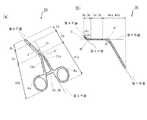
- FIG. 3 is a schematic explanatory view of a forceps showing another embodiment of the forceps according to the present invention.
- FIG. 3A is a schematic top view of a forceps showing an embodiment of the forceps according to the present invention
- FIG. 3B is a schematic side view of the forceps showing an embodiment of the forceps according to the present invention.
- the forceps 20 of the embodiment shown in FIG. 3 is the same as the forceps 1 shown in FIG. 1 except that the bending direction of the first bent portion A ′ in the operation portions 41a and 41b is different from that of the forceps 1 shown in FIG. 3, members having the same shape as the members shown in FIG. 1 are denoted by the same reference numerals as those shown in FIG.
- the handle portions 71a and 71b of the forceps 20 of this embodiment have a first bent of the forceps 1 shown in FIG. 1 (b) when the pair of operation portions 41a and 41b are viewed from the side.
- the first bent portion A ′ is bent similarly to the portion A. Therefore, the angle theta 1 between the first and second planes is 120 °, are bent to the opposite side to the side of inserting the finger in the ring portion at the same angle as the forceps 1 shown in FIG.
- the handle portions 71a and 71b of the forceps 20 of this embodiment are bent toward the one ring portion 6b when the pair of operation portions 41a and 41b are viewed from above. 1 is different from the handle portions 7a and 7b in the forceps 1 shown in FIG.
- a plane that is orthogonal to the first plane and that includes the central axis of the handle 71a on which the operating portion 41a and the motion transmitting portion 5a are integrally connected is a fifth plane, orthogonal to the first plane, and the plane in which the operation unit 41a and the motion transmitting portion 5a includes a center axis of the motion transmitting portion 5a of those who are connected together as a sixth plane, when the angle between the fifth plane and a sixth plane and theta 4 , the angle theta 4 is 20 °.
- the handle portions 71a and 71b are bent toward the one ring portion 6b, but may be bent toward the other ring portion 6a.
- the formed angle ⁇ 4 may be in the range of ⁇ 20 ° to 0 ° or 0 ° to 20 ° (when the forceps 20 is viewed from the upper surface, the first bent portion A ′ is the center, and the fifth plane is (Anti-clockwise angle as the axis is positive.) If the handle portions 71a and 71b are bent at an angle in the above range so as to bend toward the one ring portion 6a or 6b, the object to be clamped by the forceps 20 is shifted laterally from the incision site. Even when it is in a position where it is difficult to hold, it can be held without applying excessive force to the living tissue.
- the second bent portion B and the third bent portion C in the holding portions 3a and 3b of the forceps 1 are both bent on the side opposite to the first bent portion A, but are provided on the holding portions 3a and 3b.
- the direction in which the bent portion is bent is not particularly limited, and may be bent in any direction of 360 ° as viewed from the axial direction of the motion transmitting portions 5a and 5b, and is bent in the same direction as the first bent portion A.
- the forceps 1 may be bent so as to be bent toward one of the ring portions 6a or 6b when viewed from above.
- the number of the bent portions in the sandwiching portions 3a and 3b is not limited to two, and it is sufficient that at least one bent portion is provided.
- the operation parts 4a and 4b of the forceps 1 have the first bent part A bent to the side opposite to the finger insertion side in the ring parts 6a and 6b, but the number of the bent parts is not particularly limited. You may have two or more bending parts.
- the forceps 1 that is operated by inserting an operator's finger into the ring portions 6a and 6b of the operation portions 4a and 4b has been described.
- the forceps according to the present invention are attached to the distal end of the arm of the medical robot. It can also be used as a manipulator to be attached.
- the forceps of the present invention are used to treat living tissue in a surgical operation, for example, to clamp a blood vessel to stop hemostasis, to clamp a suture thread, a belt, or the like used to stop a blood vessel. used.
- the forceps according to the present invention hardly changes the outer shape of the motion transmitting unit when clamping the object to be clamped, and the operation unit and the clamping unit are appropriately bent. It is difficult to hurt, and does not interfere with the operation of the surgical operation and is excellent in operability. Therefore, the forceps according to the present invention is suitably used for, for example, a thrombectomy operation such as a carotid artery, which has a small incision area and performs a surgical operation in a limited space.
Abstract
L'invention concerne une pince qui ne gêne pas les gestes du chirurgien pendant une intervention, qui est extrêmement maniable, et qui ne risque pas de léser du tissu vivant, par exemple des vaisseaux sanguins. La pince selon l'invention comprend une section de préhension située sur l'un des éléments de la pince, et une section d'intervention située sur l'autre élément, et une section de transmission du mouvement qui est située entre la section de préhension et la section d'intervention. La section de préhension s'ouvre et se ferme en fonction de l'ouverture et de la fermeture de la section d'intervention par l'intermédiaire de la section de transmission du mouvement. La pince est caractérisée en ce que la section d'intervention et la section de préhension comprennent l'une et l'autre au moins une section incurvée, et en ce que la section de transmission du mouvement comprend un mécanisme de levier double qui transmet le mouvement d'ouverture et de fermeture de la section d'intervention en tant que mouvement d'ouverture et de fermeture de la section de préhension.
Priority Applications (1)
| Application Number | Priority Date | Filing Date | Title |
|---|---|---|---|
| JP2014554065A JPWO2014103095A1 (ja) | 2012-12-27 | 2013-07-25 | 鉗子 |
Applications Claiming Priority (2)
| Application Number | Priority Date | Filing Date | Title |
|---|---|---|---|
| JP2012-284292 | 2012-12-27 | ||
| JP2012284292 | 2012-12-27 |
Publications (1)
| Publication Number | Publication Date |
|---|---|
| WO2014103095A1 true WO2014103095A1 (fr) | 2014-07-03 |
Family
ID=51020238
Family Applications (1)
| Application Number | Title | Priority Date | Filing Date |
|---|---|---|---|
| PCT/JP2013/004527 WO2014103095A1 (fr) | 2012-12-27 | 2013-07-25 | Pince |
Country Status (2)
| Country | Link |
|---|---|
| JP (1) | JPWO2014103095A1 (fr) |
| WO (1) | WO2014103095A1 (fr) |
Cited By (4)
| Publication number | Priority date | Publication date | Assignee | Title |
|---|---|---|---|---|
| CN103536340A (zh) * | 2013-10-29 | 2014-01-29 | 乔彬 | 一种用于心外科微创手术的腔静脉分离钳 |
| CN104323862A (zh) * | 2014-11-24 | 2015-02-04 | 江苏芸迪医疗科技发展有限公司 | 单孔双关节医疗器械 |
| CN108403186A (zh) * | 2018-03-07 | 2018-08-17 | 上手金钟手术器械江苏有限公司 | 一种医用弯杆钳 |
| CN112203591A (zh) * | 2018-10-26 | 2021-01-08 | 怡忠生命科学有限公司 | 血管打孔器 |
Citations (5)
| Publication number | Priority date | Publication date | Assignee | Title |
|---|---|---|---|---|
| JPS59114108U (ja) * | 1983-01-21 | 1984-08-01 | 国崎 拓 | 結「さつ」用鉗子 |
| JPH09266911A (ja) * | 1996-04-01 | 1997-10-14 | Shizuka Kaseda | 鉗 子 |
| JP2001245893A (ja) * | 2000-03-03 | 2001-09-11 | Jms Co Ltd | 手術用鉗子 |
| US20070032810A1 (en) * | 2004-02-25 | 2007-02-08 | Martin Storz | Medical cutting and/or holding instrument |
| JP2008536568A (ja) * | 2005-04-13 | 2008-09-11 | シンセス・ゲゼルシヤフト・ミツト・ベシユレンクテル・ハフツング | 鉗子及びそれを用いたシステム |
Family Cites Families (2)
| Publication number | Priority date | Publication date | Assignee | Title |
|---|---|---|---|---|
| US6878110B2 (en) * | 2002-01-14 | 2005-04-12 | Seung Choul Yang | Surgical instruments and method for creating anatomic working space in minilaparotomy procedure |
| CA2543792A1 (fr) * | 2003-11-05 | 2005-07-14 | Applied Medical Resources Corporation | Lame de ciseaux a angles multiples |
-
2013
- 2013-07-25 WO PCT/JP2013/004527 patent/WO2014103095A1/fr active Application Filing
- 2013-07-25 JP JP2014554065A patent/JPWO2014103095A1/ja active Pending
Patent Citations (5)
| Publication number | Priority date | Publication date | Assignee | Title |
|---|---|---|---|---|
| JPS59114108U (ja) * | 1983-01-21 | 1984-08-01 | 国崎 拓 | 結「さつ」用鉗子 |
| JPH09266911A (ja) * | 1996-04-01 | 1997-10-14 | Shizuka Kaseda | 鉗 子 |
| JP2001245893A (ja) * | 2000-03-03 | 2001-09-11 | Jms Co Ltd | 手術用鉗子 |
| US20070032810A1 (en) * | 2004-02-25 | 2007-02-08 | Martin Storz | Medical cutting and/or holding instrument |
| JP2008536568A (ja) * | 2005-04-13 | 2008-09-11 | シンセス・ゲゼルシヤフト・ミツト・ベシユレンクテル・ハフツング | 鉗子及びそれを用いたシステム |
Cited By (7)
| Publication number | Priority date | Publication date | Assignee | Title |
|---|---|---|---|---|
| CN103536340A (zh) * | 2013-10-29 | 2014-01-29 | 乔彬 | 一种用于心外科微创手术的腔静脉分离钳 |
| CN104323862A (zh) * | 2014-11-24 | 2015-02-04 | 江苏芸迪医疗科技发展有限公司 | 单孔双关节医疗器械 |
| CN108403186A (zh) * | 2018-03-07 | 2018-08-17 | 上手金钟手术器械江苏有限公司 | 一种医用弯杆钳 |
| CN112203591A (zh) * | 2018-10-26 | 2021-01-08 | 怡忠生命科学有限公司 | 血管打孔器 |
| KR20210084342A (ko) * | 2018-10-26 | 2021-07-07 | 3알 인터내셔널 씨오 엘티디 | 혈관 펀치 |
| EP3870072A4 (fr) * | 2018-10-26 | 2022-05-18 | 3R Life Sciences Corporation | Poinçon vasculaire |
| KR102647635B1 (ko) | 2018-10-26 | 2024-03-14 | 3알 라이프 사이언스 코퍼레이션 | 혈관 펀치 |
Also Published As
| Publication number | Publication date |
|---|---|
| JPWO2014103095A1 (ja) | 2017-01-12 |
Similar Documents
| Publication | Publication Date | Title |
|---|---|---|
| EP3179952B1 (fr) | Préhension à avantage mécanique commandée par robot | |
| AU2015302216B2 (en) | Robotically controlling mechanical advantage gripping | |
| JP6791846B2 (ja) | 操縦可能器具用のトルク伝達操縦機構 | |
| EP0598607A2 (fr) | Instrument endoscopique atraumatique | |
| WO2014103095A1 (fr) | Pince | |
| EP2939618B1 (fr) | Instrument chirurgical | |
| US20220323090A1 (en) | Surgical instruments with coupling members to effect multiple pivot axes | |
| CN113679449A (zh) | 铰接超声手术仪器和系统 | |
| EP3821832A1 (fr) | Préhenseur chirurgical | |
| JP2022544973A (ja) | 嚢開創器 | |
| US20050043582A1 (en) | Surgical instrument having an increased range of motion | |
| JP2012232066A (ja) | クリップ操作用鉗子,クリップ着脱用鉗子及びクリップ並びにこれらで構成される内視鏡下外科手術器具セット | |
| US20230277192A1 (en) | Actuator handle for surgical tools | |
| JP6111320B2 (ja) | 生体内導入器具 | |
| KR20140134360A (ko) | 수술용 장치 및 이를 구비하는 수술용 로봇 | |
| JP2018000340A (ja) | 生体組織把持機構 | |
| CN216962626U (zh) | 末端执行器、手术器械及手术机器人 | |
| JP4059579B2 (ja) | 外科手術用器具 | |
| US20190223897A1 (en) | Surgical instrument including flat and curved handle surfaces | |
| JP2021122312A (ja) | 医療用器具 | |
| WO2019192067A1 (fr) | Instrument chirurgical portatif et son procédé d'utilisation | |
| JP2016137029A (ja) | 外科手術用器具 | |
| KR102202030B1 (ko) | 수술용 로봇 시스템의 조작 장치 | |
| JP6310051B1 (ja) | 医療用器具 | |
| JP2001245893A (ja) | 手術用鉗子 |
Legal Events
| Date | Code | Title | Description |
|---|---|---|---|
| 121 | Ep: the epo has been informed by wipo that ep was designated in this application |
Ref document number: 13866672 Country of ref document: EP Kind code of ref document: A1 |
|
| ENP | Entry into the national phase |
Ref document number: 2014554065 Country of ref document: JP Kind code of ref document: A |
|
| NENP | Non-entry into the national phase |
Ref country code: DE |
|
| 122 | Ep: pct application non-entry in european phase |
Ref document number: 13866672 Country of ref document: EP Kind code of ref document: A1 |