WO2014097966A1 - 光学積層体の製造方法及び光学積層体 - Google Patents
光学積層体の製造方法及び光学積層体 Download PDFInfo
- Publication number
- WO2014097966A1 WO2014097966A1 PCT/JP2013/083389 JP2013083389W WO2014097966A1 WO 2014097966 A1 WO2014097966 A1 WO 2014097966A1 JP 2013083389 W JP2013083389 W JP 2013083389W WO 2014097966 A1 WO2014097966 A1 WO 2014097966A1
- Authority
- WO
- WIPO (PCT)
- Prior art keywords
- resin film
- liquid crystal
- stretched resin
- film
- crystal compound
- Prior art date
- Legal status (The legal status is an assumption and is not a legal conclusion. Google has not performed a legal analysis and makes no representation as to the accuracy of the status listed.)
- Ceased
Links
Images

Classifications
-
- B—PERFORMING OPERATIONS; TRANSPORTING
- B29—WORKING OF PLASTICS; WORKING OF SUBSTANCES IN A PLASTIC STATE IN GENERAL
- B29D—PRODUCING PARTICULAR ARTICLES FROM PLASTICS OR FROM SUBSTANCES IN A PLASTIC STATE
- B29D11/00—Producing optical elements, e.g. lenses or prisms
- B29D11/00634—Production of filters
- B29D11/00644—Production of filters polarizing
-
- B—PERFORMING OPERATIONS; TRANSPORTING
- B29—WORKING OF PLASTICS; WORKING OF SUBSTANCES IN A PLASTIC STATE IN GENERAL
- B29D—PRODUCING PARTICULAR ARTICLES FROM PLASTICS OR FROM SUBSTANCES IN A PLASTIC STATE
- B29D11/00—Producing optical elements, e.g. lenses or prisms
- B29D11/0073—Optical laminates
-
- G—PHYSICS
- G02—OPTICS
- G02B—OPTICAL ELEMENTS, SYSTEMS OR APPARATUS
- G02B5/00—Optical elements other than lenses
- G02B5/30—Polarising elements
- G02B5/3016—Polarising elements involving passive liquid crystal elements
-
- G—PHYSICS
- G02—OPTICS
- G02F—OPTICAL DEVICES OR ARRANGEMENTS FOR THE CONTROL OF LIGHT BY MODIFICATION OF THE OPTICAL PROPERTIES OF THE MEDIA OF THE ELEMENTS INVOLVED THEREIN; NON-LINEAR OPTICS; FREQUENCY-CHANGING OF LIGHT; OPTICAL LOGIC ELEMENTS; OPTICAL ANALOGUE/DIGITAL CONVERTERS
- G02F1/00—Devices or arrangements for the control of the intensity, colour, phase, polarisation or direction of light arriving from an independent light source, e.g. switching, gating or modulating; Non-linear optics
- G02F1/01—Devices or arrangements for the control of the intensity, colour, phase, polarisation or direction of light arriving from an independent light source, e.g. switching, gating or modulating; Non-linear optics for the control of the intensity, phase, polarisation or colour
- G02F1/13—Devices or arrangements for the control of the intensity, colour, phase, polarisation or direction of light arriving from an independent light source, e.g. switching, gating or modulating; Non-linear optics for the control of the intensity, phase, polarisation or colour based on liquid crystals, e.g. single liquid crystal display cells
- G02F1/133—Constructional arrangements; Operation of liquid crystal cells; Circuit arrangements
- G02F1/1333—Constructional arrangements; Manufacturing methods
- G02F1/1335—Structural association of cells with optical devices, e.g. polarisers or reflectors
- G02F1/133528—Polarisers
-
- B—PERFORMING OPERATIONS; TRANSPORTING
- B29—WORKING OF PLASTICS; WORKING OF SUBSTANCES IN A PLASTIC STATE IN GENERAL
- B29C—SHAPING OR JOINING OF PLASTICS; SHAPING OF MATERIAL IN A PLASTIC STATE, NOT OTHERWISE PROVIDED FOR; AFTER-TREATMENT OF THE SHAPED PRODUCTS, e.g. REPAIRING
- B29C55/00—Shaping by stretching, e.g. drawing through a die; Apparatus therefor
- B29C55/02—Shaping by stretching, e.g. drawing through a die; Apparatus therefor of plates or sheets
- B29C55/04—Shaping by stretching, e.g. drawing through a die; Apparatus therefor of plates or sheets uniaxial, e.g. oblique
-
- B—PERFORMING OPERATIONS; TRANSPORTING
- B29—WORKING OF PLASTICS; WORKING OF SUBSTANCES IN A PLASTIC STATE IN GENERAL
- B29K—INDEXING SCHEME ASSOCIATED WITH SUBCLASSES B29B, B29C OR B29D, RELATING TO MOULDING MATERIALS OR TO MATERIALS FOR MOULDS, REINFORCEMENTS, FILLERS OR PREFORMED PARTS, e.g. INSERTS
- B29K2023/00—Use of polyalkenes or derivatives thereof as moulding material
- B29K2023/38—Polymers of cycloalkenes, e.g. norbornene or cyclopentene
-
- B—PERFORMING OPERATIONS; TRANSPORTING
- B29—WORKING OF PLASTICS; WORKING OF SUBSTANCES IN A PLASTIC STATE IN GENERAL
- B29K—INDEXING SCHEME ASSOCIATED WITH SUBCLASSES B29B, B29C OR B29D, RELATING TO MOULDING MATERIALS OR TO MATERIALS FOR MOULDS, REINFORCEMENTS, FILLERS OR PREFORMED PARTS, e.g. INSERTS
- B29K2105/00—Condition, form or state of moulded material or of the material to be shaped
- B29K2105/0079—Liquid crystals
-
- B—PERFORMING OPERATIONS; TRANSPORTING
- B29—WORKING OF PLASTICS; WORKING OF SUBSTANCES IN A PLASTIC STATE IN GENERAL
- B29K—INDEXING SCHEME ASSOCIATED WITH SUBCLASSES B29B, B29C OR B29D, RELATING TO MOULDING MATERIALS OR TO MATERIALS FOR MOULDS, REINFORCEMENTS, FILLERS OR PREFORMED PARTS, e.g. INSERTS
- B29K2995/00—Properties of moulding materials, reinforcements, fillers, preformed parts or moulds
- B29K2995/0018—Properties of moulding materials, reinforcements, fillers, preformed parts or moulds having particular optical properties, e.g. fluorescent or phosphorescent
- B29K2995/0034—Polarising
Definitions
- the present invention relates to a method for producing an optical laminate in which a polarizing film is laminated on a stretched resin film, and the optical laminate.
- Various types of laminated polarizing plates in which a polarizing film is laminated on a substrate such as a retardation film are known, and as a manufacturing method thereof, for example, a surface alignment treatment such as a rubbing treatment has been performed.
- a method of forming a liquid crystal alignment layer by applying a coating liquid containing a liquid crystal compound on a substrate or a substrate having an alignment film is known (for example, see Patent Documents 1 and 2).
- a polarizing plate is formed by applying a solution containing a thermotropic liquid crystal polymer and a dichroic dye on an alignment substrate having an alignment axis, and heating the liquid crystal polymer to a temperature higher than a liquid crystal transition temperature to form a polarizer.
- a manufacturing method is known (see, for example, Patent Document 3).
- JP 2009-173849 A JP 2010-020207 A JP 2009-009062 A
- the method of forming a polarizing film by applying a coating liquid containing a liquid crystal compound as described above does not require a stretching step for forming the polarizing film, and is also attracting attention because the thickness of the polarizing film can be reduced. Yes.
- the substrate requires a surface alignment treatment, but since such a surface alignment treatment requires a large processing facility, such a treatment is necessary.
- a method for forming a polarizing film having desired optical characteristics without performing the above process is desired.
- the polarizing film formed on the substrate having the defect has a problem that local alignment disorder is likely to occur.
- a rubbing treatment such as rubbing with a fiber cloth is performed, foreign matters such as fiber pieces are likely to adhere to the surface of the substrate, and the above problem is remarkable.
- the liquid crystal compound is applied in a liquid crystal state, but since the influence on the alignment state due to the shearing force applied during coating is unavoidable, the substrate is stretched in the direction of stretching the substrate. It is difficult to control the orientation of the material, and such shearing force may cause orientation failure. It should be noted that if the coating direction is controlled so that the direction in which the shearing force is applied completely coincides with the substrate stretching direction, it is considered that ideally it is possible to align the liquid crystal compound in the substrate stretching direction. In the coating process for a long film, it is very difficult to control the coating direction for the film because the film is continuously conveyed in the longitudinal direction.
- This invention provides the manufacturing method of the optical laminated body which can form easily the polarizing film which has a desired optical characteristic, without performing surface orientation processes, such as a rubbing process, to the resin film used as a base material. Objective.
- the present invention is a method for producing an optical laminate comprising a stretched resin film and a polarizing film, Preparing a stretched resin film, Applying an isotropic liquid crystal compound solution on the stretched resin film; and Solidifying the coated liquid crystal compound solution and forming a polarizing film in which the liquid crystal compound is aligned, The slow axis of the stretched resin film and the absorption axis of the polarizing film are substantially parallel, and The stretched resin film is not subjected to a surface alignment treatment, and relates to a method for producing an optical laminate.
- the in-plane birefringence at a wavelength of 590 nm of the resin film is preferably 0.0005 or more.
- the liquid crystal compound solution in the isotropic phase state is preferably a lyotropic liquid crystal compound solution diluted more than the isotropic phase-liquid crystal phase transition concentration.
- the polarization degree of the polarizing film is preferably 10% or more.
- the present invention is an optical laminate in which a polarizing film is directly coated on a stretched resin film, The surface of the stretched resin film is not subjected to surface orientation treatment,
- the present invention relates to an optical laminate, wherein a slow axis of the stretched resin film and an absorption axis of the polarizing film are substantially parallel.
- a liquid crystal compound solution in an isotropic phase state is applied to a stretched resin film that has not been subjected to a surface alignment treatment, so that the liquid crystal compound can be obtained without subjecting the substrate to a surface alignment treatment such as a rubbing treatment.
- the resin film can be oriented substantially parallel to the stretching direction.
- the stretched resin film is not subjected to surface orientation treatment, surface defects are hardly generated in the stretched resin film, and as a result, the polarizing film formed on the stretched resin film is locally It is possible to suppress the occurrence of general alignment disorder.
- the present invention is a method for producing an optical laminate comprising a stretched resin film (hereinafter sometimes referred to as a stretched resin film) and a polarizing film, (Step 1) A step of preparing a stretched resin film, (Step 2) A step of coating a liquid crystal compound solution in an isotropic phase state on the stretched resin film, (Step 3) solidifying the coated liquid crystal compound solution to form a polarizing film in which the liquid crystal compound is aligned, The slow axis of the stretched resin film and the absorption axis of the polarizing film are substantially parallel, and The stretched resin film is not subjected to a surface alignment treatment, and relates to a method for producing an optical laminate.
- a stretched resin film hereinafter sometimes referred to as a stretched resin film
- a polarizing film A step of preparing a stretched resin film
- Step 2 A step of coating a liquid crystal compound solution in an isotropic phase state on the stretched resin film
- Step 3 solidifying the coated liquid crystal compound solution to form a
- Step 1 a stretched resin film is prepared.
- the stretched resin film is obtained by stretching the resin film.
- the resin film used in the present invention is not particularly limited, and examples thereof include a cycloolefin resin film, a cellulose resin film, an acrylic resin film, a polycarbonate resin film, and a polyester resin film. It can. Among these, cycloolefin resin films are preferable, and norbornene resin films are more preferable.
- the thickness of the resin film is not particularly limited, but is preferably 20 to 200 ⁇ m, for example. Further, the thickness of the resin film after stretching depends on the thickness of the resin film before stretching, the stretching method, the stretching ratio, etc., but is preferably 10 to 150 ⁇ m, for example.
- the stretching method examples include a uniaxial stretching method, a simultaneous biaxial stretching method, a sequential biaxial stretching method, and the like.
- the stretching means any appropriate one such as a roll stretching machine, a tenter stretching machine, and a biaxial stretching machine can be used.
- a simple stretching machine can be used.
- the stretching method is preferably uniaxial stretching or biaxial stretching in which the stretching ratio is different between the longitudinal direction and the transverse direction. It is more preferable that When the resin film is a long resin film, typically, the long resin film is placed in the longitudinal direction (or with it) so that a slow axis is generated in the longitudinal direction (long side direction of the film).
- a method of uniaxial stretching in the orthogonal width direction is mentioned.
- the draw ratio can be set as appropriate depending on the type of film material used, the desired Nz coefficient, and the like.
- the draw ratio is about 1.01 to 5 times the original length of the unstretched resin film.
- the film is preferably stretched about 1.1 to 5 times.
- the temperature at the time of stretching is not particularly limited, but for example, stretching at 80 to 200 ° C. is preferable.
- nx and ny are the refractive indexes in the x direction and the y direction, respectively, x is the direction of the maximum refractive index in the xy plane, and the y direction is a direction perpendicular thereto.
- the in-plane retardation value ⁇ (nx ⁇ ny) ⁇ thickness ⁇ of the stretched resin film can be set as appropriate, and is preferably 10 to 2000 nm, for example, and 10 to 1000 nm. It is more preferable.
- the Nz coefficient is preferably 1.5 or less, more preferably 0 to 1.2, and 0.3 to 1 .2 is more preferable.
- nz is the refractive index in the thickness direction.
- the Nz coefficient can be appropriately adjusted by controlling the stretching ratio in the longitudinal direction (longitudinal direction) and the transverse direction (width direction) when stretching the resin film. For example, in order to increase the Nz coefficient, it is only necessary to increase the stretching ratio in the transverse direction while stretching in the longitudinal direction. To decrease the Nz coefficient, the stretching ratio in the lateral direction while stretching in the longitudinal direction. It is good to make small or to shrink in the lateral direction.
- the stretched resin film used in the present invention is not subjected to surface orientation treatment.
- a specific stretched resin film as described above that has not been subjected to such a surface alignment treatment as a substrate on which a liquid crystal compound solution described later is applied, a liquid crystal described later can be obtained without a surface alignment treatment such as a rubbing treatment.
- the compound can be oriented substantially parallel to the stretching direction of the resin film.
- the stretched resin film is not subjected to surface alignment treatment, surface defects are hardly generated in the stretched resin film, and as a result, local alignment disorder of the polarizing film formed on the stretched resin film occurs. Can be suppressed.
- the stretched resin film and the polarizing film to be described later can be laminated without an adhesive layer interposed therebetween.
- the stretched resin is used.
- the film may be subjected to a surface treatment such as a corona treatment or a hydrophilization treatment, and an easy-adhesion layer having a thickness of about several microns comprising a polyurethane resin layer on the surface of the stretched resin film on which the polarizing film is laminated. Can also be formed.
- Step 2 an isotropic liquid crystal compound solution is applied onto the stretched resin film.
- the liquid crystal compound may be either a lyotropic liquid crystal compound or a thermotropic liquid crystal compound, but a lyotropic liquid crystal compound is preferred.
- the “lyotropic liquid crystal compound” is a liquid crystal compound that dissolves in a solvent to form a liquid crystal compound solution and causes a phase change from an isotropic phase to a liquid crystal phase (or vice versa) due to a change in concentration in the solution.
- concentration at which the liquid crystallinity is transferred (isotropic phase) to the liquid crystallinity (liquid crystal phase) is referred to as isotropic phase-liquid crystal phase transition concentration.
- thermotropic liquid crystal compound is a liquid crystal compound that causes a phase change from an isotropic phase to a liquid crystal phase (or vice versa) by heat.
- the temperature at which the liquid crystallinity is not changed (isotropic phase) to the liquid crystalline state (liquid crystal phase) is called isotropic phase-liquid crystal phase transition temperature.
- the “liquid crystal compound solution in the isotropic phase state” specifically means a liquid crystal compound solution having a concentration diluted more than the isotropic phase-liquid crystal phase transition concentration, or isotropic phase-liquid crystal.
- a liquid crystal compound solution or the like having a temperature higher than the phase transition temperature and having no liquid crystallinity (isotropic phase).
- the lyotropic liquid crystal compound solution used in the present invention usually contains a lyotropic liquid crystal compound and a solvent that dissolves the lyotropic liquid crystal compound.
- the lyotropic liquid crystal compound include azo compounds, anthraquinone compounds, perylene compounds, quinophthalone compounds, naphthoquinone compounds, merocyanine compounds, and the like. Among these, azo compounds are preferable.
- liquid crystal compounds exhibit dichroism per se, but liquid crystal compounds that do not exhibit dichroism can also be used in combination. Two or more liquid crystal compounds may be used in combination for the purpose of adjusting the color tone.
- Examples of the azo compound include the following general formula (1): (Wherein Q 1 represents an aryl group which may have a substituent, Q 2 represents an arylene group which may have a substituent, R represents a hydrogen atom, an alkyl having 1 to 3 carbon atoms) A group, an acetyl group, a benzoyl group or a phenyl group (these groups may have a substituent), and M represents a counter ion.)
- M represents a counter ion, preferably a hydrogen atom, an alkali metal atom, an alkaline earth metal atom, a metal ion of the metal, or a substituted or unsubstituted ammonium ion.
- the metal ion include Li + , Na + , Ni 2+ , Fe 3+ , Cu 2+ , Ag + , Zn 2+ , Al 3+ , Pd 2+, Cd 2+ , Sn 2+ , Co 2+ , Mn 2+ , and Ce 3+. It is done.
- the counter ion M is a multivalent ion, a plurality of azo compounds share one multivalent ion (counter ion).
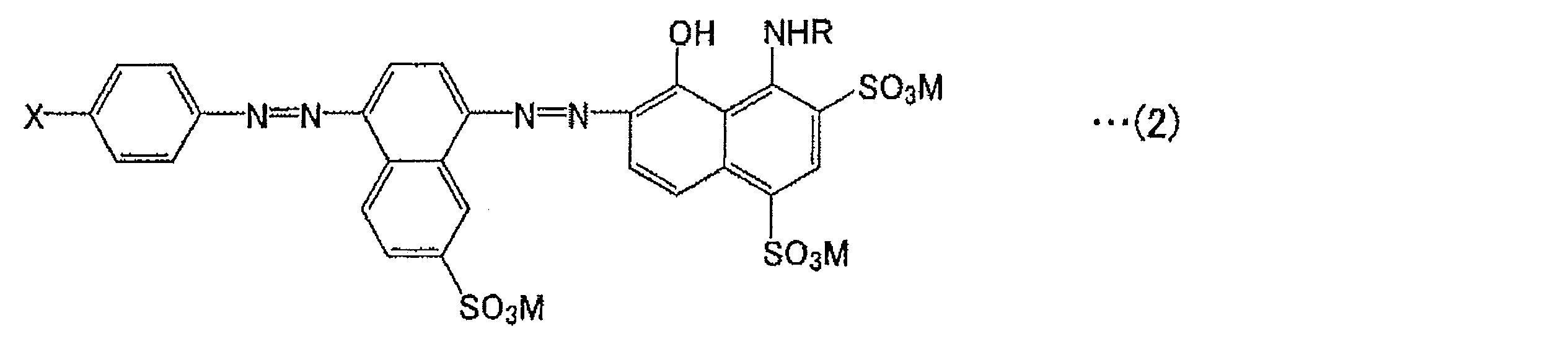
- the azo compound is preferably represented by the following general formula (2).
- R and M are the same as in formula (1).
- X represents a hydrogen atom, a halogen atom, a nitro group, a cyano group, an alkyl group having 1 to 4 carbon atoms, an alkoxy group having 1 to 4 carbon atoms, or an —SO 3 M group.
- the azo compound can be produced, for example, by the method described in JP2009-173849A.
- the solvent is not particularly limited as long as it can dissolve the lyotropic liquid crystal compound, but a hydrophilic solvent is preferable.
- the hydrophilic solvent include water, alcohols, cellosolves, and mixed solvents thereof, and among these, water is preferable.
- a water-soluble compound such as glycerin or ethylene glycol may be added to the solvent.
- the concentration of the lyotropic liquid crystal compound solution is lower than the isotropic phase-liquid crystal phase transition concentration. That is, the lyotropic liquid crystal compound solution is in a state that does not exhibit liquid crystallinity (isotropic phase). If such a lyotropic liquid crystal compound solution is used, it becomes easy to orient in parallel or orthogonal to the extending
- the concentration of the lyotropic liquid crystal compound solution is not particularly limited as long as it is lower than the isotropic phase-liquid crystal phase transition concentration, but it is usually preferably 1 to 10% by weight with respect to the total weight of the solution. .
- the lyotropic liquid crystal compound solution may be applied by any method as long as it can be cast uniformly. For example, a wire bar, a gap coater, a comma coater, a gravure coater, a tension web coater, a slot die coater, or the like can be used.
- the temperature at the time of application is not particularly limited, but it can be performed at room temperature (about 23 ° C.).
- the application direction is not particularly limited, and may be a direction parallel to the stretching direction of the stretched resin film or a direction perpendicular to the stretching direction. is not.
- the liquid crystal compound can be sufficiently aligned even when shearing is not applied.
- thermotropic liquid crystal compound solution used in the present invention usually contains a thermotropic liquid crystal compound and a solvent that dissolves the thermotropic liquid crystal compound.
- solvent and the coating method for the thermotropic liquid crystal compound solution include the same as in the case of the lyotropic liquid crystal compound.
- liquid crystal compound solution used in the present invention as long as the effects of the present invention are not impaired.
- Examples of the polymer compound include those described in JP 2009-263453 A, and examples of the metal scavenger include compounds described in JP 2010-66616 A. Can do.
- step 3 the coated liquid crystal compound solution is solidified to form a polarizing film in which the liquid crystal compound is aligned.
- the “solidification” is to evaporate the solvent to such an extent that the orientation of the liquid crystal compound in the applied liquid crystal compound solution is fixed.
- the liquid crystal compound solution is a lyotropic liquid crystal compound solution
- the solution concentration is changed to change the phase from the isotropic phase to the liquid crystal phase, and the liquid crystal molecules are aligned to form a polarizing film.
- the method for changing the solution concentration is not particularly limited, and examples thereof include a method of naturally evaporating the solvent and a method of evaporating the solvent by heating.
- the polarizing film can be formed by changing the phase from the isotropic phase to the liquid crystal phase by aligning the temperature and aligning the liquid crystal molecules.
- the temperature for phase transition can be appropriately selected depending on the type of liquid crystal compound used.
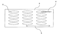
- FIG. 2 shows an embodiment of the present invention, and the present invention is not limited to this.
- the absorption axis 6 (liquid crystal molecule orientation direction) of the polarizing film of the optical laminate obtained by the production method of the present invention is substantially parallel to the slow axis direction 4 (stretching direction of the stretched resin film) of the stretched resin film 2.
- the absorption axis 6 of the polarizing film is the major axis direction of the molecules of the liquid crystal compound.
- substantially parallel means that the angle formed by the slow axis direction 4 of the stretched resin film 2 and the absorption axis 6 of the polarizing film is about 0 ° ⁇ 5 °.
- the concentration of the liquid crystal compound in the formed polarizing film is preferably 80 to 100% by weight with respect to the total weight of the polarizing film. Further, the thickness of the polarizing film is preferably 0.1 to 10 ⁇ m, and more preferably 0.1 to 5 ⁇ m.
- the formed polarizing film exhibits absorption dichroism at any wavelength in the visible light region and has an absorption axis in one direction in the plane.
- Absorption dichroism is obtained by aligning a liquid crystal compound in a polarizing film.
- the absorption axis direction or the transmission axis direction of the polarizing film is substantially parallel to the longitudinal direction of the stretched resin film (long side direction of the film along the longitudinal direction). Note that “substantially parallel” is the same as described above.
- the degree of polarization of the polarizing film formed by the production method of the present invention is preferably 10% or more, more preferably 50% or more, and further preferably 90% or more.
- the method for measuring the degree of polarization can be measured by the method described in the examples.
- the optical laminate 1 of the present invention has a polarizing film 3 directly applied and formed on a stretched resin film 2, and the surface of the stretched resin film 2 has a surface orientation. No treatment is performed, and the slow axis 4 of the stretched resin film 2 and the absorption axis 6 of the polarizing film are substantially parallel.
- direct coating formation means forming a polarizing film directly on a resin film without using an adhesive.
- the aforementioned easy-adhesive layer or the like may be provided between the resin film and the polarizing film.
- the method for producing the optical laminate of the present invention is not particularly limited, but it is preferably produced by the above-described production method of the present invention. Moreover, about the material of a resin film or a polarizing film, film thickness, etc., the above-mentioned material, film thickness, etc. are employable. Further, substantially parallel is the same as described above.
- optical laminated body obtained by this invention can be used for a liquid crystal display, an organic EL display, etc., for example.
- k 1 is the transmission spectrum when the incident polarized light having electric field vector parallel to the transmission axis of the polarizing film
- k 2 if the incident polarized light having a perpendicular electric field vector the transmission axis of the polarizing film Is the transmission spectrum.
- the measurement wavelength was 380 to 780 nm.
- Production Example 1 (Preparation of lyotropic liquid crystal aqueous solution in liquid crystal phase state) Diazotization of 4-nitroaniline and 8-amino-2-naphthalenesulfonic acid by a conventional method (Toyo Hosoda, “Theoretical Manufacturing, Dye Chemistry, 5th Edition”, issued July 15, 1968, Technique Hall, pages 135-152) And a coupling reaction to obtain a monoazo compound.
- the obtained monoazo compound is similarly diazotized by a conventional method, and is further subjected to a coupling reaction with 1-amino-8-naphthol-2,4-disulfonic acid lithium salt to produce a crude product containing an azo compound of the following structural formula (3) And an azo compound of the following structural formula (3) was obtained by salting out with lithium chloride.
- the azo compound having the above structural formula (3) was dissolved in ion-exchanged water to prepare a 20% by weight aqueous solution (Coating Solution 1).
- This aqueous solution was collected with a poly dropper, sandwiched between two glass slides, and observed with a polarizing microscope at room temperature (23 ° C.). As a result, a nematic liquid crystal phase was observed.
- Production Example 2 (Preparation of lyotropic liquid crystal aqueous solution in isotropic phase state)
- the azo compound of the above structural formula (3) was dissolved in ion-exchanged water to prepare an 8% by weight aqueous solution (Coating Solution 2).
- This aqueous solution was collected with a poly dropper, sandwiched between two slide glasses, and observed with a polarizing microscope at room temperature (23 ° C.). As a result, the nematic liquid crystal layer was not observed and was in an isotropic phase.
- the stretched resin film is not subjected to surface orientation treatment such as rubbing treatment or photo-alignment treatment, and is subjected to corona treatment for surface hydrophilization, and then a bar coater (product name: Mayer rot HS3, in the stretching direction of the stretched resin film).
- the coating liquid 2 prepared in Production Example 2 was applied using a product manufactured by BUSHMAN (coating temperature: 23 ° C.), naturally dried in a thermostatic chamber at 23 ° C., and a polarizing film (thickness) on the stretched resin film. : 0.2 ⁇ m) was obtained.
- the polarizing properties of this polarizing plate are a single transmittance of 39.4% and a degree of polarization of 98.9%.
- the absorption axis of the polarizing film (major axis direction of the molecules of the liquid crystal compound) and the slow axis of the stretched resin film (stretched) The angle formed by (direction) was 0.1 °.
- Example 2 A polarizing plate was produced in the same manner as in Example 1 except that the coating direction of the coating liquid 2 was changed to a direction perpendicular to the stretching direction of the stretched resin film.
- the polarizing properties of this polarizing plate were a single transmittance of 39.6% and a degree of polarization of 98.5%, and the angle formed by the absorption axis of the polarizing film and the slow axis of the stretched resin film was 0.1 °.
- the obtained stretched resin film had a thickness of 81 ⁇ m, an in-plane retardation value of 142 nm, and an Nz coefficient of 1.31.
- the polarizing characteristics of this polarizing plate were a single transmittance of 39.7% and a degree of polarization of 98.4%, and the angle formed by the absorption axis of the polarizing film and the slow axis of the stretched resin film was 0.0 °.
- Example 4 A polarizing plate was produced in the same manner as in Example 3 except that the coating direction of the coating liquid 2 was changed to a direction perpendicular to the stretching direction of the stretched resin film.
- the polarizing characteristics of this polarizing plate were a single transmittance of 39.5% and a degree of polarization of 98.7%, and the angle formed by the absorption axis of the polarizing film and the slow axis of the stretched resin film was 0.3 °.
- the obtained stretched resin film had a thickness of 71 ⁇ m, an in-plane retardation value of 187 nm, and an Nz coefficient of 1.27.
- the polarizing properties of this polarizing plate were a single transmittance of 39.7% and a degree of polarization of 98.6%, and the angle formed by the absorption axis of the polarizing film and the slow axis of the stretched resin film was 0.4 °.
- Example 6 A polarizing plate was produced in the same manner as in Example 5 except that the coating direction of the coating liquid 2 was changed to a direction perpendicular to the stretching direction of the stretched resin film.
- the polarizing properties of this polarizing plate were a single transmittance of 39.8% and a degree of polarization of 98.4%, and the angle formed by the absorption axis of the polarizing film and the slow axis of the stretched resin film was 0.2 °.
- the obtained stretched resin film had a thickness of 61 ⁇ m, an in-plane retardation value of 220 nm, and an Nz coefficient of 1.18.
- the polarizing properties of this polarizing plate were a single transmittance of 40.1% and a degree of polarization of 98.7%, and the angle formed by the absorption axis of the polarizing film and the slow axis of the stretched resin film was 0.2 °.
- Example 8 A polarizing plate was produced in the same manner as in Example 7 except that the coating direction of the coating liquid 2 was changed to a direction perpendicular to the stretching direction of the stretched resin film.
- the polarizing properties of this polarizing plate were a single transmittance of 39.9% and a degree of polarization of 98.7%, and the angle between the absorption axis of the polarizing film and the slow axis of the stretched resin film was 0.1 °.
- Comparative Example 1 A polarizing plate was produced in the same manner as in Example 1 except that the resin film was not stretched (unstretched resin film, in-plane birefringence: 0.000).
- This polarizing plate was a single transmittance of 39.8% and a degree of polarization of 0.0%, and it did not function as a polarizing plate.
- Comparative Example 2 A polarizing plate was produced in the same manner as in Example 7, except that the bar coater used was May rot HS1.5 manufactured by BUSHMAN, and the coating liquid used was the coating liquid 1 prepared in Production Example 1. did.
- the polarizing characteristics of this polarizing plate were a single transmittance of 35.3% and a degree of polarization of 2.6%, which did not function as a polarizing plate.
Landscapes
- Physics & Mathematics (AREA)
- Engineering & Computer Science (AREA)
- General Physics & Mathematics (AREA)
- Manufacturing & Machinery (AREA)
- Ophthalmology & Optometry (AREA)
- Mechanical Engineering (AREA)
- Optics & Photonics (AREA)
- Chemical & Material Sciences (AREA)
- Crystallography & Structural Chemistry (AREA)
- Health & Medical Sciences (AREA)
- Nonlinear Science (AREA)
- Mathematical Physics (AREA)
- Polarising Elements (AREA)
- Liquid Crystal (AREA)
- Laminated Bodies (AREA)
Abstract
本発明は、基材となる樹脂フィルムにラビング処理等の表面配向処理をすることなく、簡便に所望の光学特性を有する偏光膜を形成することができる光学積層体の製造方法を提供することを目的とする。本発明は、延伸された樹脂フィルム2及び偏光膜3を含む光学積層体1の製造方法であって、延伸された樹脂フィルム2を準備する工程、前記延伸された樹脂フィルム2上に等方相状態の液晶化合物溶液を塗工する工程、及び、前記塗工した液晶化合物溶液を固化させ、液晶化合物5が配向した偏光膜3を形成する工程、を含み、前記延伸された樹脂フィルム2の遅相軸4と前記偏光膜3の吸収軸6とが略平行であり、かつ、前記延伸された樹脂フィルム2が表面配向処理されていないことを特徴とする光学積層体1の製造方法に関する。
Description
本発明は、延伸された樹脂フィルム上に偏光膜が積層された光学積層体の製造方法及び光学積層体に関する。
位相差フィルム等の基材上に、偏光膜が積層された積層偏光板としては、種々のものが知られており、その製造方法としては、例えば、ラビング処理等の表面配向処理が施された基材や、配向膜を有する基材上に、液晶化合物を含むコーティング液を塗布して液晶配向層を形成する方法等が知られている(例えば、特許文献1、2参照)。
また、配向軸を有する配向基材上に、サーモトロピック液晶ポリマーと二色性色素を含有する溶液を塗布し、前記液晶ポリマーを液晶転移温度以上に加熱して偏光子を形成する、偏光板の製造方法が知られている(例えば、特許文献3参照)。
前述のような液晶化合物を含むコーティング液を塗布して偏光膜を形成する方法は、偏光膜形成にあたり延伸工程を必要とせず、また、偏光膜の膜厚を薄くすることができるため注目されている。しかしながら、前記特許文献1、2に記載された製造方法では、基材に表面配向処理を要するものであるが、このような表面配向処理は大型の処理設備を必要とするため、そのような処理をせずとも所望の光学特性を有する偏光膜を形成する方法が切望されている。
さらに、表面配向処理を行うことで、基材表面にキズが発生したり、異物が付着したりするため、当該キズが生じた部分や異物が付着した部分から微細な表面欠陥が発生しやすく、当該欠陥を有する基材上に形成した偏光膜には、局所的な配向乱れが発生しやすいという問題があった。特に、繊維布で擦る等のラビング処理を行った場合には、基材表面に繊維片等の異物が付着しやすく、前記問題が顕著であった。
また、特許文献3に記載された製造方法においては、液晶化合物を液晶状態で塗工するものであるが、塗工時にかかるせん断力による配向状態への影響が不可避のため、基材延伸方向への配向制御が困難であり、さらに、このようなせん断力が配向不良の原因となる場合がある。なお、せん断力のかかる方向を基材延伸方向に完全に一致するように塗工方向を制御すれば、理想的には液晶化合物を基材延伸方向に配向させることは可能とも考えられるが、特に長尺フィルムに対する塗工工程においては、フィルムは長手方向に連続的に搬送される関係上、フィルムに対する塗工方向を制御することは非常に困難であった。
本発明は、基材となる樹脂フィルムにラビング処理等の表面配向処理をすることなく、簡便に所望の光学特性を有する偏光膜を形成することができる光学積層体の製造方法を提供することを目的とする。
上記問題点に鑑み、鋭意検討の結果、以下の製造方法とすることで、前述の従来の問題点を解消することができることを見出したものである。
本発明は、延伸された樹脂フィルム及び偏光膜を含む光学積層体の製造方法であって、
延伸された樹脂フィルムを準備する工程、
前記延伸された樹脂フィルム上に等方相状態の液晶化合物溶液を塗工する工程、及び、
前記塗工した液晶化合物溶液を固化させ、液晶化合物が配向した偏光膜を形成する工程、を含み、
前記延伸された樹脂フィルムの遅相軸と前記偏光膜の吸収軸とが略平行であり、かつ、
前記延伸された樹脂フィルムが表面配向処理されていないことを特徴とする光学積層体の製造方法に関する。
延伸された樹脂フィルムを準備する工程、
前記延伸された樹脂フィルム上に等方相状態の液晶化合物溶液を塗工する工程、及び、
前記塗工した液晶化合物溶液を固化させ、液晶化合物が配向した偏光膜を形成する工程、を含み、
前記延伸された樹脂フィルムの遅相軸と前記偏光膜の吸収軸とが略平行であり、かつ、
前記延伸された樹脂フィルムが表面配向処理されていないことを特徴とする光学積層体の製造方法に関する。
前記樹脂フィルムの波長590nmにおける面内複屈折が0.0005以上であることが好ましい。
等方相状態の液晶化合物溶液が、等方相-液晶相転移濃度よりも希釈されたリオトロピック液晶化合物溶液であることが好ましい。
前記偏光膜の偏光度が10%以上であることが好ましい。
また、本発明は、延伸された樹脂フィルム上に偏光膜が直接塗布形成された光学積層体であって、
前記延伸された樹脂フィルムの表面には、表面配向処理が施されておらず、
前記延伸された樹脂フィルムの遅相軸と前記偏光膜の吸収軸とが略平行であることを特徴とする光学積層体に関する。
前記延伸された樹脂フィルムの表面には、表面配向処理が施されておらず、
前記延伸された樹脂フィルムの遅相軸と前記偏光膜の吸収軸とが略平行であることを特徴とする光学積層体に関する。
本発明においては、表面配向処理を施していない延伸された樹脂フィルムに、等方相状態の液晶化合物溶液を塗布するため、基材にラビング処理等の表面配向処理をしなくとも、液晶化合物を樹脂フィルムの延伸方向と略平行に配向させることができる。本発明においては、延伸された樹脂フィルムに表面配向処理をしていないので、延伸された樹脂フィルムに表面欠陥が発生しにくく、その結果、当該延伸された樹脂フィルム上に形成した偏光膜の局所的な配向乱れの発生を抑制できるものである。
1.光学積層体の製造方法
本発明は、延伸された樹脂フィルム(以下、延伸樹脂フィルムということがある)及び偏光膜を含む光学積層体の製造方法であって、
(工程1)延伸された樹脂フィルムを準備する工程、
(工程2)前記延伸された樹脂フィルム上に等方相状態の液晶化合物溶液を塗工する工程、
(工程3)前記塗工した液晶化合物溶液を固化させ、液晶化合物が配向した偏光膜を形成する工程、を含み、
前記延伸された樹脂フィルムの遅相軸と前記偏光膜の吸収軸とが略平行であり、かつ、
前記延伸された樹脂フィルムが表面配向処理されていないことを特徴とする光学積層体の製造方法に関する。
本発明は、延伸された樹脂フィルム(以下、延伸樹脂フィルムということがある)及び偏光膜を含む光学積層体の製造方法であって、
(工程1)延伸された樹脂フィルムを準備する工程、
(工程2)前記延伸された樹脂フィルム上に等方相状態の液晶化合物溶液を塗工する工程、
(工程3)前記塗工した液晶化合物溶液を固化させ、液晶化合物が配向した偏光膜を形成する工程、を含み、
前記延伸された樹脂フィルムの遅相軸と前記偏光膜の吸収軸とが略平行であり、かつ、
前記延伸された樹脂フィルムが表面配向処理されていないことを特徴とする光学積層体の製造方法に関する。
(1)工程1
工程1では、延伸された樹脂フィルムを準備する。延伸された樹脂フィルムは、樹脂フィルムを延伸することにより得られる。
工程1では、延伸された樹脂フィルムを準備する。延伸された樹脂フィルムは、樹脂フィルムを延伸することにより得られる。
本発明で用いる樹脂フィルムとしては、特に限定されるものではないが、例えば、シクロオレフィン系樹脂フィルム、セルロース系樹脂フィルム、アクリル系樹脂フィルム、ポリカーボネート系樹脂フィルム、ポリエステル系樹脂フィルム等を挙げることができる。これらの中でも、シクロオレフィン系樹脂フィルムが好ましく、ノルボルネン系樹脂フィルムがより好ましい。
また、前記樹脂フィルムの厚みは、特に制限はないが、例えば、20~200μmであることが好ましい。また、延伸後の樹脂フィルムの厚みは、延伸前の樹脂フィルムの厚み、延伸方法や延伸倍率等によるが、例えば、10~150μmであることが好ましい。
延伸方法としては、一軸延伸法、同時二軸延伸法、逐次二軸延伸法等を挙げることができ、延伸手段としては、ロール延伸機、テンター延伸機、および二軸延伸機等の任意の適切な延伸機を用いることができる。本発明においては、延伸樹脂フィルムが位相差フィルムであることが好ましいため、延伸方法としては、一軸延伸や、縦方向と横方向で延伸倍率が異なる、二軸延伸であることが好ましく、一軸延伸であることがより好ましい。また、樹脂フィルムが、長尺状の樹脂フィルムである場合、代表的には、長手方向(フィルムの長辺方向)に遅相軸が生じるように、長尺状樹脂フィルムを長手方向(又はそれと直交する幅方向)に一軸延伸する方法が挙げられる。
延伸倍率は、用いるフィルムの材料の種類や、所望のNz係数等によって適宜設定することができるが、例えば、未延伸の樹脂フィルムの元長に対して1.01~5倍程度に延伸されることが好ましく、1.1~5倍程度に延伸されることがより好ましい。また、延伸時の温度も特に限定されるものではないが、例えば、80~200℃で延伸することが好ましい。
延伸処理された樹脂フィルム(延伸樹脂フィルム)の波長590nmにおける面内複屈折(Δn=nx-ny)が0.0005以上であることが好ましく、0.0005~0.5であることがより好ましく、0.0005~0.3であることがさらに好ましい。また、延伸時のプロセス制御性および液晶化合物の配向性の観点からは、前記面内複屈折が、0.001~0.1であることが好ましく、0.001~0.05であることがより好ましい。面内複屈折が前記範囲にあることで、当該延伸樹脂フィルム上に塗工した液晶化合物(液晶化合物については後述する)を、延伸樹脂フィルムの延伸方向と略平行に配向することができるため好ましい。ここで、nx及びnyは、それぞれx方向およびy方向の屈折率であり、xは、xy平面での最大屈折率の方向とし、y方向は、それに垂直とする方向である。
また、延伸処理された樹脂フィルムの面内の位相差値{(nx-ny)×厚み}は、適宜設定することができるが、例えば、10~2000nmであることが好ましく、10~1000nmであることがより好ましい。また、厚み方向複屈折(nx-nz)と前記面内複屈折(nx-ny)との関係を示すNz係数(Nz=(nx-nz)/(nx-ny))が、0以上であることが好ましく、0~10であることがより好ましく、0.1~8であることがさらに好ましい。また、延伸時のプロセス制御性および液晶化合物の配向性の観点からは、Nz係数が、1.5以下であることが好ましく、0~1.2であることがより好ましく、0.3~1.2であることがさらに好ましい。ここで、nzは、厚み方向の屈折率である。
前記Nz係数は、樹脂フィルムを延伸する際の縦方向(長手方向)及び横方向(幅方向)の延伸倍率を制御することにより適宜調整することができる。例えば、Nz係数を大きくするためには、縦方向に延伸しつつ、横方向の延伸倍率を大きくすればよく、Nz係数を小さくするためには、縦方向に延伸しつつ、横方向の延伸倍率を小さくするか横方向には収縮させるとよい。
また、本発明において用いる延伸樹脂フィルムは、表面配向処理を施していないものである。このような表面配向処理を施していない前述のような特定の延伸樹脂フィルムを、後述する液晶化合物溶液を塗布する基材として用いることで、ラビング処理等の表面配向処理がなくとも、後述する液晶化合物を樹脂フィルムの延伸方向と略平行に配向させることができる。本発明においては、延伸樹脂フィルムに表面配向処理をしていないので、延伸樹脂フィルムに表面欠陥が発生しにくく、その結果、当該延伸樹脂フィルム上に形成した偏光膜の局所的な配向乱れの発生を抑制できるものである。
本発明の製造方法においては、延伸樹脂フィルムと後述する偏光膜とが接着剤層を介さずに積層することができるものであるが、偏光膜との密着性を向上させるために、前記延伸樹脂フィルムに、コロナ処理、親水化処理などの表面処理を行ってもよく、また、前記延伸樹脂フィルムの偏光膜を積層する側の表面にポリウレタン系樹脂層などからなる厚み数ミクロン程度の易接着層を形成することもできる。
(2)工程2
工程2では、前記延伸樹脂フィルム上に等方相状態の液晶化合物溶液を塗工する。
工程2では、前記延伸樹脂フィルム上に等方相状態の液晶化合物溶液を塗工する。
液晶化合物としては、リオトロピック液晶化合物とサーモトロピック液晶化合物のいずれであってもよいが、リオトロピック液晶化合物の方が好ましい。ここで、「リオトロピック液晶化合物」とは、溶媒に溶解して液晶化合物溶液となり、溶液中の濃度変化により、等方相から液晶相へ(またはその逆の)相変化を起こす液晶化合物である。このとき、液晶性を示さない状態(等方相)から液晶性を示す状態(液晶相)に転移する濃度を等方相-液晶相転移濃度という。また、「サーモトロピック液晶化合物」とは、熱によって等方相から液晶相へ(またはその逆の)相変化を起こす液晶化合物である。このとき、液晶性を示さない状態(等方相)から液晶性を示す状態(液晶相)に転移する温度を等方相-液晶相転移温度という。
従って、本発明において、「等方相状態の液晶化合物溶液」とは、具体的には、等方相-液晶相転移濃度よりも希釈された濃度の液晶化合物溶液、又は、等方相-液晶相転移温度よりも高い温度の液晶化合物溶液等であって、液晶性を示さない状態(等方相)のものである。
本発明に用いられるリオトロピック液晶化合物溶液は、通常、リオトロピック液晶化合物と当該リオトロピック液晶化合物を溶解する溶媒とを含む。前記リオトロピック液晶化合物は、例えば、アゾ系化合物、アントラキノン系化合物、ペリレン系化合物、キノフタロン系化合物、ナフトキノン系化合物、メロシアニン系化合物等が挙げられ、これらの中でもアゾ系化合物が好ましい。
これらの液晶化合物は、それ自体が二色性を示すものであるが、二色性を示さない液晶化合物を併用することもできる。また、色調を調整するなどの目的で、2種以上の液晶化合物を併用してもよい。
アゾ系化合物としては、例えば、下記一般式(1):

(式中、Q1は置換基を有していてもよいアリール基を表わし、Q2は置換基を有していてもよいアリーレン基を表わし、Rは水素原子、炭素数1~3のアルキル基、アセチル基、ベンゾイル基またはフェニル基(これらの基は置換基を有していてもよい)を表わし、Mは対イオンを表わす。)
で表わされるアゾ化合物を挙げることができる。
で表わされるアゾ化合物を挙げることができる。
Mは対イオンを表わし、好ましくは、水素原子、アルカリ金属原子、アルカリ土類金属原子、前記金属の金属イオンまたは置換もしくは無置換のアンモニウムイオンである。金属イオンとしては、例えばLi+、Na+、Ni2+、Fe3+、Cu2+、Ag+、Zn2+、Al3+、Pd2+、Cd2+、Sn2+、Co2+、Mn2+、Ce3+などが挙げられる。対イオンMが多価イオンの場合は複数のアゾ化合物が一つの多価イオン(対イオン)を共有する。
前記アゾ化合物は、好ましくは下記一般式(2)で表わされるものである。式(2)中、RおよびMは式(1)と同様である。Xは水素原子、ハロゲン原子、ニトロ基、シアノ基、炭素数1~4のアルキル基、炭素数1~4のアルコキシ基または-SO3M基を表わす。
前記アゾ化合物は、例えば、特開2009-173849号公報に記載されている方法により製造することができる。
前記溶媒としては、リオトロピック液晶化合物を溶解できるものであればよいが、親水性溶媒が好ましい。親水性溶媒としては、水、アルコール類、セロソルブ類およびそれらの混合溶媒を挙げることができ、これらの中でも水が好ましい。また、溶媒には、グリセリン、エチレングリコール等の水溶性の化合物が添加されていてもよい。
前記リオトロピック液晶化合物溶液の濃度は、等方相-液晶相転移濃度よりも低い。すなわち、リオトロピック液晶化合物溶液は、液晶性を示さない状態(等方相)のものである。このようなリオトロピック液晶化合物溶液を用いれば、塗布する際のせん断応力の影響を受けずに、延伸樹脂フィルムの延伸方向に平行または直交に配向しやすくなる。
前記リオトロピック液晶化合物溶液の濃度は、等方相-液晶相転移濃度よりも低ければよく、特に限定されるものではないが、通常、溶液総重量に対して1~10重量%であることが好ましい。前記リオトロピック液晶化合物溶液の塗布方法は、均一に流延できるものであればよく、例えば、ワイヤーバー、ギャップコーター、コンマコーター、グラビアコーター、テンションウェブコーター、スロットダイコーターなどを使用することができる。また、塗布時の温度については、特に限定されるものではないが、室温(約23℃)で行うことができる。また、塗布方向については、特に限定されるものではなく、延伸樹脂フィルムの延伸方向に対して平行な方向であっても、延伸方向に対して垂直の方向であってもよく、限定されるものではない。
また、塗布の際のせん断を付与してもよいが、本発明では、せん断を付与しない場合でも、十分に液晶化合物を配向させることができるものである。
本発明に用いられるサーモトロピック液晶化合物溶液は、通常、サーモトロピック液晶化合物と当該サーモトロピック液晶化合物を溶解する溶媒とを含む。サーモトロピック液晶化合物溶液の溶媒、塗布方法としては、リオトロピック液晶化合物の場合と同様のものを挙げることができる。
また、本発明において用いる液晶化合物溶液には、前記液晶化合物、溶媒以外にも、本発明の効果を損なわない範囲で、高分子化合物や金属捕捉剤等を添加することができる。
前記高分子化合物としては、例えば、特開2009-263453号公報に記載されたものを挙げることがで、金属捕捉剤としては、例えば、特開2010-66616号公報に記載された化合物を挙げることができる。
(3)工程3
工程3では、前記塗工した液晶化合物溶液を固化させ、液晶化合物が配向した偏光膜を形成する。
工程3では、前記塗工した液晶化合物溶液を固化させ、液晶化合物が配向した偏光膜を形成する。
前記「固化」とは、塗布した液晶化合物溶液中の液晶化合物の配向が固定される程度にまで溶媒を蒸発させることである。液晶化合物溶液がリオトロピック液晶化合物溶液である場合には、具体的には、溶液濃度を変化させて、等方相から液晶相へ相変化させ、液晶分子を配向させて偏光膜を形成する。溶液濃度を変化させる方法としては、特に限定されないが、自然に溶媒を蒸発させる方法や、加熱して溶媒を蒸発させる方法を挙げることができる。
また、液晶化合物溶液がサーモトロピック液晶溶液である場合は、温度変化により、等方相から液晶相へ相変化させ、液晶分子を配向させて偏光膜を形成することができる。相転移させる温度は、用いる液晶化合物の種類によって適宜選択することができる。
(4)液晶化合物の配向方向
液晶化合物の配向方向について、図2を用いて説明するが、図2は、本発明の一実施形態を示すものであり、これに限定されるものではない。
液晶化合物の配向方向について、図2を用いて説明するが、図2は、本発明の一実施形態を示すものであり、これに限定されるものではない。
本発明の製造方法により得られた光学積層体の偏光膜の吸収軸6(液晶分子の配向方向)は、延伸樹脂フィルム2の遅相軸方向4(延伸樹脂フィルムの延伸方向)と略平行となる。また、図2においては、偏光膜の吸収軸6は、液晶化合物の分子の長軸方向である。ここで略平行とは、延伸樹脂フィルム2の遅相軸方向4と偏光膜の吸収軸6とのなす角が、0°±5°程度であることを意味する。
なお、図2では、延伸樹脂フィルム2の遅相軸方向4と偏光膜の吸収軸6とが略平行となるように配向した場合を模式的に記載しているが、液晶化合物5の種類によっては、分子の長軸方向(吸収軸)とフィルムの延伸方向(遅相軸)とが略直交するように配向する場合もあり、この場合は、分子の短軸方向(透過軸方向)とフィルムの延伸方向(遅相軸)とが略平行になるように配向する。ここで略平行とは、短軸方向とフィルムの延伸方向(遅相軸)とのなす角が、0°±5°程度であることを意味する。
形成された偏光膜中の液晶化合物の濃度は、偏光膜の総重量に対して80~100重量%であることが好ましい。また、偏光膜の厚みは、0.1~10μmであることが好ましく、0.1~5μmであることがより好ましい。
形成された偏光膜は、可視光領域のいずれかの波長で吸収二色性を示し、面内の一方向に吸収軸を有する。吸収二色性は、偏光膜中で液晶化合物が配向することにより得られる。前記偏光膜の吸収軸方向又は透過軸方向は、延伸樹脂フィルムの長手方向(長手方向に沿ったフィルムの長辺方向)に対して略平行である。なお、略平行とは、前記同様である。
(5)偏光膜
本発明の製造方法により形成された偏光膜の偏光度は、10%以上であることが好ましく、50%以上であることが好ましく、90%以上であることがさらに好ましい。偏光度の測定方法は、実施例に記載の方法により測定することができる。
本発明の製造方法により形成された偏光膜の偏光度は、10%以上であることが好ましく、50%以上であることが好ましく、90%以上であることがさらに好ましい。偏光度の測定方法は、実施例に記載の方法により測定することができる。
2.光学積層体
本発明の光学積層体1は、図1、2に示すように、延伸樹脂フィルム2上に偏光膜3が直接塗布形成されており、前記延伸樹脂フィルム2の表面には、表面配向処理が施されておらず、前記延伸樹脂フィルム2の遅相軸4と前記偏光膜の吸収軸6とが略平行であることを特徴とする。
本発明の光学積層体1は、図1、2に示すように、延伸樹脂フィルム2上に偏光膜3が直接塗布形成されており、前記延伸樹脂フィルム2の表面には、表面配向処理が施されておらず、前記延伸樹脂フィルム2の遅相軸4と前記偏光膜の吸収軸6とが略平行であることを特徴とする。
ここで、「直接塗布形成」とは、接着剤を用いることなく、樹脂フィルム上に直接偏光膜を形成することを意味する。ただし、前述の易接着剤層等を樹脂フィルムと偏光膜の間に設けてもよい。
本発明の光学積層体の製造方法は、特に限定されるものではないが、前述の本発明の製造方法により製造することが好ましい。また、樹脂フィルムや偏光膜の材料、膜厚等については、前述の材料、膜厚等を採用することができる。また、略平行についても、前述の通りである。
3.用途
本発明により得られた光学積層体は、例えば、液晶ディスプレイや有機ELディスプレイ等に使用することができる。
本発明により得られた光学積層体は、例えば、液晶ディスプレイや有機ELディスプレイ等に使用することができる。
以下に、本発明を、実施例をあげて説明するが、本発明は下記の実施例に制限されるものではない。
<測定方法>
以下の各実施例および比較例においては、下記の測定方法により評価・測定をおこなった。
以下の各実施例および比較例においては、下記の測定方法により評価・測定をおこなった。
(1)厚みの測定
デジタルゲージ((株)尾崎製作所製、製品名「PEACOCK」)を用いて測定した。
デジタルゲージ((株)尾崎製作所製、製品名「PEACOCK」)を用いて測定した。
(2)単体透過率、偏光度の測定
分光光度計(製品名:V-7100、日本分光(株)製)を用いて、偏光透過スペクトルk1及びk2を測定した。ここで、k1は、偏光膜の透過軸と平行な電界ベクトルを有する偏光を入射した場合の透過スペクトルであり、k2は偏光膜の透過軸と垂直な電界ベクトルを有する偏光を入射した場合の透過スペクトルである。測定波長は380~780nmとした。このスペクトルから、視感度補正を行なった透過率Y1(最大透過率方向の直線偏光の透過率)、Y2(最大透過率方向に直交する方向の透過率)を求め、以下の式により、単体透過率、偏光度を求めた。
単体透過率=(Y1+Y2)/2
偏光度=(Y1-Y2)/(Y1+Y2)
分光光度計(製品名:V-7100、日本分光(株)製)を用いて、偏光透過スペクトルk1及びk2を測定した。ここで、k1は、偏光膜の透過軸と平行な電界ベクトルを有する偏光を入射した場合の透過スペクトルであり、k2は偏光膜の透過軸と垂直な電界ベクトルを有する偏光を入射した場合の透過スペクトルである。測定波長は380~780nmとした。このスペクトルから、視感度補正を行なった透過率Y1(最大透過率方向の直線偏光の透過率)、Y2(最大透過率方向に直交する方向の透過率)を求め、以下の式により、単体透過率、偏光度を求めた。
単体透過率=(Y1+Y2)/2
偏光度=(Y1-Y2)/(Y1+Y2)
(3)偏光膜の吸収軸と延伸樹脂フィルムの遅相軸のなす角の測定方法
王子計測機器(株)製「KOBRA-WPR」(商品名)を用いて、23℃で測定した。測定波長は590nmで行った。
王子計測機器(株)製「KOBRA-WPR」(商品名)を用いて、23℃で測定した。測定波長は590nmで行った。
製造例1(液晶相状態のリオトロピック液晶水溶液の調製)
4-ニトロアニリンと8-アミノ-2-ナフタレンスルホン酸とを常法(細田豊著「理論製造 染料化学 第5版」昭和43年7月15日技法堂発行、135~152頁)によりジアゾ化およびカップリング反応させてモノアゾ化合物を得た。得られたモノアゾ化合物を同様に常法によりジアゾ化し、さらに1-アミノ-8-ナフトール-2,4-ジスルホン酸リチウム塩とカップリング反応させて下記構造式(3)のアゾ化合物を含む粗生成物を得、これを塩化リチウムで塩析することにより下記の構造式(3)のアゾ化合物を得た。

4-ニトロアニリンと8-アミノ-2-ナフタレンスルホン酸とを常法(細田豊著「理論製造 染料化学 第5版」昭和43年7月15日技法堂発行、135~152頁)によりジアゾ化およびカップリング反応させてモノアゾ化合物を得た。得られたモノアゾ化合物を同様に常法によりジアゾ化し、さらに1-アミノ-8-ナフトール-2,4-ジスルホン酸リチウム塩とカップリング反応させて下記構造式(3)のアゾ化合物を含む粗生成物を得、これを塩化リチウムで塩析することにより下記の構造式(3)のアゾ化合物を得た。
上記の構造式(3)のアゾ化合物をイオン交換水に溶解させ、20重量%の水溶液を調製した(塗工液1)。この水溶液をポリスポイトで採取し、2枚のスライドガラスの間に挟み込んで、室温(23℃)にて、偏光顕微鏡で観察したところ、ネマチック液晶相が観察された。
製造例2(等方相状態のリオトロピック液晶水溶液の調製)
上記の構造式(3)のアゾ化合物をイオン交換水に溶解させ、8重量%の水溶液を調製した(塗工液2)。この水溶液をポリスポイトで採取し、2枚のスライドガラスの間に挟み込んで、室温(23℃)にて、偏光顕微鏡で観察したところ、ネマチック液晶層は観測されず、等方相であった。
上記の構造式(3)のアゾ化合物をイオン交換水に溶解させ、8重量%の水溶液を調製した(塗工液2)。この水溶液をポリスポイトで採取し、2枚のスライドガラスの間に挟み込んで、室温(23℃)にて、偏光顕微鏡で観察したところ、ネマチック液晶層は観測されず、等方相であった。
実施例1(バッチ処理)
樹脂フィルムとして、ノルボルネン系樹脂フィルム(商品名:ゼオノア(登録商標)、厚み:100μm、日本ゼオン(株)製)を用い、このフィルムに一軸延伸処理(延伸倍率:1.2倍、温度:145℃)を施し、面内複屈折(λ=590nm)が0.00094の延伸樹脂フィルム(厚み:90μm)を作製した。また、得られた延伸樹脂フィルムの面内の位相差値は、84nmであり、Nz係数は、1.35であった。
樹脂フィルムとして、ノルボルネン系樹脂フィルム(商品名:ゼオノア(登録商標)、厚み:100μm、日本ゼオン(株)製)を用い、このフィルムに一軸延伸処理(延伸倍率:1.2倍、温度:145℃)を施し、面内複屈折(λ=590nm)が0.00094の延伸樹脂フィルム(厚み:90μm)を作製した。また、得られた延伸樹脂フィルムの面内の位相差値は、84nmであり、Nz係数は、1.35であった。
この延伸樹脂フィルムにラビング処理や光配向処理等の表面配向処理は施さず、表面親水化のためにコロナ処理を施した後、当該延伸樹脂フィルムの延伸方向にバーコータ(製品名:Mayer rot HS3、BUSHMAN社製)を用いて製造例2で調製した塗工液2を塗工し(塗工温度:23℃)、23℃の恒温室内で自然乾燥させて、延伸樹脂フィルム上に偏光膜(厚み:0.2μm)を積層した偏光板を得た。
この偏光板の偏光特性は、単体透過率39.4%、偏光度98.9%であり、偏光膜の吸収軸(液晶化合物の分子の長軸方向)と延伸樹脂フィルムの遅相軸(延伸方向)のなす角は0.1°であった。
実施例2
塗工液2の塗工方向を、延伸樹脂フィルムの延伸方向に対して垂直の方向にした以外は実施例1と同様の方法で偏光板を作製した。
塗工液2の塗工方向を、延伸樹脂フィルムの延伸方向に対して垂直の方向にした以外は実施例1と同様の方法で偏光板を作製した。
この偏光板の偏光特性は、単体透過率39.6%、偏光度98.5%であり、偏光膜の吸収軸と延伸樹脂フィルムの遅相軸のなす角は0.1°であった。
実施例3
延伸樹脂フィルムの面内複屈折(λ=590nm)が0.00176になるように延伸した以外は実施例1と同様の方法で偏光板を作製した。得られた延伸樹脂フィルムは厚さ81μmで、面内の位相差値は、142nmであり、Nz係数は、1.31であった。
延伸樹脂フィルムの面内複屈折(λ=590nm)が0.00176になるように延伸した以外は実施例1と同様の方法で偏光板を作製した。得られた延伸樹脂フィルムは厚さ81μmで、面内の位相差値は、142nmであり、Nz係数は、1.31であった。
この偏光板の偏光特性は、単体透過率39.7%、偏光度98.4%であり、偏光膜の吸収軸と延伸樹脂フィルムの遅相軸のなす角は0.0°であった。
実施例4
塗工液2の塗工方向を、延伸樹脂フィルムの延伸方向に対して垂直の方向にした以外は実施例3と同様の方法で偏光板を作製した。
塗工液2の塗工方向を、延伸樹脂フィルムの延伸方向に対して垂直の方向にした以外は実施例3と同様の方法で偏光板を作製した。
この偏光板の偏光特性は、単体透過率39.5%、偏光度98.7%であり、偏光膜の吸収軸と延伸樹脂フィルムの遅相軸のなす角は0.3°であった。
実施例5
延伸樹脂フィルムの面内複屈折(λ=590nm)が0.00263になるように延伸した以外は実施例1と同様の方法で偏光板を作製した。得られた延伸樹脂フィルムの厚さは71μmで、面内の位相差値は、187nmであり、Nz係数は、1.27であった。
延伸樹脂フィルムの面内複屈折(λ=590nm)が0.00263になるように延伸した以外は実施例1と同様の方法で偏光板を作製した。得られた延伸樹脂フィルムの厚さは71μmで、面内の位相差値は、187nmであり、Nz係数は、1.27であった。
この偏光板の偏光特性は、単体透過率39.7%、偏光度98.6%であり、偏光膜の吸収軸と延伸樹脂フィルムの遅相軸のなす角は0.4°であった。
実施例6
塗工液2の塗工方向を、延伸樹脂フィルムの延伸方向に対して垂直の方向にした以外は実施例5と同様の方法で偏光板を作製した。
塗工液2の塗工方向を、延伸樹脂フィルムの延伸方向に対して垂直の方向にした以外は実施例5と同様の方法で偏光板を作製した。
この偏光板の偏光特性は、単体透過率39.8%、偏光度98.4%であり、偏光膜の吸収軸と延伸樹脂フィルムの遅相軸のなす角は0.2°であった。
実施例7
延伸樹脂フィルムの面内複屈折(λ=590nm)が0.00361になるように延伸した以外は実施例1と同様の方法で偏光板を作製した。得られた延伸樹脂フィルムの厚さは61μmで、面内の位相差値は、220nmであり、Nz係数は、1.18であった。
延伸樹脂フィルムの面内複屈折(λ=590nm)が0.00361になるように延伸した以外は実施例1と同様の方法で偏光板を作製した。得られた延伸樹脂フィルムの厚さは61μmで、面内の位相差値は、220nmであり、Nz係数は、1.18であった。
この偏光板の偏光特性は、単体透過率40.1%、偏光度98.7%であり、偏光膜の吸収軸と延伸樹脂フィルムの遅相軸のなす角は0.2°であった。
実施例8
塗工液2の塗工方向を、延伸樹脂フィルムの延伸方向に対して垂直の方向にした以外は実施例7と同様の方法で偏光板を作製した。
塗工液2の塗工方向を、延伸樹脂フィルムの延伸方向に対して垂直の方向にした以外は実施例7と同様の方法で偏光板を作製した。
この偏光板の偏光特性は、単体透過率39.9%、偏光度98.7%であり、偏光膜の吸収軸と延伸樹脂フィルムの遅相軸のなす角は0.1°であった。
比較例1
樹脂フィルムの延伸を行わなかった(無延伸樹脂フィルム、面内複屈折:0.000)以外は実施例1と同様の方法で偏光板を作製した。
樹脂フィルムの延伸を行わなかった(無延伸樹脂フィルム、面内複屈折:0.000)以外は実施例1と同様の方法で偏光板を作製した。
この偏光板の偏光特性は、単体透過率39.8%、偏光度0.0%であり、偏光板としての機能を果たしていなかった。
比較例2
用いたバーコータがBUSHMAN社製 Mayer rot HS1.5であり、かつ、用いた塗工液が製造例1で調製した塗工液1であること以外は実施例7と同様の方法で偏光板を作製した。
用いたバーコータがBUSHMAN社製 Mayer rot HS1.5であり、かつ、用いた塗工液が製造例1で調製した塗工液1であること以外は実施例7と同様の方法で偏光板を作製した。
この偏光板の偏光特性は、単体透過率35.3%、偏光度2.6%であり、偏光板としての機能を果たしていなかった。
1 光学積層体
2 延伸された樹脂フィルム(延伸樹脂フィルム)
3 偏光膜
4 延伸樹脂フィルムの遅相軸方向(延伸方向)
5 液晶化合物
6 偏光膜の吸収軸(液晶化合物の分子の長軸方向)
2 延伸された樹脂フィルム(延伸樹脂フィルム)
3 偏光膜
4 延伸樹脂フィルムの遅相軸方向(延伸方向)
5 液晶化合物
6 偏光膜の吸収軸(液晶化合物の分子の長軸方向)
Claims (5)
- 延伸された樹脂フィルム及び偏光膜を含む光学積層体の製造方法であって、
延伸された樹脂フィルムを準備する工程、
前記延伸された樹脂フィルム上に等方相状態の液晶化合物溶液を塗工する工程、及び、
前記塗工した液晶化合物溶液を固化させ、液晶化合物が配向した偏光膜を形成する工程、を含み、
前記延伸された樹脂フィルムの遅相軸と前記偏光膜の吸収軸とが略平行であり、かつ、
前記延伸された樹脂フィルムが表面配向処理されていないことを特徴とする光学積層体の製造方法。 - 前記樹脂フィルムの波長590nmにおける面内複屈折が0.0005以上であることを特徴とする請求項1に記載の光学積層体の製造方法。
- 等方相状態の液晶化合物溶液が、等方相-液晶相転移濃度よりも希釈されたリオトロピック液晶化合物溶液であることを特徴とする請求項1又は2に記載の光学積層体の製造方法。
- 前記偏光膜の偏光度が10%以上であることを特徴とする請求項1~3のいずれかに記載の光学積層体の製造方法。
- 延伸された樹脂フィルム上に偏光膜が直接塗布形成された光学積層体であって、
前記延伸された樹脂フィルムの表面には、表面配向処理が施されておらず、
前記延伸された樹脂フィルムの遅相軸と前記偏光膜の吸収軸とが略平行であることを特徴とする光学積層体。
Priority Applications (1)
| Application Number | Priority Date | Filing Date | Title |
|---|---|---|---|
| US14/649,608 US10421239B2 (en) | 2012-12-17 | 2013-12-12 | Method for producing an optical laminate comprising a stretched resin film and a polarizing film using a diluted lyotropic liquid crystal compound solution |
Applications Claiming Priority (4)
| Application Number | Priority Date | Filing Date | Title |
|---|---|---|---|
| JP2012274846 | 2012-12-17 | ||
| JP2012-274846 | 2012-12-17 | ||
| JP2013255978A JP6385050B2 (ja) | 2012-12-17 | 2013-12-11 | 光学積層体の製造方法及び光学積層体 |
| JP2013-255978 | 2013-12-11 |
Publications (1)
| Publication Number | Publication Date |
|---|---|
| WO2014097966A1 true WO2014097966A1 (ja) | 2014-06-26 |
Family
ID=50978301
Family Applications (1)
| Application Number | Title | Priority Date | Filing Date |
|---|---|---|---|
| PCT/JP2013/083389 Ceased WO2014097966A1 (ja) | 2012-12-17 | 2013-12-12 | 光学積層体の製造方法及び光学積層体 |
Country Status (4)
| Country | Link |
|---|---|
| US (1) | US10421239B2 (ja) |
| JP (1) | JP6385050B2 (ja) |
| TW (1) | TWI538799B (ja) |
| WO (1) | WO2014097966A1 (ja) |
Cited By (1)
| Publication number | Priority date | Publication date | Assignee | Title |
|---|---|---|---|---|
| JPWO2019082745A1 (ja) * | 2017-10-27 | 2020-11-19 | 住友化学株式会社 | 偏光フィルム及びその製造方法 |
Families Citing this family (2)
| Publication number | Priority date | Publication date | Assignee | Title |
|---|---|---|---|---|
| CN107111044B (zh) * | 2015-01-28 | 2019-08-09 | 日本瑞翁株式会社 | 多层膜、光学各向异性层叠体、圆偏振片、有机电致发光显示装置及制造方法 |
| CN112946949A (zh) * | 2021-02-10 | 2021-06-11 | 惠州市华星光电技术有限公司 | 一种偏光板、显示面板及其制备方法 |
Citations (3)
| Publication number | Priority date | Publication date | Assignee | Title |
|---|---|---|---|---|
| JPH11109353A (ja) * | 1997-10-02 | 1999-04-23 | Nitto Denko Corp | 液晶素子、その製造方法、偏光素子、光学素子、照明装置及び液晶表示装置 |
| JP2005266323A (ja) * | 2004-03-18 | 2005-09-29 | Nitto Denko Corp | 光学素子、集光バックライトシステムおよび液晶表示装置 |
| JP2009173849A (ja) * | 2007-12-28 | 2009-08-06 | Nitto Denko Corp | 液晶性コーティング液および偏光膜 |
Family Cites Families (13)
| Publication number | Priority date | Publication date | Assignee | Title |
|---|---|---|---|---|
| US6630289B1 (en) * | 2000-08-22 | 2003-10-07 | The Hong Kong University Of Science And Technology | Photo-patterned light polarizing films |
| JP4668549B2 (ja) * | 2004-04-21 | 2011-04-13 | 大日本印刷株式会社 | 位相差量可変な光学補償素子およびそれを用いた液晶ディスプレイ |
| EP1998196B9 (en) | 2006-02-28 | 2014-12-31 | Teijin Limited | Layered polarization film, phase difference film, and liquid crystal display device |
| US7966898B2 (en) * | 2006-07-28 | 2011-06-28 | California Institute Of Technology | Polymer NEMS for cell physiology and microfabricated cell positioning system for micro-biocalorimeter |
| JP2008122851A (ja) * | 2006-11-15 | 2008-05-29 | Nitto Denko Corp | 光学積層体、光学積層体の製造方法、及び光学積層体の用途 |
| JP5202889B2 (ja) | 2007-06-29 | 2013-06-05 | 日東電工株式会社 | 積層偏光板およびその製造方法ならびに液晶表示装置 |
| US20100188605A1 (en) * | 2007-07-24 | 2010-07-29 | Masahiro Hasegawa | Liquid crystal display device and polarization plate |
| JP2009092847A (ja) * | 2007-10-05 | 2009-04-30 | Nitto Denko Corp | 液晶パネル及び液晶表示装置 |
| TW200916833A (en) * | 2007-10-15 | 2009-04-16 | Chunghwa Picture Tubes Ltd | Multi-function optical film and polarizer |
| US20090269591A1 (en) * | 2008-04-24 | 2009-10-29 | Crysoptix Kk | Organic Compound, Optical Film and Method of Production thereof |
| JP2010020207A (ja) | 2008-07-14 | 2010-01-28 | Nitto Denko Corp | 光学積層体の製造方法 |
| JP5711588B2 (ja) * | 2011-03-31 | 2015-05-07 | 富士フイルム株式会社 | 3d画像表示装置、3d画像表示装置用パターン偏光板、及び3d画像表示システム |
| TWI546597B (zh) * | 2011-06-09 | 2016-08-21 | 林技術研究所股份有限公司 | 光學膜疊層體及其製造方法與使用此光學膜疊層體之液晶顯示面板 |
-
2013
- 2013-12-11 JP JP2013255978A patent/JP6385050B2/ja active Active
- 2013-12-12 US US14/649,608 patent/US10421239B2/en active Active
- 2013-12-12 WO PCT/JP2013/083389 patent/WO2014097966A1/ja not_active Ceased
- 2013-12-16 TW TW102146376A patent/TWI538799B/zh active
Patent Citations (3)
| Publication number | Priority date | Publication date | Assignee | Title |
|---|---|---|---|---|
| JPH11109353A (ja) * | 1997-10-02 | 1999-04-23 | Nitto Denko Corp | 液晶素子、その製造方法、偏光素子、光学素子、照明装置及び液晶表示装置 |
| JP2005266323A (ja) * | 2004-03-18 | 2005-09-29 | Nitto Denko Corp | 光学素子、集光バックライトシステムおよび液晶表示装置 |
| JP2009173849A (ja) * | 2007-12-28 | 2009-08-06 | Nitto Denko Corp | 液晶性コーティング液および偏光膜 |
Cited By (1)
| Publication number | Priority date | Publication date | Assignee | Title |
|---|---|---|---|---|
| JPWO2019082745A1 (ja) * | 2017-10-27 | 2020-11-19 | 住友化学株式会社 | 偏光フィルム及びその製造方法 |
Also Published As
| Publication number | Publication date |
|---|---|
| US20150343725A1 (en) | 2015-12-03 |
| JP2014139661A (ja) | 2014-07-31 |
| US10421239B2 (en) | 2019-09-24 |
| JP6385050B2 (ja) | 2018-09-05 |
| TWI538799B (zh) | 2016-06-21 |
| TW201427816A (zh) | 2014-07-16 |
Similar Documents
| Publication | Publication Date | Title |
|---|---|---|
| JP6081098B2 (ja) | 長尺状積層偏光板の製造方法及び長尺状積層偏光板 | |
| KR100762158B1 (ko) | 타원 편광판의 제조 방법, 및 타원 편광판을 이용하는 화상표시 장치 | |
| CN110023347B (zh) | 聚合性液晶组合物、光学各向异性膜、光学膜、偏振片、图像显示装置及有机电致发光显示装置 | |
| JP2002006138A (ja) | 光学補償シートおよびその製造方法 | |
| WO2011007592A1 (ja) | 複合フィルムの製造方法および複合フィルム | |
| CN114144707B (zh) | 薄型圆偏振片的制造方法 | |
| JP2004226591A (ja) | 液晶表示装置および偏光板 | |
| JP6385050B2 (ja) | 光学積層体の製造方法及び光学積層体 | |
| CN110023800B (zh) | 聚合性液晶组合物、光学各向异性膜、光学膜、偏振片、图像显示装置及有机电致发光显示装置 | |
| JP2009139825A (ja) | 光学異方膜の製造方法 | |
| JP2006201746A (ja) | 楕円偏光板およびそれを用いた画像表示装置 | |
| JP2004233872A (ja) | 偏光フィルム、楕円偏光フィルム、円偏光フィルム、及び液晶表示装置 | |
| JP5422875B2 (ja) | 異方性光学膜の製造方法 | |
| JP2008077043A (ja) | 光学補償シート、偏光板及び液晶表示装置 | |
| KR102170099B1 (ko) | 이방성 색소막용 조성물, 이방성 색소막 및 광학 소자 | |
| JP3916950B2 (ja) | 光学積層体、及びその製造方法、並びに円偏光板 | |
| CN116148965A (zh) | 带相位差层的偏振片及使用了其的图像显示装置 | |
| TWI551893B (zh) | 3d顯示裝置及3d顯示系統 | |
| JP2009258412A (ja) | コーティング液およびその製造方法、ならびに偏光膜 | |
| JP2004077813A (ja) | 位相差板および円偏光板 | |
| WO2011045959A1 (ja) | コーティング液およびその製造方法、ならびに偏光膜 | |
| JP2025072728A (ja) | 積層フィルムおよび位相差層付偏光板の製造方法 | |
| KR20250017145A (ko) | 광학 적층체 및 상기 광학 적층체를 이용한 화상 표시 장치 | |
| KR20250020308A (ko) | 광학 적층체 | |
| JP2006195424A (ja) | 楕円偏光板およびその製造方法、ならびに楕円偏光板を用いた画像表示装置 |
Legal Events
| Date | Code | Title | Description |
|---|---|---|---|
| 121 | Ep: the epo has been informed by wipo that ep was designated in this application |
Ref document number: 13865173 Country of ref document: EP Kind code of ref document: A1 |
|
| WWE | Wipo information: entry into national phase |
Ref document number: 14649608 Country of ref document: US |
|
| NENP | Non-entry into the national phase |
Ref country code: DE |
|
| 122 | Ep: pct application non-entry in european phase |
Ref document number: 13865173 Country of ref document: EP Kind code of ref document: A1 |